

Page 1

ASSEMBL Y / OPERA TOR'S MANUAL
GA 300 GT GYRORAKE
No 95312 A.GB - 01.97
Page 2
DEAR OWNER,
In buying a KUHN machine you have chosen wisely. Into it have gone years of thought,
research and improvements. You will find, as have thousands of owners all over the world, that
you have the best that engineering skill and actual field testing can produce. You have
purchased a dependable machine, but only by proper care and operation can you expect to
receive the performance and long service built into it.
This manual contains all the necessary information for you to receive full efficiency from your
machine. The performance you get from this machine is largely dependant upon how well you
read and understand this manual and apply this knowledge. Please DO NOT ASSUME THAT
YOU KNOW HOW TO OPERATE AND MAINTAIN YOUR MACHINE before reading this
manual carefully. KEEP THIS MANUAL AVAILABLE FOR REFERENCE.
Your KUHN dealer will instruct you on the general operation of your machine. He is interested
that you get the best performance possible and will be glad to answer any special questions
that may arise regarding the operation of the KUHN machine.
Your KUHN dealer can offer a complete line of genuine KUHN service parts.
These parts are manufactured and carefully inspected in the same factory that builds the
machine to assure high quality and accurate fitting of any necessary replacements.
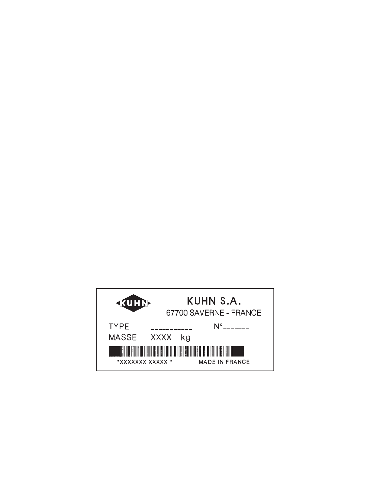
When ordering service parts it is important that you indicate the type of machine concerned
and its serial number.
For this reason please complete the model identification plate diagram below with the required
information. This will provide you with an easy reference for future service parts orders.
ABOUT IMPROVEMENTS
KUHN is continually striving to improve its products and, therefore, reserves the right to make
improvements or changes when it becomes practical to do so, without incurring any
obligations to make changes or additions to the equipment sold previously.
Page 3

- 1 -
CONTENTS
PAGE
Safety 2
Safety decals 7
Technical specifications 9
Assembly 9
Attachment 12
- Fitting to tractor 12
- PTO transmission shaft 13
Working position and adjustments 14
Operation 15
Forward speed 15
Swath screen 16
Transport 16
Parking 17
Lubrication 17
Important recommendations 18
Optional equipment 18
Conditions of limited warranty 19
Copyright 1997 KUHN S.A.
Page 4

- 2 -
SAFETY
The above symbol is used throughout this manual every time recommendations are made concerning your safety,
the safety of others, or the good operation of the machine.
These recommendations must be made known to all machine operators.
DESIGNATED USE OF THE MACHINE
The GA 300 GT Gyrorake must only be used for the work for which it has been designed : raking on the ground and
forming windrows of pre-mowed fodder and straw.
The manufacturer is not held liable for any damage resulting from machine applications other than those specified
by the manufacturer.
Any use other than the designated operation is at the risk and responsibility of the operator.
Designated use of the machine also means :
- following operation, maintenance and repair recommendations given by the manufacturer ;
- using only genuine spare parts, equipment and accessories as designated by the manufacturer.
The GA 300 GT Gyrorake must only be operated, maintained and repaired by competent persons who are familiar
with machine specifications and operation and are aware of any danger involved.
The operator must imperatively respect current legislation concerning :
- accident prevention,
- work safety,
- public traffic circulation.
All safety advice indicated on the machine must be strictly observed.
The manufacturer is not held liable for any damage resulting from machine modifications carried out by the operator
himself or by a third party without previous written agreement from the manufacturer.
Page 5

- 3 -
GENERAL SAFETY RECOMMENDATIONS
Before operating the machine, always ensure that tractor and machine are in accordance with work safety and road
traffic regulations.
BASIC PRINCIPLES
1. In addition to the recommendations given in this manual, legislation on work safety and accident prevention must
also be respected.
2. Advice is indicated on the machine, specifying safety recommendations in order to prevent accidents.
3. Before travelling on public roads, the operator must ensure that the machine conforms to road traffic regulations.
4. Before starting work, the operator must be familiar with all machine controls, handling devices and their
functions. Once at work, it is too late to do so !
5. Do not wear loose clothing which could become caught up in moving elements.
6. Use a tractor equipped with a safety cab. Keep windows and roof hatch closed for reduced sound level while
operating the PTO drive implement.
7. Before starting up the machine and beginning work, check the surrounding area (beware of children !). Make
sure there is sufficient visibility.
Keep all people and animals away from the danger zone of the machine (risk of projection !)
8. Carrying people or animals on the machine when working or in transport is strictly forbidden.
9. Machine must only be attached to tractor using means provided and in accordance with current safety
standards.
10. When attaching or removing the machine, place the parking stand into the corresponding position.
11. Special care should be taken when attaching or removing the machine from the tractor.
12. Before attaching the machine, ensure that the front tractor axle is sufficiently ballasted.
Ballast is to be placed on the supports provided in accordance with instructions of the tractor manufacturer.
13. Do not surpass the maximum axle load or the overall transport weight as prescribed by the tractor manufacturer.
14. Do not exceed the maximum transport width authorized by road traffic regulations.
15. Before transporting the machine on public roads, ensure that all legally required guards and indicators (lights,
reflectors ...) are in place and in good operation.
16. All operating controls (cords, cables, rods...) must be positioned so that they cannot be set off accidently, risking
accident or damage.
Page 6

- 4 -
17. Before traveling on public roads, put the machine into its transport position as instructed in this operator’s
manual.
18. Never leave the tractor seat while the machine is operating.
19. Drive speed must be adapted to ground conditions as well as to roads and paths.
Always avoid abrupt changes of direction.
20. Precision steering, tractor adherence, road holding and efficient braking are influenced by the type of implement,
weight, ballast of front axle, ground or road conditions. It is therefore of utmost importance to be cautious in every
given situation.
21. Be particularly cautious when turning corners, paying attention to machine overhang, length, height and weight.
22. Before operating the machine, ensure that all safety guards are firmly in place and in good condition. If worn
or damaged, replace immediately.
23. Before operating the machine, check the tightness of all nuts and bolts, particularly on fixing elements (blades,
tines, knives, spades ...)
24. Keep clear of the machine operating area.
25. WARNING ! Danger of crushing and shearing can exist when components are operated by hydraulic or
pneumatic controls.
26. Before leaving the tractor or before adjusting, maintaining or repairing the machine, turn off the engine, remove
the ignition key and wait until all moving parts have come to a complete stop.
27. Do not stand between the tractor and the machine unless the hand brake is tight and/or stops have been placed
under the wheels.
28. Before any adjustments, maintenance or repairs are carried out, ensure that the machine cannot be started up
accidentally.
ATTACHMENT
1. When attaching or removing the machine from the tractor, ensure that the machine cannot move unexpectedly
(secure with wedges if necessary).
2. Do not exceed the maximum allowable down pressure applied by the machine drawbar on the tractor hitch point.
3. Ensure that vertical and horizontal pivot angles between machine tongue and tractor hitch point are sufficient to
allow safe operation.
Page 7

- 5 -
POWER TAKE-OFF
1. Use only the PTO shaft supplied with the machine or recommended by the manufacturer.
2. PTO guards must always be in place and in good condition.
3. Check for correct PTO overlap when at work and in transport.
4. Before attaching or removing the PTO shaft, disengage PTO shaft, turn off engine and remove ignition key.
5. If a primary PTO shaft is equipped with a slip clutch or a free wheel, these must be fitted on the machine PTO.
6. Ensure that PTO shaft is always correctly fitted and locked into place.
7. Make sure guards are correctly in place and secured with the safety chains provided.
8. Before engaging PTO, ensure that PTO speed and direction are in accordance with manufacturer's
recommendations.
9. Before engaging PTO, keep all people and animals clear from the machine.
10. Never engage PTO shaft when tractor engine is turned off.
11. Never surpass the PTO angle recommended by the manufacturer.
12. WARNING ! Rotating elements can continue turning momentarily after PTO is disengaged. Keep clear until all
rotating elements are at a standstill.
13. When removing the machine, place PTO shaft on the supports provided.
14. Fit the safety cap on tractor PTO.
15. Replace any worn or damaged PTO guards immediately.
Page 8

- 6 -
TIRES
1. Before any work is performed on the wheels, ensure that the machine rests on the ground and is perfectly stable
so that it cannot move accidentally (put wedges in place).
2. Assembly, disassembly and repair of wheels and tires must only be carried out by competent persons who are
equipped with standardized tools.
3. Check tire pressure regularly !
Respect manufacturer’s recommendations on tire pressure.
MAINTENANCE
1. Before checking for any machine malfunction and before adjusting, maintaining or repairing the machine,
disengage PTO, turn off engine and remove ignition key.
2. Check tightness of nuts and bolts regularly. Retighten if necessary.
3. If the machine is raised, prop it up in a stable position before carrying out any maintenance work.
4. When replacing a working part, wear protection gloves and only use standardized tools.
5. It is forbidden to discard any oil, grease or filters. These must be given to waste disposal organisations to protect
the environment.
6. Disconnect power source before any work is done to the electric system.
7. Check safety guards regularly, particularly those that are subject to wear. Replace immediately if damaged.
8. Spare parts used must be in accordance with specifications and standards as defined by the manufacturer. Use
only genuine KUHN parts !
9. Before any electric welding is carried out on tractor or attached machine, disconnect generator and battery
terminals.
10. Repairs on elements under pressure or tension (springs, accumulators etc...) must only be carried out by
competent persons with standardized equipment.
Page 9
- 7 -
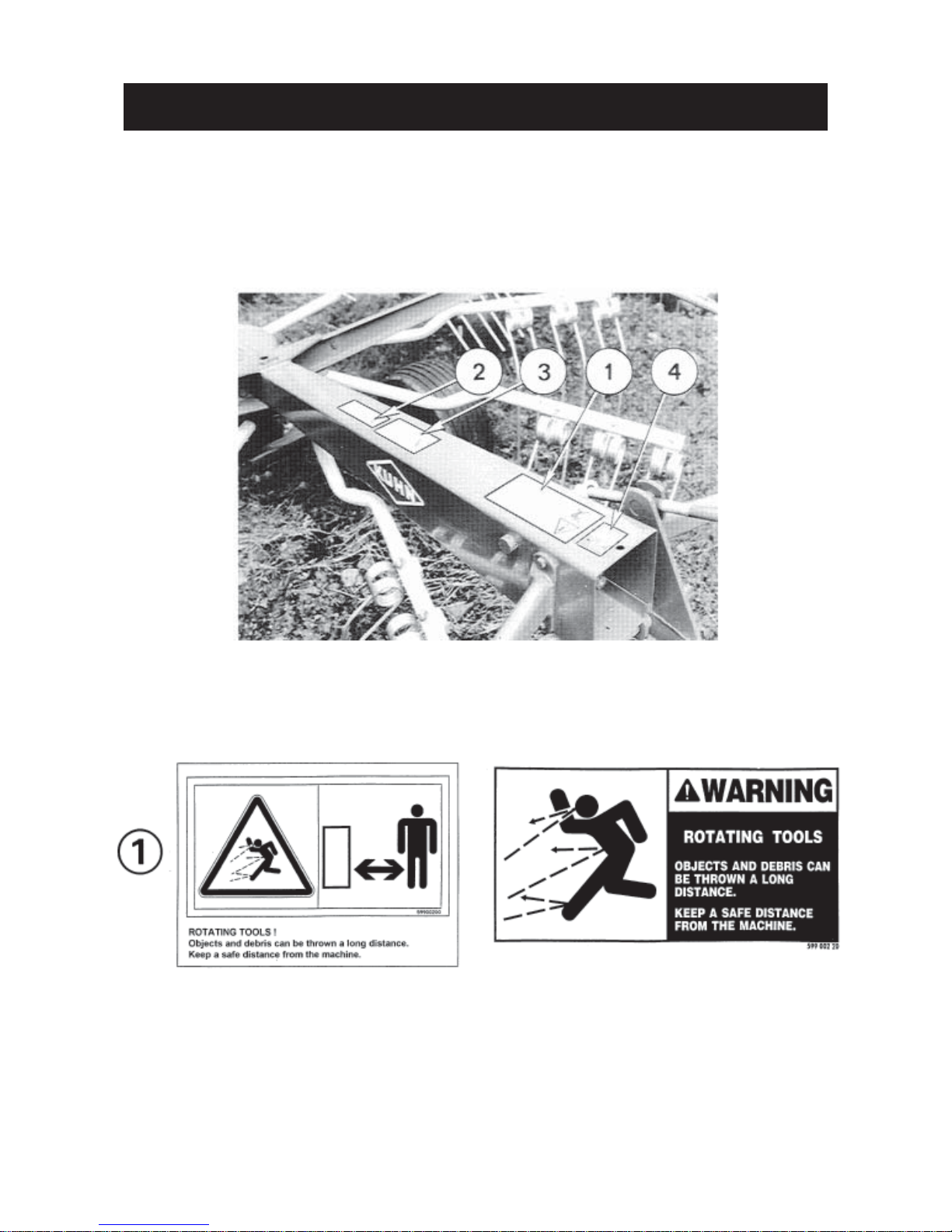
SAFETY DECALS
THE FOLLOWING SAFETY PICTORIALS HAVE BEEN PLACED ON YOUR MACHINE IN THE AREAS
INDICATED. THEY ARE INTENDED FOR YOUR PERSONAL SAFETY AND FOR THE SAFETY OF THE
PEOPLE WORKING WITH YOU. THE TEXT SHOWN ON THEM GIVES THEIR PRECISE MEANING.
ENSURE THAT THESE PICTORIALS ARE ALWAYS LEGIBLE. IF THEY ARE NOT, REPLACE THEM.
Page 10

- 8 -
Page 11

- 9 -
Mounting the wheels
Slide the hub protector plug (01), then the grey protector
plug (02) onto the wheel column (N) (see figure
opposite). Fill wheel caps (Q) with grease. Also
grease the space between both bearings located
inside the rims. Mount the 2 wheels (L) to wheel
column (N). Insert bushes (O) and screw on low
hexagon nut (P) (M 16). Tighten to 10 daNm/75
ft.lbs. Fit wheel caps (Q) in place (see figure opposite).
TECHNICAL SPECIFICATIONS
Tractor attachment Multi-holed bar / drawbar
Working width 3.2 m (10' 6")
Transport width 2.75 m (9')
Work rate per hour 2.5 ha (6.2 acres)
Power required 20 hp
Weight (with PTO) 300 kg (661 lbs)
Tyres 18 x 8,50/8 pressure 2 bar (29 psi)
Forward speed Up to 14 km/hour (8 1/2 mph)
PTO shaft With torque limiter
Number of tine arms 9
Number of tines 27
ASSEMBLY
To facilitate transport, the GA 300 GT is delivered with tines, tine arms, guards, wheels, wheel column hinge and
drawbar unassembled. To assemble these parts, proceed as follows :
Fitting the wheel axle (photo 1)
Raise the wheel axle (T) on a support and after
removing the 4 protective screw plugs attach it to
the rotor flange (S) using the 4 self-locking nuts (U)
(tighten to 21 daNm -155 ft.lbs).
The height adjustment lever (L) (photo 8) must be
positioned towards the rear.
Page 12

- 10 -
Fitting the drawbar (photo 2)
Attach the pre-assembled drawbar (V) - handle (N)
to the chassis (O) using link pins (X) and (Y) and the 4
roll pins (Z) (8 x 40 mm).
Do not forget to insert spacer (W) as shown in photo
2.
Fitting the tine arms (fig.3 & photo 3A)
Fit the tine arms (S) onto the oscillating shafts (L) (fig.3)
making sure that the bent form of the arms faces
forwards when looking in the direction of rotor
rotation (See photo 3A). Secure in place using roll pins
(G) (diameter 12 x 45 and 7 x 45) (fig.3).
IMPORTANT : MAKE SURE THAT ROLL PINS ARE
FITTED 180° TO EACH OTHER AND
THAT THE SLOTS ARE FACING THE
DIRECTION OF ROTATION (fig. 3).
BE SURE THAT THE MATING SURFACES OF TINE ARMS (S) AND
THEIR SHAFTS (L) ARE CLEAN AND
LIGHTLY COATED WITH A NEVER
SEIZE COMPOUND.
NOTE : In figure 3 and photo 3A, the arrow indicates
the direction of rotation of the rotor (looking
from above).
Page 13

- 11 -
Fitting the tines (fig. 4)
The tines (A) must be attached underneath the tine
arms (E) so that their fingers are slanting away from
the direction of rotation (see arrow).
The tines are secured to the arms by using the screw
(B) (M12 x 75), the self-locking nut (G) (M12), the
washer (C) (13 x 35 x 7), the spring washer (F) and the
tine bracket (D). Make sure that all parts are positioned
correctly as shown in figure 4.
FITTING TINE ARMS AND TINES INCORRECTLY RESULTS IN SERIOUS MACHINE
DAMAGE.
Fitting the guards (photo 5)
Attach the guard supports (K) to each side of chassis (O) by means of bracket (F) using the 2 bolts (M)
(M 14 x 30) and one bolt (D) (M 12 x 30) as shown in photo 5. Attach the half guards (L) to each side of the chassis
(O) using bolts (P) (M 10 x 30) with reinforcing plates (Q) located inside the chassis (O). Next attach the other end
to support (K) using bolts (R) (M10 x 30) (photo 5). Do not forget to use the locking washers and nuts.
DO NOT FORGET TO POSITION LOCK WASHERS (M 14 and M 10) AND NUTS (M 14 and M 10) CORRECTLY.
Next fit red reflectors (C) and white reflectors (G) using countersunk head screws (M 5 x 25) and self-locking nuts
(M 5).
Page 14

- 12 -
Fitting the swath screen
(photo 6)
Mount the support (S) of the swath screen inside the
“U” section (E) in one of the 4 fixing holes and secure
with pin (C).
Mount the swath screen (H) to the support (S) in one
of the 3 positions and secure with 2 bolts (J) (screw M8
x 55 and self-locking nut). Do not forget to put the bar
(Z) between the swath screen and bolts (J).
ATTACHMENT
I) Fitting to tractor (photo 7)
The ideal hitch point for the GA 300 GT is on a multi-holed drawbar attached to the tractor lower link arms which
should be set at a height of 40 cm (16") from the ground and locked in place.
If the PTO shaft is fitted with a C.V. joint, machine should be attached to the tractor drawbar for optimal turning ability.
Page 15

- 13 -
II) PTO Transmission Shaft
Fit the PTO shaft to the GA drive shaft and the tractor
PTO drive shaft (safety clutch nearest the machine).
Connect the two safety chains, one to fixation point of
the tractor yoke and the other to the central frame, in
order to prevent rotation of the PTO shaft guards.In the
shortest position, a minimum distance of 3 cm = a (1
1/4") should remain between the ends of the tubes and
yokes (fig. A). If necessary, shorten all four tubes by an
equal amount (fig. B).
Chamfer, clean and grease.
When fitted and with machine correctly positioned, the
PTO shaft tubes must have a minimum overlap of 300
mm = b (12") at their most fully extended position (fig.
A).
To avoid accidents which could be serious, always check that the safety guards are firmly
in place and prevent their rotation by using the safety chains delivered with the machine. One
safety chain must be fixed to a fixed point of the tractor (3-point attachment yoke) and the
other by the hole located in the top plate of the chassis.
Replace worn or damaged guards immediately using only genuine KUHN parts.
Page 16

- 14 -
WORKING POSITION AND ADJUSTMENTS
When working, the tractor linkage must always be stabilized from both sideways and vertical movement.
The height of the GA 300 GT is correct when the tines brush the ground at the front and all tine arms are approximately
horizontal.
To adjust height, proceed as follows :
- Take the machine out of its transport position by unlocking the wheel axle adjustment plate (S) using lever (L)
(photo 8).
- Lower the machine so that the tines just brush the ground.
- Lock the wheel axle adjustment plate (S) into position using lever (L) into the nearest slot.
- To finish the rotor adjustment, use crank handle (M) (photo 8).
Page 17

- 15 -
OPERATION
The GA must never be operated at PTO speeds above 540 rpm. In general, reduce tractor engine speed until the
PTO drive shaft rotates at less then 540 rpm to give gentle crop handling.
If the raking is poor, it may be for either of the following reasons :
1. Poor raking with hay left in the centre (fig. 9) :
Turn the crank handle (M) (photo 8) until the tines lightly brush the ground in the front.
2. Poor raking at the sides (fig. 10) :
Turn the crank handle (M) (photo 8) and adjust the tine height using the wheel axle height adjustment (see
page 8).
According to the density of the crop, the Gyrorake can make single or double swaths. In the second case, the swath
screen should not be used (see fig. 11 and 12).
FORWARD SPEED
The forward speed (up to 14 km/hr - 9 mph) must be determined by the various factors involved : quantity of hay,
contours of the land, etc. It is not possible to recommend a correct speed, theis must be determined by the choice
of work required under the prevailing conditions.
Page 18

- 16 -
SWATH SCREEN
Lateral adjustment :
There are 4 positions (C). According to crop density,
extend or retract the swath screen.
Vertical adjustment :
There are five positions (H). Generally, the swath
screen is secured in the middle position. The other four
positions should be used as needed.
For example :
- Upper positions : in very dense crop or in undulating
ground conditions.
- Lower positions : in light crop to prevent the crop from
passing under the swath creen.
Front and rear adjustment :
Depending on the crop density, the swath screen can
be repositioned forward or back to catch grass projected
sideways.
TRANSPORT
To put the Gyrorake into transport position, proceed as
follows :
- Lock the wheel axle adjustment plate (S) in the upper
position using lever (L) (photo 8).
- Using crank handle (M) (photo 8), put the rotor in the
horizontal position.
- Free the swath screen (G) (photo 14).
- Push the swath screen as far as possible towards
the rotor in order to reduce the width of the GA 300
GT to a minimum.
- Lock the swath screen (G) in this position with the pin
(B) (photo 14).
Page 19

- 17 -
PARKING
The stand (X) fixed to drawbar (Z) allows the GA 300 GT
to be parked without its tines resting on the ground.
PTO shaft (Y) should be rested on its support (V) to
avoid damage and deterioration to the yoke due to
contact with the ground (photo 15).
LUBRICATION
Lubricate the following parts with SHELL Multi-purpose grease NLGI grade 2 :
- Once per day : PTO yoke bearings, telescopic drive tubes and crank handle screw thread (M) (photo 8).
- Every fifty hours : rotor gearbox and the tine arms.
- When replacing a caster wheel, pack wheel cap and the space between both wheel hub bearings with grease.
The central cam controlling the tine arm movement is greased for life.
When necessary, lubricate the pivot points of the machine (drawbar, parking stand, wheel axle, etc.) whith SHELL
X 100 oil.
TO ENSURE TROUBLE FREE OPERATION OF YOUR MACHINE,
WE RECOMMEND SHELL LUBRICANTS.
Page 20

- 18 -
IMPORTANT RECOMMENDATIONS
- Before adjusting or servicing the machine, make sure that the tractor engine is switched off.
- After the first few hours of operation, check all nuts and bolts for tightness, especially the tine bolts.
- Check tire pressure regularly (approximately 2 bar - 29 psi).
- Check regularly that the machine is well lubricated.
- Secure the PTO shaft safety cover with the chains provided.
- Never let the slip clutch slip more than a few seconds.
- Always use the parking stand when the machine is not in use. Do not forget to raise it before operation and
transport.
- Stabilize the tractor linkage from all side to side movement.
OPTIONAL EQUIPMENT
BOGIE AXLE KIT
(Kit no. 113 6370)
This equipment can be recommended to minimize jerks and jolts when operating on very irregular grounds.
To install the bogie axle kit see assembly and operating instructions no. 077 029 00 delivered with the kit.
Page 21

- 19 -
SOUND LEVELS
Sound levels given out by : GA 300 GT Gyrorake
Sound levels have been measured in accordance with the measuring methods as defined in :
HM Agricultural Inspectorate
AGRICULTURAL MACHINERY NOISE
Legislation and guidance on methods of testing
(Annex to AIC 1896/117 REV)
February 1988
Health and Safety Executive
The method employed corresponds to the method No. 4 in this document. Unspecified testing
conditions comply with ISO 5131 standard.
Measuring equipment conforms to NF S 31-009 standard. The tractor used has a power of 66 kW.
A-weighted emission sound pressure level L (A) eq inside tractor cab (with closed windows) :
Tractor only : 72.8 dB (A)
Tractor + machine : 73.9 db (A)
Page 22

LIMITED WARRANTY
KUHN S.A. of 4 Impasse des Fabriques, 67706 SAVERNE CEDEX, France (hereinafter called the
«Company») warrants, in accordance with the provisions below, to each original retail purchaser of
KUHN new equipment of its own manufacture, from an authorized KUHN dealer, that such equipment
is, at the time of delivery to such purchaser, free from defects in material and workmanship and that
such equipment will be warranted for a period of one year starting from the date the goods are delivered
to the end user and during this period up to a limit of 500 hours use, providing the machine is used and
serviced in accordance with the recommendations in the Operator’s Manual.
THESE CONDITIONS ARE SUBJECT TO THE FOLLOWING EXCEPTIONS :
1. Parts of machines which are not of our manufacture i.e. tyres, belts, P.T.O. shafts, clutches etc., are not
covered by this Limited Warranty but are subject to the warranty of the original manufacturer. Any claim
falling into this category will be taken up with the manufacturer concerned.
2. Warranty claims applying to these types of parts must be handled in the same way as if they were parts
manufactured by KUHN. However, compensation will be paid in accordance with the warranty agreement of the manufacturer concerned in as much as the latter justifies such a claim.
3. This Limited Warranty will be withdrawn if any equipment has been used for purposes other than for
which it was intended or if it has been misused, neglected or damaged by accident or let out on hire. Nor
can claims be accepted if parts other than those manufactured by us have been incorporated in any of
our equipment. Furthermore, the Company shall not be responsible for damage in transit or handling by
any common carrier and under no circumstances within or without the warranty period will the Company
be liable for damages for loss of use or damages resulting from delay or any consequential damage.
We cannot be held responsible for loss of earnings caused by a breakdown or for injuries either to the owner
or to a third party, nor can we be called upon to be responsible for labor charges, other than originally
agreed, incurred in the removal or replacements of components.
THE CUSTOMER WILL BE RESPONSIBLE FOR AND BEAR THE COSTS OF:
1. Normal maintenance such as greasing, maintenance of oil levels, minor adjustments, etc.
2. Transportation of any kind of any KUHN product to and from the place the warranty work is performed.
3. Dealer travel time to and from the machine or to deliver and return the machine from the workshop for
repair.
4. Dealer travelling costs.
Parts defined as normal wearing items are listed as follows and are not in any way covered under this
Limited Warranty :
V belts, discs, knives, wear plates, disc guards, tires, torque limiters, hydraulic hoses, pitman shafts, swath
sticks, blades, tines and tine holders.
KUHN Limited Warranty will not apply to any product which is altered or modified without the expressed
permission of the Company and/or repaired by anyone other than Authorized Service Distributors or
Authorized Service Dealers.
Page 23

LIMITED WARRANTY IS DEPENDENT UPON THE STRICT OBSERVANCE BY THE
PURCHASER OF THE FOLLOWING PROVISIONS :
- That this Limited Warranty shall not be assigned or transferred to anyone unless the Company’s consent in
writing has first been obtained.
- The warranty/product registration form has been correctly completed by dealer and purchaser with their
names and addresses, dated, signed and returned to the appropriate address as given on the warranty/
product registration form.
- The claim form sent to KUHN has been correctly completed stating:
* dealer’s name and address
* owner’s name and address
* type of machine
* machine serial number
* delivery date to buyer
* date of failure
* tractor make and type
* description of the failure and its cause
* quantity , reference number and name of the damaged part s
* reference number, quantity and date of the invoice for the replacement p arts.
- The judgement of the Company in all cases of claims under this Limited Warranty shall be final and conclu-
sive and the purchaser agrees to accept its decisions on all questions as to defect and to the exchange of
any part or parts.
- That all safety instructions in the Operator’s Manual shall be followed and all safety guards regularly inspected
and replaced where necessary .
No warranty is given on second-hand products and none is to be implied. Persons dealing in the Company’s
products are in no way legal agents of the Company and have no right or authority to assume any obligation
on their behalf, express implied, or to bind them in any way .
KUHN S.A. reserves the right to incorporate any change in design in its products without obligation to make
such changes on units previously manufactured.
Moreover, because of the constant progress in technology, no guarantee is given to the descriptions of
equipment published in any document by the company .
DISCLAIMER OF FURTHER W ARRANTY
There are no warranties, expressed or implied, except as set forth above. There is no
warranty of merchantability. There are no warranties which extend beyond the description
of the product contained herein. In no event shall the company be liable for indirect, special
or consequential damages (such as loss of anticipated profits) in connection with the retail
purchaser’s use of the product.
Page 24

- N O T E S -
Page 25

Page 26

Page 27

This machine complies with the safety requirements of the European machinery directive.
The Operator should respect all Health and Safety regulations as well as the Highway
Code. For your own safety, use only genuine KUHN spare parts. The manufacturer
disclaims all responsibilities due to incorrect use or non-compliance with the
recommendations given in this manual.
Page 28

Printed in France by KUHN
KUHN S.A. 4 Impasse des Fabriques F - 67706 SAVERNE CEDEX (FRANCE)
Tél. : + 33 (0) 3 88 01 81 00 - Fax : + 33 (0) 3 88 01 81 03
www.kuhnsa.com - E-mail : info@kuhnsa.com
Société Anonyme au Capital de 19 488 000 Euros
For your safety
and to get the best from your machine,
use only genuine KUHN parts
 Loading...