

Page 1
ASSEMBLY / OPERATOR'S
MANUAL
FC 202 - FC 202 R
N° 95101 A.GB - 06.1999
Page 2

DEAR OWNER,
In buying a KUHN machine you have chosen wisely. Into it have gone years of thought,
research and improvements. You will find, as have thousands of owners all over the world, that
you have the best that engineering skill and actual field testing can produce. You have
purchased a dependable machine, but only by proper care and operation can you expect to
receive the performance and long service built into it.
This manual contains all the necessary information for you to receive full efficiency from your
machine. The performance you get from this machine is largely dependant upon how well you
read and understand this manual and apply this knowledge. Please DO NOT ASSUME THAT
YOU KNOW HOW TO OPERATE AND MAINTAIN YOUR MACHINE before reading this
manual carefully. KEEP THIS MANUAL AVAILABLE FOR REFERENCE.
Your KUHN dealer will instruct you on the general operation of your machine. He is interested
that you get the best performance possible and will be glad to answer any special questions
that may arise regarding the operation of the KUHN machine.
Your KUHN dealer can offer a complete line of genuine KUHN service parts.
These parts are manufactured and carefully inspected in the same factory that builds the
machine to assure high quality and accurate fitting of any necessary replacements.
When ordering service parts it is important that you indicate the type of machine concerned
and its serial number.
For this reason please complete the model identification plate diagram below with the required
information. This will provide you with an easy reference for future service parts orders.
ABOUT IMPROVEMENTS
KUHN is continually striving to improve its products and, therefore, reserves the right to make
improvements or changes when it becomes practical to do so, without incurring any
obligations to make changes or additions to the equipment sold previously.
Page 3

- 1 -
CONTENTS
SAFETY 2
SAFETY DECALS 8
INTRODUCTION 10
TECHNICAL SPECIFICATIONS 11
ASSEMBLY INSTRUCTIONS 12
ATTACHMENT TO THE TRACTOR 15
PTO SHAFT 16
WORKING POSITION AND ADJUSTMENTS 17
TRANSPORT AND PARKING POSITION 21
OPERATION 22
MAINTENANCE 23
CONDITIONING : - FC 202 24
- FC 202 R 26
SECURING DISCS AND KNIVES 27
INSPECTION OF KNIVES AND SECURING ELEMENTS 28
LUBRICATION 30
OPTIONAL EQUIPMENT 32
STORAGE 34
TROUBLE SHOOTING 35
LIMITED WARRANTY 37
Copyright 1999 KUHN S.A.
Page 4

- 2 -
SAFETY
The symbol above is used throughout this manual every time recommendations are made concerning your safety,
the safety of others, or the good operation of the machine.
These recommendations must be made known to all machine operators.
DESIGNATED USE OF THE MACHINE
FC 20 2 - F C 2 02 R M o wer C o nditioners must only be used for the work which they have been designed
: mowing on the ground of hay fields, grass silage fields and improved pastures for the purpose of harvesting fodder
for feeding livestock.
The manufacturer is not held liable for any damage resulting from machine applications other than those specified
by the manufacturer.
Any use other than the designated operation is at the risk and responsibility of the operator.
Designated use of the machine also means :
- following operation, maintenance and repair recommendations given by the manufacturer ;
- using only genuine spare parts, equipment and accessories as designated by the manufacturer.
FC 202 - FC 202 R Mower Conditioners must only be operated, maintained and repaired by competent persons
who are familiar with machine specifications and operation and are aware of any danger involved.
The operator must imperatively respect current legislation concerning :
- accident prevention,
- work safety,
- public traffic circulation.
All safety advice indicated on the machine must be strictly observed.
The manufacturer is not held liable for any damage resulting from machine modifications carried out by the operator
himself or by a third party without previous written agreement from the manufacturer.
GENERAL SAFETY RECOMMENDATIONS
Before operating the machine, always ensure that tractor and machine are in accordance with work safety and road
traffic regulations.
Page 5

- 3 -
BASIC PRINCIPLES
1. In addition to the recommendations given in this manual, legislation on work safety and accident prevention must
also be respected.
2. Advice is indicated on the machine, specifying safety recommendations in order to prevent accidents.
3. Before travelling on public roads, the operator must ensure that the machine conforms to road traffic regulations.
4. Before starting work, the operator must be familiar with all machine controls, handling devices and their
functions. Once at work, it is too late to do so !
5. Do not wear loose clothing which could become caught up in moving elements.
6. Use a tractor equipped with a safety cab. Keep windows and roof hatch closed for reduced sound level while
operating the PTO driven implement.
7. Before starting up the machine and beginning work, check the surrounding area (beware of children !). Make
sure there is sufficient visibility. Keep all people and animals away from the danger zone of the machine (risk
of projection!)
8. Carrying people or animals on the machine when working or in transport is strictly forbidden.
9. Machine must only be attached to tractor using means provided and in accordance with current safety
standards.
10. When attaching or removing the machine, place the parking stand into the corresponding position.
11. Special care should be taken when attaching or removing the machine from the tractor.
12. Before attaching the machine, make sure that the maximum permitted front axle weight and gross weight of
the combination are not exceeded.
13. Do not surpass the maximum permitted length and width authorized by road traffic regulations.
14. Before transporting the machine on public roads, ensure that all legally required guards and indicators (lights,
reflectors ...) are in place and in good operation.
15. All operating controls (cords, cables, rods ...) must be positioned so that they cannot be set off accidently,
risking accident or damage.
16. Before transport on public roads, locate the machine into its transport position as instructed in this operators
manual.
17. Never leave the tractor seat while the machine is operating.
18. Drive speed must be adapted to ground conditions as well as roads and paths.
Always avoid abrupt changes of direction.
19. Precision steering, tractor adherence, road holding and efficient braking are influenced by the type of implement,
weight, ballast of front axle, ground or road conditions. It is therefore of utmost importance to be cautious in
every given situation.
Page 6

- 4 -
20. Be particularly cautious when turning corners, paying attention to machine overhang, length, height and weight.
21. Before operating the machine, ensure that all safety guards are firmly in place and in good condition. If worn
or damaged, replace immediately.
22. Before operating the machine, check tightness of nuts and bolts, particularly on tool fixing elements (blades,
tines, knives, spades ...). Retighten if necessary.
23. Keep clear of the machine operating area.
24. WARNING ! Danger of crushing and shearing can exist when components are operated by hydraulic or
pneumatic controls.
25. Before leaving the tractor or before adjusting, maintaining or repairing the machine, turn off the engine, remove
ignition key and wait until all moving parts have come to a complete stop.
26. Do not stand between the tractor and the machine unless the hand brake is tight and/or stops have been placed
under the wheels.
27. Before any adjustments, maintenance or repairs are carried out, ensure that the machine cannot be started
up accidentally.
ATTACHMENT
1. When attaching or removing the machine from the tractor, position hydraulic lift control lever in such a way that
it cannot be set off accidentally.
2. WARNING ! Danger of crushing and shearing can exist in the lifting zone of the 3-point linkage !
3. Do not stand between the tractor and the machine when operating the outer control lever of the lift mechanism.
4. In transport, the machine lift mechanism should be stabilized by tractor tie rods to avoid floatation and side
shifting.
5. When transporting the machine in the raised position, lock the lift control lever in place.
POWER TAKE-OFF
Page 7

- 5 -
1. Only use PTO shaft supplied with the machine or recommended by the manufacturer.
2. PTO guards must always be in place and in good condition.
3. Check for correct PTO overlap when at work and in transport.
4. Before attaching or removing the PTO shaft, disengage PTO shaft, turn off engine and remove ignition key.
5. If a primary PTO shaft is equipped with a slip clutch or a free wheel, these must be fitted on the machine PTO.
6. Ensure that PTO shaft is always correctly fitted and locked into place.
7. Make sure guards are correctly in place and secured with the safety chains provided.
8. Before engaging PTO, ensure that PTO speed (rotational frequency) and direction of rotation are in accordance
with manufacturer's recommendations.
9. Before engaging PTO, keep all people and animals clear from the machine.
10. Never engage PTO shaft when tractor motor is turned off.
11. Never surpass PTO angle recommended by the manufacturer.
12. WARNING ! Rotating elements can continue turning momentarily after PTO is disengaged. Keep clear until all
rotating elements are at a standstill.
13. When removing the machine, locate PTO shaft on the supports provided.
14. Fit safety cap on tractor PTO.
15. Replace any worn or damaged PTO guards immediately.
Rotation speed ... rpm (American Measure) is also expressed in metric measure : Rotational frequency ... min
- 1
. Both
units are equivalent, for example : Rotation speed 540 rpm equals Rotational frequency 540 min-1.
Page 8

- 6 -
MAINTENANCE
1. Before checking any machine malfunction and before adjusting, maintaining or repairing the machine, disengage
PTO, turn off engine and remove ignition key.
2. Check tightness of nuts and bolts regularly. Retighten if necessary.
3. If the machine is raised, prop it up in a stable position before carrying out any maintenance work.
4. When replacing a working part, wear protection gloves and only use standardized tools.
5. It is forbidden to discard any oil, grease or filters. These must be given to waste disposal organisations to protect
the environment.
6. Disconnect power source before any work is done on the electric system.
7. Check safety guards regularly, particularly those that are subject to wear. Replace immediately if damaged.
8. Spare parts used must be in accordance with specifications and standards as defined by the manufacturer. Use
only genuine KUHN parts !
9. Before any electric welding is carried out on tractor or attached machine, disconnect generator and battery
terminals.
10.Repairs on elements under pressure or tension (springs, accumulators etc.) must only be carried out by
competent persons with standardized equipment.
Page 9

- 7 -
SPECIAL SAFETY RECOMMENDATIONS
1. Use a tractor equipped with an enclosed cab with windows made of safety glass and kept closed. It is
recommended to fit polycarbonate screens inside the tractor safety cab's side and rear windows or to install
mesh guards on the exterior of them.
2. Stay a safe distance away from the mower conditioner when discs are rotating.
3. For safe machine operation, it is imperative that cutting tools be fitted in accordance with the manufacturers
recommendations. Use only the tool outfit supplied with the machine.
4. Each time before using the mower conditioner, inspect condition of cutting elements (knives, discs). Replace
any missing, worn or damaged cutting elements immediately. Use only genuine KUHN spare parts.
5. To avoid creating dangerous out of balance forces, always replace missing, damaged or worn knives in pairs.
6. When replacing knives or discs, systematically inspect their securing elements as per the manufacturers
recommendations.
7. Regularly inspect the disc mowers protection cover. Worn or damaged protection covers must be replaced
immediately.
8. Protection devices (such as guards, shields etc.) are intended to prevent stones, rocks or other foreign objects
from being projected. They also prevent access to the machines danger zones. Therefore, it is imperative that
protection devices are put in place and properly secured each time before using the machine.
9. Crushing and shearing zones which could cause serious bodily injury when changing the machine from
transport to work position and vice versa may exist. To prevent possible injury, be extra careful when
maneuvering and ensure that everyone is at a safe distance away from the machine.
10. PTO drive to the mower conditioner must never be engaged unless the cutterbar skid shoes are in contact with
the ground and the protective cover is folded down.
11. Ground of the pastures to be mown must be free of foreign objects.
12. Even when the machine is used in accordance with it purpose, objects may be projected. It is therefore
imperative that everyone be kept away from the danger zone, that extra care be taken and that extra precaution
(such as safety indicators) be taken when mowing pastures alongside roads or near public areas (parks,
schools etc.).
13. Never mow in reverse.
14. When disengaging the PTO drive, moving parts continue to rotate for some time. Wait for all moving parts to
come to a complete stop before approaching the machine.
15. If an obstruction is hit, stop the tractor immediately, disengage PTO drive, turn off engine, remove ignition key
and wait for all moving parts to come to a complete stop.
Check the entire machine for any damage before resuming work.
16. It is strongly recommended to have your machine checked by your dealer after each season, especially blades
and discs and their fixing devices (nuts, bolts etc.).
Page 10
- 8 -
SAFETY DECALS
THE FOLLOWING SAFETY PICTORIALS HAVE BEEN PLACED ON YOUR MACHINE IN THE AREAS
INDICATED. THEY ARE INTENDED FOR YOUR PERSONAL SAFETY AND FOR THE SAFETY OF THE
PEOPLE WORKING WITH YOU. THE TEXT SHOWN ON THEM GIVES THEIR PRECISE MEANING.
KEEP THE PICTORIALS LEGIBLE. IF THEY ARE NOT, REPLACE THEM.
Page 11
- 9 -
Page 12
- 10 -
The KUHN Mower Conditioner fitted with conditioning rotor complete with free swinging
fingers and adjustable comb has been specially designed for natural grasses but also
gives excellent results when mowing and conditioning grass and clover mixed crops.
KUHN Mower Conditioners fitted with roller conditioners are particularly suitable
for working in lucerne / alfalfa and clover crops.
The instability of the weather makes the preparation of good hay precarious.
Consequently we have designed the KUHN Mower Conditioner to speed the drying cycle
by some 50 % on natural grasses with the subsequent added advantage of reducing to
a minimum the risk period during which the hay is exposed to the vagaries of the
weather.
Making hay by conventional methods needs 3 to 5 days after mowing ; the Kuhn Mower
Conditioner in reasonable weather will reduce the moisture content to 20% in 1 1/
2 to 2 days or it will prepare wilted grass for silage reducing the moisture content
to 60% in 4 to 5 hours.
To obtain the very best hay quality from your crop, you should, after using the Mower
Conditioner, leave the grass for 1 to 2 hours and then use a tedder on it twice.
For example, if cutting took place at 6 or 7.30 am, then it should be tedded at 9.00
am and again at 11.00 am. If this practice is followed, with good weather, the crop
can very often be baled the same evening and the hay will retain the maximum food
value.
Never wait too long before tedding, otherwise the outer layer of hay becomes too dry
with increased losses and the total drying time will be delayed.
Acceleration of the drying process.
INTRODUCTION
Page 13

- 11 -
FC 202 FC 202 R
Attachment 3-point cat. 2
Power requirement (at PTO). As from 55 hp (40 kW)
Transport position Pivoted to the rear in line with the tractor
- overall width 4’11" (1500 mm)
- overall length 8' 3" (2500 mm)
Working position To the rear right-hand side of the tractor
- overall width 10' 6" (3200 mm)
Cutting system 4 discs
- cutting width 6' 7" (2000 mm)
- work rate 3.7 to 5 acres/hr (1.5 to 2 hectares/hr)
Rotation of discs 2600 rpm
(min-1)
Conditioning system Rotor with free swinging 2 conditioning rollers
fingers,reversible and which exert contact
adjustable conditioning pressure on the crop
comb
Width of conditioning rotor 1250 mm (4’1") 1225 mm (4')
(finger type or roller type
conditioner)
Speed
(rotational frequency)
of 1000 rpm
(min-1)
810 rpm
(min-1)
the conditioning rotor (FC
finger type or roller type
conditioner)
PTO speed
(rotational frequency)
540 rpm
(min-1)
Swath adjustment 2 swath screens and 1 adjustable rear shield
Swath width 700 - 1300 mm (2’3" - 4’3")
Weight with PTO shaft 745 kg (1639 lbs) 804 kg (1769 lbs)
Primary PTO shaft with free wheel (overrun clutch)
Optional extra - Rigidified blades
- Signalling elements
- Additional suspension spring
(only for FC 202 R)
TECHNICAL SPECIFICATIONS
Page 14
- 12 -
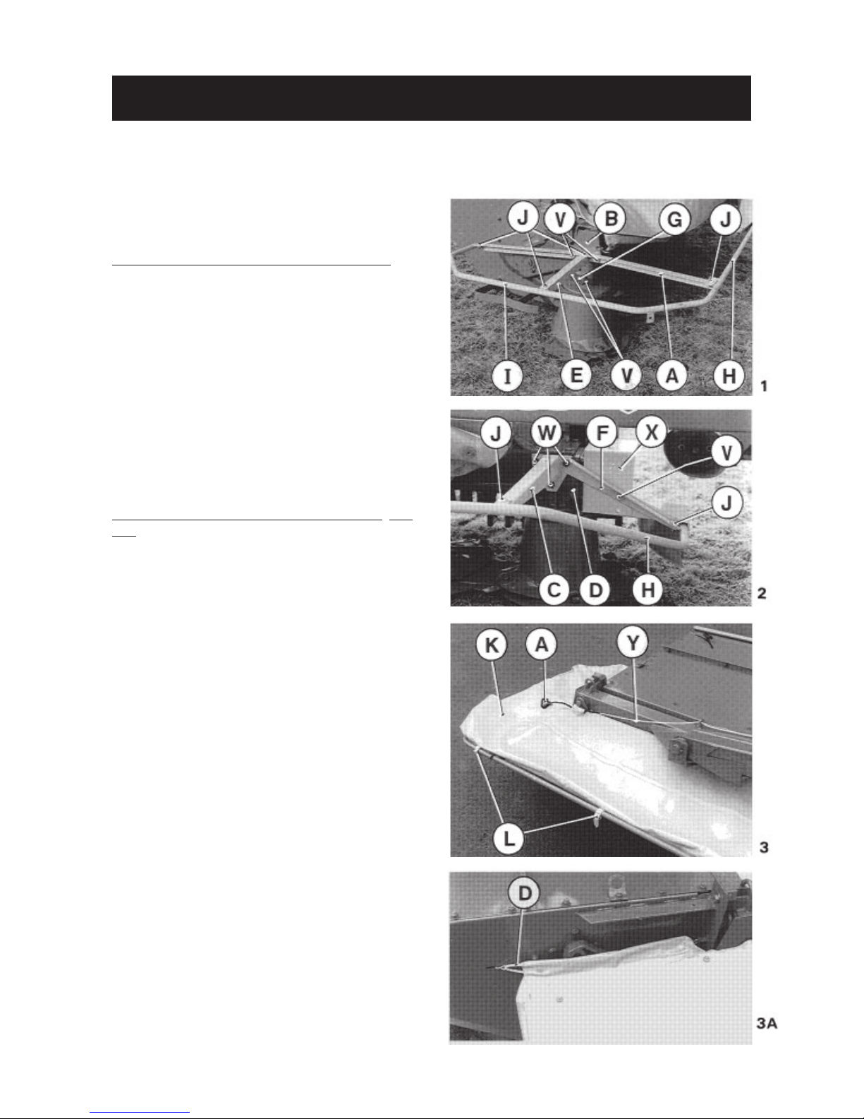
To facilitate transportation, a certain number of parts are not fitted to the
machine.
To fit these, proceed as follows :
Assembly of guards (photos 1 and 2)
- Mount bar (A) to tube (B) and the
support arm (C) to drive tube (D).
- Secure the outer support (E) to bar (A)
and the inner support (F) to the support
arm (C) and guard (X).
- Mount the tie rod (G) to outer support
(E) and tube (B) as shown in photo 1.
V = screw M12x25 + washer + nut M12
W = screw M12x25 + washer
- Fit the front guard (H) and side guard
(I) using 5 special screws M10 x 25 +
washer 11 x 24 x 2, + self-locking nut
M10 as shown in photos 1 and 2.
Assembly of safety covers (photos 3 and
3A)
Unroll cover (K) and secure to the guard
tubes using straps (L) (photo 3).
Fit cord (Y). To do this, attach one end
of cord to the end of sliding lock (B)
(photo 4), thread through the eyelets
and attach handle (A) to the other end
(thread the cord through the handle and
tie a knot (photo 3).
Next attach safety covers together using
strap (E) (see photo 27 and fig. 28 on
page 18) and hook tensioner (D) on both
side shields as shown in photo 3A.
ASSEMBLY INSTRUCTIONS
Page 15

- 13 -
Fitting the safety guards
The safety guards increase safety distance.
These guards (1, 2 and 7) should be fitted as shown in the figure below :
3 = cup square bolt M 10 x 30
4 = plain washer dia. 11 x 24 x 2
5 = self-locking nut M 10
6 = plain washer dia. 10,5 x 32 x 2,5
Fitting the rear safety guard
(only for FC 202)
Fit the rear safety guard (P) to the rear
cover (C) with 3 bolts (D) (M 10 x 25)
(see photo opposite).
Page 16

- 14 -
Fitting the shock absorber and the PTO shafts (photos 4 and 5)
Fit shock absorber (T) with washer (M 8) and self-locking nut (M 8) (photo 4).
Fit the intermediate PTO shaft (M) to the primary gearbox (N) and secure the opposite
end with strap (O) (photo 4). Attach the safety chain (P) to protection cone (Q) in
order to stop the guards of the PTO shaft from rotating (photo 4). Fit the primary
PTO shaft (R) making sure that the free wheel (overrun clutch) is fitted to the machine
side (photo 5). Attach the safety chain (S) to the 3-point frame (U). Support the
PTO shaft (R) using hook (Z) (photo 5).
Page 17

- 15 -
ATTACHMENT
Page 18

- 16 -
Page 19

- 17 -
To avoid accidents which could be serious, always check that the safety
guards are firmly in place and to prevent their rotation, attach the free
end of the safety chain to a fixed point (photos 4, 5 & 6). Replace
immediately worn or damaged guards, using genuine KUHN parts.
I.
WORKING POSITION
Once at the place of work, the machine
should be lowered to a height of 25 cm
(10") from the ground and changed from
transport to its working position as
follows :
- Release the pivot restraint (M) by
removing locking pin (S) (photo 15).
- Locking pin (S) should then be fitted
in the second hole of the stop (L)
(photo 15).
- Pull cord (E) in order to free position
lock (F) and swing the machine forward
until it locks automatically into the
working position (photo 15).
Never stand between machine
and tractor when swinging machine from transport to work
position. Make sure there is
nobody between tractor and
machine during this operation.
Lower the machine to the ground and raise
lock (G) to release the spring
compensating system (H) (photo 16).
Adjust the tractor lower link arms (W &
W’) (photo 6, page 15) if necessary so
that the chassis of the 3-point frame is
parallel to the ground.
Raise the hydraulic lift linkage so that
the lower right-hand link pin is
approximately 50 cm (20") above the
ground. Connect the support chain (B) in
the highest possible hole position of
the attachment bracket (T) of the
tractor (photo 16).
Completely lower the tractor linkage.
Lenght adjustment is correct when :
- The cutterbar is resting on the ground.
- The chain (B) is tight.
- The right-hand lower link is
approximately 45 cm (18") from the
ground.
- The 3-point frame is horizontal and
vertical (square tube ‘K’).
- The left-hand lower link (I) is
approximately 55 cm (22") from the
ground.
Attention : Close the eye of support
chain (B) using roll pin
(photo 16).
WORKING POSITION AND ADJUSTMENTS
Page 20

- 18 -
Optimal working position is obtained when the support (K) (photo 16) is in the vertical
position and when the stop (L) is positioned in the middle of its stroke (photo 15).
If necessary, adjust tractor top link.
To finish, connect the intermediate
PTO shaft (N) to the secondary gearbox (D) (photo 17).
II. ADJUSTMENT OF DOWNWARD PRESSURE OF CUTTERBAR AND CONDITIONING UNIT ON THE GROUND.
The downward pressure of the cutterbar and conditioning unit on the ground is
determined by the two suspension springs (O & O’) (photo 18) and correspond to a length
P = 60 mm (2 3/8") (photo 18).
The operator can, however, modify this setting slightly when working in extreme
conditions :
- soft and very wet ground :
reduce the downward pressure
of the cutterbar, reduce length
P.
- Very uneven land or working
at high speed : increase the
downward pressure of the
cutterbar, increase length P.
Adjustments should be carried
out with the cutterbar resting
on the ground and by adjusting
screws (O & O’) (photo 18). Do
not forget to retighten the
lock nuts (R & R’) (photo 18).
IMPORTANT : When operating the machine without the conditioning unit,the
compensating spring (O’) must be removed and length P adjusted to 100 mm
(4") for working in normal conditions.
The correct downward pressure of the cutterbar and conditioning unit will
prolong the life of the machine.
Page 21

- 19 -
III. CUTTING HEIGHT
Cutting height adjustment changes the
angle (S) of the cutterbar in respect to
the ground (fig. 20). This is done by
changing the length of the top link (V)
(photo 19).
When working in normal conditions, the
length of the top link should be adjusted
so as to have an angle (S) of about 6@
which corresponds to a cutting height of
5 to 7 cm (2" to 2 3/4"). When it is
required to cut lower, the length of the
top link should be shortened.
When it is required to cut higher,
increase the length of the top link. This
is recommended when working in rough
conditions.
When it is required to cut higher still,
replace the 4 wear plates initially
mounted on the FC with 4 raised wear
plates supplied with the machine for
this purpose.
IV. SAFETY BREAKAWAY.
In rough field conditions the ground
speed should be reduced. The machine is
protected with a safety breakaway and if
an obstruction is encountered the unit
must swing to the rear. The resistance
of the breakaway is determined by the
spring washer length which must be
positioned as shown in fig. 21.
The nominal length (Y) should be 73 mm
(3") but this length can be adjusted as
necessary to suit the varying conditions.
NOTE : DO NOT OVERTIGHTEN.
To reset the machine, reverse the
tractor.
Page 22

- 20 -
V. BELT TENSIONING
RETIGHTEN THE DRIVE BELTS AFTER
THE FIRST HOUR OF OPERATION.
TO PREVENT PREMATURE BELT WEAR,
TENSION MUST BE CHECKED
REGULARLY.
On FC 202 :
Tighten or loosen the belts (X) using
self-locking nut (U) which adjusts the
position of belt tensioner (V) (photo
22).
On FC 202 R :
Loosen the four nuts (L), then tighten
or loosen belts (X’) using screw (M)
(photo 22A). Retighten nuts (L) after
belt tension adjustment.
Drive belts must not be changed
individually. Belts must only
be fitted as a complete set (nr
831 017 64).
Loosen the drive belts when not using the
machine for long periods.
The drive belts act as a safety device which will slip should the machine
become blocked. Should this occur, stop immediately, stop the tractor
engine and clear the blockage. Always check the correct tension of the drive
belt.
Make sure that the guard (W) of the drive belts is always in place. This
guard has been raised in photos 22 and 22A for clarity of explanations.
VI. SWATH BOARDS
To increase the drying rate, the swath should be as wide as possible, leaving
sufficient clearance for the tractor wheels. This is so that the crop can get maximum
benefit from the sun and wind. It will be found that the conditioning effect is reduced
when a narrow swath is formed.
The swath width is adjustable from 0.70
m to 1.3 m (27" to 51") by means of two
swath boards which can be secured in the
desired position using knobs (Z) (photo
23).
The rear deflector (F) shapes the swath,
depending on the density of crop. After
adjustment, secure it in desired position using two lock-handles (G) (photo
23 and fig. 29 and 31).
Page 23

- 21 -
I. TRANSPORT POSITION
To change the machine from working
position to transport position, proceed
as follows :
- With the machine resting on the ground
and the tractor engine turned off,
disconnect the intermediate PTO shaft
(M) from the secondary gearbox and
secure with straps (O) (photo 4, page
10).
- Raise the FC 202 or FC 202 R to about
25 cm (10") above the ground.
- Lower lock (G) into the locked position
to secure the spring compensating system
(photo 24A).
- Standing at the right-hand side of the
machine, pull cord (E) to release lock
(F) (photo 15, page 13).
- Swing the unit to the rear until it
locks automatically into the transport
position (photo 25).
- Lock the pivot restraint (M) using the
locking pin (S) (photo 24B).
ALWAYS KEEP CLEAR OFF THE
MACHINE WHEN SWINGING THE MOWER
CONDITIONER INTO ITS TRANSPORT POSITION.
Never transport the machine on
the public highway when in the
working position, even over
short distances.
Never engage the PTO shaft of
the tractor when the machine
is in the transport position.
Using tractors smaller than 51
KW (70 HP), front ballast
weights should be used to
improve steering. For adequate
positive steering, there should
be at least 20% of the total
weight on the front axle.
Before taking the unit onto
the public highway, the
operator should make sure that
his machine conforms to the
highway code.
TRANSPORT AND PARKING POSITION
Page 24

- 22 -
The cutterbar must always be in contact
with the ground and all safety guards and
covers in place before starting to
operate the bar. It is advised that new
machines are run for 30 minutes before
being put into work to allow the parts
to run in gradually.
After a short operation at low revs, stop
the machine, turn off the tractor engine
and inspect the complete machine to see
that all nuts and bolts are still tight,
that non of the bearings are overheating
and that all parts are operating
correctly.
Before starting to cut, lower the
cutterbar to the ground and check that
all safety guards and covers are in place
and that the protection covers are
correctly secured and fastened together
with straps (L) (photo 3, page 11) and
strap (E) (photo 27 and fig. 28).
Before putting the machine into the
crop, engage the PTO of the tractor and
progressively increase its speed
(rotational frequency)
. Do not start
cutting until the machine has reached
full operating speed
(rotational
frequency)
[540-620 rpm
(min-1)
]. For
safety measures, take care to keep all
persons well clear of the machine. Do not
be disturbed by the high pitched whine
of the discs and conditioning fingers,
this will be considerably reduced when
cutting.
Ensure that the knives are sharp, especially when cutting dry, fine or sparse grass.
Should soil build up in the front of the cutterbar, reduce the downward pressure of
the cutterbar by increasing the tension of the compensating springs (O & O’) (photo
18, page 14).
II. PARKING POSITION
- Put the stand (D) in parking and
attachment position using the spring
cotter pin (A), as shown in photo 26.
- Lower the machine to the ground and
remove from tractor.
When the primary PTO shaft is disconnected
from the tractor, it should not rest
on the ground but be held by the hook
(Z) (photo 5, page 10).
Removal of the machine from tractor must only be undertaken when the machine
is in the transport position otherwise damage will be caused to the mower
conditioner.
OPERATION
Page 25

- 23 -
In very dense and wet crops where it is necessary to reduce the forward speed, it
is essential that the revs of the tractor engine are maintained to allow the discs
and the conditioning rotor to turn at a speed necessary to operate correctly.
Never adjust, lubricate, clean or unclog machine while it is operating.
Stop tractor engine first.
NEVER MOW IN STONY OR ROCKY GROUNDS.
Check the tightness of all nuts and bolts 2 to 3 hours after the initial use of the
machine, in particular those securing the discs, knives and flails.
The interior of the machine must be cleaned at regular intervals,. Remove soil which
may have become stuck to the conditioning rotor (FC 202) or rollers (FC 202 R) or
to the cover. It is in your interest to keep the machine clean.
Always disconnect the primary PTO shaft when cleaning the conditioning unit.
Ensure that FC 202 R conditioning rollers or FC 202 free swinging fingers of the
conditioning rotor are always kept in good working order.
PARTS SUPPLIED WITH THE MACHINE
A box containing one set of standard replacement knives, a quantity of blade bolts,
nuts, one 8 mm allen key, one 10 mm alley key, a 18 mm box spanner (wrench) and a
set of four raised skids are supplied with the machine.
MAINTENANCE
Page 26

- 24 -
I FC 202 (machines fitted with conditioning rotor complete with free swinging fingers
and an adjustable comb).
1. ADJUSTING THE COMB
The amount of conditioning is governed by the intersection of the flails and comb.
The comb, which is located above the rotor, has 5 different positions.
When in position 1, there is minimal conditioning effect (fig. 29).
When in position 5, there is maximum conditioning (fig. 29).
The comb is reversible and has 2 different conditioning surfaces.
2. REVERSING THE COMB SIDES (see removing the comb).
Natural grass, use with the pointed Legumes, delicate crops, clover,
side of comb towards the front of the lucerne (alfalfa), use round side
machine. of the comb.
The previous settings are a guide and not necessarily correct for each crop.
CONDITIONING
Page 27

- 25 -
3. REMOVING THE COMB
Unscrew the wing nuts (5) and open the comb cover (1) (photo 30).
Remove screw (2) securing the comb to the adjusting lever. Slide the lever (3) in
direction indicated by arrow. Remove the comb (4) and turn it over (photo 30).
Reassembly of the comb is a direct reversal of the aforementioned procedure.
RECOMMENDED SETTINGS AND OPERATION
Select the correct side of the comb for the particular crop. Make a short test run
with the comb in position 5 (maximum effect), check the result for correct
conditioning without excessive damage. If this is not the case, select another
position until the correct conditioning is achieved.
- Grass : the heads should not be separated, the stalks should be bruised but not
cut.
- Mixed grass and clover : bruising should be confined to the stalks. When cutting
takes place after the flower appears, the loss of the flowers should be kept to a
minimum.
- General rules : when cutting early in the day and requiring a moisture content
of 35% - 64% for silage barn drying, a severe conditioning effect can be used and
leaf losses will only be 2 - 4%.
Page 28

- 26 -
II FC 202 R (machines fitted with conditioning rollers)
Conditioning intensity is determined by the amount of pressure exerted on the crop
by the upper roller (A) and lower roller (B) (fig. 31 and photo 32).
This pressure is determined by adjustment of self-locking nut (C) only.
Spacer (D) is fitted with loctite and as such acts as an adjustment stop.
Pressure as set at factory : approximately 2.5 kg/cm (14 lbs/inch).
- Minimum pressure : 0 kg/cm
- Maximum pressure : 5 kg/cm (28 lbs/inch)
- Roller speed
(rotational frequency)
: 810 rpm
(min-1)
The side plate bolt stop (H) (photo 33) is only used to adjust parallelism and
clearance (E) between the two conditioning rollers (A and B) (fig. 31). Clearance
(E) is set at factory for normal operating conditions.
After adjusting bolt (H) do not forget to retighten lock nut (I) (photo 33).
The FC 202 R is fitted with lateral deflectors (O) (fig. 31) which can be removed
for improved swath form, depending on density and height of crop.
Page 29

- 27 -
SECURING DISCS AND KNIVES
Page 30

- 28 -
INSPECTION OF KNIVES AND SECURING
ELEMENTS
Page 31

- 29 -
Page 32

- 30 -
It is imperative that the oil in the gearboxes and cutterbar is changed after the
first 10 hours of use. Check that the pressure relief valves are free to operate
and not seized up. The oil level should be checked at least before and after every
season of use or after 50 to 100 ha (125 to 250 acres) of cutting. It is recommended
to change the oil at least once a year or every 100 hours of use.
IMPORTANT : Oil quantities
Liters Imp.pts US pts
Primary gearbox (photo 38) : SHELL SPIRAX 80 EP 0.75 1.32 1.58
Secondary gearbox (fig.39) : SHELL SPIRAX 80 EP 0.75 1.32 1.58
Cutterbar (fig. 40) : SHELL SPIRAX 80 EP 1.40 2.46 2.96
A = Drain plug O = Level control (verify cutterbar
F = Filler plug oil level when in the horizontal
X = Pressure relief valve position).
The above recommendations must be strictly respected.
Cutterbar overfilling leads to pressure build up and oil overheating which can
provoke serious damage to the cutterbar.
Note : If, when checking oil level, there is a doubt as to the quantity
of oil contained in the cutterbar, drain cutterbar oil completely and
refill with the correct quantity.
Before draining the cutterbar, it is essential to let it run for 10
minutes so that the oil warms up.
LUBRIFICATION
Page 33

- 31 -
NOTE : To drain the cutterbar, first let the bar turn for 10 minutes so that the oil
warms up. Remove end plate (fig. 35) and tilt the cutterbar so that the oil
can run out freely.
Grease the following pivot points every 20 hours with SHELL Multi-Purpose grease NLGI
grade 2 :
- Horizontal pivot - chassis (U) (photo 15).
- Vertical pivot - chassis (U) (photo 15).
- Lower left-hand link bracket - 3-point frame (Z) (photo 6).
- Pulley pivot - drive belt self-tensioner (V) (FC 202) (photo 22).
- Bearings and drive chains of conditioning rollers (4 grease nipples) (FC 202 R).
The bearings are located at the ends of the conditioning rollers.
Note : The gearbox of the upper roller drive (FC 202 R) ist greased for life.
Oil all pivot and articulation points every day of operation.
PTO SHAFT
Grease the PTO shaft with SHELL Multi-Purpose grease NLGI grade 2 at the hourly
intervals indicated (fig. 41).
ATTENTION : These times have been calculated for working in normal conditions. If
the conditions are abnormal or severe, grease more often.
FOR TROUBLE FREE OPERATION OF YOUR MACHINE, WE RECOMMEND THE USE OF SHELL PRODUCTS.
Page 34

- 32 -
I) RIGIDIFIED BLADES (Fig. 42)
(ref. 564 516 00)
We recommend to use the rigidified
blades for mowing in difficult conditions. They must be fitted in place of
the standard blades.
II. SIGNALLING ELEMENTS
(Kit No. 108 6590)
According to the legislation of a given
country, this kit may either be supplied
as standard equipment, or be available
as an optional extra.
To install the kit, proceed as
follows :
- Attach the rear warning board (P) to
the box section frame end plate (T)
with two hexagon bolts (H)(M10x20), 2
plain washers (dia 11x24x2) and two
self-locking nuts (M10) as shown in
photo 43.
- Attach tail lamp (R) to warning board
(P).
- Lay out wiring harness as shown in
photos 43 and 44 and fix onto frames (T)
and (N) with clamp collars and their
self-sticking supports (A). Avoid situations where the cables can be trapped
or stretched.
- Attach plug holder (L) to 3-point frame
(N) with 2 screws (M)(M6x30) and 2
self-locking nuts (M6)(photo 44).
NOTE : - The signalling element kit re-
quires a 7 pin socket at the
rear of the tractor.
- When detaching the implement,
place plug (E) in holder
(L)(photo 44).
OPTIONAL EQUIPMENT
Page 35

- 33 -
III. ADDITIONAL SUSPENSION SPRING
FOR FC 202 R
(Kit No. 108 6660)(photo 45)
The additional compensating spring balances the extra weight of the roller
conditioning unit assuring smooth floatation even when working on soft terrain.
To install the kit proceed as follows.
- Remove the existing compensating
springs.
- Attach central spring with shock absorber (C) to lower support (I) with
pin (G) and 2 cotter pins (dia 5x22).
- Hook both lateral springs (L) to lower
support (I) and attach them to the
upper support (S) with 2 hexagon bolts
(K)(M16x30) and 2 spring washers (M16).
- Bolt the lower support with installed springs to the lower hitch yoke (O) using
the hexagon bolt (U)(M16x120) and a self-locking nut (M16).
- Apply grease to one of the original two M16x210 bolts (Y) and screw this bolt onto
the central spring to attach the upper supports (S) to upright (V) of the 3-point
frame. Do not forget to put lock nut (W) over the upper support and spring washer
(dia 16 mm) under bolt head (Y).
Cutterbar down pressure is adjusted by rotating bolt (Y) after loosening lock nut
(W). It should be adjusted in such a way that the left or right side of the header
can be raised off the ground with a force of 50 daNm, which corresponds to a weight
of 50 kf/110 ft.lbs. Retighten lock nut (W) after setting down pressure.
Page 36

- 34 -
END OF SEASON SERVICE
To ensure best performance at the
beginning of the next season, take the
mower conditioner to your Kuhn dealer
for an inspection and any necessary
service work at the end of each season.
1. Store the mower conditioner in a dry
place.
2. Clean the mower thoroughly inside and
outside. Trash and dirt will draw
moisture and cause rust.
3. Thoroughly lubricate the machine
according to the lubrication section
(see pages 30 & 31).
4. Paint all parts from which the paint
has worn.
5. Loosen the drive belts and at the same
time check their condition. Replace
the complete set if necessary (see
page 20).
6. Check the condition of the knives,
turn them over to use the second
cutting edge if necessary. Check that
there is no missing flails on the
conditioning rotor (FC 202).
7. List the replacement parts that will
be needed and order them early. The
dealer at this time can expedite
delivery of parts and install them
during slack periods, thereby avoiding delays for the next season.
Attention : Check the condition of all safety guards and
covers. Replace if worn or
damaged.
BEGINNING OF SEASON SERVICE
1. Check the oil levels (see page 30).
2. Grease the complete machine as described on pages 30 & 31 to force out
any collected moisture out of the
bearings.
3. Retighten the drive belts as described on page 20.
4. Check the tightness of all nuts and
bolts.
5. Check the adjustment of the safety
breakaway (page 19).
6. If any major moving parts have been
replaced, they should be run in.
7. Review your operator’s manual.
STORAGE
Page 37

- 35 -
The majority of operating problems that occur with the mower conditioner can be traced
to improper adjustment or delayed service. The following chart has been designed to
help you when a problem develops by suggesting a probable cause and the recommended
solution.
These suggested remedies should be applied with caution. Make certain the source of
the problem is not located in an area different from the one where it showed. A thorough
understanding of the machine is indispensable for the correction of operating
problems.
PROBLEM POSSIBLE CAUSE REMEDY
Excessive vibration - Conditioning rotor out of - Control number of mo-
balance. vable fingers.
- Parallelism of conditioning - Adjust roller parallerollers badly adjusted. lism with lateral bolt
stops (H) (fig.33 pg 22)
- Conditioning roller(s) - Replace conditioning
deformed. roller(s).
Damaged leaves and - Incorrect comb position - Raise the comb position
broken stems or invert the comb.
Obstruction of - Engine speed
(rotational
- Correct PTO speed
rotor or of
frequency)
too low
(rotational frequency)
to
conditioning 540 rpm
(min-1)
rollers - Drive belt slipping or - Tighten or replace the
broken belt. Check if idler is
correctly centered
between pullies.
Obstruction of - Bent or broken knives - Replace knives
cutterbar - Wet crop conditions on - Increase cutting height
clayey ground (earth by reducing platform
plugging). pitch.
- Fit set of high skid shoes.
Ragged cut - Knives incorrectly fitted - Check if knives are
correctly fitted (see
arrow).
- Dull knives - Reverse or replace knives.
- Excessive ground speed - Reduce ground speed
- Incorrect platform floa- - Adjust platform weight
ting (page 18).
- Incorrect cutting height - Change cutterbar pitch
or the wear plates
- Incorrect cutterbar pitch - Change cutterbar pitch
- Down crop - Increase platform weight
Badly shaped - Incorrect setting of - Adjust windrow deflectors
windrow windrow deflectors or of or rear deflector.
rear deflector.
TROUBLE SHOOTING
Page 38

- 36 -
PROBLEM POSSIBLE CAUSE REMEDY
Strips of uncut - Broken knives - Replace knives
material left on - Foreign objects on - Disengage tractor PTO
field cutterbar shut off engine, wait
until all parts have
stopped & remove foreign
objects, vegetation or
soil.
- Wet conditions - Reduce cutterbar weight
Frequent breakage - Cutterbar set too low for - Adjust cutterbar by
of knives work on rugged & uneven changing angle or fit
soil high skids.
- Excessive ground speed - Reduce ground speed
V-belt breakage - Rotor vibration - Check for correct number
of comb tines or check
rotor bearings (FC 202)
- Check parallelism of conditioning rollers (FC 202R)
- Downward pressure of - Check for correct
adjustment
cutterbar and conditioning of downward pressure of
unit on the ground badly cutterbar and conditioning
adjusted. unit on the ground
(see page 18).
Page 39

- 37 -
SOUND LEVELS
Sound levels given out by : FC 202 - FC 202 R Mower conditioners
Sound levels have been measured in accordance with the measuring methods as defined in :
HM Agricultural Inspectorate
AGRICULTURAL MACHINERY NOISE
Legislation and guidance on methods of testing
(Annex to AIC 1896/117 REV)
February 1988
Health and Safety Executive
The method employed corresponds to the method No. 4 in this document. Unspecified testing
conditions comply with ISO 5131 standard.
Measuring equipment conforms to NF S 31-009 standard. The tractors used have a power of 59 kW
(FC 202) and 76 kW ( FC 202 R) respectively.
A-weighted emission sound pressure level L (A) eq inside tractor cab (with closed windows) :
FC 202 FC 202 R
Tractor only 79.9 dB (A) 73.3 dB (A)
Tractor + machine 81.4 dB (A) 75.6 db (A)
Page 40

LIMITED WARRANTY
KUHN S.A. of 4 Impasse des Fabriques, 67706 SAVERNE CEDEX, France (hereinafter called the
«Company») warrants, in accordance with the provisions below, to each original retail purchaser of
KUHN new equipment of its own manufacture, from an authorized KUHN dealer, that such equipment
is, at the time of delivery to such purchaser, free from defects in material and workmanship and that
such equipment will be warranted for a period of one year starting from the date the goods are delivered
to the end user and during this period up to a limit of 500 hours use, providing the machine is used and
serviced in accordance with the recommendations in the Operators Manual.
THESE CONDITIONS ARE SUBJECT TO THE FOLLOWING EXCEPTIONS :
1. Parts of machines which are not of our manufacture i.e. tyres, belts, P.T.O. shafts, clutches etc., are not
covered by this Limited Warranty but are subject to the warranty of the original manufacturer. Any claim
falling into this category will be taken up with the manufacturer concerned.
2. Warranty claims applying to these types of parts must be handled in the same way as if they were parts
manufactured by KUHN. However, compensation will be paid in accordance with the warranty agreement of the manufacturer concerned in as much as the latter justifies such a claim.
3. This Limited Warranty will be withdrawn if any equipment has been used for purposes other than for
which it was intended or if it has been misused, neglected or damaged by accident or let out on hire. Nor
can claims be accepted if parts other than those manufactured by us have been incorporated in any of
our equipment. Furthermore, the Company shall not be responsible for damage in transit or handling by
any common carrier and under no circumstances within or without the warranty period will the Company
be liable for damages for loss of use or damages resulting from delay or any consequential damage.
We cannot be held responsible for loss of earnings caused by a breakdown or for injuries either to the owner
or to a third party, nor can we be called upon to be responsible for labor charges, other than originally
agreed, incurred in the removal or replacements of components.
THE CUSTOMER WILL BE RESPONSIBLE FOR AND BEAR THE COSTS OF:
1. Normal maintenance such as greasing, maintenance of oil levels, minor adjustments, etc.
2. Transportation of any kind of any KUHN product to and from the place the warranty work is performed.
3. Dealer travel time to and from the machine or to deliver and return the machine from the workshop for
repair.
4. Dealer travelling costs.
Parts defined as normal wearing items are listed as follows and are not in any way covered under this
Limited Warranty :
V belts, discs, knives, wear plates, disc guards, tires, torque limiters, hydraulic hoses, pitman shafts, swath
sticks, blades, tines and tine holders.
KUHN Limited Warranty will not apply to any product which is altered or modified without the expressed
permission of the Company and/or repaired by anyone other than Authorized Service Distributors or
Authorized Service Dealers.
Page 41

LIMITED WARRANTY IS DEPENDENT UPON THE STRICT OBSERVANCE BY THE
PURCHASER OF THE FOLLOWING PROVISIONS :
- That this Limited Warranty shall not be assigned or transferred to anyone unless the Companys consent in
writing has first been obtained.
- The warranty/product registration form has been correctly completed by dealer and purchaser with their
names and addresses, dated, signed and returned to the appropriate address as given on the warranty/
product registration form.
- The claim form sent to KUHN has been correctly completed stating:
* dealers name and address
* owners name and address
* type of machine
* machine serial number
* delivery date to buyer
* date of failure
* tractor make and type
* description of the failure and its cause
* quantity, reference number and name of the damaged parts
* reference number, quantity and date of the invoice for the replacement parts.
- The judgement of the Company in all cases of claims under this Limited Warranty shall be final and conclusive and the purchaser agrees to accept its decisions on all questions as to defect and to the exchange of
any part or parts.
- That all safety instructions in the Operators Manual shall be followed and all safety guards regularly inspected
and replaced where necessary.
No warranty is given on second-hand products and none is to be implied. Persons dealing in the Companys
products are in no way legal agents of the Company and have no right or authority to assume any obligation
on their behalf, express implied, or to bind them in any way.
KUHN S.A. reserves the right to incorporate any change in design in its products without obligation to make
such changes on units previously manufactured.
Moreover, because of the constant progress in technology, no guarantee is given to the descriptions of
equipment published in any document by the company.
DISCLAIMER OF FURTHER WARRANTY
There are no warranties, expressed or implied, except as set forth above. There is no
warranty of merchantability. There are no warranties which extend beyond the description
of the product contained herein. In no event shall the company be liable for indirect, special
or consequential damages (such as loss of anticipated profits) in connection with the retail
purchasers use of the product.
Page 42

- N O T E S -
Page 43

This machine complies with the safety requirements of the European machinery directive.
The Operator should respect all Health and Safety regulations as well as the Highway
Code. For your own safety, use only genuine KUHN spare parts. The manufacturer
disclaims all responsibilities due to incorrect use or non-compliance with the
recommendations given in this manual.
Page 44

Printed in France by KUHN
KUHN S.A. 4 Impasse des Fabriques F - 67706 SAVERNE CEDEX (FRANCE)
Tél. : + 33 (0) 3 88 01 81 00 - Fax : + 33 (0) 3 88 01 81 03
www.kuhnsa.com - E-mail : info@kuhnsa.com
Société Anonyme au Capital de 19 488 000 Euros
For your safety
and to get the best from your machine,
use only genuine KUHN parts
 Loading...