

Page 1
OPERATOR'S MANUAL
POWER TILLER EL 35
N° 95452 A.GB - 09.97
Page 2
DEAR OWNER,
In buying a KUHN machine you have chosen wisely. Into it have gone years of thought,
research and improvements. You will find, as have thousands of owners all over the world, that
you have the best that engineering skill and actual field testing can produce. You have
purchased a dependable machine, but only by proper care and operation can you expect to
receive the performance and long service built into it.
This manual contains all the necessary information for you to receive full efficiency from your
machine. The performance you get from this machine is largely dependant upon how well you
read and understand this manual and apply this knowledge. Please DO NOT ASSUME THAT
YOU KNOW HOW TO OPERATE AND MAINTAIN YOUR MACHINE before reading this
manual carefully. KEEP THIS MANUAL AVAILABLE FOR REFERENCE.
Your KUHN dealer will instruct you on the general operation of your machine. He is interested
that you get the best performance possible and will be glad to answer any special questions
that may arise regarding the operation of the KUHN machine.
Your KUHN dealer can offer a complete line of genuine KUHN service parts.
These parts are manufactured and carefully inspected in the same factory that builds the
machine to assure high quality and accurate fitting of any necessary replacements.
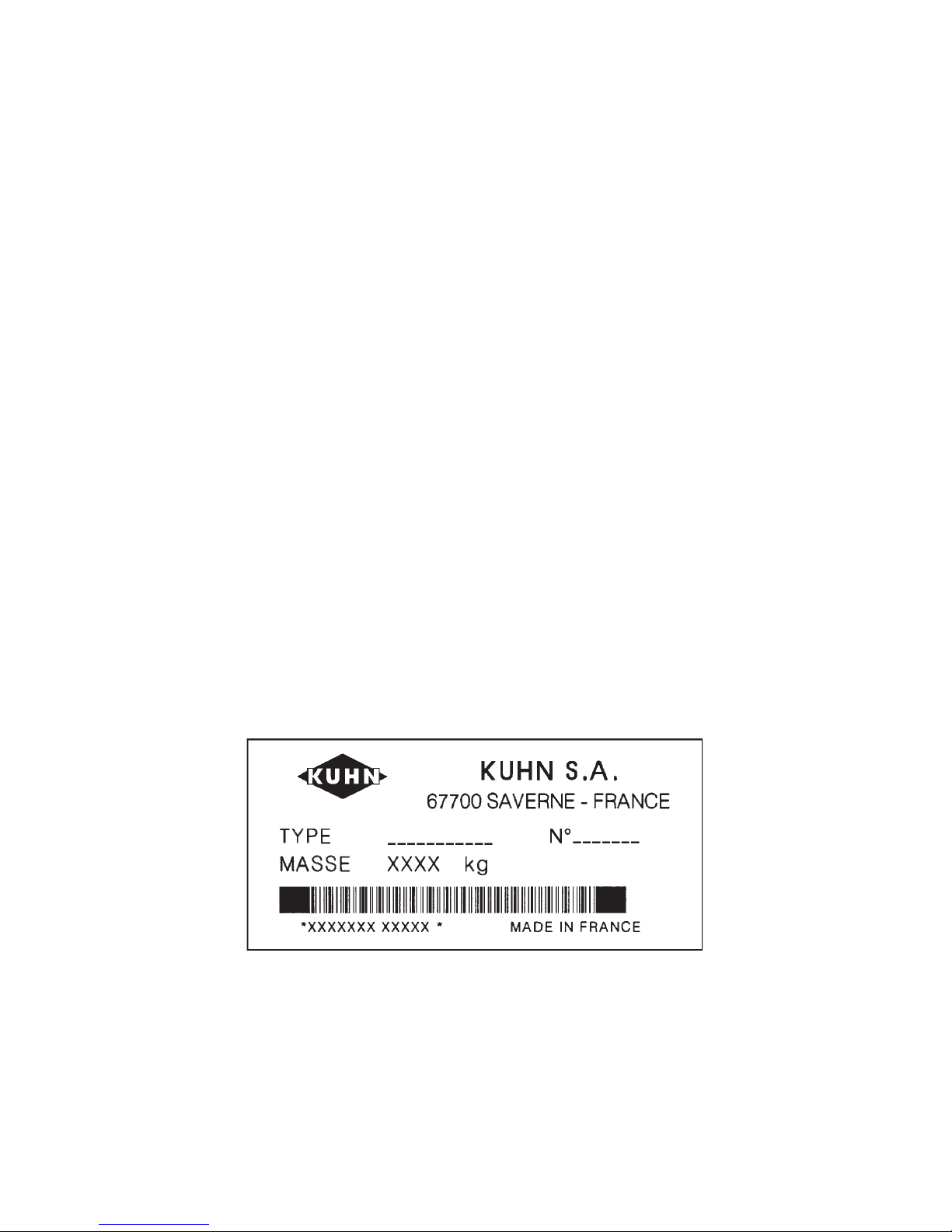
When ordering service parts it is important that you indicate the type of machine concerned
and its serial number.
For this reason please complete the model identification plate diagram below with the required
information. This will provide you with an easy reference for future service parts orders.
ABOUT IMPROVEMENTS
KUHN is continually striving to improve its products and, therefore, reserves the right to make
improvements or changes when it becomes practical to do so, without incurring any
obligations to make changes or additions to the equipment sold previously.
Page 3

- 1 -
CONTENTS
Page
Safety 2
Safety decals 7
Technical specifications 9
Safety guards 10
Off-setting 13
Fitting to the tractor 14
P.T.O. shaft 15
Rotor speed 17
Use 17
Optional accessories 19
1° Gauge wheel kit 19
2° Skids + Stand 19
3° Slip clutch 20
4° P.T.O. shafts 20
Maintenance 21
1° Lubrication 21
2° Fitting blades 22
Trouble shooting 23
Conditions of limited warranty 24
Copyright 1997 KUHN S.A.
Page 4

- 2 -
SAFETY
The above symbol is used throughout this manual every time recommendations are made concerning your
safety, the safety of others, or the good operation of the machine.
These recommendations must be made known to all machine operators.
DESIGNATED USE OF THE MACHINE
The EL 35 must only be used for the work for which they have been designed :
- Seedbed preparation on ploughed or unploughed ground.
- Stubble ploughing or reclamation of grassland.
- Orchard and vineyard cultivation.
The manufacturer is not held liable for any damage resulting from machine applications other than those specified
by the manufacturer.
Any use other than the designated operation is at the risk and responsibility of the operator.
Designated use of the machine also means :
- following operation, maintenance and repair recommendations given by the manufacturer ;
- using only genuine spare parts, equipment and accessories as designated by the manufacturer.
The EL 35 must only be operated, maintained and repaired by competent persons who are familiar with machine
specifications and operations and are aware of any danger involved.
The operator must imperatively respect current legislation concerning :
- accident prevention,
- work safety,
- public traffic circulation.
All safety advice indicated on the machine must be strictly observed.
The manufacturer is not held liable for any damage resulting from machine modifications carried out by the
operator himself or by a third party without previous written agreement from the manufacturer.
Page 5

- 3 -
GENERAL SAFETY RECOMMENDATIONS
Before operating the machine, always ensure that tractor and machine meet with work safety and road traffic
regulations.
BASIC PRINCIPLES
1. In addition to the recommendations given in this manual, legislation on work safety and accident prevention
must also be respected.
2. Advice is indicated on the machine, specifying safety recommendations in order to prevent accidents.
3. Before travelling on public roads, the operator must ensure that the machine conforms to road traffic
regulations.
4. Before starting work, the operator must be familiar with all machine controls, handling devices and their
functions. Once at work, it is too late to do this !
5. Do not wear loose clothing which could become caught up in moving elements.
6. Use a tractor equipped with a safety cab. Keep windows and roof hatch closed for reduced sound level while
operating the PTO driven implement.
7. Before starting up the machine and beginning work, check the surrounding area (beware of children !). Make
sure there is sufficient visibility.
Keep all people and animals away from the danger zone of the machine (risk of projection !)
8. Carrying people or animals on the machine when working or in transport is strictly forbidden.
9. Machine must only be attached to tractor using means provided and in accordance with current safety
standards.
10. Special care should be taken when attaching or removing the machine from the tractor.
11. Before attaching the machine, ensure that the front tractor axle is sufficiently ballasted.
Ballast is to be placed on the supports provided in accordance with instructions of the tractor manufacturer.
12. Do not exceed the maximum axle load or the overall transport weight prescribed by the tractor manufacturer.
13. Do not surpass the maximum transport width authorized by road traffic regulations.
14. Before transporting the machine on public roads, ensure that all legally required guards and indicators
(lights, reflectors ...) are in place and in good operation.
15. All operating controls (cords, cables, rods...) must be positioned so that they cannot be set off accidently,
risking accident or damage.
Page 6

- 4 -
16. Before traveling on public roads, put the machine into its transport position as instructed in this operators
manual.
17. Never leave the tractor seat while the machine is operating.
18. Drive speed must be adapted to ground conditions as well as to roads and paths.
Always avoid abrupt changes of direction.
19. Precision steering, tractor adherence, road holding and efficient braking are influenced by the type of
implement, weight, ballast of front axle, ground or road conditions. It is therefore of utmost importance to
be cautious in every given situation.
20. Be particularly cautious when turning corners, paying attention to machine overhang, length, height and
weight.
21. Before operating the machine, ensure that all safety guards are firmly in place and in good condition. If worn
or damaged, replace immediately.
22. Before operating the machine, check the tightness of all nuts and bolts, particularly on fixing elements
(blades, tines, knives, spades ...)
23. Keep clear of the machine operating area.
24. WARNING ! Danger of crushing and shearing can exist when components are operated by hydraulic or
pneumatic controls.
25. Before leaving the tractor or before adjusting, maintaining or repairing the machine, turn off the engine,
remove the ignition key and wait until all moving parts have come to a complete stop.
26. Do not stand between the tractor and the machine unless the hand brake is tight and/or stops have been
placed under the wheels.
27. Before any adjustments, maintenance or repairs are carried out, ensure that the machine cannot be started
up accidentally.
ATTACHMENT
1. When attaching or removing the machine from the tractor, position hydraulic lift control lever in such a way that
it cannot be set off accidentally.
2. When attaching the machine to the tractor hydraulic linkage, ensure that diameter of the link pins correspond
to the diameter of the ball joints.
3. WARNING ! Danger of crushing and shearing can exist in the lifting zone of the tractor hydraulic linkage !
4. Do not stand between the tractor and the machine when operating the outer control lever of the lift mechanism.
5. In transport, the machine lift mechanism should be stabilized by tractor tie rods to avoid floatation and side
shifting.
6. When transporting the machine ensure that it can not be lowered accidentally.
Page 7

- 5 -
POWER TAKE-OFF
1. Use only the PTO shaft supplied with the machine or recommended by the manufacturer.
2. PTO guards must always be in place and in good condition.
3. Check for correct PTO overlap when at work and in transport.
4. Before attaching or removing the PTO shaft, disengage PTO shaft, turn off engine and remove ignition key.
5. If a primary PTO shaft is equipped with a slip clutch or a free wheel, these must be fitted on the machine
PTO.
6. Ensure that PTO shaft is always correctly fitted and locked into place.
7. Make sure guards are correctly in place and secured with the safety chains provided.
8. Before engaging PTO, ensure that PTO speed and direction are in accordance with manufacturer's
recommendations.
9. Before engaging PTO, keep all people and animals clear from the machine.
10. Never engage PTO shaft when tractor engine is turned off.
11. Never surpass the PTO angle recommended by the manufacturer.
12. WARNING ! Rotating elements can continue turning momentarily after PTO is disengaged. Keep clear until
all rotating elements are at a standstill.
13. When removing the machine, place PTO shaft on the supports provided.
14. Fit the safety cap on tractor PTO.
15. Replace any worn or damaged PTO guards immediately.
Page 8

- 6 -
MAINTENANCE
1. Before checking for any machine malfunction and before adjusting, maintaining or repairing the machine,
disengage PTO, turn off engine and remove ignition key.
2. Check nut and bolt tightness regularly. Retighten if necessary.
3. If the machine is raised, prop it up in a stable position before carrying out any maintenance work.
4. When replacing a working part, wear protection gloves and use only standardized tools.
5. It is forbidden to discard any oil, grease or filters. These must be given to waste disposal organisations to
protect the environment.
6. Disconnect power source before any work is done to the electric system.
7. Check safety guards regularly, particularly those that are subject to wear. Replace immediately if damaged.
8. Spare parts used must be in accordance with specifications and standards as defined by the manufacturer.
Use only genuine KUHN parts !
9. Before any electric welding is carried out on tractor or attached machine, disconnect generator and battery
terminals.
10. Repairs on elements under pressure or tension (springs, accumulators etc...) must only be carried out by
competent persons with standardized equipment.
Page 9
- 7 -
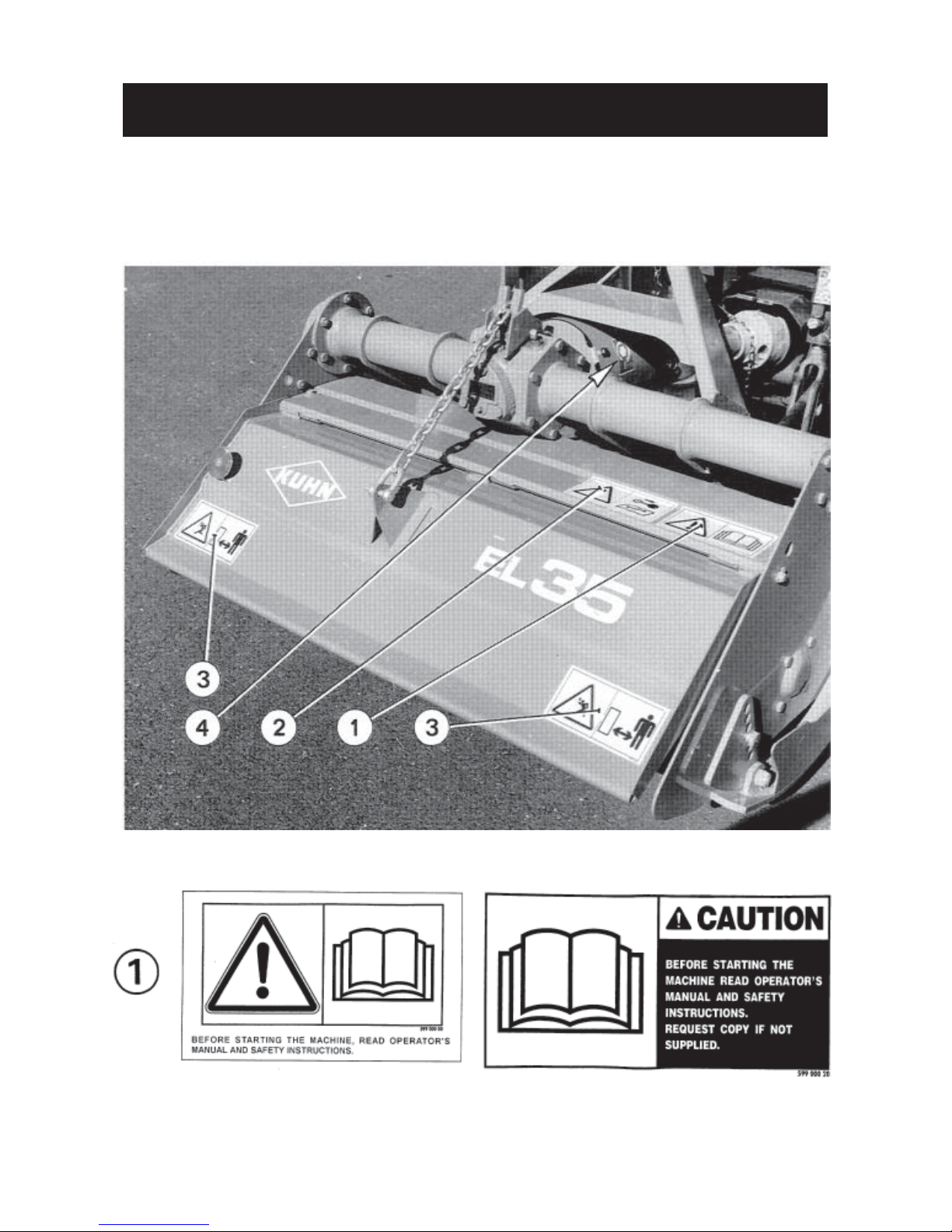
SAFETY DECALS
THE FOLLOWING SAFETY PICTORIALS HAVE BEEN PLACED ON YOUR MACHINE IN THE
AREAS INDICATED. THEY ARE INTENDED FOR YOUR PERSONAL SAFETY AND FOR THE
SAFETY OF THE PEOPLE WORKING WITH YOU. THE TEXT SHOWN ON THEM GIVES THEIR
PRECISE MEANING. KEEP THE PICTORIALS LEGIBLE. IF THEY ARE NOT, REPLACE THEM.
Page 10

- 8 -
Page 11

- 9 -
EL 35 EL 35 EL 35 EL 35 EL 35
92 105 117 130 155
Working width cm (") 92 (36") 105 (41") 117 (46") 130 (51") 155 (60")
Maximum tractor DIN power kW (hp) 26 (35)
Minimum power requirement kW (hp) 12 (16) 13 (17,5) 14 (19) 15 (20,5) 16 (22)
P.T.O. speed (rpm) 540
Rotor speed (rpm) 248
Rotor diameter mm (") 420 (16")
Number of mulch blades (3 pair formation) 21 24 27 30 36
Working depth mini / maxi cm (") 6 - 18 (2" - 7")
Working depth control with skids or gauge wheels
P.T.O. shaft standard without friction slip clutch
Off-setting to the right by 18 cm / 7" no yes yes yes yes
Attachment Cat. 1 N (narrow) - 0 - 1
Total width cm (") 108 (43") 121 (48") 133 (53") 146 (57") 171 (67")
Weight with gauge wheels kg (lbs) 196 (431) 216 (475) 226 (497) 233 (513) 256 (563)
Weight with skids kg (lbs) 186 (409) 206 (453) 216 (475) 223 (491) 246 (541)
TECHNICAL SPECIFICATIONS
TECHNICAL SPECIFICATIONS
*
*
*
see note on page 22 for proper installation
Page 12

- 10 -
SAFETY GUARDS
The safety guards protect against accidents and therefore ensure maximum machine safety.
Figures 1, 3, 7, 11 and 15 (pages 10, 11 and 12) indicate the guards factory setting for category 1N (narrow lower
link spacing) and category "O" attachments with the head stock in the central position.
This setting provides the optimal guarding whatever the machine width, hitch category and head stock position.
When using a tractor with a category 1 linkage or when coupling to a machine with the head stock in the offset
position, the guards may also be fitted as shown in figures 2, 4, 5, 6, 8, 9, 10, 12, 13, 14, 16 , 17 and 18 to increase
clearance around the lower link brackets.
However, on no account must the clearance between guards and lower attachment yokes exceed
60 mm / 2.3" (see distance D in figure 7). Lateral guard support (A and B in figure 7) must always remain
fitted.
Note : - When mounting the EL 35 - 130 headstock in the offset position remove guard (C, figure 12) and replace
it with bracket (E) supplied with the machine as shown in figure 14.
- A third angle iron (F), also supplied with the machine, must be installed as shown in figures 13 and 17
whenever the EL 35 - 130 or EL 35 - 155 is attached in the offset position to a category 1 N or category
"0" tractor.
Page 13

- 11 -
Page 14

- 12 -
Page 15

- 13 -
OFF-SETTING
(fig. 19) (only for 105 / 117 / 130 / 155)
The EL 35 Power Tiller can be mounted behind a tractor in an off-set position to the right (or in line with the tractor).
The setting of the machine in this position should be carried out before mounting to the tractor.
The offset position is obtained by removing the head stock (1) from its central position (A) and mounting it in position
(B). To avoid accidents, make sure the power tiller is properly secured before removing the head stock. Use a
hoist, lifting from the tube. Avoid using makeshift props that are unsafe.
Position A : in line Position B : 18 cm (7") off-set to the right by distance "D".
After reassembling the head stock, make sure the front safety guards are correctly fitted (see pages 10, 11 and
12).
Note :The POWER TILLER EL 35 type 92 cannot be off-set by moving the hitch frame but it is possible to obtain
adjustment of 6 to 8 cm (2 to 3 ins) by adjusting the lower link brackets.
When reassembling, make sure all bolts (V and
W) are tightened to a torque of 14 daNm
(100 ft.lbs).
Page 16

- 14 -
FITTING TO THE TRACTOR
The EL 35 has two adjustment settings giving the following attachment possibilities :
The lower link brackets are mounted symmetrically to the head stock.
*
Page 17

- 15 -
P.T.O. DRIVE SHAFT
Make sure the EL 35 is resting on the ground and is maintained in a stable position with the parking stand or with
the front wheels. Clean and lubricate the gearbox input shaft and slide the mating PTO shaft yoke in place.
After mounting the Power Tiller, stabilize the tractor 3-point linkage with whatever means are recommended (tie
bars, chains etc.).
Be sure the tractor P.T.O. shaft drive is disengaged and stop engine.
Couple the PTO shaft to the tractor P.T.O. stub.
Attachment is correct when machine is horizontal in work position.
With the machine resting on the ground, adjust the top link (P) length to a position where the tractor PTO stub
and the tiller input shaft are parallel.
In working position :
- The 2 angles (K) formed by the centre lines of the yoke and the sliding tubes must be equal and not exceed
a combined angle of 30° when working.
- The sliding tube overlap (L) must be at least 22 cm (8.5") (fig. 23).
Page 18

- 16 -
With the machine fully raised on the tractor hydraulic linkage :
- The 2 sliding tubes must not completely overlap each other ; a gap (M) of 1 cm (3/8") should exist between end
of sliding tube and yoke.
- Both U joints (K) should operate approximately at the same bent angles which must never exceed
40° (figure 23).
Should the above mentioned conditions not exist :
- Shorten both tubes by an equal length, chamfer edges and grease liberally before refitting.
- To avoid noisy running of the PTO shaft when lifting the machine out of work, attach top link (P) so that it is
almost parallel to the lower links (fig. 23).
Important : Always disconnect the tractor PTO drive before lifting the machine into the transport position,
otherwise permanent damage can be caused to the transmission shaft.
Repeat these adjustments each time the machine is mounted to a different tractor.
A safety chain (C) is delivered with the machine to
support the PTO shaft (T) when the machine is
parked. This prevents the PTO shaft from becoming
soiled or deteriorated when in contact with the ground.
Attach the chain (C) to the support (U) as shown in the
photo 24 opposite.
Always make sure the PTO shaft guards are in good condition and secured with the safety chains
provided to prevent them from turning. The safety chains should be attached to the side of the
machine at the safety guard of the central gearbox (photo 24). Replace guards immediately if they
become damaged.
Page 19

- 17 -
ROTOR SPEED
The rotor speed of the EL 35 is 248 rpm with a P.T.O. speed of 540 rpm.
No other PTO speed is allowed.
USE
BEFORE ADJUSTING, MAINTAINING OR REPAIRING THE MACHINE, TURN OFF THE
ENGINE, REMOVE IGNITION KEY AND WAIT UNTIL ALL MOVING PARTS HAVE COME TO
A COMPLETE STOP.
The tilth varies with the work required. The degree of tilth is governed by combining the following factors :
- rear shield position, regulated by suspension chain,
- forward speed,
- working depth,
- mounting of 2 or 3 pairs of blades,
- number of passes.
Coarse tilth :
- Rear shield up
- Fast forward speed (approx. 2.5 mph - 4 km/h)
- 2 pairs of blades.
Fine tilth :
- Rear shield down
- Slow forward speed (approx. 1 mph - 1.5 km/h)
- 3 pairs of blades.
Page 20

- 18 -
Hints on use :
- Allow the rotor to rotate at ist working speed before engaging it into the soil. Gradually lower the machine while
pulling forward with the tractor.
- Always work in a straight line. When turning, lift machine out of work.
- Never work in reverse, otherwise damage could occur to some component parts.
- Do not disengage the PTO drive unless the machine has been lifted out of work.
Important remarks :
Like many farm machines, the use of the EL 35 entails limits which must be respected in all situations.
These limits are often tied in with :
- meteorological conditions : avoid working during and immediately after rainfall, wait until ground to be
worked is completely drained,
- soil types : smooth clods indicate too malleable or too humid soil to be worked in. Wait until ground is
completely drained. Soil consistency is ideal when clods crumble without sticking,
- tractor power : adapt share depth, working depth and forward speed to power available and type of work
to be done.
Never exceed the maximum allowable tractor DIN power : 26 kW (35 hp).
Page 21

- 19 -
OPTIONAL ACCESSORIES
1° WHEEL ASSEMBLY - Kit No 120 6600
The EL 35 can be equipped with a gauge wheel kit to
control working depth. Wheels (R) are fitted on cross
tube (T) in front of the machine (photo 26).
The wheels (R) are adjustable :
- In height on the inside of their suport (S) using the
adjustment pin (B) (see photo 26). To avoid any risk
of accident, don't forget to install safety pins (A).
- The wheels are also adjustable sideways so that
they may be positioned in line with the tractor
wheels.
Tighten screws (U) to 14 daNm / 100 ft.lbs.
The EL 35 may also be equipped with a set of two skids to be mounted on each side of the machine for setting
and adjusting the rotor working depth. The skids are attached to the front of the machine with bolts (U) (torque
8 daNm / 60 ft.lbs) and to the rear of the machine with the holed bars (T) and bolts (U) (torque 21 daNm /
155 ft.lbs).
Depth control is adjusted by means of the holed skid bars (T) (photos 27 and 28).
A stand (E) is supplied with the skids to ensure stability when machine is parked (photo 28).
To avoid any risk of accident, don't forget to install safety pin (A) (photo 28).
2° SKIDS + STAND
Kit No 120 6840
Page 22

- 20 -
3° P.T.O. SHAFT WITH FRICTION SLIP CLUTCH (photo 29) - No 4500 402
The EL 35 can be equipped with a PTO transmission shaft complete with friction slip clutch.
The spring pressures are adjusted before delivery to
a length of 27 mm to give a correct load with PTO
speed of 540 rpm.
The theoretical length «L» of springs «R» is an
average setting and slight deviations can be made
according to working conditions and tractor engine
rating.
The springs of the slip clutch must all be equally adjusted to a setting where the implement can operate under
normal conditions without the plates slipping. However, when extreme conditions are encountered, such as
obstructions, the friction plates must slip.
IMPORTANT : * Always check if the clutch is set correctly for the work to be carried out. It should feel warm
to the touch during work.
* If the clutch slips excessively (too light a spring pressure, obstacles, etc.), readjust if
necessary and wait until the temperature of the clutch drops to a normal work temperature
of approximately 40°C (104 °F) before continuing work. If the clutch overheats it will slip more
easily, thus increasing disc wear.
* With L = 26 mm the springs (R) will be completely coil bound and the clutch cannot operate.
Never work with springs fully locked as this risks deteriorating drive line components if an
obstruction jams the rotor. Always loosen them by at least half a turn.
NEVER FULLY LOCK THE SPRINGS.
Check clutch setting regularly, especially after the machine hasnt worked for a long time. Completely slacken
off the 6 springs (R) (photo 29) by unscrewing their securing nuts, let the friction plates slip for a few seconds
then retighten springs as explained above (to L = 27 mm).
Note : For easier access when wishing to adjust the slip clutch, we strongly recommend that you firstly remove
the clutch guard. Do not forget to replace the guard after adjustment is made.
4° P.T.O. SHAFTS
The following PTO shafts are available :
- part no. 4500 400 : PTO shaft supplied as standard with the machine,
tractor end yoke : 1 3/8" - 6 splines
- part no. 4500 402 : optional PTO shaft with friction slip clutch,
tractor end yoke : 1 3/8" - 6 splines.
Page 23

- 21 -
MAINTENANCE
1° LUBRICATION
PTO transmission shaft (A) (photo 30) : Grease the telescopic tubes and universal knuckle joints every 8
hours with SHELL Multi-Purpose grease NLGI grade 2. Also grease
the spring loaded peg daily.
Central and side gearboxes (photos 30 and 31) : Change oil after first 10 hours of operation and thereafter
every 100 hours (oil filler plugs "R", Oil drain plugs "V"). Fill
both boxes up to the level plug (N) for central gearbox or N
for side gearbox with SHELL SPIRAX SAE 90 or 80 W 90
EP (GL4 or GL5).
Quantities : Central gearbox : 0,75 l (1.32 imp. pts)
Side gearbox : 0,5 l (0.88 imp. pts)
Check oil levels weekly.
Lubricate all other exposed pivot joints and hinges.
After working in the field and at the end of every season, clean and lubricate the machine.
WE RECOMMEND SHELL LUBRICANTS TO SAFEGUARD YOUR MACHINE.
Page 24

- 22 -
2° FITTING THE BLADES
The EL 35 Power Tiller is equipped with curved blades.
The blades can be fitted in two different ways, depending on the job to be done :
- 3 pairs of blades per flange (fig. 32 a) :
3 right blades (D) and 3 left blades (G) (as fitted at the factory)
- 2 pairs of blades per flange (fig. 32 b) :
2 right blades (D) and 2 left blades (G).
To recognise if the blades are right (D) or left (G), hold the blade with the bolt holes facing downwards, point the
cutting edge in the direction of rotation (F) and note the direction of their curved portion.
A = machine forward direction (fig. 33).
To fit blades helicoidally, proceed as follows :
- Always start fitting each flange with the same type of blade, placing it opposite mark (R), shown by a chamfer
or a hollow (see fig. 32) ;
- all blades should be fitted on the left face of the flanges (see fig. 33).
- Fixing bolt heads should face the blades, washers and nuts should face the flanges.
Tighten nuts to a torque of 12 daNm (88 ft.lbs).
TYPE 92 105 117 130 155
Number of rotor flanges 4 4556
TYPE OF TYPE OF NUMBER OF BLADES
FORMATION BLADES
2 pair RIGHT 8 8 10 10 12
formation LEFT 6 8 8 10 12
3 pair RIGHT 12 12 15 15 18
formation LEFT 9 12 12 15 18
Note : Due to the small distance between the furthest right-hand flange and its adjacent flange, on the
92 cm / 36" and 117 cm / 44" wide rotors, only fit right-hand blades (curved towards the outside) on the
furthest right-hand flange. Make sure that all right-hand blades are mounted in a spiral fashion with the
left-hand blades on all other flanges.
Page 25

- 23 -
TROUBLE SHOOTING
PROBLEM CAUSE REMEDY
Noisy drive when lifting Top link of 3-point hitch badly Position the top link parallel
the machine positioned/adjusted to the lower lift arms
Excessive lifting height Reduce lifting height
Noisy drive during work Machine is tilted to the front Lengthen or shorten top link to
or rear set the machine horizontally
during work. (The tractor PTO
stud and machine input shaft
must be parallel to each other
Machine insufficiently stabilized Tighten the tractor's anti-sway
and moves from side to side stabilisers
Too much power needed Too much worked ground Adjust the machine to a higher
when working in dry setting by means of the skids
conditions or the gauge wheels
Working depth too deep Make sure it is set no deeper than
necessary
Blades too worn Change the complete set of
blades so that the rotor
stays balanced.
Ground is projected Hood is badly positioned Readjust hood position
too much to the rear
Too much power needed Too much worked ground Adjust the machine to a higher
when working in humid setting by means of the skids or
conditions the gauge wheels.
Working depth too deep Make sure it is set no deeper
than necessary.
Hood clogged Open the hood so that the
ground can flow more freely.
Tilth produced is too coarse Hood too open Close the hood
Forward speed too high Reduce forward speed
Irregular mix of Insufficient working depth Adjust the skids or the gauge
vegetable residue wheels to increase the amount
of ground to be worked
Ridging across Machine jerks and jolts Make necessary adjustment on :
the pass width during work. - forward speed (reduce slightly)
- working depth (increase slightly)
- hood opening
Page 26

- 24 -
SOUND LEVELS
Sound levels given out by : power tillers EL 35 - 92 / 105 / 117 / 130 / 155
Sound levels have been measured in accordance with the measuring methods as defined in :
HM Agricultural Inspectorate
AGRICULTURAL MACHINERY NOISE
Legislation and guidance on methods of testing
(Annex to AIC 1896/117 REV)
February 1988
Health and Safety Executive
The method employed corresponds to the method No. 4 in this document. Unspecified testing conditions comply
with ISO 5131 standard.
Measuring equipment conforms to NF S 31-009 standard. The tractor used has a power of 40 kW.
A-weighted emission sound pressure level :
Tractor only Tractor + machine
EL 35 - 92 86,0 dB (A) 87,6 dB (A)
EL 35 - 105 86,0 dB (A) 87,0 dB (A)
EL 35 - 117 86,0 dB (A) 87,5 dB (A)
EL 35 - 130 86,0 dB (A) 87,7 dB (A)
EL 35 - 155 86,0 dB (A) 88,2 dB (A)
Sound power level :
Model
Model
Tractor only Tractor + machine
EL 35 - 92 Lw in dB (A) 102,0 dB (A) 102,9 dB (A)
P in mW 15,8 mW 19,5 mW
EL 35 - 105 Lw in dB (A) 102,0 dB (A) 103,7 dB (A)
P in mW 15,8 mW 23,4 mW
EL 35 - 117 Lw in dB (A) 102,0 dB (A) 103,3 dB (A)
P in mW 15,8 mW 21,4 mW
EL 35 - 130 Lw in dB (A) 102,0 dB (A) 103,9 dB (A)
P in mW 15,8 mW 24,5 mW
EL 35 - 155 Lw in dB (A) 102,0 dB (A) 104,3 dB (A)
P in mW 15,8 mW 26,9 mW
Page 27

LIMITED WARRANTY
KUHN S.A. of 4 Impasse des Fabriques, 67706 SAVERNE CEDEX, France (hereinafter called the
«Company») warrants, in accordance with the provisions below, to each original retail purchaser of
KUHN new equipment of its own manufacture, from an authorized KUHN dealer, that such equipment
is, at the time of delivery to such purchaser, free from defects in material and workmanship and that
such equipment will be warranted for a period of one year starting from the date the goods are delivered
to the end user and during this period up to a limit of 500 hours use, providing the machine is used and
serviced in accordance with the recommendations in the Operators Manual.
THESE CONDITIONS ARE SUBJECT TO THE FOLLOWING EXCEPTIONS :
1. Parts of machines which are not of our manufacture i.e. tyres, belts, P.T.O. shafts, clutches etc., are not
covered by this Limited Warranty but are subject to the warranty of the original manufacturer. Any claim
falling into this category will be taken up with the manufacturer concerned.
2. Warranty claims applying to these types of parts must be handled in the same way as if they were parts
manufactured by KUHN. However, compensation will be paid in accordance with the warranty agreement of the manufacturer concerned in as much as the latter justifies such a claim.
3. This Limited Warranty will be withdrawn if any equipment has been used for purposes other than for
which it was intended or if it has been misused, neglected or damaged by accident or let out on hire. Nor
can claims be accepted if parts other than those manufactured by us have been incorporated in any of
our equipment. Furthermore, the Company shall not be responsible for damage in transit or handling by
any common carrier and under no circumstances within or without the warranty period will the Company
be liable for damages for loss of use or damages resulting from delay or any consequential damage.
We cannot be held responsible for loss of earnings caused by a breakdown or for injuries either to the owner
or to a third party, nor can we be called upon to be responsible for labor charges, other than originally
agreed, incurred in the removal or replacements of components.
THE CUSTOMER WILL BE RESPONSIBLE FOR AND BEAR THE COSTS OF:
1. Normal maintenance such as greasing, maintenance of oil levels, minor adjustments, etc.
2. Transportation of any kind of any KUHN product to and from the place the warranty work is performed.
3. Dealer travel time to and from the machine or to deliver and return the machine from the workshop for
repair.
4. Dealer travelling costs.
Parts defined as normal wearing items are listed as follows and are not in any way covered under this
Limited Warranty :
V belts, discs, knives, wear plates, disc guards, tires, torque limiters, hydraulic hoses, pitman shafts, swath
sticks, blades, tines and tine holders.
KUHN Limited Warranty will not apply to any product which is altered or modified without the expressed
permission of the Company and/or repaired by anyone other than Authorized Service Distributors or
Authorized Service Dealers.
Page 28

LIMITED WARRANTY IS DEPENDENT UPON THE STRICT OBSERVANCE BY THE
PURCHASER OF THE FOLLOWING PROVISIONS :
- That this Limited Warranty shall not be assigned or transferred to anyone unless the Companys consent in
writing has first been obtained.
- The warranty/product registration form has been correctly completed by dealer and purchaser with their
names and addresses, dated, signed and returned to the appropriate address as given on the warranty/
product registration form.
- The claim form sent to KUHN has been correctly completed stating:
* dealers name and address
* owners name and address
* type of machine
* machine serial number
* delivery date to buyer
* date of failure
* tractor make and type
* description of the failure and its cause
* quantity, reference number and name of the damaged parts
* reference number, quantity and date of the invoice for the replacement parts.
- The judgement of the Company in all cases of claims under this Limited Warranty shall be final and conclusive and the purchaser agrees to accept its decisions on all questions as to defect and to the exchange of
any part or parts.
- That all safety instructions in the Operators Manual shall be followed and all safety guards regularly inspected
and replaced where necessary.
No warranty is given on second-hand products and none is to be implied. Persons dealing in the Companys
products are in no way legal agents of the Company and have no right or authority to assume any obligation
on their behalf, express implied, or to bind them in any way.
KUHN S.A. reserves the right to incorporate any change in design in its products without obligation to make
such changes on units previously manufactured.
Moreover, because of the constant progress in technology, no guarantee is given to the descriptions of
equipment published in any document by the company.
DISCLAIMER OF FURTHER WARRANTY
There are no warranties, expressed or implied, except as set forth above. There is no
warranty of merchantability. There are no warranties which extend beyond the description
of the product contained herein. In no event shall the company be liable for indirect, special
or consequential damages (such as loss of anticipated profits) in connection with the retail
purchasers use of the product.
Page 29

- N O T E S -
Page 30

Page 31

This machine complies with the safety requirements of the European machinery directive.
The Operator should respect all Health and Safety regulations as well as the Highway
Code. For your own safety, use only genuine KUHN spare parts. The manufacturer
disclaims all responsibilities due to incorrect use or non-compliance with the
recommendations given in this manual.
Page 32

Printed in France by KUHN
KUHN S.A. 4 Impasse des Fabriques F - 67706 SAVERNE CEDEX (FRANCE)
Tél. : + 33 (0) 3 88 01 81 00 - Fax : + 33 (0) 3 88 01 81 03
www.kuhnsa.com - E-mail : info@kuhnsa.com
Société Anonyme au Capital de 19 488 000 Euros
For your safety
and to get the best from your machine,
use only genuine KUHN parts
 Loading...