

Page 1
ASSEMBLY / OPERATOR'S MANUAL
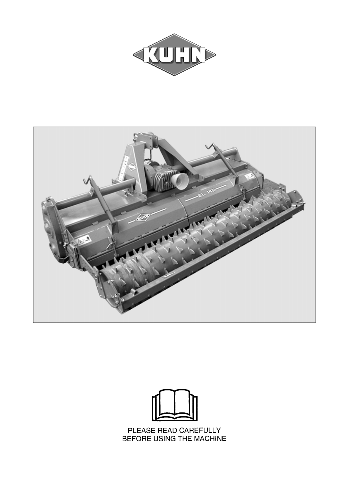
EL 142
POWER TILLER / CULTITILLER / CULTIPLOW
No. 95461CGB A 08.2003
Page 2

DEAR OWNER,
In buying a KUHN machine you have chosen wisely. Into it have gone years of thought,
research and improvements. You will find, as have thousands of owners all over the world, that
you have the best that engineering skill and actual field testing can produce. You have
purchased a dependable machine, but only by proper care and operation can you expect to
receive the performance and long service built into it.
This manual contains all the necessary information for you to receive full efficiency from your
machine. The performance you get from this machine is largely dependant upon how well you
read and understand this manual and apply this knowledge. Please DO NOT ASSUME THAT
YOU KNOW HOW TO OPERATE AND MAINTAIN YOUR MACHINE before reading this
manual carefully. KEEP THIS MANUAL AVAILABLE FOR REFERENCE.
Your KUHN dealer will instruct you on the general operation of your machine. He is interested
that you get the best performance possible and will be glad to answer any special questions
that may arise regarding the operation of the KUHN machine.
Your KUHN dealer can offer a complete line of genuine KUHN service parts.
These parts are manufactured and carefully inspected in the same factory that builds the
machine to assure high quality and accurate fitting of any necessary replacements.
When ordering service parts it is important that you indicate the type of machine concerned
and its serial number.
For this reason please complete the model identification plate diagram below with the required
information. This will provide you with an easy reference for future service parts orders.
ABOUT IMPROVEMENTS
KUHN is continually striving to improve its products and, therefore, reserves the right to make
improvements or changes when it becomes practical to do so, without incurring any
obligations to make changes or additions to the equipment sold previously.
Page 3

TABLE OF CONTENTS
PAGE
Safety 2
Safety Decals - Model identification plate 8
Technical Specifications 10
Guards 12
Fitting to the tractor 1 3
PTO shaft 14
Slip clutch 16
Rotor speeds (rotational frequencies) 17
Adjustment of the rear hood 1 9
Use 20
Equipment 22
1) Rollers 2 2
2) Skids + stand 2 6
3) Gauge wheel kit 2 7
4) Side separating discs 2 8
5) Rear wheel kit 2 9
6) Track eradicators 30
7) Rear hydraulic lift linkage 3 1
8) A-frame kit for VENTA AL and Ti integrated seeder attachment 3 4
9) Semi-automatic hitch 3 4
10 ) Hard coated packer roller scraper plates 3 4
11 ) Nylon cleaning plates for standard packer roller, packer roller
PK2 and maxipacker roller scrapers 3 5
12 ) P.T.O. shafts 3 5
13 ) Rotors complete 35
14 ) Signalling elements 36
Maintenance 37
1) Lubrication 37
2) Fitting blades 3 8
3) Changing the rotor 4 1
Trouble Shooting 42
Conditions of Limited Warranty 45
Copyright 2003 KUHN S.A.
- 1 -
Page 4

SAFETY
The symbol above is used throughout this manual every time recommendations are made concerning your safety,
the safety of others, or the good operation of the machine.
These recommendations must be made known to all machine operators.
DESIGNATED USE OF THE MACHINE
The EL 142 must only be used for the work for which it has been designed :
- Seedbed preparation on ploughed or unploughed ground with or without simultaneous seeding (machine can
be equipped with an integrated or a 3-point mounted seeder).
- Stubble ploughing or reclamation of grassland.
The manufacturer is not held liable for any damage resulting from machine applications other than those specified
by the manufacturer.
Any use other than the designated operation is at the risk and responsibility of the operator.
Designated use of the machine also means :
- following operation, maintenance and repair recommendations given by the manufacturer ;
- using only genuine spare parts, equipment and accessories as designated by the manufacturer.
The EL 142 must only be operated, maintained and repaired by competent persons who are familiar with machine
specifications and operations and are aware of any danger involved.
The operator must imperatively respect current legislation concerning :
- accident prevention,
- work safety,
- public traffic circulation.
All safety advice indicated on the machine must be strictly observed.
The manufacturer is not held liable for any damage resulting from machine modifications carried out by the
operator himself or by a third party without previous written agreement from the manufacturer.
- 2 -
Page 5

GENERAL SAFETY RECOMMENDATIONS
Before operating the machine, always ensure that tractor and machine are in accordance with work safety and
road traffic regulations.
BASIC PRINCIPLES
1. In addition to the recommendations given in this manual, legislation on work safety and accident prevention
must also be respected.
2. Advice is indicated on the machine, specifying safety recommendations in order to prevent accidents.
3. Before travelling on public roads, the operator must ensure that the machine conforms to road traffic
regulations.
4. Before starting work, the operator must be familiar with all machine controls, handling devices and their
functions. Once at work, it is too late to do so !
5. Use a tractor equipped with a safety cab. Keep windows and roof hatch closed for reduced sound level while
operating the PTO driven implement.
6. Before starting up the machine and beginning work, check the surrounding area (beware of children !). Make
sure there is sufficient visibility.
Keep all people and animals away from the danger zone of the machine (risk of projection !)
7. Carrying people or animals on the machine when working or in transport is strictly forbidden.
8. Machine must only be attached to tractor using means provided and in accordance with current safety
standards.
9. Special care should be taken when attaching or removing the machine from the tractor.
10. Before attaching the machine, ensure that the front tractor axle is sufficiently ballasted.
Ballast is to be placed on the supports provided in accordance with instructions of the tractor manufacturer.
11. Do not surpass the maximum axle load or the overall transport weight as prescribed by the tractor
manufacturer.
12. Do not surpass the maximum transport width authorized by road traffic regulations.
13. Before transporting the machine on public roads, ensure that all legally required guards and indicators (lights,
reflectors ...) are in place and in good operation.
14. All operating controls (cords, cables, rods...) must be positioned so that they cannot be set off accidently,
risking accident or damage.
15. Before transporting on public roads, locate the machine into its transport position as instructed in this
operator’s manual.
16. Never leave the tractor seat while the machine is operating.
- 3 -
Page 6

17. Drive speed must be adapted to ground conditions as well as roads and paths.
Always avoid abrupt changes of direction.
18. Precision steering, tractor adherence, road holding and efficient braking are influenced by the type of
implement, weight, ballast of front axle, ground or road conditions. It is therefore of utmost importance to be
cautious in every given situation.
19. Be particularly cautious when turning corners, paying attention to machine overhang, length, height and
weight.
20. Keep clear of the machine operating area.
21. WARNING ! Danger of crushing and shearing can exist when components are operated by hydraulic or
pneumatic controls.
22. Before leaving the tractor or before adjusting, maintaining or repairing the machine, turn off the engine,
remove ignition key and wait until all moving parts have come to a complete stop.
23. Do not stand between the tractor and the machine unless the hand brake is tight and/or stops have been
placed under the wheels.
24. Before any adjustments, maintenance or repairs are carried out, ensure that the machine cannot be started
up accidentally.
PRECAUTIONS TO BE TAKEN BEFORE OPERATING THE MACHINE
1. Do not wear loose clothing which could become caught up in moving elements.
2. Wear the individual protection equipment corresponding to the work which is planned (gloves, shoes, eye
protection, helmet, ear protectors...).
3. All operating controls (cords, cables, rods ...) must be positioned so that they cannot be set off accidentally,
causing accident or damage.
4. Before operating the machine, check the tightness of all nuts and bolts, particularly on rotating parts (blades,
tines, knives, spades ...)
5. Before operating the machine, ensure that all safety guards are firmly in place and in good condition. If worn
or damaged, replace immediately.
ATTACHMENT
1. When attaching or removing the machine from the tractor, position hydraulic lift control lever in such a way that
it cannot be set off accidentally.
2. When attaching the machine to tractor hydraulic linkage, ensure that diameter of link pins corresponds to
diameter of ball joints.
3. WARNING ! Danger of crushing and shearing can exist in the lifting zone of the tractor hydraulic linkage !
4. Do not stand between the tractor and the machine when operating the outer control lever of the lift mechanism.
5. In transport, the machine lift mechanism should be stabilized by tractor tie rods to avoid floatation and side
shifting.
6. When transporting machine ensure that it can not be lowered accidentally.
- 4 -
Page 7

POWER TAKE-OFF
1. Only use PTO shaft supplied with the machine or recommended by the manufacturer.
2. PTO guards must always be in place and in good condition.
3. Check for correct PTO overlap when at work and in transport.
4. Before attaching or removing the PTO shaft, disengage PTO shaft, turn off engine and remove ignition key.
5. If a primary PTO shaft is equipped with a slip clutch or a free wheel, these must be fitted on the machine PTO.
6. Ensure that PTO shaft is always correctly fitted and locked into place.
7. Make sure guards are correctly in place and secured with the safety chains provided.
8. Before engaging PTO, ensure that PTO speed (rotational frequency) and direction are in accordance with
manufacturer's recommendations.
9. Before engaging PTO, keep all people and animals clear from the machine.
10. Never engage PTO shaft when tractor engine is turned off.
11. Never surpass PTO angle recommended by the manufacturer.
12. WARNING ! Rotating elements can continue turning momentarily after PTO is disengaged. Keep clear until
all rotating elements are at a standstill.
13. When removing the machine, locate PTO shaft on the supports provided.
14. Fit safety cap on tractor PTO.
15. Replace any worn or damaged PTO guards immediately.
Rotation speed ... rpm (American Measure) is also expressed in metric measure : Rotational frequency ... min
Both units are equivalent, for example : Rotation speed 540 rpm equals Rotational frequency 540 min-1.
ROAD TRANSPORT
Dimensions
-1
.
Depending upon the machine’s dimensions, the user should check with the relevant authority that it can be
transported legally on public roads.
If maximum authorised size is exceeded, the user should act according to the legislation in force regarding
transport of oversize equipment.
Load per axle and gross weight
When transporting the machine or combined machines, check that :
- the tractor’s authorised gross weight as well as the maximum weight per axle is not exceeded.
- In all circumstances, the weight on the tractor’s front axle is never below 20% of the tractor’s unladen
weight. If the case arises, fit front ballast weights.
- 5 -
Page 8

HYDRAULIC SYSTEM
1. WARNING ! Hydraulic system is under pressure.
2. When fitting hydraulic motors or cylinders, ensure that connections have been made correctly, as per
manufacturer’s instructions.
3. Before connecting hoses to the tractor hydraulics, ensure that tractor and machine circuits are not under
pressure.
4. It is strongly recommended that the operator marks the hydraulic connections between tractor and machine to
avoid making a wrong connection. WARNING ! Functions could be reversed (for example : lift/lower).
5. Check hydraulic hoses regularly ! Worn or damaged hoses must be replaced immediately.
Replacement parts must be in accordance with manufacturer’s recommendations concerning specifications
and quality.
6. Should a leak be found, take all necessary precautions to avoid accidents.
7. Any liquid under pressure (particularly oil from hydraulics) can penetrate the skin and cause severe injury. If
injured, see a doctor immediately, there could be danger of infection.
8. Before any adjustments, maintenance or repairs are carried out, lower the machine, depressurize the circuit,
turn off the engine and remove ignition key.
- 6 -
Page 9

MAINTENANCE
1. Before checking any machine malfunction and before adjusting, maintaining or repairing the machine,
disengage PTO, turn off engine and remove ignition key.
2. Check tightness of nuts and bolts regularly. Retighten if necessary.
3. If the machine is raised, prop it up in a stable position before carrying out any maintenance work.
4. When replacing a working part, wear protection gloves and only use standardized tools.
5. It is forbidden to discard any oil, grease or filters. These must be given to waste disposal organisations to
protect the environment.
6. Disconnect power source before any work is done on the electric system.
7. Check safety guards regularly, particularly those that are subject to wear. Replace immediately if damaged.
8. Spare parts used must be in accordance with specifications and standards as defined by the manufacturer.
Use only genuine KUHN parts !
9. Before any electric welding is carried out on tractor or attached machine, disconnect generator and battery
terminals.
10. Repairs on elements under pressure or tension (springs, accumulators etc...) must only be carried out by
competent persons with standardized equipment.
- 7 -
Page 10
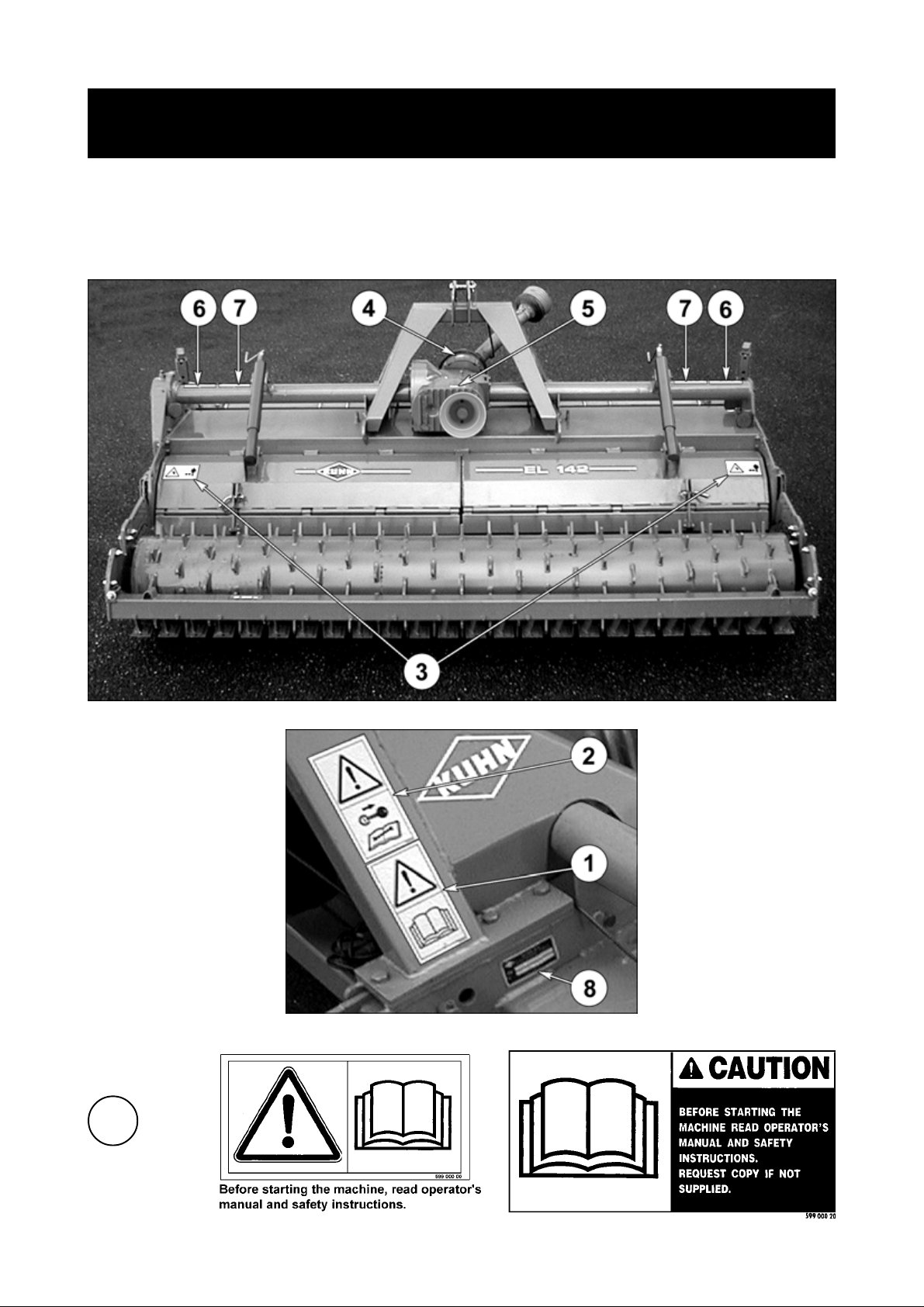
SAFETY DECALS
MODEL IDENTIFICATION PLATE
The following safety pictorials have been placed on your machine in the areas indicated. They
are intented for your personal safety and for the safety of the people working with you. The text
shown on them gives their precise meaning. Keep the pictorials clean. Replace them when they
are faded.
1
- 8 -
Page 11

2
3
4
6
7
5
8
- 9 -
Page 12

TECHNICAL SPECIFICATIONS
SPECIFICATIONS EL 142 EL 142
250 300
Working width m (ft) 2.50 (8’2") 3.00 (9’10")
Maxi. allowable DIN power P.T.O. 750 rpm (min
kW (hp) P.T.O. 1000 rpm (min-1) 103 (140)
Minimum power requirement kW (hp) 66 (90) 73 (100)
Rotor diameter mm (")
- POWER TILLER with standard diameter C-blade rotor 550 (1'9")
- POWER TILLER with larger diameter L-blade rotor 590 (1'11")
- CULTIPLOW rotor with 2 bolts per blade 570 (1'10")
- CULTIPLOW rotor with 1 bolt per blade 570 (1'10")
- CULTITILLER rotor with Fast-Fit blades 570 (1'10")
Number of blades :
POWER TILLER with standard diameter C-blade rotor 60 72
POWER TILLER with larger diameter L-blade rotor 60 72
CULTIPLOW rotor with 2 bolts per blade 84 100
CULTIPLOW rotor with 1 bolt per blade 84 100
CULTITILLER rotor with Fast-Fit blades 56 66
Working depth adjustable min. / max. mm (") 8 (1/3") / 25 (1")
Working depth control with skids, gauge wheels or roller
Attachment cat. 2 and 3N
Overall machine transport width cm (ft) 277 (9'1") 325 (10'8")
Overall machine working width (with safety guards) cm (ft) 293 (9'7") 341 (11'2")
-1
) 77 (105)
*
* Optional equipment (see page 13).
- 10 -
Page 13

SPECIFICATIONS EL 142 EL 142
250 300
Weight with packer roller : (kg / lbs)
- POWER TILLER with standard diameter C-blade rotor 1400 (3080) 1560 (3432)
- POWER TILLER with larger diameter L-blade rotor 1450 (3190) 1615 (3553)
- CULTIPLOW rotor with 2 bolts per blade 1510 (3322) 1675 (3685)
- CULTIPLOW rotor with 1 bolt per blade 1495 (3289) 1665 (3663)
- CULTITILLER rotor with Fast-Fit blades 1405 (3091) 1565 (3443)
Weight with packer roller PK2 : (kg / lbs)
- POWER TILLER with standard diameter C-blade rotor - 1595 (3509)
- POWER TILLER with larger diameter L-blade rotor - 1650 (3630)
- CULTIPLOW rotor with 2 bolts per blade - 1710 (3762)
- CULTIPLOW rotor with 1 bolt per blade - 1700 (3740)
- CULTITILLER rotor with Fast-Fit blades - 1600 (3520)
Weight with maxipacker roller : (kg / lbs)
- POWER TILLER with standard diameter C-blade rotor 1455 (3201) 1625 (3575)
- POWER TILLER with larger diameter L-blade rotor 1505 (3311) 1680 (3696)
- CULTIPLOW rotor with 2 bolts per blade 1565 (3443) 1740 (3828)
- CULTIPLOW rotor with 1 bolt per blade 1550 (3410) 1730 (3806)
- CULTITILLER rotor with Fast-Fit blades 1460 (3212) 1630 (3586)
Weight with crumbler roller : (kg / lbs)
- POWER TILLER with standard diameter C-blade rotor 1260 (2772) 1390 (3058)
- POWER TILLER with larger diameter L-blade rotor 1310 (2882) 1445 (3179)
- CULTIPLOW rotor with 2 bolts per blade 1370 (3014) 1505 (3311)
- CULTIPLOW rotor with 1 bolt per blade 1355 (2981) 1495 (3289)
- CULTITILLER rotor with Fast-Fit blades 1265 (2783) 1395 (3069)
Weight with maxicrumbler roller : (kg / lbs)
- POWER TILLER with standard diameter C-blade rotor 1270 (2794) 1400 (3080)
- POWER TILLER with larger diameter L-blade rotor 1320 (2904) 1455 (3201)
- CULTIPLOW rotor with 2 bolts per blade 1380 (3036) 1515 (3333)
- CULTIPLOW rotor with 1 bolt per blade 1365 (3003) 1505 (3311)
- CULTITILLER rotor with Fast-Fit blades 1275 (2805) 1405 (3091)
Weight with skids : (kg / lbs)
- POWER TILLER with standard diameter C-blade rotor 1075 (2365) 1200 (2640)
- POWER TILLER with larger diameter L-blade rotor 1125 (2475) 1255 (2761)
- CULTIPLOW rotor with 2 bolts per blade 1185 (2607) 1315 (2893)
- CULTIPLOW rotor with 1 bolt per blade 1170 (2574) 1305 (2871)
- CULTITILLER rotor with Fast-Fit blades 1080 (2376) 1205 (2651)
Weight with gauge wheels : (kg / lbs)
- POWER TILLER with standard diameter C-blade rotor 1095 (2409) 1225 (2695)
- POWER TILLER with larger diameter L-blade rotor 1145 (2519) 1280 (2816)
- CULTIPLOW rotor with 2 bolts per blade 1205 (2651) 1340 (2948)
- CULTIPLOW rotor with 1 bolt per blade 1190 (2618) 1330 (2926)
- CULTITILLER rotor with Fast-Fit blades 1100 (2420) 1230 (2706)
- 11 -
Page 14
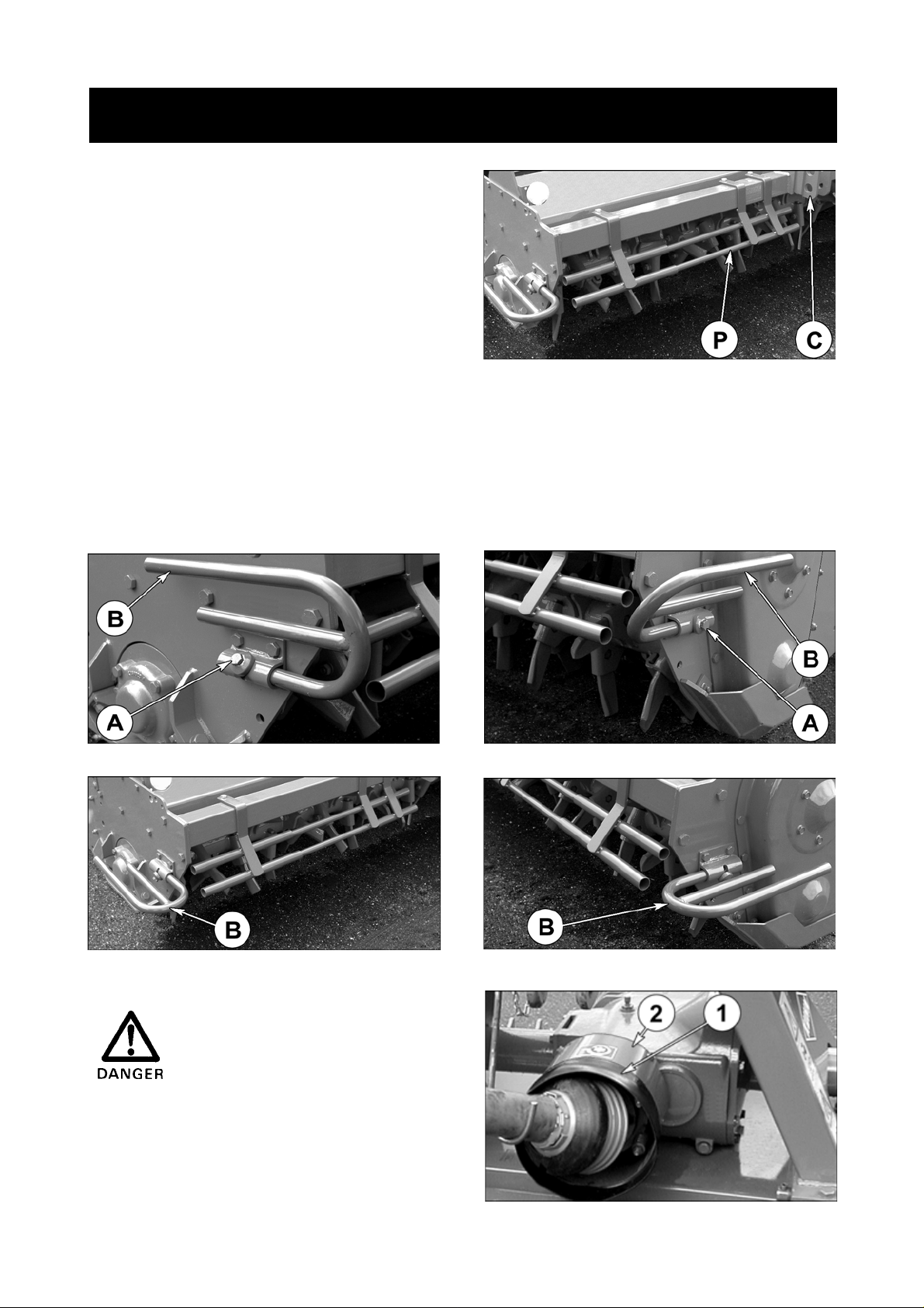
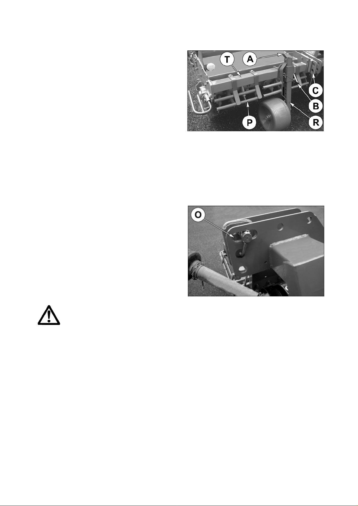
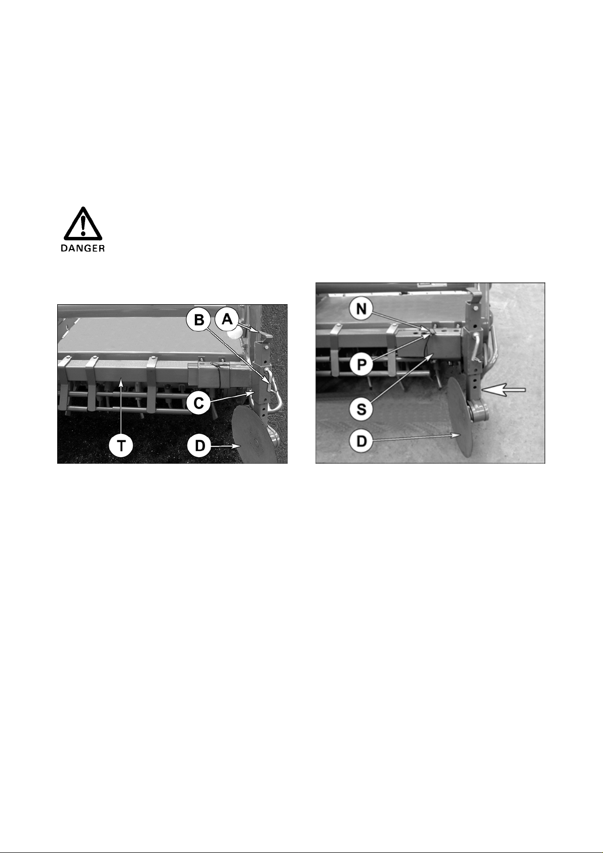
GUARDS
1) Front safety guards
The safety guards increase the safety of the machine.
The 2 front safety guards (P) are made up of 3 parts,
one fixed and 2 sliding sections. They are factory
fitted as shown on photo 1.
The sliding sections of the safety guards may need to
be repositioned (front wheels, track eradicators…).
Whatever the accessories the machine is equipped
with, the guards must remain fixed and cover the
whole length of the machine from the outside of the
adjustable lower link brackets (C) (photo 1).
2) Side safety guards
To reduce the machine width for road transport, proceed as follows :
- loosen the screws (A) of guards (B) (photos 2 and 3)
- pivot guards (B) upwards (photos 2 and 3),
- tighten screws (A).
1
2
4
Side guards (B) are safety
elements, they must be always
folded downwards at work (photos 4 and 5).
3) Guard extension
Fit the guard extension (1) over the sheet metal guard
(2) of the torque limiter (see photo 6).
3
5
- 12 -
6
Page 15
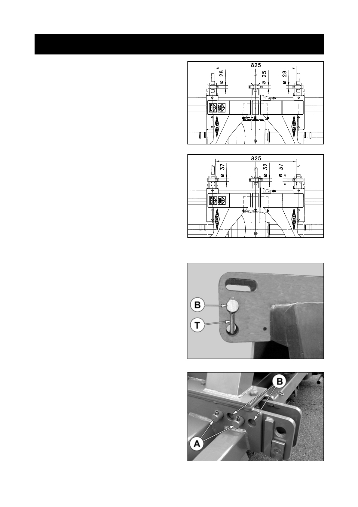
FITTING TO THE TRACTOR
The EL 142 can be fitted to all tractors equipped with
a standard Cat. 2 or Cat. 3 three-point hitch (figure 7).
Category "2"
- original equipment
Alternative attachment :
Category “ 3 N ”
(with a cat.2 space between lower lift arms)
Recommended with a EL 142/seed drill combination.
The top hitch pin (code 525 970 00) and the lower hitch
pins cat.3 (code 525 925 00) are available through the
Kuhn Service Parts Department.
7
Note : The top link pin (B) has an anti-turn arm (T). It
should be fitted as shown in photo 8.
The lower attachment yokes can be placed in 2
different positions on the main frame.
1) Towards the rear (A) (photo 9) (original fitting) : to
bring the centre of gravity of the machine as close to
the tractor as possible (in combination with a seed
drill for example).
7A
8
2) Towards the front (B) (photo 9) : to avoid any
clashing with the tractor wheels when fitting certain
equipments such as front gauge wheels or track
eradicators.
9
- 13 -
Page 16
P.T.O. DRIVE SHAFT
10
Make sure the EL 142 is resting on the ground and is maintained in a stable position. Clean and lubricate the
gearbox input shaft and slide the mating PTO shaft yoke in place. Before attaching the PTO shaft to the slip clutch
flange, it is essential that both mating surfaces are thoroughly cleaned.
Bring both components together and fix in place using the self-locking screws provided. Tighten all the studs to
a torque setting of 10 daNm (75 ft.lbs) at the same time making sure that the flange is centrally seated.Tightness
has to be checked regularly.
After mounting the EL 142, stabilize the tractor 3-point linkage with whatever means are recommended i.e. the
bars, chains, etc.
Be sure the tractor P.T.O. shaft drive is disengaged and stop engine.
Couple the P.T.O. shaft to the tractor P.T.O stub.
Attachment is correct when machine is horizontal in work position.
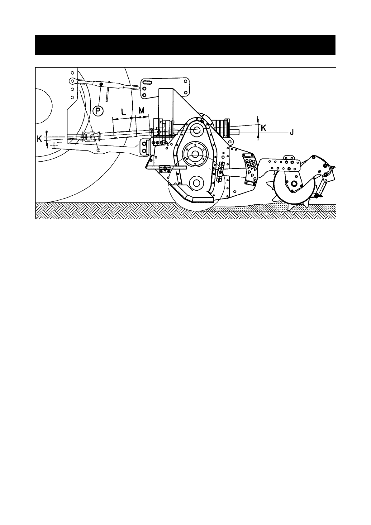
With the machine resting on the ground, adjust the top link (P) length to a position where the tractor PTO stub and
the tiller input shaft are parallel.
In working position :
- The 2 angles (K) formed by the centre lines of the yoke and the sliding tubes must be equal and not exceed a
combined angle of 30° when working.
- The sliding tube overlap (L) must be at least 22 cm (8.5") (fig. 10).
With the machine fully raised on the tractor hydraulic linkage :
- The 2 sliding tubes must not completely overlap each other ; a gap (M) of 1 cm (3/8") should exist between end
of sliding tube and yoke.
- Both U joints (K) should operate approximately at the same bent angles which must never exceed 40°
(fig. 10).
Should the above mentioned conditions not exist :
- Shorten both tubes by an equal length (fig. A and B), chamfer edges (fig. C) and grease liberally (fig. D) before
refitting.
- To avoid noisy running of the PTO shaft when lifting the machine out of work, attach top link (P) so that it is almost
parallel to the lower links (fig. 10).
Important : Always disconnect the tractor PTO drive before lifting the machine into the transport position,
otherwise permanent damage can be caused to the transmission shaft.
Repeat these adjustments each time the machine is mounted to a different tractor.
- 14 -
Page 17

A
B
C
A hook (C) is supplied with the machine to support
the PTO shaft (T) when disconnected to avoid
damage or deterioration due to contact with the
ground (photo 11).
To avoid accidents which could be serious, make sure that the guards are always
correctly in place and secured with the safety chains. On the machine side, attach
restraining chain (H) to the corresponding hole on the right side of the hitch frame (photo
11). All worn or damaged guards must be replaced immediately.
D
11
- 15 -
Page 18
FRICTION SLIP CLUTCH
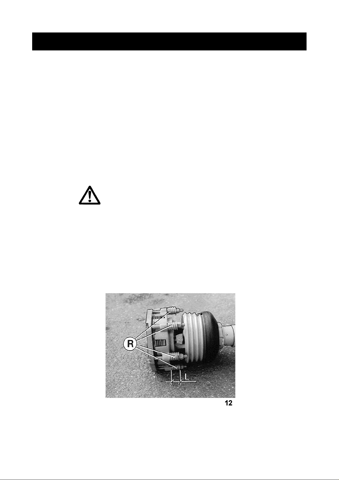
The EL 142 is factory equipped with an adjustable friction slip clutch.
Spring pressure is factory pre-set (L = 32 mm / 1 1/4") for 103 kW (140 hp) tractors at 1000 rpm (min-1) PTO (photo
12).
The theoretical average length of springs (R) (L = 32 mm / 1 1/4") is only an indication and can be slightly modified
according to machine width, work conditions and tractor. Too light a spring pressure will allow the plates to slip
continuously or intermittently at frequent intervals, resulting in overheating and rapid wear of the friction plates.
On the other hand, over pressured or completely coil bound springs will provide no protection to the drive
components (this occurs at 31 mm spring length).
IMPORTANT : * Always check if the clutch is set correctly for the work to be carried out. It should feel warm
to the touch during work.
* If the clutch slips excessively (too light a spring pressure, obstacles, etc.), readjust if
necessary and wait until the temperature of the clutch drops to a normal work temperature of
approximately 40°C (104 °F) before getting back to work. If the clutch overheats it will slip more
easily, thus increasing disc wear.
* With L = 31 mm the springs (R) will be completely coil bound and the clutch cannot operate.
Never work with springs fully locked as this risks deteriorating drive line components if an
obstruction jams the rotor. Always loosen at least half a turn.
NEVER FULLY LOCK THE SPRINGS.
Check clutch setting regularly, especially after the machine hasn’t worked for a long time. Completely slacken
off the 6 springs (R) by unscrewing their securing nuts, let the friction plates slip for a few seconds then retighten
springs as explained above (to L = 32 mm / 1 1/4").
Note : We recommend that the clutch guard be removed for easier access when carrying out slip clutch
adjustments. Don’t forget to bolt guard back in place after adjustments have been made.
- 16 -
Page 19

ROTOR SPEED (ROTATIONAL FREQUENCY)
The EL 142 is fitted with a speed gearbox which adapt the rotor speed (rotational frequency) to the working
conditions.
To change the PTO speed (rotational frequency) invert or replace the sets of matching gearwheels located at the
rear of the gearbox. The machine is standard equipped with 2 sets of gearwheels.
To invert the pinions proceed as follows. Tilt the machine forward to avoid oil leaking out of the gearbox when
removing the cover.
To do this :
- uncouple the PTO shaft
- shorten the turn buckle
- raise the machine in order to obtain a satisfactory angle
- remove bolts (U) from cover plate (V) and pull the cover and gearwheel assembly out of the gearbox (photo 13),
- invert the set of matching gears (A and B) or replace it by the set (C and D), according to the desired rotor speed
(rotational frequency) (photo 14),
- always store the non used set of matching gears inside the gearbox by placing gearwheel (D) on the rear PTO
shaft and gearwheel (C) on the cover plate (photo 14),
- reinstall the cover plate making sure to position the O-ring (E) in its groove correctly (photo 14).
13
Rotor speed (rotational frequency) chart EL 142 in rpm (min-1) :
P.T.O.
speed
(rotational
frequency)
750 rpm (min-1) 183 214 - 273
1000 rpm (min-1) 244 286 191 364
* Ex-Works setting
Position of
gears
*
26 24 24 26 29 21 21 29
1st gear set
Recommended PTO speed (rotational frequency)
14
2nd gear set
- 17 -
Page 20

The gearbox is factory fitted with a rear PTO shaft (S) which rotates at the same speed (rotational frequency) as
the tractor PTO shaft (photo 16). An extra implement can be driven by a secondary PTO shaft which should be
assembled and used according to the legislation in force at the time.
Remove the PTO shaft cover (O) (photos 15 and 16). The rear PTO shaft is 1 3/8" 6 spline profile, and must not
be used to transmit more than 37 kW (50 hp).
If the rear PTO shaft is not used, always put cover (O) in place (photo 15).
15
16
- 18 -
Page 21

ADJUSTMENT OF THE REAR HOOD
The rear hood unit consists of:
- Hood (Q) the position of which can be adjusted by
cranked handles (P) (photo 17)
- Flap (R) which can be adjusted and locked by
inserting pins (B) into holes (S) (photos 18 and 19)
The desired tilth can be obtained by adjusting the
position of rear hood (Q):
- lowering the hood increases the working of the
ground (see arrow C, figure 20) giving a finer tilth
- raising the hood reduces the working of the ground
giving a coarser tilth (figure 21).
17
18
Flap (R) must always be set to ensure that it levels the ground according to the flow of soil behind the rotor (figures
20 and 21). In order to keep the machine stable it is essential that the ground is well levelled in front of the roller.
If the flap is not correctly adjusted the ground surface will be undulating which can result in the machine pitching
or rolling in work, especially when travelling fast.
19
20 21
- 19 -
Page 22

USE
Before carrying out any operation on the machine, stop the tractor engine,
remove ignition key and wait for all rotating parts to stop before leaving the tractor.
Clod size should be different depending on the job to be done.
The following features determine clod size :
- Choice of rotor (either POWER TILLLER, CULTITILLER or CULTIPLOW)
- Rotor speed (rotational frequency)
- Working depth
- Hood position.
- Position of the flap.
- Forward speed.
- Number of passes.
The rear hood/flap unit must be set to ensure that there is no risk of it touching the roller
during work.
To obtain fine clods :
- High rotor speed (rotational frequency)
- Hood (Q) lowered (figure 20, page 19)
- Set the position of flap (R) in relation to the working depth to ensure that it performs its function of levelling (figure
20, page 19)
- Low forward speed
- Choice of the rotor in accordance with given work conditions :
. CULTITILLER rotor with angled blades
. CULTIPLOW rotor with curved blades : a greater shattering effect to get even finer clods.
. POWER TILLER rotor with "three pairs of blades per flange".
To obtain coarser clods :
- Low rotor speed (rotational frequency)
- Hood (Q) raised (figure 21, page 19)
- Set the position of flap (R) in relation to the working depth to ensure that it performs its function of levelling (figure
21, page 19)
- Higher forward speed
- Choice of the rotor in accordance with given work conditions (CULTITILLER, CULTIPLOW or POWER TILLER
with "2 pairs of blades per flange").
EL 142 CULTITILLER or CULTIPLOW
With the EL 142 CULTITILLER or CULTIPLOW, clods are shattered vertically without modifying their natural
structure : not too many clods, nor too much fine soil !
Points are spirally mounted, working and aerating the ground over the entire rotor width ; no panning. They engage
into the ground with a digging action without risk of gathering up vegetable residue. The angle at which the blades
of the CULTITILLER rotor enter the ground has the effect of a pickaxe. The “trailing” position of the blades in
CULTIPLOW version eliminates nearly all risks of clogging and building up of plant residues.
The roller controls working depth and levels and packs the seedbed behind the machine.
The EL 142 CULTITILLER or CULTIPLOW is a very versatile machine offering a wide range of applications :
- turning in stubble
- soil preparation after ploughing
- and in some cases, direct soil preparation without ploughing.
- 20 -
Page 23

EL 142 POWER TILLER
The POWER TILLER rotor fitted with mulch blades "BH" is world renown for its excellent incorporation of organic
matter into the ground.
The POWER TILLER rotor can be equipped with either 2 or 3 spades, depending on the soil profile required. When
it comes to turning in stubble and reclaiming old pastures, the Power Tiller rotor is at it’s best.
The Power Tiller rotor fitted with mulch blades "BH" is recommended for :
- turning in green manure, dung, harvest residues
- reclaiming old pastures
- orchard maintenance
- turning in stubble
- market gardening.
Note : Before working in vegetable residue, an independant shredder must be used first to obtain a fine
shred and even distribution of residue so that it can then be easily incorporated into the ground, getting
a good mix. The more residue there is, the more important this is.
Hints on use :
- Allow the rotor to rotate at ist working speed before engaging it into the soil. Gradually lower the machine while
pulling forward with the tractor.
- Always work in a straight line. When turning, lift machine out of work.
- Never work in reverse, otherwise damage could occur to some component parts.
- Do not disengage the PTO drive unless the machine has been lifted out of work.
Important remarks :
Like many farm machines, use of the EL 142 entails limits which must be respected in all situations. These limits
are often tied in with :
- meteorological conditions : avoid working during and immediately after rainfall, wait until ground to be worked
is completely drained,
- soil types : smooth clods indicate too malleable or too humid soil to be worked in. Wait until ground is completely
drained. Soil consistency is ideal when clods crumble without sticking,
- tractor power : adapt working depth, forward speed and rotor speed (rotational frequency) to power available
and type of work to be done. Never exceed the maximum allowable tractor DIN power : 103 kW (140 hp).
- hood adjustment : The machine should not be operated with the hood (Q) (photo 17, page 19) completely
closed. The hood should always be sufficiently open so that worked ground can flow out freely. If the rotor is
operating deep down in the soil and the hood is closed, the large amount of worked ground could clog the rotor
and deteriorate the hoods.
- 21 -
Page 24

EQUIPMENT
1) ROLLERS
The operator may choose to equip the EL 142 with :
- either a packer roller (studs welded onto a cylinder),
- either a packer roller PK2 (studs welded onto a cylinder) (only for EL 142 - 3,00 m),
- either a maxipacker roller (rows of discontinuous studs welded on a large diameter cylinder),
- either a crumbler roller (welded tubes and removable bars)
- or a maxicrumbler roller (welded tubes).
The roller :
- adjusts and controls rotor working depth
- packs the ground behind the rotor to create an ideal seedbed
- increases crumbling efficiency by breaking down the clods
- improves ground levelling.
Adjusting the roller (photo 23)
Adjustment in direction of travel :
The roller can be placed in six different horizontal
positions so that the overhang is reduced to a minimum in relation to the hood. This shift is carried out
with the 3 screws (C) on the multi-hole arms (A) and
plates (B) (photo 23).
23
Height adjustment :
The roller height is adjusted at (P) (photo 23).
To adjust, proceed as follows:
- Lift the machine behind the tractor,
- Place pin (T) in the hole corresponding to the required height (photo 23). Make sure that the same hole is used
on each side of the machine.
To limit the roller downward movement when manoeuvring on field end, a 2nd pin (T) may be ordered under part
number 517 070 00 (2 x) and be inserted in holes (O) of the adjustment plate (P) (photo 23). Do not restrain the
roller movement if the machine is equipped with a Venta seed drill resting on the roller arms.
To raise the roller completely out of work, lift the roller, then place the original pins (T) in holes (O).
Fitting of the adjustment sectors and roller arm mounting brackets (photo 23)
Fit the adjustment sectors (P) on the side plates using 8 cup square bolts (I) (M12 x35) and 8 self-locking nuts (M
12) (screw heads positioned on the inner side of the side plates).
Fit the roller arm mounting brackets (K) on the side plates using 4 hexagonal screws (M) (M 12x35) and 4 selflocking nuts (M 12).
- 22 -
Page 25

A) STANDARD PACKER ROLLER AND PACKER ROLLER PK2 :
- EL 142 - 2.50 m : Kit No.121 6650 (standard)
- EL 142 - 3.00 m : Kit No.121 6600 (standard), Kit No. 121 7080 (PK2)
This rollers are particularly intended for use in wet or sticky soils. Efficient packing, proper levelling and good
crumbling are always achieved. Mud scrapers are an integral part of the standard packer roller and of the packer
roller PK2. These scrapers, placed between the rows of studs, ensure that the roller is cleaned.
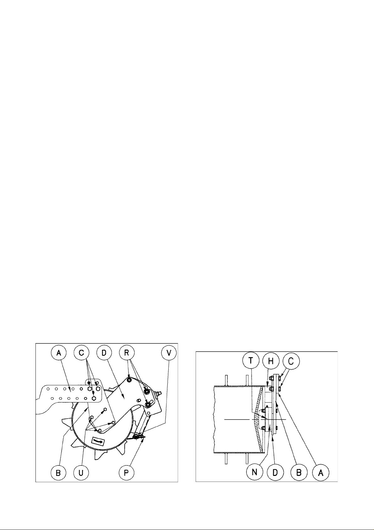
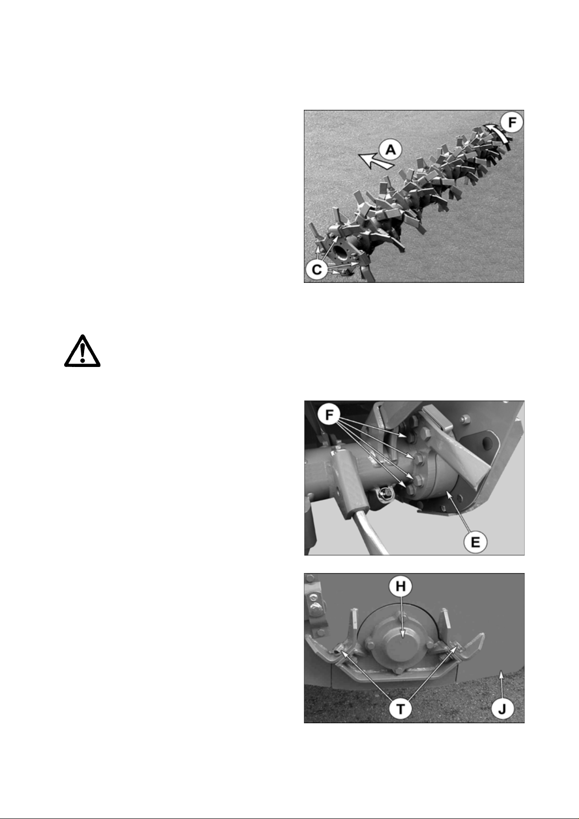
a) Assembly of the packer rollers and their scrapers
When assembling the roller, take particular care concerning the direction of rotation. The direction of rotation is
indicated on the decal affixed to the side of the roller (see arrow, figure 24).
Using 8 bolts (U) and M 12 nuts and mount roller arms (B) and scraper bar arms (D) on the bearing housings (T)
placing spacer (N) as shown on drawings 24 and 25 (torque 10 daNm / 74 ft.lbs).
Then fit the swinging arms (A) on roller arms (B) with 6 bolts (C) and M16 nuts using the 3 holes (C) (torque 22
daNm / 160 ft.lbs) (fig. 26).
Then bolt the scraper bar (H) onto holders (D) using the 4 screws (R) (figure 24). Do not fully tighten these bolts
at this stage. Check that all the cleaners (P) of the scraper are in the retracted position.
Position the 2 eybolts (Q) (photo 27). Using the two nuts (S) tighten against the tensioners to pivot the scraper
towards the roller until the two elongated holes almost butt out (photo 27). Thereafter tighten the four bolts (R) and
adjust the scraper plates (P) as described below (torque 22 daNm / 160 ft.lbs).
Then mount the complete roller assembly with arms (A) on the roller arm brackets (K) by means of 2 pins (X)
secured with 2 self-locking screws (J) (M10 x 16) (photo 23, page 22).
24
26
25
27
- 23 -
Page 26
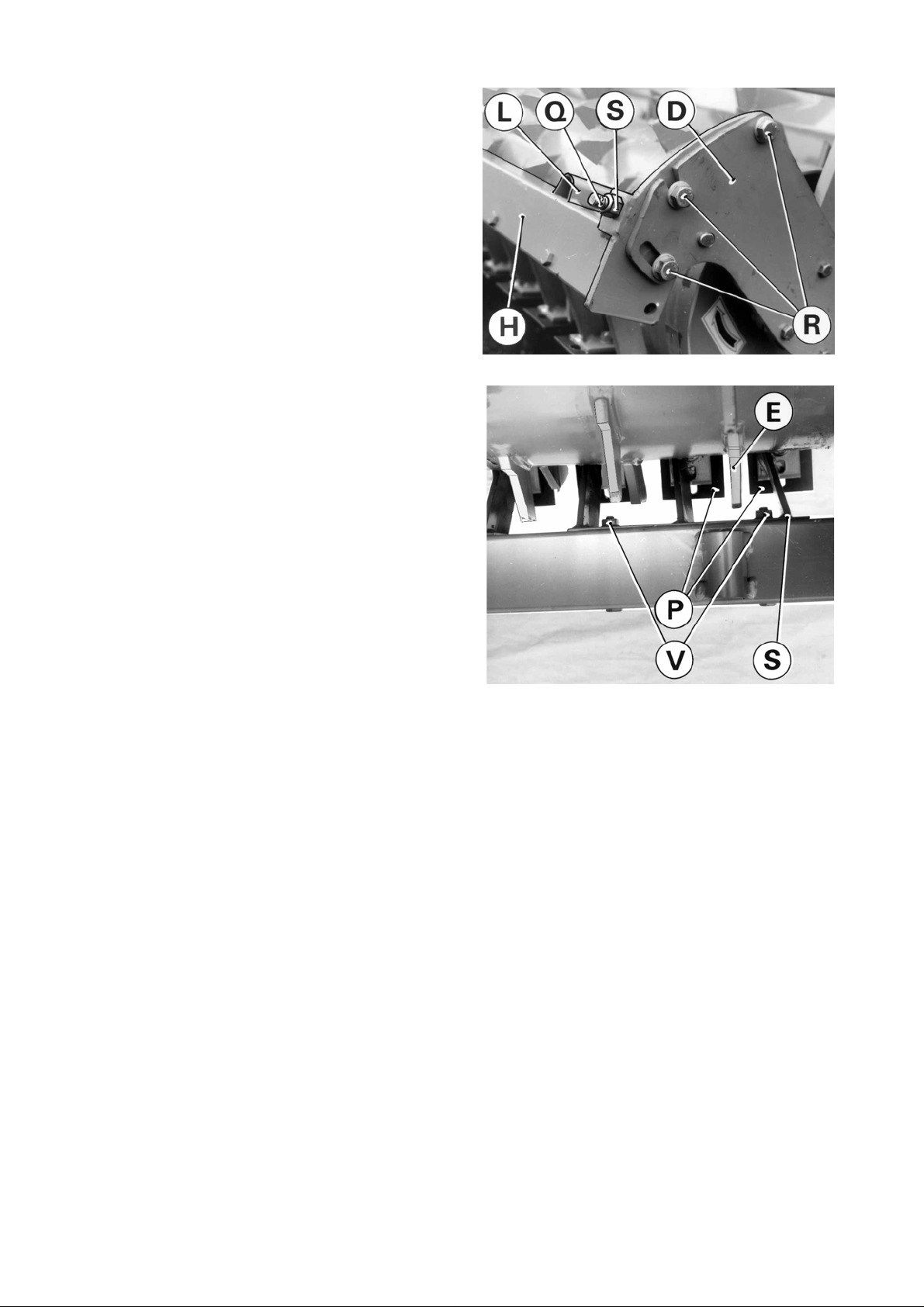
b) Adjusting scraper plates
- Slightly loosen fixing bolts (V) of the scrapers (P) so that they slide freely (figure 24, page 23).
- Check that their position is central relative to the rows of roller teeth. The scraper supports have elongated holes
to allow readjustment if necessary.
- After having checked that the scraper bar is in its furthest forward position (photo 27, page 23), position scraper
plates one at a time so that they are all in contact with the roller. Retighten bolts (V) to 8 daNm / 50 ft.lbs (figure
24, page 23). Make sure that the plates only lightly touch the roller and do not interfere with its rotation.
c) Cleaning the scrapers
In case of crop or soil build-up, to clean, it is recommended that the scraper assembly be pivoted to the rear around
the two upper bolts (R) (photo 27, page 23).
- Loosen the self-locking nuts (S) (photo 27, page 23).
- Release the two eyebolts (Q).
- Remove the two lower bolts (R) (photo 27, page 23).
- To facilitate pivoting the scraper assembly, use a lever in each of the two holes (L) situated at each end of the
connecting tube (H) (photo 27, page 23).
B) MAXIPACKER ROLLER 2,50 m - Kit No. 121 6690
3,00 m - Kit No. 121 6700
This roller is suitable for all soil types and especially humid and sticky soils. It provides an efficient ground packing,
a good levelling and crumbling.
Due to its large diameter cylinder, it provides a large ground contact area, hence reduced sinking and less
resistance to rolling, meaning a reduced traction power is needed. The scraperbar is part of the maxipacker roller.
The scraper plates located between the rows of studs ensure the cleaning of the roller. They are hard coated to
further increase their service life.
In case of blocking with crop residues, the scraper bar can be easily pivoted to permit cleaning.
a) Fitting the maxipacker roller and its scraper (figures 28 and 29 and photo 30).
When fitting the roller, be sure to check its direction of rotation. The direction of rotation is indicated by a sticker
on the side of the roller (see arrow on figure 28).
Using 8 bolts (U) and M12 nuts and mount roller arms (B) and scraper bar arms (D) on the bearing housings (T)
placing spacer (N) as shown on drawings 24 and 25 (torque 10 daNm / 74 ft.lbs).
Then fit the swinging arms (A) on roller arms (B) with 6 bolts (C) and M16 nuts using the 3 holes (C) (torque 22
daNm / 160 ft.lbs) (fig. 26, page 23).
Then fit scraper supporting bar (H) onto the 2 support arms (D) with the 6 bolts (R). Do not tighten the bolts at this
stage (figure 28).
28
29
- 24 -
Page 27
Fit the 2 adjusters (Q) (photo 30). Using the 2 nuts (S)
on the adjusters, bring the scraper bar towards the
roller until it is almost bottomed-out in the 2 slots of the
support arms (D) (photo 30). Then tighten the 6 bolts
(R) to a torque of 22 daNm / 160 ft.lbs, and if required
adjust the position of the scraper plates (P) as shown
thereafter.
Then mount the complete roller assembly with arms
(A) on the roller arm brackets (K) by means of 2 pins
(X) secured with 2 self-locking screws (J) (M10 x 16)
(photo 23, page 22).
b) Adjusting the scraper plates
- The hard coated thick scraper plates have been factory
pre-set on a reference roller. Therefore, they are nearly
in the correct working position after mounting the scraper
bar (paragraph a, page 24).
- If necessary, adjust the scraper plates so that they are in
contact with the roller and tighten the screws (torque 8
daNm / 50 ft.lbs). Make sure that the scraper plates
only lightly touch the roller and do not interfere with
its rotation.
- Also make sure that the scraper plates (P) are well
centred with regards to the stud rows (E) (photo 31). The
scraper plate supports (S) are equipped with oblong
holes enabling to recentre them by sliding them crosswise at the screw level (V) (torque 10 daNm / 74 ft.lbs).
30
c) Cleaning the scrapers
In case of crop residue build-up, it is recommended for cleaning that the scraper be pivoted backwards around
the 2 upper bolt holes (R) (figure 28, page 24). To do this, untighten the 4 lower bolts (R) and release the 2 adjusters
(Q) after loosening their self-locking nuts (S) (photo 30).
To ease pivoting of the scraper bar towards the rear, use a lever in holes (L) (photo 30) placed at each side of the
scraper bar (H).
31
C) CRUMBLER ROLLER : 2,50 m - Kit No. 121 6670
3,00 m - Kit No. 121 6680
The crumbler roller is ideal for dry and slightly humid conditions. It is made up of fixed welded tubes (F) and
removable bars (G), held in place by round support rings (figure 32, page 26).
With removable bars in place :
Recommended in dry conditions for fine tillage and levelling with good ground packing.
Without removable bars in place :
Recommended in more humid ground, less risk of roller clogging. Tillage and levelling are coarser.
Bars can be removed as follows :
- Remove inside roll pins
- loosen the bars using a hammer
- pull out the bars.
- 25 -
Page 28

Using 8 bolts (U) and M12 nuts, mount the roller arms (B) together with the covers (D) on the roller bearing housings
(T) placing a spacer (N) as shown on drawings 32 and 33 (torque 10 daNm / 74 ft.lbs). Then fit the swinging arms
(A) on roller arms (B) with 6 bolts (C) and M16 nuts using the 3 holes (C) (torque 22 daNm / 160 ft.lbs) (fig. 26,
page 23).
Then mount the complete roller assembly with arms (A) on the roller arm brackets (K) by means of 2 pins (X)
secured with 2 self-locking screws (J) (M10 x 16) (photo 23, page 22).
32
D) MAXICRUMBLER ROLLER (photo 34)
2.50 m - Kit no. 121 6950
3.00 m - Kit no. 121 6870
The maxicrumbler roller is ideal for dry or slightly
humid conditions. It is not advisable to use it in
conjunction with an integrated seed drill.
It is made up of fixed tubes (F) welded on round
support rings (photo 34).
2) SKIDS + STAND (photos 35 and 35 A)
Kit no 120 9210
The EL 142 can be equipped with 2 skids which must be mounted on each side of the machine.
This equipment is recommended in Cultirotor version when no roller for working depth control is fitted.
Depth control is adjusted by means of 6 hole skid bars (T) (photo 35).
Assemble skids following photo 34. First remove the wear plate of the lateral housing.
A stand (E) is supplied with the skids to ensure stability when machine is parked (photo 35 A).
33
34
35
35A
- 26 -
Page 29
3)FRONT GAUGE WHEELS
(photo 36)
The EL 142 can be equipped with a gauge wheel kit.
Wheels (R) are fitted on cross tube (T) in front of the
machine. This equipment is recommended either in
Cultirotor version when no roller is fitted, or for all
versions combined with a roller in order to improve the
machine’s stability.
Wheels (R) can easily be adjusted in height inside
their supports using pins (B).
Handles (A) make it easier to handle the gauge
wheels (R).
Kit no 121 6640
36
NOTE : - When mounting the front wheels, slide guards (P) (photo 36) so that they cover the complete
front part of the machine located at the exterior of the 3-point frame’s mounting yokes (C). The
gap between guards (P) and the wheels columns (R) must be of less than 60 mm.
- In addition, on 230 and 250 models, dismount the front safety guard inner part on each side
of the headstock in order to obtain the space required to fit the front gauge wheels.
IMPORTANT NOTE CONCERNING THE USE OF
FRONT GAUGE WHEELS
When the EL 142 is used with front gauge wheels
combined with a roller, the tractor top link must be
connected to the oblong hole (O) on the machine’s 3point frame (photo 37). With this method of hitching
the machine adapts freely to the ground contours,
independently of the tractor.
Coupling the top link to the oblong hole (O) on the machines headstock is only intended for
work. It is strictly forbidden to use this hole during transportation.
37
- 27 -
Page 30
4) SIDE SEPARATING DISCS (photos 38 and 38A)
Kit no. 121 6630
These discs improve soil movement towards the rotor and thus achieve a better definition between worked and
unworked land. The side separating discs also help to stabilize the machine during surface work. Fit the side
separating discs (D) to the cross bar (T) as shown in photo 38. They are adjustable in height on the inside of their
supports (C) using pins (B).
They are also adjustable laterally. Make sure to set both side discs (D) in the same position.
Handles (A) make it easier to handle the side separating discs (D) and also act as a stop to prevent accidents.
At transport, in order to reduce the overall width, the side separating discs (D) must be
completely retracted into their supports (S) (see arrow) and locked in the holes (N) using the
pins (P) (photo 38A).
38
38A
- 28 -
Page 31
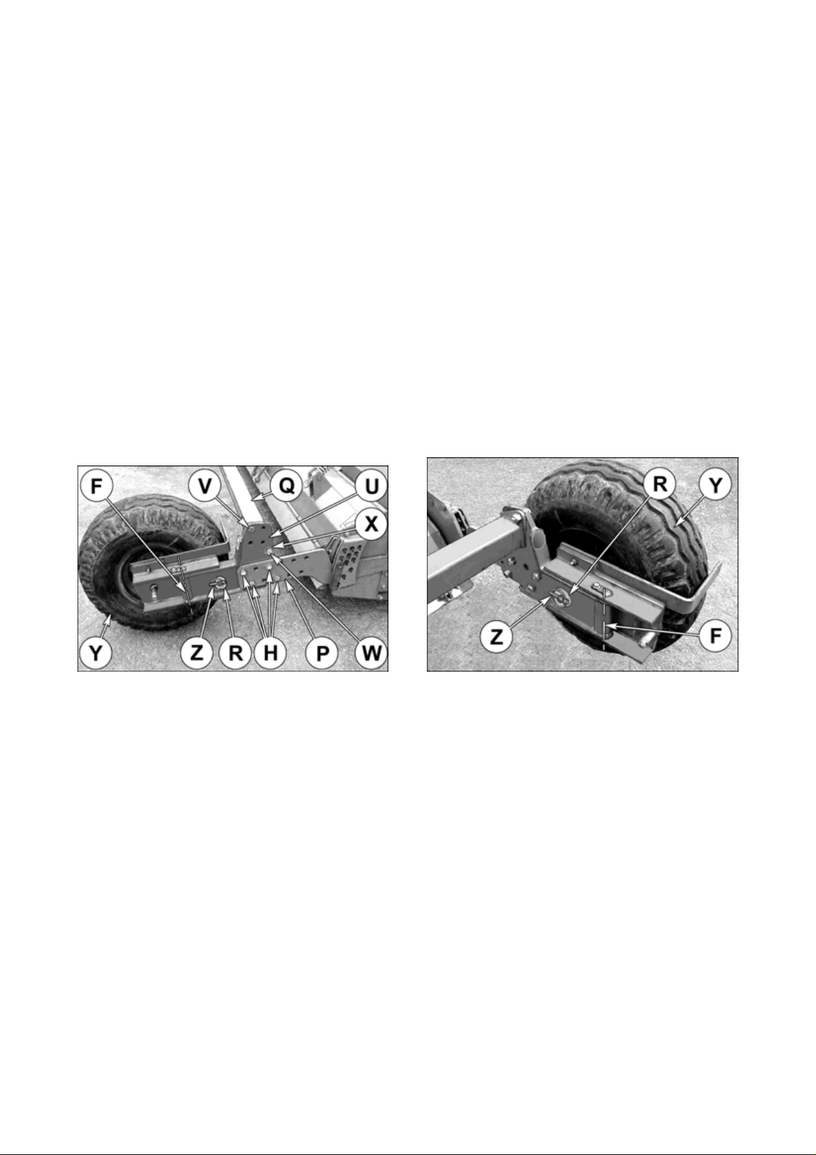
5) REAR WHEEL KIT (photos 39 and 40)
Kit no. 121 6360 for EL 142 - 2.50 m
Kit no. 121 6370 for EL 142 - 3.00 m
Rear wheels can be fitted in place of the roller for certain surface operations (for example, stubble clearing or
turning over pastures).
The rear wheel kit can be fitted in various positions (lengthways) on the roller arms (P) delivered with the kit by
means of 8 hexagon bolts (H) (M 16 x 55) and 8 self-locking nuts (M 16).
Next fit cross bar (Q) on the fixed arms (U) of the rear wheels using 2 hexagon bolts (V) (M 16 x 55), 2 hexagon
bolts (W) (M 16 x 55), 2 flat washers (X) (diameter 16 x 30 x 3) and 4 self-locking nuts (M 16). The cross bar can
be fitted either in the upper position (as shown on photos 39 and 40) or the lower position (when working with an
integrated seeder or separate seeding system). When fitting in the lower position use the 2 longer hexagon bolts
(W) (M 16 x 80) supplied.
Rear wheels (Y) should face inside the machine for transport to reduce machine width (photo 39). They should
face outside during work so as not to roll over the ground worked by the rotor (photo 40).
It may, however, be useful to work on field edges with the wheels in their transport position. In this case the wheel
scraper should be pivoted to the rear of the machine (seen in the forward direction).
To put the rear wheels into their transport position (photo 39) or work position (photo 40), pivot them inside or out
on vertical axle (F). Lock them in place using linchpin (Z), do not forget to insert washer (R) (diameter
23 x 54 x 6).
39
40
- 29 -
Page 32

6) TRACK ERADICATORS
In order to reduce the tractor wheel marks left on the seedbed, the EL 142 may be equipped with wheel track
eradicators. Depending upon the working conditions and machine widths, various types of track eradicators may
be ordered : - Kit no. 121 6610 for the traction bolt overload mechanism
- Kit no. 121 6620 for the adjustable spring overload mechanism
The eradicator tine mounting yokes (C) are to be fitted on the cross tube (T) as shown on photos 41 and 41 A.
The height of the leg (L) with reversible share (F) can be adjusted according to the depth of the wheel tracks by
means of a pin (N) (photos 41 and 41 A). Nevertheless, the working depth of the shares must never
exceed 100 mm (4").
The track eradicators are equipped with an overload mechanism should they encounter an obstacle :
- with traction bolt (T) (photo 41) : breakage of the bolt (ref. 801 310 51) with its nut (ref. 802 010 30)
- with adjustable spring (U) (photo 41 A) : the tine clears the obstacle and regains automatically its position.
Recommended in difficult or stony grounds.
41
The track eradicators must be mounted centred with regards to the tractor wheels, one per wheel (photos 42
and 42 A). In the case of dual wheels or large tyres, additional track eradicator tines can be fitted (to be ordered
under n° 121 6610 or 121 6620).
41A
42A42
NOTE : - Track eradicators are only to be used for secondary tillage work.
- When mounting the track eradicators, slide guards (P) (photos 41 and 41 A) in order to cover
the complete front part of the machine located at the exterior of the 3-point frame’s mounting
yokes. The gap between guards (P) and the track eradicators must be of less than 60 mm.
- 30 -
Page 33

7) 3-POINT LINKAGE WITH HYDRAULIC LIFT FOR ADDITIONAL IMPLEMENTS
(photo 43) Kit no. 121 6720
43
The 3-point linkage with hydraulic lift cylinders (V) reduces the overhang of a combination (EL 142 - seeder, for
example) by lifting back the combined machine over the EL 142 (see photo 45 on page 33).
a) Assembly :
The hydraulic lift linkage is fitted to the EL 142 by means of axle (Q) and pins (U) (photo 43). A spacer washer
(Ø 20 x 45 x 8) must be added on each side of the headstock mounting plates in order to minimise the lateral play
at (U).
Hydraulic cylinders (V) necessitate at least one single acting valve on the tractor.
Attach hydraulic hoses (K) to cross bar by means of 2 hose clamps (N) and connect hoses to the cylinders (V)
as shown in photo 43.
To allow adaptation of Category 1 and Category 2 implements, hooks (A) and spacers (B) can be assembled in
different ways : either to the inside or to the outside of rear frame (C) to obtain desired span.
The hooks (A) can also be adjusted in height (two positions). The locks (D) are used to secure the secondary
implement's lower link pins inside hooks (A) (photo 43 and fig. 44 on page 30).
- 31 -
Page 34

44
In order to reduce combination overhang as much as possible, the 3-point frame lower linkage hooks (A) can be
adjusted horizontally through a range of 22 cm (8,5") (photo 43 on page 31).
Depending upon application, the standard position (as set in factory) can be changed. The alternative positions
can be achieved as follows :
- towards the rear : by combining the two rear positions of linkage arm (W) with the four holes (F) of arm (G) (photo
43 on page 31)
- towards the front : by first moving rear frame (C) into position (Y) and by combining the two front positions of
linkage arm (W) with the four holes (F) of arm (G) (photo 43 on page 31).
Note : In the position (Y), the 2 plates (Z) must be removed.
Tractor
hydraulic
pressure
150 bar 1800 daN 1300 daN
180 bar 2200 daN 1800 daN
Max. frontward Max. rearward
position position
- 32 -
Lift capacity
Page 35

b) Combination with a machine with PTO drive
(for example a pneumatic seed drill - photo 45)
Set of two chain stroke limiters Kit no. 124 6040
For the combination of the EL 142 with a PTO powered
machine, it is necessary to fit a set of two chain
stroke limiters (E) available as an optional extra to
prevent the PTO shaft sliding tubes (T) from butting
together and to protect the PTO shaft from being
subject to excessive angles.
Proceed as follows when adapting the seeder for the
first time :
- Connect transmission (T),
- progressively lift the combined machine up to the
maximum overlap of the transmission tubes, at the
same time ensuring that there is always a safety
clearance (W) of 1-2 cm (1/2"-1"),
- position the chain stroke limiters (E) as shown in
photo 45, adjust tensioners (R) in order to prevent
the two cylinders (V) from lifting any higher.
The rear hydraulic linkage can then be operated with
total safety.
Bump stops :
45
In the transport position, rear PTO shaft must be disconnected and chain stroke limiters (E) (photo 45) removed.
This will allow lower lift arms to rest against the bump stops (M) (photo 43), preventing accidental over-raising and
damping vibrations which reduces loading on structural parts.
c) Safety chain
A safety chain (H) prevents the hydraulic lift linkage from lowering accidentally during
transport if, for example, there is an oil leak (see photo 45).
This safety chain (H) is supplied as standard with all the hydraulic lift linkages and must be connected to the chassis
(S) and the rear 3-point frame (C) with 2 pins (A) as shown on photo 45.
d) Maintenance of the linkage
Periodically grease the different pivot points equipped with 8 grease nipples.
When parking the combined unit (EL 142 / seed drill, for example) make sure that the
additional implement is lowered first.
Always put cover in place if the rear P.T.O. shaft is not used.
NOTE : All gearboxes are fitted with a rear PTO shaft (P) (photo 43) which rotates at the same speed (rotational
frequency) as the tractor PTO. The rear PTO shaft is 1 3/8" 6 spline profile and must not be used to
transmit more than 37 kW (50 hp).
There are two adhesive safety decals (O) and (O') on the 3-point frame as shown in photo 43, page 31. Their aim
is to contribute to your safety and the safety of the people working with you. Check their location and read them
carefully. Always keep the decals clean and legible ; replace them if they are not.
- 33 -
Page 36

O
8) ADAPTATION KIT FOR VENTA AL AND TI INTEGRATED SEEDER
There are two kits for EL 142 - 3.00 m
- Floating adapter : Kit no. 121 6730
- Fixed adapter : Kit no. 121 6750
For assembling and operating instructions see the VENTA AL and TI instructions booklets.
9) SEMI-AUTOMATIC HITCH (photo A)
Kit no. 121 6770 - Category 2
Kit no. 121 6780 - Category 3
The semi-automatic linkage consists especially of a
cross-shaft (L), 2 linkage hooks (M) and 2 bushes (N).
The cross-shaft (L) should be fitted to the tractor lower
links, and the linkage hooks (M) should be fitted to the
machine chassis in place of the standard lower attachment brackets.
Do not forget to install the 2 spacers (N).
A
10)HARD COATED PLATES FOR STANDARD PACKER ROLLER AND
PACKER ROLLER PK2
These scraper plates, which are particularly resistant to wear and tear, are available as replacement parts under
part n° 525 600 10.
- 34 -
Page 37

11) NYLON CLEANING PLATES FOR STANDARD PACKER ROLLER,
PACKER ROLLER PK2 AND MAXIPACKER ROLLER SCRAPERS
Part No. 525 702 00 for the standard packer roller and the packer roller PK2
Part no. 525 923 00 for the maxipacker roller
These cleaning plates are made from a supple synthetic
material which enables them to be slightly pre
compressed against the roller for improved cleaning
action.
a) Installation and adjustment (photo 46) :
The nylon cleaning craper plates (R) are to be placed :
- between two new standard steel scraper plates (S)
(525 321 30) for standard and PK2 packer rollers by
using a longer screw (V) (part No 500 073 00),
- between two non hardcoated steel scraper plates (S)
(525 989 10) on maxipacker rollers by using a longer
screw (V) (part No 800 312 40).
46
Allow the nylon cleaning plate (R) to stick out of the carrier plates (S) by 10 mm and press it slightly against the
roller so that its leading edge is in contact with the roller segment across its full width. Rotate the roller one complete
turn to check that there is no gap between roller and nylon cleaning plate. Re-adjust the plate if this is not the case.
Also check that the upper carrier plate is set parallel to the roller segment and does not come into contact with it.
b) Use :
The nylon cleaning plate is particularly recommended for light, loamy or chalky grounds with little crop residue or
stones. A correct cleaning plate adjustment results in a clean and shiny roller area across the full width of the
cleaning plates.
Soil deposit on the roller will result in premature cleaning plate wear. Readjust them quickly. The cleaning plate
is reversible for increased service life.
12) P.T.O. SHAFTS
The PTO shaft is available in the following versions to fit the tractor PTO :
- W 2500 1”3/8, 6 splines : Part no. 4600 502
- W 2500 1”3/8, 21 splines : Part no. 4600 504
- W 2500 1”3/4, 6 splines : Part no. 4600 506
- W 2500 1”3/4, 20 splines : Part no. 4600 508
13) ROTORS COMPLETE
Standard diameter Power Tiller rotor : Kit no. 121 6810 for 2.50 m / 8’2"
Kit no. 121 6820 for 3.00 m / 9’10"
Larger diameter Power Tiller rotor : Kit no. 121 6970 for 2.50 m / 8’2"
Kit no. 121 6980 for 3.00 m / 9’10"
CULTITILLER rotor : Kit no. 120 6830 for 2.50 m / 8’2"
Kit no. 120 6840 for 3.00 m / 9’10"
CULTIPLOW rotor with 2 bolts per blade : Kit no. 120 6850 for 2.50 m / 8’2"
Kit no. 120 6860 for 3.00 m / 9’10"
CULTIPLOW rotor with 1 bolt per blade : Kit no. 120 7010 for 2.50 m / 8’2"
Kit no. 120 7020 for 3.00 m / 9’10"
- 35 -
Page 38

14) SIGNALLING ELEMENTS
Kit no. 120 8840
Install the signalling elements as described below :
- Fix the 4 supports (A) and (B) on the 2 adapter plates (C), at the rear of the right side plate, and on the rear left
plate using 4 bolts (S) (M 16 x 35) and nuts (M 16) (torque 16 daNm) (see photos 47 and 48).
- Fix the four reflector boards (D) onto the four supports (A and B) with 12 bolts (T) (M 10) (torque to 10 daNm
/ 75 ft.lbs) as shown in photos 47 and 48 making sure that the red and white stripes are positioned correctly (the
top outer corners must be red, photos 49 and 50).
- Fit pilot lights (K) to the front reflector boards (see photo 50).
- Fit the left tail light (I) (marked "L" on the connector terminal) to the left rear reflector board (photo 49). The left
tail light's connector terminal is also white.
- Fit the right tail light (M) (marked "R" on the connector terminal) to the rear right reflector board (photo 49).
- Layout the wiring harness referring to photos 47, 48 and 50 and attach it in place with self-sticking collar holders
and clamp collars (O).
NOTES : - A 7 pin socket is required at the rear of the tractor in order to operate these signalling elements.
47
49
48
50
- 36 -
Page 39

MAINTENANCE
BEFORE CARRYING OUT ANY OPERATION SUCH AS MAINTENANCE OR ADJUSTMENT
ON THE MACHINE, STOP THE TRACTOR ENGINE, REMOVE IGNITION KEY AND WAIT
FOR ROTATING PARTS TO STOP BEFORE LEAVING THE TRACTOR.
1) LUBRICATION
. PTO Shaft (fig. 51) :
Grease PTO shaft telescopic tubes (A), universal
joint bearings (B) and guard tubes (C) : every 8 hours
of use with SHELL Multi-Purpose grease NLGI
grade 2.
. Roller :
Grease the bearing housings at each roller end every 20 hours with SHELL Multi-Purpose grease NLGI grade
2 until the old grease spills out of the housing (2 grease zerks).
. Gearbox and side gearbox (photos 52, 53 and 53A) :
First oil change after 10 hours of work ; then every 100 hours. To change the oil of the side gearbox, the protective
guards (3) must be removed. Use extreme pressure oil SHELL SPIRAX of grade SAE 85W 140 (in intensive
working conditions) or SAE90 oil (API GL4 or GL5) for work in less demanding applications. Check the oil level
on a weekly basis.
51
53
52
GEARBOX SIDE GEARBOX
Filler and breather plug item 1 item 2
Drain plug item 4 item 5
Level plug item 6 item 7
Oil quantity 6 litres/10.5 Imp.Pint/12 US Pint 3,5 litres/6.3 Imp.Pint/7 US Pint
FOR TROUBLEFREE OPERATION OF YOUR MACHINE,
WE RECOMMEND THE USE OF SHELL PRODUCTS.
53A
- 37 -
Page 40

2) FITTING THE BLADES
a) POWER TILLER with standard diameter C- blade rotor (fig. 54 and photo 55)
The blades can be fitted in two different ways, depending on the job to get done :
- 3 pairs of blades per flange
3 right blades (D) and 3 left blades (G) (as fitted at factory)
- 2 pairs of blades per flange
2 right blades (D) and 2 left blades (G)
NUMBER OF BLADES
Number of rotor flanges 11 13
TYPE OF TYPE OF NUMBER OF
FORMATION BLADES BLADES
2 pair RIGHT 20 24
formation LEFT 20 24
3 pair RIGHT 30 36
formation LEFT 30 36
To recognise if blades are right or left, point the cutting
edge in the direction of rotation (F) and note the
direction of their curved portion.
A = machine forward direction
To fit blades helicoidally, proceed as follows :
- Always start fitting each flange with a left blade,
placing it opposite mark (R), shown by a chamfer or
a hollow (see fig. 54) ;
- all blades should be fitted on the left face of the
flanges (see photo 55).
- Fixing bolt heads should face the blades, washers
and nuts should face the flanges.
54
MODEL 250 300
End blades : depending on the way the blades have
been fitted (2 or 3 pairs of blades per flange), the left
end flange is fitted with 2 right blades diametrically opposite to each other or 3 right blades. Likewise, the right end
flange will be fitted with 2 left blades diametrically opposite to each other or 3 left blades (photo 55).
Tighten nuts to a torque of 30 daNm / 220 ft.lbs.
- 38 -
55
Page 41

b) POWER TILLER with larger diameter L- blade rotor (fig. 56 and photo 57)
The blades can be fitted in two different ways, depending on the job to get done :
- 3 pairs of blades per flange
3 right blades (D) and 3 left blades (G) (as fitted at factory)
- 2 pairs of blades per flange
2 right blades (D) and 2 left blades (G)
56
NUMBER OF BLADES
Number of rotor flanges 11 13
TYPE OF TYPE OF NUMBER OF
FORMATION BLADES BLADES
2 pair RIGHT 20 24
formation LEFT 20 24
3 pair RIGHT 30 36
formation LEFT 30 36
To recognise if blades are right or left, point the cutting
edge in the direction of rotation (F) and note the
direction of their curved portion.
A = machine forward direction
To fit blades helicoidally, proceed as follows :
- Always start fitting each flange with a left blade,
placing it opposite mark (R), shown by a chamfer or
a hollow (see fig. 56),
- all blades should be fitted on the left face of the
flanges (see photo 57).
- Fixing bolt heads should face the blades, washers
and nuts should face the flanges.
MODEL 250 300
57
End blades : depending on the way the blades have been fitted (2 or 3 pairs of blades per flange), the left end
flange is fitted with 2 right blades diametrically opposite to each other or 3 right blades. Likewise, the right end flange
will be fitted with 2 left blades diametrically opposite to each other or 3 left blades (photo 57).
Tighten nuts to a torque of 30 daNm / 220 ft.lbs.
- 39 -
Page 42

c) CULTITILLER rotor with Fast-Fit blades
The CULTITILLER rotor is equipped with angled left
and right blades, solidly housed in individual supports
welded on the rotor tube (photos 58 and 58A).
Start fitting blades on the support nearest the side
gearbox. A left blade should be fitted first (cutting
edge facing the left in the forward direction [A]) (photo
58). Then fit a right blade on the support opposite the
left blade. Fit all blades like this, alternately left and
right The last blades fitted should be the one nearest
the right end shield.
The cutting edges of all blades should face the direction of rotor rotation (F) (in forward direction [A])
(photo 58).
To facilitate the removal of the lynch pins (M), use the
special key (N) supplied with the machine (photo
58A).
End blades : The left end flange is fitted with 2 angled
blades and 2 left guard caps (B) (photo 58). The right
end flange is fitted with 2 right angled blades and 2
right guard caps. The blades must be fitted on the
flange inner side and the guard caps on the outer side
using 2 screws (M 16) (torque : 30 daNm/220 ft.lbs.).
58
When replacing blades, also change
guard caps (B) located on both rotor
end flanges (photo 58).
d) CULTIPLOW rotor with 2 bolts per blade
(photo 59)
This CULTIPLOW rotor is fitted with right and left
angled blades bolted onto flanges welded on the rotor
tube. To distinguish the left blades from the right
blades, note the cutting edge of the blade which is
facing towards the left in the rotor rotating direction
(F) (seen in the direction of travel (A) of the machine).
Each rotor flange is equipped with two left angled
blades and two right angled blades. On the end
flanges, 4 angled blades are mounted on the inner
sides.
On intermediate flanges the 2 right angled blades are
mounted on the right side and the 2 left angled blades
are mounted on the left side.
Fit all blades like this so that left and right blades are
fitted helicoidally.
The mounting bolts heads must be on the blade side,
the washers and bolts on the flange side.
58A
59
Tighten the nuts to a torque of 40 daNm / 295 ft.lbs
on all CULTIPLOW blades.
- 40 -
Page 43
e) CULTIPLOW rotor with 1 bolt per blade
(photo 60)
This CULTIPLOW rotor is fitted with left and right
angled blades. To distinguish left blades from right
blades, refer to part number marked on the back of
each blade (K1631030 = left blade, K1631040 = right
blade).
Each rotor flange is equipped with 2 left angled blades
mounted in holders welded to the flange left face and
2 right angled blades mounted in holders welded to
the flange right face.
On the end flanges, all holders are welded on the inner
face of the flanges.
Make sure to place the end flange blades in such a
way that they continue the spiral formed by the other
blades.
To replace blades, slightly unscrew fixing nuts, remove blades from holders, insert new blades and
tighten nuts.
Bolt torque : 30 daNm/220 ft.lbs.
When replacing blades, also replace
guard caps (C) located on both rotor
end flanges (photo 60).
60
3) CHANGING ROTORS
Detach rotor by proceeding as follows :
- Remove the 9 special hexagonal bolts (M16 x 43)
and their conical spring washers at F (photo 61).
- Remove the 2 hexagonal bolts (T) (M16 x 55)
(photo 62).
- Lift the machine. The complete rotor with housing
(H) now separates from drive flange (E) and side
shield (J) (photo 62).
Fit an alternative rotor :
Install the rotor by following the disassembly procedure in reverse order.
- Tighten the 2 hexagonal screws (T) (M16 x 55) (photo
62) to a torque of 30 daNm (221 ft.lbs).
- On drive flange (E) side, assemble 9 special hexagonal bolts (M16 x 43) and their conical spring
washers at F (photo 61). Tighten to a torque of 30
daNm (221 ft.lbs).
61
- 41 -
62
Page 44

TROUBLE SHOOTING
CAUSE REMEDYPROBLEM
Noisy drive when lifting Top link of 3-point hitch badly Position the top link parallel
the machine positioned/adjusted to the lower lift arms (page 14)
Excessive lifting height - Reduce lifting height
- Should the problem persist, disengage the PTO shaft when lifting the machine.
Noisy drive during work Machine is tilted to the front Lengthen or shorten top link to set
or rear the machine horizontally during
work. (The tractor PTO stud and
machine input shaft must be
parallel to each other) (page 14)
Machine insufficiently stabilized Tighten the tractor's anti-sway
and moves from side to side stabilisers
Too much power needed Too much worked ground Adjust the machine to a higher
when working in dry setting by means of the roller, the
conditions wheels or the skids (pages 22 & 26)
Working depth too deep Make sure it is set no deeper
than necessary.
Blades too worn Change the complete set of
blades so that the rotor stays
balanced.
Rotor speed (rotational frequency) Reduce rotor speed (rotational
is too high frequency) (see page 17)
Choose the appropriate rotor See important remarks
(pages 20 and 21)
Soil is thrown too far to Hood is badly positioned Alter the positions of the hoods
the rear and their flaps (page 19)
Too much power needed Too much worked ground Adjust the machine to a higher
when working in humid setting by means of the roller or
conditions the wheels (pages 22 and 26)
Working depth too deep Make sure it is set no deeper
than necessary.
Hood or rotor clogged Open the hoods so that the
ground can flow more freely.
Raise the hood flaps (page 19)
Rotor speed (rotational frequency) Reduce rotor speed (rotational
is too high frequency) (see page 17)
Choose the appropriate rotor See important remarks
(pages 20 and 21)
- 42 -
Page 45

PROBLEM CAUSE REMEDY
Tilth produced is too coarse Insufficient rotor speed (rotational Increase the rotor speed (rotation-
frequency) al frequency) (see page 17)
Hoods too open Close the hoods and if necessary
lower the hood flaps (page 19)
Forward speed too high Reduce forward speed
Choose the appropriate rotor See important remarks
(pages 20 and 21)
Irregular mix of Insufficient working depth Adjust the roller or the wheels
vegetable residue to increase the amount of ground
to be worked (pages 22 and 26)
Rotor speed (rotational frequency) Increase rotor speed (rotational
is too slow frequency) (page 17)
Choose the appropriate rotor See important remarks
(pages 20 and 21)
Seedbed ground is Not enough pressure on the Lengthen the top link
over-aerated roller
Soil is too fine, due to rotor Reduce rotor speed (rotational
over-working the soil frequency) (see page 17)
Choose appropriate rotor See important remarks
(pages 20 and 21)
Vegetable residue build up Poor shredding and distribution Operate an independant shredder
on seed drill coulters when of vegetable residue first
using an EL 142 / seed Use a seed drill specially
drill combination. equipped for seeding in
vegetable residue.
Ridging across Machine jerks and jolts Make necessary adjustment on :
the pass width during work. - forward speed (reduce slightly)
- rotor speed (rotational frequency)
(page 17)
- working depth (increase slightly)
(pages 22 and 26)
- opening or closing the hoods and
their flaps (page 19)
- 43 -
Improve machine stabilisation by
using the following optional equipment (see page 28) :
- side separating discs
- front gauge wheels (with the roller)
Page 46

PROBLEM CAUSE REMEDY
Erratic packer roller Worn or incorrectly adjusted Position scraper plates closely
function scraper plates to the roller
(see pages 24 and 25)
Rely on hard coated scraper plates
or nylon cleaning plates in case of
excessive wear (pages 34 and 35)
Scrapers jammed by trash Clean the scrapers by pivoting
them to the rear (pages 24 and 25)
Scraper bar incorrectly Make sure that the scraper bar
positioned is in its furthest forward position.
Plates must only be slid forward
one at a time (pages 24 and 25)
Plugging from ground build Sandy soil Close the hoods and if necessary
up in front of the packer roller lower the hood flaps (page 19)
Slightly lenghten the top link
Reduce forward speed
Use a maxipacker roller
Maxicrumbler roller clogging Humid conditions Use a packer roller
- 44 -
Page 47

SOUND LEVELS
Sound levels given out by : EL 142 Power Tiller / Cultitiller / Cultiplow
Sound levels have been measured in accordance with the measuring methods as defined in:
EN 1553
<< Agricultural machinery - Agricultural self-propelled, mounted, semi-mounted and trailed machines -
Common safety requirements >>
A-weighted emission sound pressure level L (A) eq inside tractor cab (with closed windows) :
Tractor only : 75.1 dB (A)
Tractor + machine : 77.4 db (A)
- 45 -
Page 48

LIMITED WARRANTY
KUHN S.A. of 4 Impasse des Fabriques, 67706 SAVERNE CEDEX, France (hereinafter called the
«Company») warrants, in accordance with the provisions below, to each original retail purchaser of
KUHN new equipment of its own manufacture, from an authorized KUHN dealer, that such equipment
is, at the time of delivery to such purchaser, free from defects in material and workmanship and that
such equipment will be warranted for a period of one year starting from the date the goods are delivered
to the end user and during this period up to a limit of 500 hours use, providing the machine is used and
serviced in accordance with the recommendations in the Operator’s Manual.
THESE CONDITIONS ARE SUBJECT TO THE FOLLOWING EXCEPTIONS :
1. Parts of machines which are not of our manufacture i.e. tyres, belts, P.T.O. shafts, clutches etc., are not
covered by this Limited Warranty but are subject to the warranty of the original manufacturer. Any claim
falling into this category will be taken up with the manufacturer concerned.
2. Warranty claims applying to these types of parts must be handled in the same way as if they were parts
manufactured by KUHN. However, compensation will be paid in accordance with the warranty agreement of the manufacturer concerned in as much as the latter justifies such a claim.
3. This Limited Warranty will be withdrawn if any equipment has been used for purposes other than for
which it was intended or if it has been misused, neglected or damaged by accident or let out on hire. Nor
can claims be accepted if parts other than those manufactured by us have been incorporated in any of
our equipment. Furthermore, the Company shall not be responsible for damage in transit or handling by
any common carrier and under no circumstances within or without the warranty period will the Company
be liable for damages for loss of use or damages resulting from delay or any consequential damage.
We cannot be held responsible for loss of earnings caused by a breakdown or for injuries either to the owner
or to a third party, nor can we be called upon to be responsible for labor charges, other than originally
agreed, incurred in the removal or replacements of components.
THE CUSTOMER WILL BE RESPONSIBLE FOR AND BEAR THE COSTS OF:
1. Normal maintenance such as greasing, maintenance of oil levels, minor adjustments, etc.
2. Transportation of any kind of any KUHN product to and from the place the warranty work is performed.
3. Dealer travel time to and from the machine or to deliver and return the machine from the workshop for
repair.
4. Dealer travelling costs.
Parts defined as normal wearing items are listed as follows and are not in any way covered under this
Limited Warranty :
V belts, discs, knives, wear plates, disc guards, tires, torque limiters, hydraulic hoses, pitman shafts, swath
sticks, blades, tines and tine holders.
KUHN Limited Warranty will not apply to any product which is altered or modified without the expressed
permission of the Company and/or repaired by anyone other than Authorized Service Distributors or
Authorized Service Dealers.
Page 49

LIMITED WARRANTY IS DEPENDENT UPON THE STRICT OBSERVANCE BY THE
PURCHASER OF THE FOLLOWING PROVISIONS :
- That this Limited Warranty shall not be assigned or transferred to anyone unless the Company’ s consent in
writing has first been obtained.
- The warranty/product registration form has been correctly completed by dealer and purchaser with their
names and addresses, dated, signed and returned to the appropriate address as given on the warranty/
product registration form.
- The claim form sent to KUHN has been correctly completed stating:
* dealer’s name and address
* owner’s name and address
* type of machine
* machine serial number
* delivery date to buyer
* date of failure
* tractor make and type
* description of the failure and its cause
* quantity , reference number and name of the damaged p arts
* reference number, quantity and date of the invoice for the replacement p arts.
- The judgement of the Company in all cases of claims under this Limited Warranty shall be final and conclu-
sive and the purchaser agrees to accept its decisions on all questions as to defect and to the exchange of
any part or parts.
- That all safety instructions in the Operator’s Manual shall be followed and all safety guards regularly inspected
and replaced where necessary .
No warranty is given on second-hand products and none is to be implied. Persons dealing in the Company’s
products are in no way legal agents of the Company and have no right or authority to assume any obligation
on their behalf, express implied, or to bind them in any way .
KUHN S.A. reserves the right to incorporate any change in design in its products without obligation to make
such changes on units previously manufactured.
Moreover, because of the constant progress in technology, no guarantee is given to the descriptions of
equipment published in any document by the company .
DISCLAIMER OF FURTHER WARRANTY
There are no warranties, expressed or implied, except as set forth above. There is no
warranty of merchantability. There are no warranties which extend beyond the description
of the product contained herein. In no event shall the company be liable for indirect, special
or consequential damages (such as loss of anticipated profits) in connection with the retail
purchaser’s use of the product.
Page 50

- N O T E S -
Page 51

This machine complies with the safety requirements of the European machinery directive.
The Operator should respect all Health and Safety regulations as well as the Highway
Code. For your own safety, use only genuine KUHN spare parts. The manufacturer
disclaims all responsibilities due to incorrect use or non-compliance with the
recommendations given in this manual.
Page 52

For your safety
and to get the best from your machine,
use only genuine KUHN parts
KUHN S.A. 4 Impasse des Fabriques F - 67706 SAVERNE CEDEX (FRANCE)
Tél. : + 33 (0) 3 88 01 81 00 - Fax : + 33 (0) 3 88 01 81 03
www.kuhnsa.com - E-mail : info@kuhnsa.com
Société Anonyme au Capital de 19 488 000 Euros
Printed in France by KUHN
 Loading...