

Page 1

OPERATOR'S MANUAL
RN001CGB A
Fertilizer spreaders
AXIS
Original instructions
RN001CGB A
- English - 08-2010
Page 2
Preface
Dear customer,
You have shown your trust in our product by purchasing the solid fertiliser broadcaster s of the
AXIS series Thank You! We want to live up to your expectations. You have acquired an efficient
and dependable solid fertiliser broadcaster .
Our customer service is always at your disposal, should any problems arise.
Please read these operating instructions and follow them carefully before taking the solid
fertiliser broadcaster into service.
The operating instructions offer a comprehensive operative overview and gives you valuable information regarding assembly, maintenance and care of the product.
This instruction manual may also contain descriptions of equipment which is not included in the
solid fertiliser broadcaster kit.
You should be aware that damage caused by incorrect operation or improper use may not be covered by warranty claims.
n CAUTION
Please enter the model and serial number, as well as the year of manufacture of your solid fertiliser broadcaster.
You can find this information either on the manufacturer's nameplate or on the
frame of the product.
Please state this information whenever you wish to order spare parts, accessories or in case of complaints.
Model: Serial number: Year of manufacture:
Technical improvements
We are continuously improving our products. For this reason, we reserve the right to make any
improvements and necessary changes to our product line without prior notice. However, we are
not obligated to apply such improvements or changes on machines that have already been sold.
We will be pleased to answer any other questions that you might have.
Yours sincerely
KUHN S.A.
Farm Machinery
Page 3

AXIS-GENERAL
AXIS 20.1
AXIS 30.1 (W), AXIS 40.1 (W)
AXIS 50.1 W
AXIS-MAINTENANCE
The chapter AXIS-General deals with general instructions regarding the operation of the entire
AXIS model range. Please read this chapter carefully before taking the solid fertiliser broadcaster
into service.
The chapter Safety deals with safety instructions, as well as occupational and traffic safety regulations associated with the handling and operation of the solid fertiliser broadcaster AXIS. The
consideration of and adherence to the instructions in this chapter is the basic requirement for
the safe handling and trouble free operation of the solid fertiliser broadcaster.
At the end of the instruction manual, you will find the chapters dealing with disposal of the product
and terms/conditions of warranty for all models.
The chapter AXIS 20.1 contains specific information about the solid fertiliser broadcaster of the
model type AXIS 20.1.
The chapter AXIS 30.1, AXIS 40.1 contains specific information about the solid fertiliser broad-
caster of the model types AXIS 30.1 and AXIS 40.1.
The chapter AXIS 50.1 W contains specific information about the solid fertiliser broadcaster of the
model type AXIS 50.1 W.
The chapter AXIS-Maintenance describes the general maintenance and repair tasks which apply
to all solid fertiliser broadcasters of the AXIS series.
Page 4

Page 5

Contents
Preface
AXIS-GENERAL
1 Intended use 1
2 User instructions 3
2. 1 About this manual . . . . . . . . . . . . . . . . . . . . . . . . . . . . . . . . . . . . . . . . . . . . . . . . . . . 3
2. 2 Structure of the operator's manual . . . . . . . . . . . . . . . . . . . . . . . . . . . . . . . . . . . . . . 3
2. 3 Depictions in the text . . . . . . . . . . . . . . . . . . . . . . . . . . . . . . . . . . . . . . . . . . . . . . . . . 4
2.3.1 Directions and instructions . . . . . . . . . . . . . . . . . . . . . . . . . . . . . . . . . . . . . . . 4
2.3.2 Lists . . . . . . . . . . . . . . . . . . . . . . . . . . . . . . . . . . . . . . . . . . . . . . . . . . . . . . . . 4
2.3.3 References. . . . . . . . . . . . . . . . . . . . . . . . . . . . . . . . . . . . . . . . . . . . . . . . . . . 4
3 Safety 5
3.1 Introduction . . . . . . . . . . . . . . . . . . . . . . . . . . . . . . . . . . . . . . . . . . . . . . . . . . . . . . . . 5
3.2 Significance of warnings . . . . . . . . . . . . . . . . . . . . . . . . . . . . . . . . . . . . . . . . . . . . . . 5
3.3 General safety information. . . . . . . . . . . . . . . . . . . . . . . . . . . . . . . . . . . . . . . . . . . . . 7
3.4 Operator instructions . . . . . . . . . . . . . . . . . . . . . . . . . . . . . . . . . . . . . . . . . . . . . . . . . 7
3.4.1 Personnel qualification. . . . . . . . . . . . . . . . . . . . . . . . . . . . . . . . . . . . . . . . . . 7
3.4.2 Orientation . . . . . . . . . . . . . . . . . . . . . . . . . . . . . . . . . . . . . . . . . . . . . . . . . . . 7
3.4.3 Accident prevention . . . . . . . . . . . . . . . . . . . . . . . . . . . . . . . . . . . . . . . . . . . . 8
3.5 Operating safety instructions . . . . . . . . . . . . . . . . . . . . . . . . . . . . . . . . . . . . . . . . . . . 8
3.5.1 Shutting down the solid fertiliser broadcaster . . . . . . . . . . . . . . . . . . . . . . . . 8
3.5.2 Filling the solid fertiliser broadcaster . . . . . . . . . . . . . . . . . . . . . . . . . . . . . . . 8
3.5.3 Inspection before startup . . . . . . . . . . . . . . . . . . . . . . . . . . . . . . . . . . . . . . . . 9
3.5.4 During operation. . . . . . . . . . . . . . . . . . . . . . . . . . . . . . . . . . . . . . . . . . . . . . . 9
3.6 Fertiliser . . . . . . . . . . . . . . . . . . . . . . . . . . . . . . . . . . . . . . . . . . . . . . . . . . . . . . . . . . 9
3.7 Hydraulics . . . . . . . . . . . . . . . . . . . . . . . . . . . . . . . . . . . . . . . . . . . . . . . . . . . . . . . . 10
3.8 Service and maintenance . . . . . . . . . . . . . . . . . . . . . . . . . . . . . . . . . . . . . . . . . . . . 11
3.8.1 Maintenance personnel qualification . . . . . . . . . . . . . . . . . . . . . . . . . . . . . . 11
3.8.2 Parts subject to wear and tear . . . . . . . . . . . . . . . . . . . . . . . . . . . . . . . . . . . 11
3.8.3 Service and repair tasks. . . . . . . . . . . . . . . . . . . . . . . . . . . . . . . . . . . . . . . . 11
3.9 Traffic safety . . . . . . . . . . . . . . . . . . . . . . . . . . . . . . . . . . . . . . . . . . . . . . . . . . . . . . 12
3.9.1 Checks before driving . . . . . . . . . . . . . . . . . . . . . . . . . . . . . . . . . . . . . . . . . 12
3.9.2 Transport with the solid fertiliser broadcaster . . . . . . . . . . . . . . . . . . . . . . . 13
3.10 Protective equipment built into the machine . . . . . . . . . . . . . . . . . . . . . . . . . . . . . . 14
3.10.1 Positioning of the protective equipment . . . . . . . . . . . . . . . . . . . . . . . . . . . . 14
3.10.2 Protective device functions . . . . . . . . . . . . . . . . . . . . . . . . . . . . . . . . . . . . . 16
3.11 Warning and instruction message stickers . . . . . . . . . . . . . . . . . . . . . . . . . . . . . . . 17
3.11.1 Warning stickers. . . . . . . . . . . . . . . . . . . . . . . . . . . . . . . . . . . . . . . . . . . . . . 18
3.11.2 Instruction stickers and factory plate . . . . . . . . . . . . . . . . . . . . . . . . . . . . . . 19
3.12 Reflectors. . . . . . . . . . . . . . . . . . . . . . . . . . . . . . . . . . . . . . . . . . . . . . . . . . . . . . . . . 20
I
Page 6

Contents
4 Technical data 21
4. 1 Machine information . . . . . . . . . . . . . . . . . . . . . . . . . . . . . . . . . . . . . . . . . . . . . . . . . 21
4.1.1 Manufacturer. . . . . . . . . . . . . . . . . . . . . . . . . . . . . . . . . . . . . . . . . . . . . . . . . 21
4.1.2 Versions . . . . . . . . . . . . . . . . . . . . . . . . . . . . . . . . . . . . . . . . . . . . . . . . . . . . 21
4.1.3 Specifications of base equipment . . . . . . . . . . . . . . . . . . . . . . . . . . . . . . . . . 22
4.1.4 Specifications of extensions and extension combinations . . . . . . . . . . . . . . 23
4. 2 List of available optional equipment . . . . . . . . . . . . . . . . . . . . . . . . . . . . . . . . . . . . . 25
4.2.1 Extensions . . . . . . . . . . . . . . . . . . . . . . . . . . . . . . . . . . . . . . . . . . . . . . . . . . 25
4.2.2 Hopper covers . . . . . . . . . . . . . . . . . . . . . . . . . . . . . . . . . . . . . . . . . . . . . . . 25
4.2.3 Hopper cover supplement. . . . . . . . . . . . . . . . . . . . . . . . . . . . . . . . . . . . . . . 25
4.2.4 TELIMAT T 25, T 50 . . . . . . . . . . . . . . . . . . . . . . . . . . . . . . . . . . . . . . . . . . . 26
4.2.5 Two way unit (only for AXIS 20.1/30.1/40.1) . . . . . . . . . . . . . . . . . . . . . . . . 26
4.2.6 Tele-Space universal drive shaft . . . . . . . . . . . . . . . . . . . . . . . . . . . . . . . . . 26
4.2.7 Universal drive shaft with radial ratchet brace (only for AXIS 20.1) . . . . . . . 26
4.2.8 Auxiliary lighting . . . . . . . . . . . . . . . . . . . . . . . . . . . . . . . . . . . . . . . . . . . . . . 26
4.2.9 ASR 25 transport wheels with bracket . . . . . . . . . . . . . . . . . . . . . . . . . . . . . 27
4.2.10 Border spreading unit GSE 25 (only for AXIS 20.1/30.1/40.1) . . . . . . . . . . . 27
4.2.11 Hydraulic remote controller FHZ 25 for GSE 25
(only for AXIS 20.1/30.1/40.1) . . . . . . . . . . . . . . . . . . . . . . . . . . . . . . . . . . . 27
4.2.12 Hydraulic remote controller FHZ 26 for GSE 25
(only for AXIS 30.1 W/40.1 W)27
4.2.13 Dirt deflector SFG 30 (only for AXIS 20.1) . . . . . . . . . . . . . . . . . . . . . . . . . . 27
4.2.14 Dirt deflector extension SFG-E 30 (only for AXIS 30.1/40.1) . . . . . . . . . . . . 27
4.2.15 Spreading vane set Z14, Z16, Z18 . . . . . . . . . . . . . . . . . . . . . . . . . . . . . . . . 28
4.2.16 Inspection kit PPS5. . . . . . . . . . . . . . . . . . . . . . . . . . . . . . . . . . . . . . . . . . . . 28
4.2.17 Fertiliser Identification System DiS . . . . . . . . . . . . . . . . . . . . . . . . . . . . . . . . 28
5 Axle load calculation 29
5.1 Calculation of the total weight . . . . . . . . . . . . . . . . . . . . . . . . . . . . . . . . . . . . . . . . . 29
5.2 Axle loads table . . . . . . . . . . . . . . . . . . . . . . . . . . . . . . . . . . . . . . . . . . . . . . . . . . . . 32
6 Transport without tractor 33
6.1 General safety instructions. . . . . . . . . . . . . . . . . . . . . . . . . . . . . . . . . . . . . . . . . . . . 33
6.2 Loading and unloading, parking . . . . . . . . . . . . . . . . . . . . . . . . . . . . . . . . . . . . . . . . 33
7 Instructions regarding the spreading process 35
8 Standard operating procedure (all models) 37
8. 1 Taking delivery of the solid fertiliser broadcaster . . . . . . . . . . . . . . . . . . . . . . . . . . . 37
8. 2 Tractor requirements . . . . . . . . . . . . . . . . . . . . . . . . . . . . . . . . . . . . . . . . . . . . . . . . 37
8. 3 Mounting the drive shaft on the solid fertiliser broadcaster . . . . . . . . . . . . . . . . . . . 38
8.3.1 Fitting and removing the drive shaft . . . . . . . . . . . . . . . . . . . . . . . . . . . . . . . 38
8. 4 Attaching solid fertiliser broadcaster to the tractor . . . . . . . . . . . . . . . . . . . . . . . . . . 42
8.4.1 Requirements . . . . . . . . . . . . . . . . . . . . . . . . . . . . . . . . . . . . . . . . . . . . . . . . 42
8.4.2 Attachment . . . . . . . . . . . . . . . . . . . . . . . . . . . . . . . . . . . . . . . . . . . . . . . . . . 43
8. 5 Preset the mounting height . . . . . . . . . . . . . . . . . . . . . . . . . . . . . . . . . . . . . . . . . . . 46
8.5.1 Safety . . . . . . . . . . . . . . . . . . . . . . . . . . . . . . . . . . . . . . . . . . . . . . . . . . . . . . 46
8.5.2 Maximum approved hopper mounting height at front (V) and rear (H). . . . . 47
8.5.3 Hopper mounting heights A and B as per the spreading calibration chart . . 48
II
Page 7

Contents
8. 6 Using the spreading calibration chart . . . . . . . . . . . . . . . . . . . . . . . . . . . . . . . . . . . 52
8.6.1 Information on the calibration chart . . . . . . . . . . . . . . . . . . . . . . . . . . . . . . . 52
8.6.2 Settings as per calibration chart. . . . . . . . . . . . . . . . . . . . . . . . . . . . . . . . . . 52
8. 7 Spreading at the headland. . . . . . . . . . . . . . . . . . . . . . . . . . . . . . . . . . . . . . . . . . . . 59
8. 8 Calibration of the border spreading unit GSE (optional equipment)
(only for AXIS 20.1, AXIS 30.1, AXIS 40.1). . . . . . . . . . . . . . . . . . . . . . . . . . . . . . . 61
8.8.1 Calibration of the border spreading unit. . . . . . . . . . . . . . . . . . . . . . . . . . . . 61
8. 9 Calibration of the TELIMAT T 25, T 50 (optional equipment) . . . . . . . . . . . . . . . . . 62
8.9.1 Calibrating the TELIMAT . . . . . . . . . . . . . . . . . . . . . . . . . . . . . . . . . . . . . . . 62
8.9.2 Correcting the spreading distance . . . . . . . . . . . . . . . . . . . . . . . . . . . . . . . . 64
8.9.3 Instructions for spreading with the TELIMAT . . . . . . . . . . . . . . . . . . . . . . . . 64
8. 10 Adjustments for unlisted fertiliser types . . . . . . . . . . . . . . . . . . . . . . . . . . . . . . . . . . 66
8.10.1 Requirements and conditions. . . . . . . . . . . . . . . . . . . . . . . . . . . . . . . . . . . . 66
8.10.2 Running one pass . . . . . . . . . . . . . . . . . . . . . . . . . . . . . . . . . . . . . . . . . . . . 67
8.10.3 Running three passes . . . . . . . . . . . . . . . . . . . . . . . . . . . . . . . . . . . . . . . . . 70
III
Page 8

Contents
AXIS 20.1
A Commissioning 73
A.1 Mount universal drive shaft with shear bolt coupling on the AXIS 20.1.. . . . . . . . . . 73
A.1.1 Mounting the universal drive shaft . . . . . . . . . . . . . . . . . . . . . . . . . . . . . . . . 73
A.1.2 Demounting the drive shaft. . . . . . . . . . . . . . . . . . . . . . . . . . . . . . . . . . . . . . 76
A.2 Connecting the slide feed controls . . . . . . . . . . . . . . . . . . . . . . . . . . . . . . . . . . . . . . 77
A.2.1 Connecting hydraulic slide feed controls: AXIS 20.1, versions K + D. . . . . . 77
A.2.2 Connecting the hydraulic slide feed controls: AXIS 20.1, version R. . . . . . . 77
A.2.3 Connecting the electric slide actuator controls: AXIS 20.1, version R . . . . . 79
A.3 Filling up the solid fertiliser broadcaster . . . . . . . . . . . . . . . . . . . . . . . . . . . . . . . . . . 80
B Spreading Operation 82
B.1 Safety . . . . . . . . . . . . . . . . . . . . . . . . . . . . . . . . . . . . . . . . . . . . . . . . . . . . . . . . . . . .82
B.2 Using the calibration charts . . . . . . . . . . . . . . . . . . . . . . . . . . . . . . . . . . . . . . . . . . . 83
B.3 Spreading at the headland . . . . . . . . . . . . . . . . . . . . . . . . . . . . . . . . . . . . . . . . . . . . 83
B.4 Setting the application rate. . . . . . . . . . . . . . . . . . . . . . . . . . . . . . . . . . . . . . . . . . . . 83
B.5 Setting the working width . . . . . . . . . . . . . . . . . . . . . . . . . . . . . . . . . . . . . . . . . . . . . 85
B.5.1 Choosing the correct spreading disc . . . . . . . . . . . . . . . . . . . . . . . . . . . . . . 85
B.5.2 Removing and mounting spreading discs. . . . . . . . . . . . . . . . . . . . . . . . . . . 86
B.5.3 Set drop point . . . . . . . . . . . . . . . . . . . . . . . . . . . . . . . . . . . . . . . . . . . . . . . . 89
B.6 Calibration test . . . . . . . . . . . . . . . . . . . . . . . . . . . . . . . . . . . . . . . . . . . . . . . . . . . . . 90
B.6.1 Determine nominal output volume . . . . . . . . . . . . . . . . . . . . . . . . . . . . . . . . 90
B.6.2 Running calibration test . . . . . . . . . . . . . . . . . . . . . . . . . . . . . . . . . . . . . . . . 93
B.7 Check mounting height. . . . . . . . . . . . . . . . . . . . . . . . . . . . . . . . . . . . . . . . . . . . . . . 97
B.8 Setting the PTO speed . . . . . . . . . . . . . . . . . . . . . . . . . . . . . . . . . . . . . . . . . . . . . . . 97
B.9 Faults and possible causes . . . . . . . . . . . . . . . . . . . . . . . . . . . . . . . . . . . . . . . . . . . 98
B.10 Discharging residue . . . . . . . . . . . . . . . . . . . . . . . . . . . . . . . . . . . . . . . . . . . . . . . . 101
B.11 Decoupling and parking the solid fertiliser broadcaster . . . . . . . . . . . . . . . . . . . . . 102
C Maintenance and repair 104
C.1 Safety . . . . . . . . . . . . . . . . . . . . . . . . . . . . . . . . . . . . . . . . . . . . . . . . . . . . . . . . . . . 104
C.2 Adjusting the metering slide . . . . . . . . . . . . . . . . . . . . . . . . . . . . . . . . . . . . . . . . . . 105
C.3 Adjusting the fertiliser drop point . . . . . . . . . . . . . . . . . . . . . . . . . . . . . . . . . . . . . . 107
IV
Page 9

Contents
AXIS 30.1, AXIS 40.1
A Commissioning 109
A.1 Connecting the slide feed controls. . . . . . . . . . . . . . . . . . . . . . . . . . . . . . . . . . . . . 109
A.1.1 Connecting hydraulic slide feed controls: AXIS 30.1/40.1,
versions K + D . . . . . . . . . . . . . . . . . . . . . . . . . . . . . . . . . . . . . . . . . . . . . . 109
A.1.2 Connecting the hydraulic slide feed controls: AXIS 30.1/40.1,
version R . . . . . . . . . . . . . . . . . . . . . . . . . . . . . . . . . . . . . . . . . . . . . . . . . . 109
A.1.3 Connecting the electric slide actuator: AXIS 30.1/40.1, . . . . . . . . . . . . . . . . .
versions Q + W . . . . . . . . . . . . . . . . . . . . . . . . . . . . . . . . . . . . . . . . . . . . . 111
A.2 Filling up the solid fertiliser broadcaster . . . . . . . . . . . . . . . . . . . . . . . . . . . . . . . . 112
B Spreading Operation 114
B.1 Safety. . . . . . . . . . . . . . . . . . . . . . . . . . . . . . . . . . . . . . . . . . . . . . . . . . . . . . . . . . . 114
B.2 Using the calibration charts . . . . . . . . . . . . . . . . . . . . . . . . . . . . . . . . . . . . . . . . . . 115
B.3 Spreading at the headland. . . . . . . . . . . . . . . . . . . . . . . . . . . . . . . . . . . . . . . . . . . 115
B.4 Setting the application rate . . . . . . . . . . . . . . . . . . . . . . . . . . . . . . . . . . . . . . . . . . 115
B.5 Setting the working width. . . . . . . . . . . . . . . . . . . . . . . . . . . . . . . . . . . . . . . . . . . . 117
B.5.1 Choosing the correct spreading disc . . . . . . . . . . . . . . . . . . . . . . . . . . . . . 117
B.5.2 Removing and mounting spreading discs . . . . . . . . . . . . . . . . . . . . . . . . . 118
B.5.3 Setting the fertiliser drop point . . . . . . . . . . . . . . . . . . . . . . . . . . . . . . . . . . 121
B.6 Calibration test. . . . . . . . . . . . . . . . . . . . . . . . . . . . . . . . . . . . . . . . . . . . . . . . . . . . 122
B.6.1 Determine nominal output volume . . . . . . . . . . . . . . . . . . . . . . . . . . . . . . . 122
B.6.2 Running calibration test . . . . . . . . . . . . . . . . . . . . . . . . . . . . . . . . . . . . . . . 125
B.7 Check mounting height . . . . . . . . . . . . . . . . . . . . . . . . . . . . . . . . . . . . . . . . . . . . . 130
B.8 Setting the PTO speed . . . . . . . . . . . . . . . . . . . . . . . . . . . . . . . . . . . . . . . . . . . . . 130
B.9 Faults and possible causes . . . . . . . . . . . . . . . . . . . . . . . . . . . . . . . . . . . . . . . . . . 131
B.10 Discharging residue. . . . . . . . . . . . . . . . . . . . . . . . . . . . . . . . . . . . . . . . . . . . . . . . 134
B.11 Decoupling and parking thesolid fertiliser broadcaster . . . . . . . . . . . . . . . . . . . . . 135
C Maintenance and repair 137
C.1 Safety. . . . . . . . . . . . . . . . . . . . . . . . . . . . . . . . . . . . . . . . . . . . . . . . . . . . . . . . . . . 137
C.2 Weight spreader lubrication . . . . . . . . . . . . . . . . . . . . . . . . . . . . . . . . . . . . . . . . . . 138
C.3 Check the screw connections in the weighing cell. . . . . . . . . . . . . . . . . . . . . . . . . 138
C.4 Metering slide adjustment . . . . . . . . . . . . . . . . . . . . . . . . . . . . . . . . . . . . . . . . . . . 140
C.5 Fertiliser drop point adjustment . . . . . . . . . . . . . . . . . . . . . . . . . . . . . . . . . . . . . . . 142
V
Page 10

Contents
AXIS 50.1 W
A Commissioning 145
A.1 Connecting electric slide feed actuator . . . . . . . . . . . . . . . . . . . . . . . . . . . . . . . . . 145
A.2 Filling up the solid fertiliser broadcaster . . . . . . . . . . . . . . . . . . . . . . . . . . . . . . . . . 145
B Spreading operation 147
B.1 Safety . . . . . . . . . . . . . . . . . . . . . . . . . . . . . . . . . . . . . . . . . . . . . . . . . . . . . . . . . . . 147
B.2 Using the calibration charts . . . . . . . . . . . . . . . . . . . . . . . . . . . . . . . . . . . . . . . . . . 147
B.3 Spreading at the headland . . . . . . . . . . . . . . . . . . . . . . . . . . . . . . . . . . . . . . . . . . . 147
B.4 Setting the application rate. . . . . . . . . . . . . . . . . . . . . . . . . . . . . . . . . . . . . . . . . . . 148
B.5 Setting the working width . . . . . . . . . . . . . . . . . . . . . . . . . . . . . . . . . . . . . . . . . . . . 149
B.5.1 Choosing the correct spreading disc . . . . . . . . . . . . . . . . . . . . . . . . . . . . . 149
B.5.2 Removing and mounting spreading discs. . . . . . . . . . . . . . . . . . . . . . . . . . 150
B.5.3 Setting the fertiliser drop point . . . . . . . . . . . . . . . . . . . . . . . . . . . . . . . . . . 153
B.6 Calibration test . . . . . . . . . . . . . . . . . . . . . . . . . . . . . . . . . . . . . . . . . . . . . . . . . . . . 154
B.6.1 Running calibration test . . . . . . . . . . . . . . . . . . . . . . . . . . . . . . . . . . . . . . . 155
B.7 Check mounting height. . . . . . . . . . . . . . . . . . . . . . . . . . . . . . . . . . . . . . . . . . . . . . 158
B.8 Setting the PTO speed . . . . . . . . . . . . . . . . . . . . . . . . . . . . . . . . . . . . . . . . . . . . . . 158
B.9 Faults and possible causes . . . . . . . . . . . . . . . . . . . . . . . . . . . . . . . . . . . . . . . . . . 159
B.10 Discharging residue . . . . . . . . . . . . . . . . . . . . . . . . . . . . . . . . . . . . . . . . . . . . . . . . 162
B.11 Decoupling and parking thesolid fertiliser broadcaster. . . . . . . . . . . . . . . . . . . . . . 163
C Maintenance and repair 164
C.1 Safety . . . . . . . . . . . . . . . . . . . . . . . . . . . . . . . . . . . . . . . . . . . . . . . . . . . . . . . . . . . 164
C.2 Using the steps. . . . . . . . . . . . . . . . . . . . . . . . . . . . . . . . . . . . . . . . . . . . . . . . . . . . 165
C.2.1 Safety . . . . . . . . . . . . . . . . . . . . . . . . . . . . . . . . . . . . . . . . . . . . . . . . . . . . . 165
C.2.2 Folding out step . . . . . . . . . . . . . . . . . . . . . . . . . . . . . . . . . . . . . . . . . . . . . 165
C.2.3 Folding in the step . . . . . . . . . . . . . . . . . . . . . . . . . . . . . . . . . . . . . . . . . . . 166
C.3 Weight spreader lubrication . . . . . . . . . . . . . . . . . . . . . . . . . . . . . . . . . . . . . . . . . . 167
C.4 Check the bolted connections in the weighing cell. . . . . . . . . . . . . . . . . . . . . . . . . 167
C.5 Metering slide adjustment . . . . . . . . . . . . . . . . . . . . . . . . . . . . . . . . . . . . . . . . . . . 169
C.6 Fertiliser drop point. . . . . . . . . . . . . . . . . . . . . . . . . . . . . . . . . . . . . . . . . . . . . . . . . 171
D Appendix 179
D.1 Deactivating the actuator control . . . . . . . . . . . . . . . . . . . . . . . . . . . . . . . . . . . . . . 179
D.2 Set drop point . . . . . . . . . . . . . . . . . . . . . . . . . . . . . . . . . . . . . . . . . . . . . . . . . . . . . 180
VI
Page 11

Contents
AXIS-MAINTENANCE
9 General maintenance and service (all models) 183
9.1 Safety. . . . . . . . . . . . . . . . . . . . . . . . . . . . . . . . . . . . . . . . . . . . . . . . . . . . . . . . . . . 183
9.2 Maintenance Schedule . . . . . . . . . . . . . . . . . . . . . . . . . . . . . . . . . . . . . . . . . . . . . 184
9.3 Opening the protective grid in the hopper . . . . . . . . . . . . . . . . . . . . . . . . . . . . . . . 185
9.4 Cleaning. . . . . . . . . . . . . . . . . . . . . . . . . . . . . . . . . . . . . . . . . . . . . . . . . . . . . . . . . 187
9.5 Lubrication chart . . . . . . . . . . . . . . . . . . . . . . . . . . . . . . . . . . . . . . . . . . . . . . . . . . 187
9.6 Wearing parts and bolted connections . . . . . . . . . . . . . . . . . . . . . . . . . . . . . . . . . 188
9.6.1 Checking wearing parts . . . . . . . . . . . . . . . . . . . . . . . . . . . . . . . . . . . . . . . 188
9.6.2 Checking bolted connections . . . . . . . . . . . . . . . . . . . . . . . . . . . . . . . . . . . 188
9.7 Checking the position of the spreading disc hub . . . . . . . . . . . . . . . . . . . . . . . . . . 189
9.8 Checking agitator drive . . . . . . . . . . . . . . . . . . . . . . . . . . . . . . . . . . . . . . . . . . . . . 190
9.9 Changing spreading vanes . . . . . . . . . . . . . . . . . . . . . . . . . . . . . . . . . . . . . . . . . . 192
9.10 Gear oil . . . . . . . . . . . . . . . . . . . . . . . . . . . . . . . . . . . . . . . . . . . . . . . . . . . . . . . . . 194
9.10.1 Quantity and types . . . . . . . . . . . . . . . . . . . . . . . . . . . . . . . . . . . . . . . . . . . 194
9.10.2 Checking oil level, changing oil . . . . . . . . . . . . . . . . . . . . . . . . . . . . . . . . . 194
AXIS-GENERAL
10 Disposal (all models) 197
10.1 Safety. . . . . . . . . . . . . . . . . . . . . . . . . . . . . . . . . . . . . . . . . . . . . . . . . . . . . . . . . . . 197
10.2 Disposal . . . . . . . . . . . . . . . . . . . . . . . . . . . . . . . . . . . . . . . . . . . . . . . . . . . . . . . . . 198
11 Guarantee and warranty (all models) 199
VII
Page 12

Contents
VIII
Page 13

AXIS-GENERAL
1 Intended use
The solid fertiliser broadcaster of the AXIS series should only be used in strict accordance to the specifications given in the instruction manual.
The solid fertiliser broadcaster of the AXIS series are built according to their specified use, therefore they should be exclusively used for the following purposes:
for conventional agricultural use
for the spreading of dry, granular and crystalline fertilisers, seeds and pest
control agents
Any use beyond these specifications is considered as contrary to the intended
use. The manufacturer is not liable for any damage resulting from misuse. The
operator bears the entire risk.
The intended use also includes compliance with the operating, maintenance and
service conditions according to manufacturer specifications. Only genuine spare
parts from the manufacturer may be used as replacements.
The solid fertiliser broadcaster of the AXIS series should be operated, serviced
and maintained solely by persons who are thoroughly familiar with the machine
and are aware of the hazard.
Intended use
1
The instructions regarding the operation, service and safe handling of the machine as described in this manual and declared by the manufacturer in the form
of warning signs and symbols on the machine, must be strictly followed during operation.
The relevant accident prevention regulations and the other generally recognised
safety, occupational health and road traffic regulations must be strictly observed
when using the machine.
Unauthorised modifications to the solid fertiliser broadcaster of the AXIS series
are not allowed. The manufacturer is not liable for any resulting damage.
Foreseeable misuse
The manufacturer has indicated foreseeable misuse of the solid fertiliser broadcaster AXIS series by affixing warning signs and symbols on the machine. These
warning signs and symbols must be observed at all times in order to avoid non
intended use of the solid fertiliser broadcaster of the AXIS series as specified in
the operating manual.
1
Page 14

Intended use 1
AXIS-GENERAL
2
Page 15

AXIS-GENERAL
2 User instructions
2. 1 About this manual
This operator’s manual is a part of the solid fertiliser broadcaster of the AXIS series.
The manual contains important directions for a safe, proper and efficient usage
and maintenance of the solid fertiliser broadcaster. Attention to the given directions will help to avoid hazards, to minimise maintenance costs and downtime,
as well as to increase the reliability and the life of the machine.
The complete documentation, comprising this operator’s manual and all supplier
documentation, must be kept easily accessible at the place of operation of the
solid fertiliser broadcaster (e.g. in the tractor).
When the machine is sold, the operator’s manual must go with it.
The operator’s manual is meant for the operator of the solid fertiliser broadcaster
of the AXIS series and their operating and maintenance staff. It must be read, understood and applied by every person who is entrusted with the following work on
the machine:
User instructions
2
Operation,
Maintenance and cleaning,
Repairing faults.
At the same time, particular attention must be paid to the following:
the issue of safety,
the warnings in the various chapters.
The operator’s manual does not replace your individual responsibility as the
operator and operating staff of the solid fertiliser broadcaster of the AXIS series.
2. 2 Structure of the operator's manual
The content in the operator’s manual is arranged according to six focal points:
user instructions,
safety instructions,
machine details,
instructions for operation of the solid fertiliser broadcaster,
instructions for finding and correcting faults and
maintenance and repair instructions.
3
Page 16

User instructions 2
AXIS-GENERAL
2. 3 Depictions in the text
2.3.1 Directions and instructions
Steps that the operator must carry out are shown as a numbered list.
1. Instruction for action step 1
2. Instruction for action step 2
Directions involving a single step are not numbered. The same applies to actions
which do not have to be carried out in a particular sequence.
The following directions are preceded by a bullet point :
Handling instruction
2.3.2 Lists
Lists without a specific sequence are shown as lists with bullet points (level 1) and
dashes (level 2):
Property A
Property B
2.3.3 References
References to other sections in the document are shown as paragraph number,
header text and page number:
Please note also chapter 3: Safety, page 5.
References to other documents are made without mentioning the exact chapter
or page number:
Please also observe the instructions contained in the universal drive shaft
- Point A
- Point B
manual.
4
Page 17

AXIS-GENERAL
3 Safety
3.1 Introduction
The chapter on safety contains basic safety instructions and safety regulations for
working and operation in traffic when using the solid fertiliser broadcaster AXIS.
Observance of the instructions given in this chapter is a prerequisite for ensuring
safe handling and trouble free operation of the solid fertiliser broadcaster.
In the other chapters of the operator’s manual further warnings are to be found,
which should also be taken into account. The warnings are always given before
the description of the respective action.
Warnings regarding third party supplier components are given in the respective
supplier documents. Please observe these warnings as well.
3.2 Significance of warnings
In this operator’s manual, the warnings are arranged according to the severity of
the risk and the probability of its occurence.
Safety
3
The warning symbols draw attention to the unavoidable residual risks inherent in
the operation of the solid fertiliser broadcaster. The warning messages are structured in the following way:
Signal word
Symbol Explanation
Example
n DANGER
Risk to life if warning is disregarded
Description of the danger and possible consequences.
Disregard of this warning can lead to the most extreme injury,
resulting in possible death.
Always take the specified measures to avoid this risk.
5
Page 18
Safety 3
AXIS-GENERAL
Warning severity level
The risk level is determined through the signal word. The risk levels are classified
as follows:
n DANGER
Type and source of danger
This is a warning against an immediate threat to the health and life
of persons.
Disregard of this warning can lead to the most extreme injury,
resulting in possible death.
Always take the specified measures to avoid this risk.
n WARNING
Type of danger
This is a warning against possible danger to the health of persons.
Disregard of this warning can lead to severe injury.
Always take the specified measures to avoid this risk.
n CAUTION
Type of danger
This is a warning against possible danger for the health of persons
or damage to the environment and property.
Disregard of this warning can lead to injury as well as damage to
the product or the surrounding area.
Always take the specified measures to avoid this risk.
NOTICE
General instructions contain usage tips and particularly useful information but
no warnings.
6
Page 19

AXIS-GENERAL
3.3 General safety information
The solid fertiliser broadcaster of the AXIS series is designed and built according
to state of the art technology and recognised technical regulations. Nevertheless,
operation and maintenance of the machine may pose a risk to the life and limb of
the operator or other persons, as well as cause damage to the machine or other
assets in the surrounding area.
Therefore, please operate the solid fertiliser broadcaster of the AXIS series
only when it is in a proper and roadworthy condition,
safety-conscious and risk-aware.
Therefore, it is imperative that you read and understand the contents of the operator’s manual thoroughly. You know the relevant accident prevention measures
as well as the generally recognised safety related, occupational health and road
traffic laws and that you are in a position to practically apply this knowledge also.
3.4 Operator instructions
The operator is responsible for the designated use of the solid fertiliser broadcaster AXIS.
Safety
3
3.4.1 Personnel qualification
The personnel which are to be assigned the task of operating, maintaining and
servicing the solid fertiliser broadcaster must have read and understood the contents of the operator’s manual before using the product.
The machine should be operated by trained and authorised personnel only.
Personnel under training may work on the machine only if an experienced col-
league is present.
Maintenance and repair work must be carried out by appropriately qualified
persons.
3.4.2 Orientation
Resellers, factory representatives or staff of manufacturer shall provide training
in operation and maintenance of the solid fertiliser broadcaster to the relevant
personnel.
It is the responsibility of the operating company to ensure that new or inexperienced personnel thoroughly understand the contents of the operator’s manual
before starting work on the machine.
7
Page 20

Safety 3
AXIS-GENERAL
3.4.3 Accident prevention
Safety and accident prevention regulations are regulated by law according to
each country. The company operating the machine is responsible for compliance
to the regulations of the country of deployment.
Please note the following:
Never leave the solid fertiliser broadcaster operating without supervision.
Do not ride on the solid fertiliser broadcaster while it is working or it is being
transported (no passengers).
Do not use machine components of the solid fertiliser broadcaster to climb up
on the machine.
Do not wear loose clothing. Avoid workwear with belts, fringes or other parts
which can get caught in the machinery.
Follow the manufacturer's directions when working with chemicals. It may be
necessary to wear personal protective equipment.
3.5 Operating safety instructions
The solid fertiliser broadcaster should only be operated in a reliable condition to
avoid dangerous situations.
3.5.1 Shutting down the solid fertiliser broadcaster
Park the solid fertiliser broadcaster with empty hopper on a firm, horizontal
surface.
If the solid fertiliser broadcaster is parked without tractor, the metering valve
should be left completely open. The retaining springs of the valve operating
mechanism are de-tensioned.
3.5.2 Filling the solid fertiliser broadcaster
Never fill the solid fertiliser broadcaster with the tractor engine running. Take
the ignition key out to make sure the motor cannot be started.
Use suitable equipment for filling (e.g. front-end loader, auger).
Fill up the solid fertiliser broadcaster only till the specified rim height. Check
the filling level, e.g. through the viewing window in the hopper (depending on
model).
Fill up the solid fertiliser broadcaster only with the protective grid closed. This
way you will avoid operating problems caused by clumping of the grit or other
foreign bodies.
8
Page 21

AXIS-GENERAL
3.5.3 Inspection before startup
Before the first and every subsequent operation, thoroughly inspect the solid fertiliser broadcaster to make sure that it is safe to operate.
Is all safety equipment on the solid fertiliser broadcaster installed and func-
tional?
Are all attachments and load bearing assemblies tight and in a proper condi-
tion?
Are the spreading discs and their fasteners in good condition?
Are the protective grids in the hopper closed and locked?
Is the test dimension of the protective grid interlock within the proper range?
See figure 9.3
Is there anyone in the danger zone of the solid fertiliser broadcaster?
Is the shaft cover in proper condition?
on page 186.
3.5.4 During operation
Safety
3
If the solid fertiliser broadcaster malfunctions, turn the machine off and se-
Never climb up on to the solid fertiliser broadcaster when it is operating.
Use the solid fertiliser broadcaster only with protective grid in the hopper
Rotating parts of the machine can cause severe injury. Therefore, always
Do not place any objects (such as screws, nuts) in to the spreader hopper.
Grit is flung from the machine at a high speed and can cause serious injury,
If the wind speed is too high, you should stop the spreading operation, as the
Never climb up the solid fertiliser broadcaster or the tractor if you are beneath
3.6 Fertiliser
Improper selection or use of fertiliser may cause serious injury or environmental
damage.
cure it immediately. Have the machine repaired by qualified personnel.
closed. The safety guard must not be opened or removed during operation.
make sure that body parts or items of clothing never come close to the rotating parts of the machine.
e.g. to the eyes. Make sure that there are no persons within the spreading
range of the solid fertiliser broadcaster.
spreading accuracy cannot be ensured.
a high tension power line.
When you choose a fertiliser, make sure you are properly informed about its
effects on humans, the environment and the machine.
Please note the fertiliser manufacturers instructions.
9
Page 22

Safety 3
AXIS-GENERAL
3.7 Hydraulics
The hydraulic system is under high pressure.
Fluid escaping under high pressure can cause serious injuries and environmental
damage. To avoid danger, please note the following:
The maximum allowed operating pressure should never be exceeded.
Release the pressure from the hydraulic system before all maintenance
Always wear safety goggles and safety gloves when looking for leaks.
If injury occurs due to contact with hydraulic fluid, seek medical attention
When connecting the hydraulic hoses to the tractor hydraulics, make sure
The hydraulic hoses from the tractor and spreader should be connected with
Keep the hydraulic circuitry clean. Always hang the couplings in their special
work. Turn the tractor motor off and make sure it cannot be started during
maintenance work.
immediately, otherwise serious infections can occur.
that the hydraulic systems are unpressurised on both tractor and spreader.
the specified couplings only.
brackets. Use the dust caps. Clean the connections before coupling.
Check the hydraulic components and hydraulic lines regularly for mechanic
defects, such as cuts and worn positions, crushing, cracking, porous sections
etc.
Pipes and pipe couplings undergo a natural ageing process even if they are
stored and used properly. This is the reason their shelf and service life is limited.
The service life of the hose line should not exceed 6 years, including a storage
period of a maximum of 2 years.
The date of manufacture of the hose line is stamped on the hose coupling in
month and year
Replace the hydraulic pipes if they are damaged or old.
Replacement hydraulic lines must meet the technical requirements of the
equipment manufacturer. Pay particular attention to the maximum pressure
specifications of the pipes to be replaced.
10
Page 23

AXIS-GENERAL
3.8 Service and maintenance
During service and maintenance tasks, you have to take additional dangers into
account which cannot occur during normal operation.
Carry out the service and maintenance tasks carefully and with full concen-
tration. Always work with full awareness of the risks involved.
3.8.1 Maintenance personnel qualification
Welding and work on the electrical and hydraulic systems must be carried out
by qualified technicians only.
3.8.2 Parts subject to wear and tear
Observe the maintenance and repair intervals specified in this operator's
manual exactly.
Also observe the maintenance and repair intervals for the supplied compo-
nents. See the supplier documentation for the relevant intervals
It is our recommendation that you should get the solid fertiliser broadcaster,
particularly fastening parts, safety relevant plastic components, hydraulic
system, measuring parts and casting blades inspected after every season by
a certified specialist.
Safety
3
Replacement parts should meet the minimum technical standards specified
by the manufacturer. The technical standards can be guaranteed by using
genuine replacement parts, for example.
Self-locking nuts are designed to be used only once. Always use new self-
locking nuts to fasten components (e.g. when replacing spreading vanes).
3.8.3 Service and repair tasks
Turn the tractor motor off before starting any cleaning, maintenance, repair or
service tasks. Wait for all rotating parts to come to a stop.
Make sure that no unauthorised person can switch on the solid fertiliser
broadcaster. Take out the tractor ignition key.
Check that the tractor with the solid fertiliser broadcaster is correctly parked.
Park the fertiliser broadcaster with an empty hopper on level, solid ground
and secure it to prevent it from moving.
Depressurise the hydraulic system before starting service or maintenance
work.
Disconnect the electrical system from the main power supply before starting
work on it.
If you have to work on the rotating tractive unit, please make sure nobody is
in the vicinity of the PTO unit or the drive shaft.
11
Page 24

Safety 3
AXIS-GENERAL
Never clear blockages in the broadcaster hopper by hand or with the foot but
always use a suitable tool. To prevent blockages always use the safety guard
when filling the hopper.
Before cleaning the solid fertiliser broadcaster with water, steam or other
cleaning agents cover all components that must be prevented from getting
wet (e.g. bearings, electrical connections).
Check the nuts and bolts regularly for tightness and tighten loose contacts.
3.9 Traffic safety
When travelling on public roads and tracks the tractor with the attached solid fertiliser broadcaster must comply with the traffic regulations of the country in which
it is operating. The owner and driver are responsible for compliance with these
regulations.
3.9.1 Checks before driving
A pre-operational check is an important contribution to traffic safety. Before every
trip check compliance with the operating conditions, traffic safety and the regulations of the country of operation.
Make sure that the approved total weight is not exceeded. Note the approved
axle load, the approved braking load and the approved tyre load capacity;
See also „Axle load calculation“ on page 29
Is the solid fertiliser broadcaster correctly attached?
Could spreading material be lost while travelling?
.
- Check the fill level of the fertiliser in the hopper.
- The metering slides must be closed.
- The locks must also be closed on single-action hydraulic cylinders.
- Turn off electronic controls.
Check the tyre pressure and the function of the tractor brake system.
Do the lighting and identification markings on the solid fertiliser broadcaster
comply with the your country regulations for use on public roads? Make sure
to make the fittings according to the regulations .
12
Page 25

AXIS-GENERAL
3.9.2 Transport with the solid fertiliser broadcaster
The handling and the steering and braking characteristics of the tractor change
when the solid fertiliser broadcaster is attached to it. So it can happen that, for
example, due to the excessive weight of the solid fertiliser broadcaster, the front
axle of the tractor becomes unloaded, resulting in a decrease in tractor steering
reliability.
Adjust your driving behaviour according to the load on the vehicle.
Always make sure you have unencumbered sight. If this is not possible (e.g.
while reversing), another person is required to direct the driver.
Do not exceed the legal speed limit.
Avoid sudden turns when driving uphill or downhill or across a slope. Due to
the change in the centre of gravity there is a risk of tipping over. Travel over
uneven, soft ground (e.g. entering a field, over road edges) with great care.
Set the lower link on the three-point linkage so it is rigid to prevent the ma-
chine from rocking.
Passengers are prohibited on the solid fertiliser broadcaster during transport
and operation.
Safety
3
13
Page 26
Safety 3
AXIS-GENERAL
3.10 Protective equipment built into the machine
3.10.1 Positioning of the protective equipment
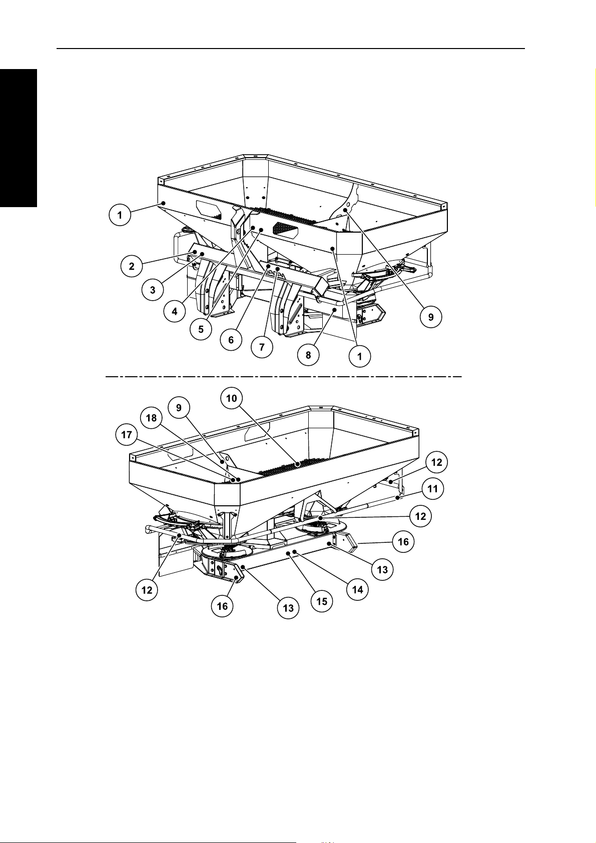
AXIS 20.1/30.1/40.1
Figure 3.1: Position of protection devices, warning and instruction notices and reflectors
[1] White reflector in front
[2] Nameplate
[3] Serial number
[4] Warning: read operator's manual
[5] Warning: material throw-out
[6] Warning: maximum payload
[7] Warning: PTO speed
[8] Spreading disc cover
[9] Instructions: eyelet in hopper
14
[10] Protective grid in hopper
[11] Deflector bracket
[12] Instructions: no climbing
[13] Red reflector
[14] Warning: remove ignition key
[15] Warning: moving parts
[16] Yellow side reflector
[17] Protective grid lock
[18] Instructions: protective grid lock
Page 27
AXIS-GENERAL
AXIS 50.1 W
Safety
3
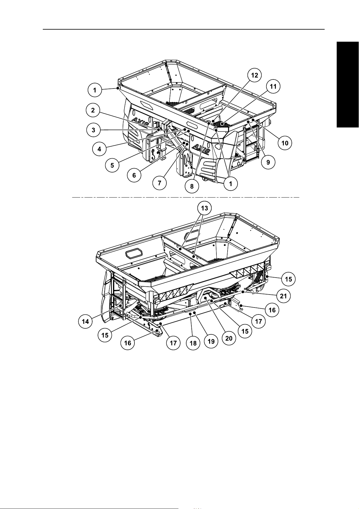
Figure 3.2: Position of protection devices, warning and instruction notices and reflectors
[1] White reflector in front
[2] Nameplate
[3] Serial number
[4] Warning: read operator's manual
[5] Warning: material throw-out
[6] Warning: maximum payload
[7] Warning: PTO speed
[8] Protective grid lock
[9] Instructions on going uphill
[10] Warning: passenger transport prohibited
[11] Protective grid in hopper
[12] Instructions: protective grid lock
[13] Instructions: eyelet in hopper
[14] Spreading disc cover
[15] Instructions: no climbing
[16] Yellow side reflector
[17] Red reflector
[18] Warning: moving parts
[19] Warning: remove ignition key
[20] Gear protective cover
[21] Deflector bracket
15
Page 28
Safety 3
AXIS-GENERAL
[1] Drive shaft cover
3.10.2 Protective device functions
Figure 3.3: Drive shaft
The protective devices protect your life and limb.
Always operate the solid fertiliser broadcaster with effective protective equip-
ment.
Do not use the deflector bracket to climb up on the machine. It is not designed
for this. You may be in danger of falling.
Designation Function
Protective grid in the
hopper
Prevents the intake of body parts by the rotating agitator.
Prevents body parts from being cut off by the metering
slide.
Prevents faults caused by lumps in the spreading material, large stones or other large-scale objects
(screening effect) during the spreading process.
Protective grid lock Prevents the inadvertent opening of the protective grid
in the hopper. Engages mechanically if protective grid
is closed properly. Can be opened by using a tool.
Deflector bracket Protection against getting caught by the rotating
spreading discs from behind and from the side.
16
Spreading disc cover Protection against getting caught by the rotating discs
from the front.
Prevents the casting of fertiliser towards the front side
(in the direction of the tractor and driver).
Drive shaft shield Prevents the intake of body parts into the rotating drive
shaft.
Toothed segment protective cover
Only included with AXIS 50.1 W: prevents body
parts from getting crushed by moving machinery parts.
Page 29

AXIS-GENERAL
3.11 Warning and instruction message stickers
The solid fertiliser broadcaster of the AXIS series has various warning and instruction messages affixed to it (for an illustration please see figure 3.1
figure 3.2
These warning and instruction messages are a part of the machine. They may
neither be removed nor modified. Missing or unreadable warning and instruction
stickers must be replaced immediately.
If parts have been replaced with new ones, it should be made sure that the new
parts have the same warning and instruction stickers as the previous ones.
The correct warning and instruction notices can be obtained from the spare
parts service.
).
NOTICE
Safety
and
3
17
Page 30
Safety 3
AXIS-GENERAL
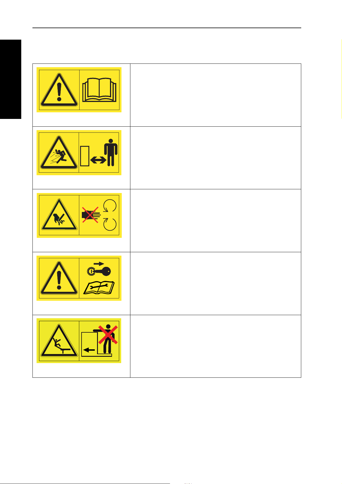
3.11.1 Warning stickers
Read instruction manual and warning messages.
Read and understand the instruction manual before operating the machine.
The operator's manual explains in detail how to operate the
spreader and contains valuable information on operation,
care and maintenance.
Danger through ejection of material
Risk of injury to the entire body through rapidly ejected
spreading material
Please direct all persons out of the danger zone (spreading
zone) before operating the solid fertiliser broadcaster.
Danger from moving parts
Danger of amputation of body parts
Reaching into the danger areas of the rotating spreading
discs, the agitator or the drive shaft is prohibited.
Before carrying out repair and adjustment work, shut off engine and remove the key.
Remove the ignition key.
Before carrying out repair and maintenance work, shut off
engine and remove the key.
Only for AXIS 50.1 W: Riding prohibited
Risk of slipping and injury. Do not climb on the steps of the
solid fertiliser broadcaster during spreading and transport.
18
Page 31

AXIS-GENERAL
3.11.2 Instruction stickers and factory plate
2056545
2055689
Safety
Only for AXIS 50.1 W: Steps
Climbing on the retracted steps is prohibited.
Only climb on the steps when it is extended.
Only travel on the road with the steps retracted.
Ring eyelets on the hopper
The brackets used for the fastening of the lifting
gear
3
2052291
Climbing prohibited
Climbing on the deflector bracket is prohibited.
Protective grid lock
The grid lock is automatically locked when the
protective grid in the hopper is closed properly.
It can only be unlocked by using a tool.
Rated speed of PTO shaft
The rated speed of the PTO shaft is 540 r.p.m.
540
min
-1
19
Page 32

Safety 3
AXIS-GENERAL
2056779
750
min
-1
2100 kg
2055654
max.
3000 kg
2052173
max.
4000 kg
2056096
max.
Landmaschinenfabrik GmbH
D-76545 Sinzheim
Typ:
Masse: Baujahr:kg
12345
Rated speed of PTO shaft
(optional, gearbox at 750 r.p.m.)
The rated speed of the PTO shaft is 750 U/min.
Maximum loading capacity (depending on
model)
3.12 Reflectors
The solid fertiliser broadcaster of the AXIS series is factory fitted with front, back
and side identification (For an illustration of the positioning on the machine, see
figure 3.1
Nameplate
Serial number
and figure 3.2).
20
Page 33

Technical data
AXIS-GENERAL
4 Technical data
4. 1 Machine information
4.1.1 Manufacturer
KUHN SA
F-67706 Saverne Cedex
Tel.: +33 (0)3 88 01 81 00
Fax.: +33 (0)3 88 01 81 01
Internet: www.kuhn.com
4.1.2 Versions
Model AXIS 20.1 AXIS 30.1 AXIS 40.1 AXIS
50.1 W
4
Function Q KRDQKRDWQKRDW W
Spreading speed, depending
on travellingspeed
Single-acting hydraulic cylinder
Single-acting hydraulic cylinder with two way unit
Double-acting hydraulic cylinder
Weighing spreader
Electrical application point
adjustment
21
Page 34

Technical data 4
AXIS-GENERAL
4.1.3 Specifications of base equipment
Dimensions:
Data AXIS
20.1
Overall width 240 cm
Overall length 141.5 cm
Fill height (basic ma-
95 cm
chine)
Distance of centre of
65.5 cm
gravity from lower
steering arm
Fill width 230 cm
Working width
PTO speed
2
1
12 - 28 m 12 - 42 m 12 - 42 m 12 - 42 m 12 - 42 m 18 - 50 m
min. 450 450 450 450 450 450
max. 650
Capacity 1000 l
Mass flow
3
Hydraulic pres-
max. 400 kg/min 500 kg/min 500 kg/min 500 kg/min 500 kg/min 500 kg/min
max. 200 bar
sure
Noise level
(measured
75 dB (A) 75 dB (A) 75 dB (A) 75 dB (A) 75 dB (A) 75 dB (A)
4
in the closed tractor
driver's cab)
AXIS
30.1
AXIS
30.1 W
AXIS
40.1
AXIS
40.1 W
AXIS
50.1 W
240 cm 240 cm 240 cm 240 cm 290 cm
141.5 cm 145,0 cm 141.5 cm 145,0 cm 161,0 cm
101 cm 101 cm 101 cm 101 cm 125 cm
65.5 cm 72.5 cm 65.5 cm 72.5 cm 74.5 cm
230 cm 230 cm 230 cm 230 cm 270 cm
650 650 650 650 650
1200 l 1200 l 1200 l 1200 l 2000 l
200 bar 200 bar 200 bar 200 bar 200 bar
1. Working width dependent on fertiliser and casting disc type
2. Optional: gearbox with 750 rpm, max. 900 rpm
3. Max. mass flow dependent on fertiliser type
4. Since the noise level of the solid fertiliser broadcaster can only be determined when the tractor is running, the actual
measured value is greatly dependent on the tractor type being used.
22
Page 35

Technical data
AXIS-GENERAL
Weights and loads:
NOTICE
The unladen weight (mass) of the solid fertiliser broadcaster varies depending
on the feature package and attachment combination. The unladen weight
(mass) shown on the factory plate refers to the standard version.
4
Data AXIS
20.1
Unladen weight 295 kg 320 kg 375 kg 330 kg 385 kg 680 kg
Fertiliser loading capacity
4.1.4 Specifications of extensions and extension combinations
Solid fertiliser broadcaster AXIS can be operated with different extensions and
combinations of extensions. Depending on the feature package the capacity, dimensions and weights may change.
Extension combination AXIS 20.1
Change in capacity + 600 l + 800 l + 1100 l
Change in fill height 0 + 26 cm + 24 cm
Extension size max. 240 x 130 cm 280 x 130 cm
Extension weight 30 kg 45 kg 60 kg
max.
2100 kg 3000 kg 4000 kg
L603 L800 XL1103
AXIS
30.1
AXIS
30.1 W
AXIS
40.1
AXIS
40.1 W
AXIS
50.1 W
Notes 3-side 4-side 3-side
23
Page 36

Technical data 4
AXIS-GENERAL
AXIS 30.1, AXIS 40.1
Extension combination L603 L800 L1500 XL1103 XL1300 XL1800
Change in capacity + 600 l + 800 l + 1500 l + 1100 l + 1300 l + 1800 l
Change in fill height 0 + 26 cm + 50 cm + 24 cm + 38 cm + 52 cm
Extension size max 240 x 130 cm 280 x 130 cm
Extension weight 30 kg 45 kg 75 kg 60 kg 65 kg 85 kg
Notes 3-side 4-side 4-side3-side4-side4-side
AXIS 50.1 W
Extension combination GLW1000 GLW2000
Change in capacity + 1000 l + 2000 l
Change in fill height + 22 cm + 44 cm
Extension size max. 290 x 150 cm
Extension weight 52 kg 86 kg
Notes 4-side 4-side
24
Page 37

AXIS-GENERAL
4. 2 List of available optional equipment
We recommend that you have the extra equipment fitted and mounted on the
basic machine by your supplier or an authorised service centre .
4.2.1 Extensions
The holding capacity of the spreader can be increased by extending the main
hopper by an hopper extension.
The extensions are bolted to the standard unit.
For an overview of extensions and extension combinations see Chapter
4.1.4:
Specifications of extensions and extension combinations, page 23.
NOTICE
NOTICE
Technical data
4
4.2.2 Hopper covers
A hopper cover can be installed to protect the spreader material from rain and
moisture.
The hopper covers are screwed both to the main hopper and to the hopper extension.
Hopper covers Application
AP-L 25, foldable
AP-XL 25, foldable Attachments: XL11031, XL1300, XL1800
AP-L 50, foldable
1. A supplementary hopper cover is necessary for this attachment.
4.2.3 Hopper cover supplement
For the hopper extensions L603 and XL1103, a supplementary cover is necessary in addition to the hopper cover.
Standard unit
Attachments: L603
Attachments: GLW1000, GLW2000
1
, L800, L1500
Cover supplements Application
APE-L 25, foldable
APE-XL 25, foldable
Extension: L603
Extension: XL1103
25
Page 38

Technical data 4
AXIS-GENERAL
4.2.4 TELIMAT T 25, T 50
The Telimat is used for remote-controlled boundary spreading from the track
(right).
A single action valve is required for the operation of the TELIMAT T 25 or T 50.
4.2.5 Two way unit (only for AXIS 20.1/30.1/40.1)
The two way unit can be used to connect the solid fertiliser broadcaster to tractors
with only one single-acting control valve.
4.2.6 Tele-Space universal drive shaft
The Tele-Space universal drive shaft is extendable and provides additional space
(approx. 300 mm) for easier coupling of the solid fertiliser broadcaster to the tractor.
A separate assembly manual is supplied with the Tele-Space universal drive
shaft.
4.2.7 Universal drive shaft with radial ratchet brace (only for AXIS 20.1)
The radial ratchet brace coupling limits the torque in case of overloading.
4.2.8 Auxiliary lighting
The solid fertiliser broadcaster can be fitted with auxiliary lighting.
Lighting Application
BLO 25/50
BLW 20/25/50
BLF 25/50
BLF
Lighting for rear
without warning sign
Lighting for rear
with warning sign
Lighting for front
with warning sign
for wide attachments
Lighting for front
without warning sign
26
for wide attachments
NOTICE
Attachments are subject to the lighting regulations specified in the traffic regulations. Observe the traffic regulations of your country.
Page 39

Technical data
AXIS-GENERAL
4.2.9 ASR 25 transport wheels with bracket
For parking and manually pushing the empty solid fertiliser broadcaster.
The transport wheels consist of two turning wheels in front and two non turning
wheels at the rear without wheel lock.
4.2.10 Border spreading unit GSE 25 (only for AXIS 20.1/30.1/40.1)
Limits the spreading width (either towards the left or right) to the range between
approx. 0.5 m and 2 m from the centre of the tractor track to the outer edge of the
field. The metering slide that points to the field edge is closed.
Fold the border spreading unit downwards for border spreading.
The border spreading unit must be hinged up again before two-sided spread-
ing.
4.2.11 Hydraulic remote controller FHZ 25 for GSE 25 (only for AXIS 20.1/30.1/40.1)
This remote controller is used, from the tractor cab, to hydraulically swing the
GSE 25 border spreading unit into position or to swing it from border spreading
position to the both side spreading position.
4
For operating the hydraulic remote controller FHZ 25, a single action valve is required
4.2.12 Hydraulic remote controller FHZ 26 for GSE 25 (only for AXIS 30.1 W/40.1 W)
This remote controller is used, from the tractor cab, to hydraulically swing the
GSE 25 border spreading unit into position or to swing it from border spreading
position to the both side spreading position.
For operating the hydraulic remote controller FHZ 26, a single action valve is required.
4.2.13 Dirt deflector SFG 30 (only for AXIS 20.1)
This attachment prevents the solid fertiliser broadcaster and extra equipment
from getting dirty by dirt thrown up by the wheels of the tractor.
Apart from that, the dirt deflector also prevents foreign bodies from being caught
and flung out by the spreading discs.
4.2.14 Dirt deflector extension SFG-E 30 (only for AXIS 30.1/40.1)
If the deflector SFG 30 does not perform satisfactorily, the SFG-E 30 extension
can be mounted additionally.
27
Page 40

Technical data 4
AXIS-GENERAL
4.2.15 Spreading vane set Z14, Z16, Z18
This set of spreading vanes is used for spreading snail bait. The snail bait spreading vane replaces the short spreading vane on the right and left spreading discs.
Set Application
Z14
Z16
Z18
4.2.16 Inspection kit PPS5
For checking cross-distribution in the field.
4.2.17 Fertiliser Identification System DiS
Rapid, uncomplicated determination of spreader settings with unfamiliar fertilisers.
Spreading disc S4
Spreading disc S6
Spreading disc S8
28
Page 41

AXIS-GENERAL
5 Axle load calculation
5.1 Calculation of the total weight
Overload danger
Mounted units on the front or rear three-point linkage must not
cause the approved total weight to be exceeded. The front axle of
the tractor must always be loaded with at least 20 % of the
unladen weight of the tractor.
Before using the unit make sure that it meets these require-
ments by performing the following calculations or weighing
the tractor-unit combination.
n CAUTION
Axle load calculation
5
Calculation of the
total weight, the
axle loads and the
tyre capacity and
the required ballast weights.
G
V
T
V
abcd
Bild 5.1: Loads and weights
G
H
T
H
29
Page 42

Axle load calculation 5
AXIS-GENERAL
You will need the following data for the calculation:
Character
[unit]
T
[kg] Unladen weight of tractor. [1]
L
[kg] Front-axle load of the unladen tractor. [1]
T
V
[kg] Rear-axle load of the unladen tractor. [1]
T
H
[kg] Total weight of front-mounted unit or front bal-
G
V
Meaning Calculation
by
[2]
last.
[kg] Total weight of rear-mounted unit or rear ballast. [2]
G
H
a [m] Distance between centre of gravity of front-
[2], [3]
mounted unit or front ballast and centre of front
axle.
b [m] Wheel base of tractor. [1], [3]
c [m] Distance between centre of rear axle and centre
[1], [3]
of lower link ball.
d [m] Distance between centre of lower link ball and
[2]
centre of gravity of rear-mounted unit or rear
ballast.
[1] See tractor operator's manual
[2] See equipment price list and/or operator's manual
[3] Measuring
30
Page 43

AXIS-GENERAL
Rear-mounted unit or front-rear combinations
G
Vmin
G
H
cd+()• TVb02TLb••,+•–()
ab+
---------------------------------------------------------------------------------------------=
G
Hmin
GVa• THb 0 45 TLb••,+•–()
bcd++
----------------------------------------------------------------------------------=
T
Vtat
G
V
ab+()• TVbG
H
–cd+()••+()
b
-------------------------------------------------------------------------------------------=
Calculation of minimum ballast at
front G
V min
Enter the calculated minimum ballast requirement in the table.
Front-mounted unit
Calculation of the minimum ballast at
rear G
H min
Axle load calculation
5
Enter the calculated minimum ballast requirement in the table.
If the front-mounted unit (GV) is lighter than the minimum ballast at the front (G
), the weight
V min
of the front-mounted unit must be increased to at least the weight of the minimum front ballast.
Calculation of the actual front-axle
load T
V tat
Enter the calculated actual and approved front-axle load as specified in the tractor operator's
manual in the table.
31
Page 44

Axle load calculation 5
AXIS-GENERAL
G
tat
G
V
TLG
H
++()=
T
H
tat
G
tat
G
Vtat
–()=
If the rear-mounted unit (GH) is lighter than the minimum ballast at the rear (G
), the weight
Hmin
of the rear-mounted unit must be increased to at least the weight of the minimum rear ballast.
Calculation of the actual total weight
G
tat
Enter the calculated actual and approved total weight as specified in the tractor operator's manual
in the table.
Calculation of the actual rear-axle
load T
H tat
Enter the calculated actual and approved rear-axle load as specified in the tractor operator's manual in the table.
Tyre load capacity
Enter double the value (two tyres) of the approved tyre load capacity (for example, see tyre manufacturer's documentation) in the table.
5.2 Axle loads table
Actual value from
calculation
Minimum ballast
kg ⎯⎯
front/rear
Total weight kg ≤ kg ⎯
Front-axle load kg ≤ kg ≤ kg
Rear-axle load kg ≤ kg ≤ kg
Approved value
from operator's
manual
Twice approved
tyre load capacity
(two tyres)
32
The minimum ballast weight must be mounted on the tractor as an attachment
or as ballast.
The calculated values must be less than or equal to the permitted values.
Page 45

AXIS-GENERAL
6 Transport without tractor
6.1 General safety instructions
Before transporting the solid fertiliser broadcaster observe the following
instructions:
The solid fertiliser broadcaster must only be transported without the tractor if
the hopper is empty.
The operation must only be carried out by suitable, trained and expressly au-
thorised personnel.
Suitable means of transportation and lifting equipment (e.g. crane, fork lift
truck, cable devices...) are to be used for transport purposes.
Establish the transportation route in good time and remove possible obsta-
cles.
A check must be made to ascertain that all safety and transport devices are
fit for operation.
Cordon off all danger areas accordingly, even if they are only briefly in exist-
ence.
Transport without tractor
6
The person responsible for the transportation is required to make certain, that
the transport of the solid fertiliser broadcaster can be carried out routinely.
Unauthorised persons are to be excluded from the transport route. The areas
concerned are to be cordoned off!
The solid fertiliser broadcaster is to be handled and transported carefully.
Make sure that allowance is made for the centre of gravity! If necessary, ad-
just the cables such that the machine is correctly aligned on the means of
transport.
Transport the solid fertiliser broadcaster to the set-up location as close to the
ground as possible.
6.2 Loading and unloading, parking
1. Determine the weight of the solid fertiliser broadcaster.
Check the details on the factory type plate.
If applicable, note the weight of the special built-on accessories.
2. Hang suitable lifting tackle in both ring eyelets.
3. Lift the machine carefully using suitable lifting equipment.
4. Place the machine carefully on the loading platform of the transport vehicle or
on solid ground.
33
Page 46

Transport without tractor 6
AXIS-GENERAL
34
Page 47

Instructions regarding the spreading process
AXIS-GENERAL
7 Instructions regarding the spreading process
The intended use of the solid fertiliser broadcaster includes compliance with the
operating, maintenance and service conditions according to manufacturer specifications. Spreading therefore always includes the work of preparation and
cleaning/maintenance.
Conduct spreading as described below.
Preparation
Attach spreader to tractor page 42
Close metering slide
Preset the mounting height page 46
Fill hopper Chapter A.2 or Chapter A.3
Set application rate Chapter B.2
Setting the working width
Chapter B.5
7
1
1
1
- Choosing the correct spreading disc
- Set fertiliser drop point
Chapter B.5.3
Spreading
Travel to the spreading location
Check mounting height
Engage PTO shaft
Open slide and start spreading
Finish spreading run and close the outlets
Disengage PTO shaft
Discharge residue Chapter B.10
Cleaning/maintenance
Open metering slide
Unhitch spreader from tractor
Maintenance and lubrication Chapter C
1
and AXIS-Main-
tenance
1
1
1. See the solid fertiliser broadcaster register (AXIS 20.1, AXIS 30.1/40.1 or AXIS 50.1 W)
35
Page 48

Instructions regarding the spreading process 7
AXIS-GENERAL
36
Page 49

Standard operating procedure (all models)
AXIS-GENERAL
8 Standard operating procedure (all models)
8. 1 Taking delivery of the solid fertiliser broadcaster
Please check that all parts are included when the solid fertiliser broadcaster is delivered.
The standard equipment includes
1 solid fertiliser broadcaster of the AXIS series,
1 operator’s manual AXIS 20.1, AXIS 30.1, AXIS 40.1, AXIS 50.1 W
1 calibration chart (Paper or CD),
1 calibration kit comprising chute and calculator,
lower and upper steering arm pins,
1 spreading disc set (according to order),
1 universal drive shaft (including operator's manual).
1 agitator
8
1 protective grid in the hopper
version Q or W of the solid fertiliser broadcaster: electronic control
Please check any accessories that you ordered.
Check and make sure that no damage occured to the machine during transport
and that no parts are missing. Have the transport damages be confirmed by the
transport company.
When receiving the machine, check that all attached components are correctly
and tightly seated.
The right and left casting discs must be mounted facing the direction of travel.
In case of doubt, please contact your dealer or our factory.
8. 2 Tractor requirements
The tractor must meet the required mechanical, hydraulic and electrical requirements for safe and correct operation of the solid fertiliser broadcaster of the AXIS
series.
NOTICE
universal drive shaft connection: 1 3/8 inches, 6-spline, 540 rpm,
Oil feed: max. 200 bar, single or double action valve (depending on equip-
ment)
On board voltage: 12 V,
Three point linkage category II.
37
Page 50

Standard operating procedure (all models) 8
AXIS-GENERAL
8. 3 Mounting the drive shaft on the solid fertiliser broadcaster
n CAUTION
Danger from unsuitable drive shaft.
The solid fertiliser broadcaster is fitted with a universal drive shaft
type designed for the unit and the power.
Use only universal drive shafts approved by the manufacturer.
Follow the directions in the shaft manufacturer's manual!
The solid fertiliser broadcaster can be delivered with various kinds of drive shafts,
depending on model:
universal drive shaft with shear bolt clutch,
universal drive shaft with radial pin clutch,
Tele-Space universal drive shaft with radial pin clutch.
The drive shaft with shear pin attachment can only be mounted on the solid
fertiliser broadcaster of the type AXIS 20.1. See „
with shear bolt coupling on the AXIS 20.1.“ on page 73.
8.3.1 Fitting and removing the drive shaft
Attachment:
1. Check the attachment position.
The end of the shaft with the tractor symbol must be at the tractor end of
the shaft.
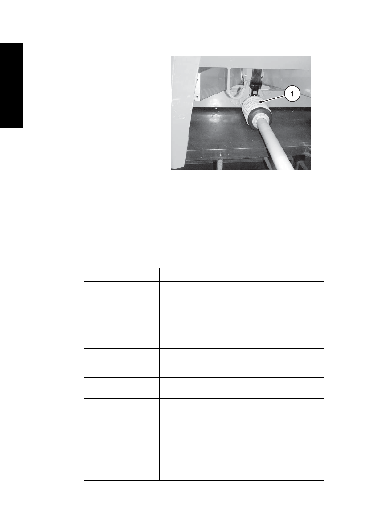
2. Release the drive shaft [1]
locking screw.
3. Turn the drive shaft shield to
the demounting position.
NOTICE
Mount universal drive shaft
38
4. Pull the universal drive shaft
out.
Figure 8.1: Remove drive shaft shield
Page 51

Standard operating procedure (all models)
AXIS-GENERAL
5. Remove the spigot protec-
tion and grease the transmission spigot. Mount the
drive shaft onto the transmission spigot.
8
6. Tighten hexagonal screw
and nut with size 17 wrench
(max. 35 Nm).
Figure 8.2: Mount the drive shaft onto the
transmission spigot
Figure 8.3: Tighten drive shaft
39
Page 52

Standard operating procedure (all models) 8
AXIS-GENERAL
7. Slide drive shaft shield with
hose clamp over the universal drive shaft and place on
the gearbox neck (do not
tighten).
8. Turn the drive shaft shield to
the locking position.
9. Tighten locking screw.
10. Tighten hose clamp.
Figure 8.4:
Figure 8.5: Secure universal drive shaft
Put the drive shaft shield back on
shield
40
Page 53

Standard operating procedure (all models)
AXIS-GENERAL
Instructions for removal:
Remove the universal drive shaft in reverse order of attachment.
Do not use safety chain to suspend the universal drive shaft.
Store uncoupled universal drive shaft on the bracket.
8
Figure 8.6: Universal drive shaft in bracket
41
Page 54

Standard operating procedure (all models) 8
AXIS-GENERAL
8. 4 Attaching solid fertiliser broadcaster to the tractor
8.4.1 Requirements
n DANGER
Danger from unsuitable tractor
Use of an unsuitable tractor for the solid fertiliser broadcaster of
the AXIS series can lead to the severest accidents during operation and transport.
Use only tractors that comply with the technical requirements of
the solid fertiliser broadcaster.
Check the vehicle documentation to make sure that your
tractor is suitable for the solid fertiliser broadcaster of the
AXIS series.
Check the following points in particular:
Are the tractor and the solid fertiliser broadcaster safe to operate?
Does the tractor comply with the mechanical, hydraulic and electrical require-
ments? (see „
Do the attachment categories of the tractor and solid fertiliser broadcaster
Tractor requirements“ on page 37).
match (consult the dealer if necessary)?
Is the solid fertiliser broadcaster securely positioned on a firm, level surface?
Do the axle loadings conform to the stipulated calculations (see
„
Axle load calculation“ on page 29)?
42
Page 55

AXIS-GENERAL
8.4.2 Attachment
The solid fertiliser broadcaster is attached to the three-point linkage of the tractor.
Standard operating procedure (all models)
n DANGER
Danger of being crushed between tractor and the
solid fertiliser broadcaster
Persons present between the tractor and the solid fertiliser broadcaster when the tractor is approaching or when the hydraulics are
actuated are risking their lives.
The tractor may brake too late or not at all because of inattention
or faulty operation.
Ensure that there is no one present between the tractor and
the solid fertiliser broadcaster.
NOTICE
8
For normal fertilisation and late fertilisation always use the upper coupling
points of the solid fertiliser broadcaster. See figure 8.7
.
Figure 8.7: Mounting position
43
Page 56

Standard operating procedure (all models) 8
AXIS-GENERAL
Mounting instructions:
The machine can be connected to the tractor with class III linkage only with
class II clearance and the use of reducing sleeves.
The bottom and top linkage pins must be locked with the locking pins or spring
clips.
The solid fertiliser broadcaster must be mounted as specified in the calibra-
tion charts for correct cross distribution of the fertiliser.
To avoid a seesawing motion during operation, make sure that the solid ferti-
liser broadcaster does not have too much sideways play:
- Lower steering arms of the tractor should be braced by stabilising struts
or chains.
1. Start the tractor.
The PTO shaft is switched off.
2. Drive the tractor into coupling position towards the solid fertiliser broadcaster.
Do not latch the lower steering arm hooks into place yet.
Make sure there is enough space between the tractor and the solid ferti-
liser broadcaster to be able to connect the drive shaft and control elements.
3. Turn off the tractor. Remove the ignition key.
4. Connect the drive shaft to the tractor.
If there is not enough space available, then an extendable Tele-Space
universal drive shaft must be used for safety reasons.
5. Connect the electrical and hydraulic slide feed controls and the lighting (see
Section A.1 of each solid fertiliser broadcaster model).
6. From the tractor cab, couple the lower steering arm hook and the upper steer-
ing arm to the retainers provided for them, as described in the operator's manual for your tractor.
NOTICE
We recommend using lower arm hooks with a hydraulic upper arm for safety
and comfort. See figure 8.7
.
7. Check if the solid fertiliser broadcaster is stable.
8. Carefully raise the fertiliser spreading arm to maximum allowed lifting height.
44
Page 57

Standard operating procedure (all models)
AXIS-GENERAL
n CAUTION
Material damage due to too long drive shaft
When the solid fertiliser broadcaster is lifted up, the drive shaft
halves can come into contact inside each other. This can cause
damage to the drive shaft, transmission or the solid fertiliser
broadcaster.
Check the free space between the solid fertiliser broad-
caster and the tractor.
Make sure that there is enough space between the drive
shaft outer pipe (at least 20 to 30 mm) and the protective
cone on the spreading side.
9. Shorten the drive shaft, if needed.
NOTICE
8
Have the universal drive shaft shortened only by your dealer or your expert
workshop.
NOTICE
Observe the attachment instructions and short introduction in the shaft manufacturer's manual when testing and fitting the universal drive shaft. This operator's manual is attached to the universal drive shaft on delivery.
10. Preset mounting height according to the calibration chart. See 8.6.2:
as per calibration chart, page 52.
Settings
45
Page 58

Standard operating procedure (all models) 8
AXIS-GENERAL
8. 5 Preset the mounting height
8.5.1 Safety
Danger of being crushed under falling spreader
If the two halves of the upper steering arm are brought totally apart
from each other by mistake, it can happen that the steering arm
cannot compensate for the weight of the full load of fertiliser,
resulting in the solid fertiliser broadcaster abruptly falling over or
falling down backwards.
Persons can be seriously hurt and the machine damaged.
If you want to extend the upper steering arm, please always
take the maximum allowed extension length given by the
tractor or steering arm manufacturer into account.
Clear the area of any persons who might be present in the
danger zone of the solid fertiliser broadcaster.
n DANGER
n WARNING
Risk of injury from rotating machine components
Contact with the spreading equipment (spreading discs, spreading
vanes) may injure, crush or cut off body parts. Body parts or
objects may be caught and pulled in.
Never exceed the maximum approved hopper heights at
the front (V) and rear (H).
General instructions before setting the mounting height
We recommend that you choose the highest coupling point on the tractor to
connect the upper steering arm to, particularly for high lifting heights.
NOTICE
For normal as well as late fertilisation, always use the upper couplings of the
solid fertiliser broadcaster.
The lower coupling points on the solid fertiliser broadcaster which are meant
for the lower steering arms of the tractor, should be used only in exceptional
circumstances during late fertilisation.
46
Page 59

Standard operating procedure (all models)
AXIS-GENERAL
V
H
8.5.2 Maximum approved hopper mounting height at front (V) and rear (H)
The maximum approved hopper height (V + H) is measured from the ground
to the bottom edge of the frame.
8
Figure 8.8: Maximum approved hopper mounting height V and H during nor-
mal and late fertilisation
The maximum approved hopper height depends on the following factors:
Normal or late fertilisation.
Spreader equipment Maximum approved hopper mounting height
during normal fertilisation during late fertilisation
V [mm] H [mm] V [mm] H [mm]
AXIS 20.1
AXIS 30.1/AXIS 40.1
AXIS 50.1 W 990 990 900 960
1040 1040 950 1010
47
Page 60

Standard operating procedure (all models) 8
AXIS-GENERAL
8.5.3 Hopper mounting heights A and B as per the spreading calibration chart
The hopper mounting heights in the calibration chart (A and B) are always measured in the field from the top of the crop height to the bottom edge of the frame.
NOTICE
The values of A and B are taken from the calibration charts.
Setting the mounting height during normal fertilisation
Requirements:
The solid fertiliser broadcaster should be connected to the tractor at the high-
est connecting point of the steering arm.
The lower arm of the tractor should be connected to the upper coupling
point of the lower steering arm of the solid fertiliser broadcaster.
Proceed as follows when determining the hopper height (in normal fertilisation):
1. Determine the hopper heights A and B (above crop) from the calibration
chart.
2. Compare the hopper heights A and B (plus the crop height) with the maximum approved hopper mounting heights at the front (V) and rear (H).
48
Page 61

Standard operating procedure (all models)
AXIS-GENERAL
8
Figure 8.9: Mounting position and height during normal fertilisation
The following applies:
AXIS20.1
AXIS30.1/ AXIS40.1
A + crop height ≤ V Max. 1040 mm Max. 990 mm
B + crop height ≤ H Max. 1040 mm Max. 990 mm
3. If the maximum approved mounting height of the solid fertiliser broadcaster is
exceeded or the mounting heights A and B cannot be reached, then the solid
fertiliser broadcaster should be mounted according to late fertilisation calibration values.
AXIS 50.1 W
49
Page 62

Standard operating procedure (all models) 8
AXIS-GENERAL
Setting the mounting height during late fertilisation
Requirements:
The solid fertiliser broadcaster should be connected to the tractor at the high-
est coupling point of the upper steering arm.
The lower arm of the tractor should be connected to the upper coupling
point of the lower steering arm of the solid fertiliser broadcaster.
Proceed as follows when determining the hopper mounting height (during late fertilisation ):
1. Determine the hopper mounting heights A and B (above crop) from the calibration chart.
2. Compare the hopper heights A and B (plus the crop height) with the maximum approved hopper mounting heights at the front (V) and rear (H).
50
Figure 8.10: Mounting position and height during late fertilisation
The following applies:
AXIS 20.1
AXIS 50.1 W
AXIS 30.1/AXIS 40.1
A + crop height ≤ V Max. 950 mm Max. 900 mm
B + crop height ≤ H Max. 1010 mm Max. 960 mm
Page 63

Standard operating procedure (all models)
AXIS-GENERAL
3. If the lifting height of the tractor is not enough to be able to set the required
mounting height, you can use the lower coupling point on the lower arm of the
solid fertiliser broadcaster.
NOTICE
Make sure that the maximum allowed length of the upper arm is not exceeded.
Please note the instructions in the operating manuals of the tractor and
steering arm.
8
Figure 8.11: Solid fertiliser broadcaster mounted to the lower coupling point of
the lower steering arm
The following applies:
AXIS 20.1
AXIS 50.1 W
AXIS 30.1/AXIS 40.1
A + crop height ≤ V Max. 950 mm Max. 900 mm
B + crop height ≤ H Max. 1010 mm Max. 960 mm
51
Page 64

Standard operating procedure (all models) 8
AXIS-GENERAL
8. 6 Using the spreading calibration chart
8.6.1 Information on the calibration chart
The values in the calibration chart have been determined using the solid fertiliser
broadcaster testing rig.
The fertilisers used have been procured from fertiliser manufacturers or from storage depots. Experience shows that your spreading materials - even with identical
specifications - may have different spreading properties because of storage,
transport and many other reasons.
This means that application of the settings for the solid fertiliser broadcaster given
in the calibration chart could result in a different spreading volume or poor distribution of spreading material.
Therefore observe the following instructions:
Always check the actual spreading material volume by performing a calibra-
tion test (see chapter B.6 for each model of the solid fertiliser broadcaster).
Check the working width of the fertiliser distribution with a practice test kit (op-
tion).
Use only fertilisers listed in the spreading calibration charts.
Please contact us if you do not find a particular fertiliser type mentioned in the
calibration charts.
Follow the settings exactly. Even a slightly incorrect setting may adversely affect the spreading pattern.
When using urea note particularly the following:
Because of fertiliser imports, urea is available in widely varying qualities and
particle sizes. This may make different spreader settings necessary.
Urea is more sensitive to wind and absorbs more moisture than other fertilis-
ers.
The operator is responsible for making the correct settings according to the fertiliser in use.
We point out specifically that we do not accept any liability for damage resulting
from incorrect spreader settings.
8.6.2 Settings as per calibration chart
NOTICE
52
The operator determines the hopper mounting height, fertiliser drop point, metering slide adjustment, spreading disc type and PTO speed for optimum spreading
from the calibration chart depending on fertiliser type, working width, application
rate, ground speed and fertilisation method.
Page 65

Standard operating procedure (all models)
AXIS-GENERAL
Example of spreading during normal fertilisation
Figure 8.12: Spreading during normal fertilisation
Field spreading in normal fertilisation yields a symmetrical scatter pattern. If the
spreader is correctly set (see information in the calibration charts), the fertiliser is
spread evenly over the field.
Specified parameters:
Fertiliser type: KAS BASF
8
Application rate: 300 kg/ha
Working width: 24 m
Ground speed: 12 km/h
The following settings should be applied on the solid fertiliser broadcaster according to the spreading calibration chart:
Hopper height: 50/50 (A = 50 cm, B = 50 cm)
Fertiliser drop point: 6
Metering slide adjustment: 180
Spreading disc type: S4
PTO speed: 540 rpm
53
Page 66

Standard operating procedure (all models) 8
AXIS-GENERAL
Example of border spreading during normal fertilisation
(Optional equipment TELIMAT T 25, T 50):
Figure 8.13: Border spreading in normal fertilisation
During border spreading in normal fertilisation, almost no fertiliser goes beyond
the field boundary. Underfertilisation at the field boundary must be accepted in
this case.
Specified parameters:
Fertiliser type: KAS BASF
Application rate: 300 kg/ha
Working width: 24 m
Ground speed: 12 km/h
The following settings should be applied on the solid fertiliser broadcaster according to the spreading calibration chart:
Hopper height: 50/50 (A = 50 cm, B = 50 cm)
Fertiliser drop point: 6
Metering slide adjustment: 180 left, 150 right
Spreading disc type: S4
PTO speed: 540 rpm
TELIMAT settings: K12.5
1. recommended volume reduction of 20% on boundary spreading side
1
54
Page 67

Standard operating procedure (all models)
AXIS-GENERAL
Example of boundary spreading during normal fertilisation
(Optional equipment TELIMAT T 25, T 50):
Figure 8.14: Boundary spreading in normal fertilisation
Boundary spreading in normal fertilisation refers to a spreading technique in
which a bit more fertiliser lands beyond the boundary of the field. Therefore, there
is just a slight underfertilisation at the field boundary.
Specified parameters:
8
Fertiliser type: KAS BASF
Application rate: 300 kg/ha
Working width: 24 m
Ground speed: 12 km/h
The following settings should be applied on the solid fertiliser broadcaster according to the spreading calibration chart:
Hopper height: 50/50 (A = 50 cm, B = 50 cm)
Fertiliser drop point: 6
Metering slide adjustment: 180
Spreading disc type: S4
PTO speed: 540 rpm
TELIMAT settings: S13
55
Page 68

Standard operating procedure (all models) 8
AXIS-GENERAL
Example of field spreading in late fertilisation
Figure 8.15: Field spreading in late fertilisation
Field spreading in late fertilisation yields a symmetrical spreading pattern. If the
spreader is correctly set (see information in the calibration charts), the fertiliser is
spread evenly over the field.
Specified parameters:
Fertiliser type: KAS BASF
Application rate: 150 kg/ha
Working width: 24 m
Ground speed: 12 km/h
The following settings should be applied on the solid fertiliser broadcaster according to the spreading calibration chart:
Hopper height: 0/6 (A = 0 cm, B = 6 cm)
Fertiliser drop point: 6.5
Metering slide adjustment: 90
Spreading disc type: S4
PTO speed: 540 rpm
56
Page 69

Standard operating procedure (all models)
AXIS-GENERAL
Example of boundary spreading during late fertilisation
(Optional equipment TELIMAT T 25, T 50):
Figure 8.16: Border spreading in late fertilisation
During border spreading in normal fertilisation, almost no fertiliser goes beyond
the field boundary. Underfertilisation at the field boundary must be accepted in
this case.
Specified parameters:
8
Fertiliser type: KAS BASF
Application rate: 150 kg/ha
Working width: 24 m
Ground speed: 12 km/h
The following settings should be applied on the solid fertiliser broadcaster according to the spreading calibration chart:
Hopper height: 0/6 (A = 0 cm, B = 6 cm)
Fertiliser drop point: 6.5
Metering slide adjustment: 90 left, 72 right
Spreading disc type: S4
PTO speed: 540 rpm
TELIMAT settings: K12.5
1. recommended volume reduction of 20% on boundary spreading side
1
57
Page 70

Standard operating procedure (all models) 8
AXIS-GENERAL
Example of boundary spreading during normal fertilisation
(Optional equipment TELIMAT T 25, T 50):
Figure 8.17: Boundary spreading in late fertilisation
Boundary spreading in normal fertilisation refers to a spreading technique in
which a bit more fertiliser lands beyond the boundary of the field. Therefore, there
is just a slight underfertilisation at the field boundary.
Specified parameters:
Fertiliser type: KAS BASF
Application rate: 150 kg/ha
Working width: 24 m
Ground speed: 12 km/h
The following settings should be applied on the solid fertiliser broadcaster according to the spreading calibration chart:
Hopper height: 0/6 (A = 0 cm, B = 6 cm)
Fertiliser drop point: 6.5
Metering slide adjustment: 90
Spreading disc type: S4
PTO speed: 540 rpm
TELIMAT settings: S13
58
Page 71

AXIS-GENERAL
8. 7 Spreading at the headland
For proper spreading at headlands, it is very important to have precise tramlining.
Border spreading
Spreading at the field boundary with the remote-controlled TELIMAT border
spreading unit:
Standard operating procedure (all models)
8
X
X
X
X
X
Figure 8.18: Border spreading
[T] Headland tramline
[X] Working width
Headland tramlining [T] should be laid at a distance of half of the working
width [X] from field boundary.
59
Page 72

Standard operating procedure (all models) 8
AXIS-GENERAL
E
A
X
Normal spreading in/out of the headland tramlining
When continuing spreading in the field after spreading from the headland tramline, please note the following:
Move the border spreading unit TELIMAT out of the spreading area.
Figure 8.19: Normal spreading
[A] End of spreading fan during spreading in the headland tramline
[E] End of spreading fan during spreading on the field
[T] Headland tramline
[X] Working width
The metering slides should be closed or open according to the various distances
travelled to and back from the headland field boundary.
Driving out of the headland tramline
Open the metering when the following condition is fulfilled:
-
The end of the spreading fan on the field [E] is approximatively at a distance
of half the working width + 4 to 8 m from the headland field boundary.
The tractor is then located at different distances in the field, depending on the
spreading width of the fertiliser.
Driving into the headland tramline
Close the metering slides as late as possible.
- The end of the spreading fan should ideally come to lie on the field [A] at
a distance of app. 4 to 8 m further than the working width [X] of the headland.
60
- This is not always possible, depending on the casting distance of the ma-
terial and the working width.
Alternatively, you can either drive out of the headland tramline or a second
headland tramline can be laid down.
Follow these directions for an environmentally friendly and economical method of
working.
Page 73

Standard operating procedure (all models)
AXIS-GENERAL
8. 8 Calibration of the border spreading unit GSE (optional equipment)
(only for AXIS 20.1, AXIS 30.1, AXIS 40.1)
The border spreading unit is used for limiting the spreading width (either towards
the right or left) in the range between approx. 0.5 m and 2 m from the middle of
the tractor track towards the outer field boundary.
The metering slide that points to the field edge is closed.
Fold the border spreading unit downwards for boundary spreading.
The border spreading unit must be hinged up again before two-sided spread-
ing.
8.8.1 Calibration of the border spreading unit
NOTICE
The settings for the border spreading unit refer to the spreading disc working
towards the inside of the field.
8
Figure 8.20: Calibration of the border spreading unit
[1] Screw nut
[2] Indicator
[3] Number scale
[4] Hand grip
1. Refer to the assembly instruction manual for the correct position of the
indicator [2].
2. Release the 2 screw nuts [1].
3. Move the number scale [3] till the indicator shows the intended value. Use the
hand grip [4].
4. Put on and tighten the screw nuts [1].
61
Page 74

Standard operating procedure (all models) 8
AXIS-GENERAL
Correcting the spreading range
The specifications in the provided assembly manual are standard values. If there
are deviations in fertiliser quality it may be necessary to correct the setting.
To decrease the spreading distance, move towards the spreading disc.
To increase the spreading distance, move away from the spreading disc.
8. 9 Calibration of the TELIMAT T 25, T 50 (optional equipment)
The Telimat T 25, T 50 is a remote-controlled boundary and edge spreading system for working widths of 12 - 42 m (or boundary spreading only, depending on
the fertiliser type).
The TELIMAT T 25, T 50 is mounted on the right side of the direction of travel of
the solid fertiliser broadcaster. It is actuated by a single action control valve from
the tractor.
NOTICE
Attachment of the TELIMAT to the solid fertiliser broadcaster is described in detail in a separate assembly instruction manual. This assembly manual is supplied with the TELIMAT.
8.9.1 Calibrating the TELIMAT
The TELIMAT is prepared for spreading in accordance with the fertiliser type,
the working width and the desired type of spreading (environmentally optimised or yield-optimised boundary spreading).
The settings for the TELIMAT can be found in the calibration chart.
NOTICE
62
Page 75

Standard operating procedure (all models)
AXIS-GENERAL
Figure 8.21: Calibrating the TELIMAT
8
A1 Adjustment nut for alphabetic scale
A2 Alphabetic scale for coarse adjustment
B1 Adjustment nut for numeric scale
B2 Numeric scale for fine adjustment
Coarse adjustment (alphabetic scale):
The complete TELIMAT housing can be rotated in tracks around the spreading
disc pivot (alphabetic scale H to Z). The alphabetic scale is used to adjust the
TELIMAT housing according to the fertiliser type, working width and boundary
spreading type (environmentally optimised or yield-optimised boundary spreading).
1. Release adjustment nut for alphabetic scale with the adjustment lever of the
solid fertiliser broadcaster.
2. Move TELIMAT housing (sliding section) to the letter specified in the calibration chart.
The arrow is exactly above the specified letter.
3. Tighten adjustment nut with the adjustment lever of the solid fertiliser broadcaster.
Fine adjustment (number scale):
Guiding plates inside the boundary spreading system can be moved along a
number scale (scale 11 to 15). The number scale is basically used for fine adjustment.
1. Release adjustment nut for numeric scale with the adjustment lever of the solid fertiliser broadcaster.
2. Move guiding plate to the number value specified in the calibration chart.
The specified number value is precisely aligned with the first guiding plate.
3. Tighten adjustment nut with the adjustment lever of the solid fertiliser broadcaster.
63
Page 76

Standard operating procedure (all models) 8
AXIS-GENERAL
8.9.2 Correcting the spreading distance
The values in the calibration chart are standard values. If there are deviations in
fertiliser quality it may be necessary to correct the setting.
With minor deviations it is generally sufficient to modify the guiding plate setting.
To decrease the spreading distance relative to the calibration chart setting:
Change numeric scale guiding plate position in the direction of the lesser val-
ue.
To increase the spreading distance relative to calibration chart setting:
Change numeric scale guiding plate position in the direction of the greater
value.
If there are greater deviations it may be necessary to move the TELIMAT housing
along the alphabetic scale.
To decrease the spreading distance relative to the calibration chart setting:
move the TELIMAT on the alphabetic scale towards the smaller character
(according to alphabetic order).
To increase the spreading distance relative to the calibration chart setting:
move the TELIMAT on the alphabetic scale towards the higher character
(according to alphabetic order).
NOTICE
Boundary spreading at working widths of 12 - 50 m:
For an optimal scatter pattern it is recommended that the material output be reduced by 20 % on the boundary side.
8.9.3 Instructions for spreading with the TELIMAT
The TELIMAT settings are changed from the tractor through a single action control valve to the position required.
Boundary spreading: lower position,
Normal spreading: upper position.
n CAUTION
Spreading errors caused by the TELIMAT not reaching its end
position
If the TELIMAT is not completely at its end position, you may
encounter spreading errors.
Make sure that the TELIMAT is always in the specified end
position. See also figure 8.22
When switching from boundary spreading to normal
spreading, actuate the control valve until the TELIMAT is
completely in the top end position.
During extended boundary spreading (depending on the
state of your control unit) actuate the control valve occasionally to return the TELIMAT to its end position.
.
64
Page 77

Standard operating procedure (all models)
AXIS-GENERAL
A
B
NOTICE
When the TELIMAT is in the lower position (boundary spreading), leakage in
older control units may result in the TELIMAT moving away from the end position. Therefore, please return the TELIMAT to the end position at regular intervals to prevent spreading errors.
Mechanical display of the spreading position
The mechanical display of the spreading position is located directly at the right
side of the TELIMAT relative to the direction of travel. The display can be seen
from the driver's cab on the tractor.
8
Figure 8.22: TELIMAT mechanical display
[A] Boundary spreading position
[B] Normal spreading position
65
Page 78

Standard operating procedure (all models) 8
AXIS-GENERAL
8. 10 Adjustments for unlisted fertiliser types
The settings for fertiliser types not listed in the calibration charts can be calculated
with the practice test kit (optional).
NOTICE
See also the supplementary manual for the practice test kit to calculate settings
for unlisted fertiliser types.
To check the spreader settings quickly we recommend layout for one pass.
For more precise calculation of the spreader settings we recommend the layout
for three passes.
8.10.1 Requirements and conditions
NOTICE
The requirements and conditions apply for both one pass and three passes.
Observe these conditions to ensure that the results are as accurate as possible.
Conduct the test on a dry day with no wind so the weather will not influ-
ence the result.
We recommend an area that is horizontal in both directions as the test area.
The tracks must not have any significant cavities or heights, because this
may distort the spreading pattern.
Run the test either on a freshly cut field or on low growth (max.10 cm).
66
Page 79

AXIS-GENERAL
8.10.2 Running one pass
Layout
We recommend the layout plan up to a spreading width of 24 m. A layout plan
for larger working widths is included with the practice test kit.
Length of testing area: 60 - 70 m
Standard operating procedure (all models)
NOTICE
8
1/2x 1/2x
x
Figure 8.23: Layout for one pass
Preparing one pass
Select a similar fertiliser from the calibration charts and set the spreader ac-
cordingly.
Set the hopper mounting height of the solid fertiliser broadcaster as specified
in the calibration charts. Make sure that the mounting height includes the top
edge of the trays.
Check the completeness and status of the spreading components (spreading
discs, spreading vanes, outlets).
Place two trays in line as shown in the diagram (distance 1 m) in the overlap
zones (between the tracks) and one tray in the track (corresponding to
figure 8.23
).
67
Page 80

Standard operating procedure (all models) 8
AXIS-GENERAL
Figure 8.24: Layout of the catch trays
Set the trays horizontally. Slanted trays may cause measurement errors
(figure 8.24
Carry out a calibration test (see chapter B.6 for each solid fertiliser broadcast-
).
er model).
Right and left hand side metering slides should be adjusted and set (see
chapter B.4 for each solid fertiliser broadcaster model).
Run spreading test with the openings set as calculated for the job.
Travelling speed: choose 3 - 4 km/h.
Open metering slide 10 m before the catch trays.
Close metering slides approx. 30 m after the catch trays.
NOTICE
If the quantity in the trays is too low, repeat the run.
Do not change the adjustment of the metering slide.
68
Page 81

Standard operating procedure (all models)
AXIS-GENERAL
Evaluate the results and correct if necessary:
Collect the contents of the trays and pour them into the measuring pipe from
the left.
The quality of the cross-distribution can be easily read from the fill level of the
three sight glasses.
8
A
C
B
D
Figure 8.25: Possible results of pass
A All pipes contain the same amount.
B Asymmetrical fertiliser distribution.
C Too much fertiliser in the overlap zone
D Too little fertiliser in the overlap zone
Examples of spreader setting corrections:
Test result Fertiliser distribution Action, test
Case A Even distribution (allowed
Adjustments are correct.
deviation ± 1 scale line)
Case B Fertiliser quantity de-
creases from right to left
(or vice versa).
Is the same drop point set on the right
and left?
Is the metering slide setting on the left
and right the same?
Track distances the same?
Tracks parallel?
Was there a strong side wind during
the test?
Case C Too little fertiliser in the
centre.
Case D Too little fertiliser in the
overlap zones.
Select drop point setting earlier (e.g.
change drop point from 5 to 4).
Select drop point setting later (e.g.
change drop point from 8 to 9).
69
Page 82

Standard operating procedure (all models) 8
AXIS-GENERAL
123
1/2x 1/2x
x
8.10.3 Running three passes
Layout
We recommend the layout plan up to a spreading width of 24 m. A layout plan
for larger working widths is included with the practice test kit.
Testing area width: 3 x track width
Testing area length: 60 - 70 m
The three tracks must be parallel. If you are running the test without drilled
tracks the paths must be measured and marked with rods, for example.
NOTICE
Figure 8.26: Layout for three passes
Preparing for three passes
Select a similar fertiliser from the calibration charts and set the spreader ac-
cordingly.
Set the hopper mounting height of the solid fertiliser broadcaster as specified
in the calibration charts. Make sure that the mounting height includes the top
edge of the trays.
Check the completeness and status of the spreading components (spreading
discs, spreading vanes, outlets).
Place two catch trays at a distance of 1m behind each other in the overlap
zones and in the centre track (corresponding to figure 8.26
).
70
Page 83

Standard operating procedure (all models)
AXIS-GENERAL
Figure 8.27: Layout of the catch trays
Set the trays horizontally. Slanted trays may cause measurement errors
(figure 8.27
Conduct a calibration test (see chapter B.6 for each solid fertiliser broadcast-
).
er model).
8
Right and left hand side metering slides should be adjusted and set (see
chapter B.4 for each solid fertiliser broadcaster model).
Run spreading test with the openings set as calculated for the job.
Travelling speed: choose 3 - 4 km/h.
Run over tracks 1 to 3 in succession.
Open metering slide 10 m before the catch trays.
Close metering slides approx. 30 m after the catch trays.
NOTICE
If the quantity in the trays is too low, repeat the run.
Do not change the adjustment of the metering slide.
71
Page 84

Standard operating procedure (all models) 8
AXIS-GENERAL
A
B
C
D
Evaluate the results and correct if necessary:
Collect the contents of the trays and pour them into the measuring pipe from
the left.
The quality of the cross-distribution can be easily read from the fill level of the
three sight glasses.
Figure 8.28: : Possible results of pass
A All pipes contain the same amount.
B Asymmetrical fertiliser distribution.
C Too much fertiliser in the overlap zone
D Too little fertiliser in the overlap zone.
Examples for correction of the spreader setting:
Test result Fertiliser distribution Action, test
Case A Even distribution (allowed
Adjustments are correct.
deviation ± 1 scale line)
Case B Fertiliser quantity de-
creases from right to left
(or vice versa).
Is the same drop point set on the right
and left?
Is the metering slide setting on the left
and right the same?
Track distances the same?
Tracks parallel?
Was there a strong side wind during
the test?
72
Case C Too little fertiliser in the
centre.
Case D Too little fertiliser in the
overlap zones.
Select drop point setting earlier (e.g.
change drop point from 5 to 4).
Select drop point setting later (e.g.
change drop point from 8 to 9).
Page 85

Commissioning
AXIS 20.1AXIS 20.1
AXIS 20.1
A Commissioning
A.1 Mount universal drive shaft with shear bolt coupling on the AXIS 20.1.
n CAUTION
Danger from unsuitable drive shaft.
The solid fertiliser broadcaster is fitted with a universal drive shaft
type designed for the unit and its power output.
Use only universal drive shafts approved by the manufacturer.
Follow the directions in the shaft manufacturer's manual!
A
The universal drive shaft with shear bolt coupling can only be mounted on the
solid fertiliser broadcaster of the model type AXIS 20.1. In case you want to
mount a drive shaft or a Tele-Space drive shaft with radial pin coupling please
proceed as described in chapter 8. 3:
tiliser broadcaster, page 38.
A.1.1 Mounting the universal drive shaft
1. Checking the attachment position.
The end of the shaft with the tractor symbol must point towards the tractor.
2. Take off the protective
shield.
3. Release the locking screw
[1] of the drive shaft shield.
4. Turn the shaft shield to demounting position.
NOTICE
Mounting the drive shaft on the solid fer-
5. Pull the universal drive shaft
out.
Figure 1: Remove drive shaft shield
73
Page 86

Commissioning A
AXIS-GENERAL
AXIS 20.1
6. Remove lubricating nipples
Figure 2: Remove lubricating nipples
7. Remove the spigot protec-
tion and grease the transmission spigot.
8. Mount the drive shaft onto
the transmission spigot.
9. Insert a hexagonal bolt
through the shaft coupling
and transmission spigot.
Use a rubber hammer, if
necessary.
Figure 3: Mount the drive shaft onto the
transmission spigot
74
10. Tighten hexagonal screw
and nut with size 17 wrench
(max. 35 Nm).
Figure 4: Tighten drive shaft
Page 87

AXIS 20.1AXIS 20.1
11. Tighten lubricating nipples.
Commissioning
Figure 5: Tighten lubricating nipples
A
12. Slide drive shaft shield with
hose clamp over the universal drive shaft and place on
the gearbox neck (do not
tighten).
13. Turn the drive shaft shield to
the locking position.
Figure 6: Put the drive shaft shield back on
14. Tighten locking screw.
15. Tighten hose clamp.
Figure 7: Secure universal drive shaft pro-
tection
75
Page 88

Commissioning A
AXIS-GENERAL
AXIS 20.1
A.1.2 Demounting the drive shaft
Notes:
Remove the universal drive shaft in reverse order of attachment.
Do not use safety chain to suspend the universal drive shaft.
Store uncoupled universal
drive shaft on the bracket.
Figure 8: Universal drive shaft in bracket
76
Page 89

Commissioning
AXIS 20.1AXIS 20.1
A.2 Connecting the slide feed controls
A.2.1 Connecting hydraulic slide feed controls: AXIS 20.1, versions K + D
Function
The opening slide is actuated separately by two hydraulic cylinders. The hydraulic cylinders are connected to the slide actuator on the tractor by the hydraulic
hoses.
Version Hydraulic cylinder Operation Tractor require-
ments
A
K Single-action hydraulic
cylinder
D Double-action hydraulic
cylinder
Oil pressure closes,
spring force opens
Oil pressure closes,
oil pressure opens
Two single-action
control valves
Two double-action
control valves
Attachment
1. Depressurise the hydraulic system.
2. Remove the pipes from the brackets attached to the frame of the solid fertilis-
er broadcaster.
3. Insert pipes into corresponding couplings on the tractor.
NOTICE
Version K
Before extended road travel or during filling, close the two ball cocks at the hydraulic pipe plugs. This prevents automatic opening of the metering slide
caused by leaks in the valves in the tractor hydraulics.
A.2.2 Connecting the hydraulic slide feed controls: AXIS 20.1, version R
Instructions for connecting a two-way unit
The two-way unit
is standard with version R.
is offered as an accessory for version K.
77
Page 90

Commissioning A
AXIS-GENERAL
AXIS 20.1
Function
The opening slide is actuated separately by two hydraulic cylinders. The hydraulic cylinders are connected to the slide feeder on the tractor by hydraulic hoses.
When using the two-way unit, the hydraulic pipes between the hydraulic cylinders
and the slide control are, in addition, sleeved with a protective hose in order to
avoid injury to the operator caused by hydraulic oil.
Always use an undamaged hose sheath for the hydraulic lines.
Version Hydraulic cylinder Operation Tractor
requirements
R Single-acting hydraulic
cylinder with two-way unit
Oil pressure closes,
spring force opens
One double-acting
control valve
78
Figure 9: Slide actuator of the two-way unit
The metering slides can be actuated individually with the ball-cocks of the twoway unit.
Page 91

Commissioning
AXIS 20.1AXIS 20.1
Attachment
1. Depressurise the hydraulic system.
2. Remove the pipes from the brackets attached to the frame of the solid fertilis-
er broadcaster.
3. Insert pipes into corresponding couplings on the tractor.
NOTICE
Version R
Before extended road travel or during filling, close the two ball cocks on the
two-way-unit. This prevents automatic opening of the metering slide caused by
leaks in the valves in the tractor hydraulics.
A.2.3 Connecting the electric slide actuator controls: AXIS 20.1, version R
NOTICE
A
The electric slide actuator is described in a separate operator's manual for the
electric control panel. This operator 's manual is part of the electric controls.
79
Page 92

Commissioning A
AXIS-GENERAL
AXIS 20.1
A.3 Filling up the solid fertiliser broadcaster
n DANGER
Danger from running engine
Working on the solid fertiliser broadcaster with the engine running
can lead to serious injuries caused by mechanical components or
escaping fertiliser.
Never fill the solid fertiliser broadcaster with the tractor engine running.
Turn off tractor. Remove the ignition key.
n CAUTION
Authorized gross weight exceeded
If the authorized gross weight is exceeded, it will affect the operating and traffic safety of the vehicle (solid fertiliser broadcaster
and tractor) and may cause serious damage to the machine and
environment.
Before filling up, please determine the possible volume that
can be filled.
Do not exceed the authorized gross weight.
Instructions for filling the solid fertiliser broadcaster:
Close the metering slide and if necessary, also the ball cocks (versions
K+R).
Fill up the solid fertiliser broadcaster only when it is mounted on the tractor.
Make sure that the tractor is standing on flat, firm ground.
Secure the tractor to prevent movement. Set handbrake.
Shut off the engine of the tractor. Remove the ignition key.
For filling levels above 1.25 m, use special equipment e.g. front loader or
screw conveyor to fill the solid fertiliser broadcaster.
Fill the solid fertiliser broadcaster no higher than the top edge. Check the fill
level, e.g. through the view window in the hopper (depending on model).
80
Page 93

Commissioning
AXIS 20.1AXIS 20.1
1
2
Fill level scale
A fill level scale is installed in the hopper to monitor the filling level.
The scale can be used to estimate how long spreading can continue until the hopper must be refilled.
A
Figure 10: Fill level scale
[1] Fill level scale (in litres)
[2] Protective grid in hopper
81
Page 94

Spreading Operation B
AXIS-GENERAL
AXIS 20.1
B Spreading Operation
B.1 Safety
Danger from running engine
Working on the solid fertiliser broadcaster with the engine running
can lead to serious injuries caused by mechanical components or
escaping fertiliser.
Wait until all rotating parts have come to a complete stop before
making any adjustments.
Turn off tractor. Remove the ignition key.
Direct all persons out of the danger zone.
The following points should be noted before carrying out adjustments on
the machine:
n DANGER
Volume setting is always carried out with the slider closed. With slide controls
using return springs (versions K + R) the ball-cocks must be closed.
Close the ball-cocks (versions K + R) in order to prevent inadvertent escape
of fertiliser from the hopper e.g. during road travel.
n CAUTION
Danger of crushing or shearing by tensioned return springs,
versions K + R (single-acting slide control)
If the metering slide is not closed hydraulically, it can result in the
loosening of the retaining screw, which will cause the pre-tensioned stop lever to snap back hard against the end of the guiding
slot.
In the event of misuse or non-observance of the procedure for setting the spreading volume, the stop lever can snap back forcefully
and unexpectedly to the end of the guide slot.
This can cause crush injuries to the fingers of the operator.
Never push against the spring pressure by hand to hold the
stop lever in position during volume setting.
Before starting any kind of tuning or calibration tasks (e.g.
setting of the spreading material volume), always close the
metering slide hydraulically.
82
Page 95

AXIS 20.1AXIS 20.1
B.2 Using the calibration charts
NOTICE
Spreading Operation
B
Please note chapter 8. 6:
B.3 Spreading at the headland
Please note chapter 8. 7:
B.4 Setting the application rate
The solid fertiliser broadcaster AXIS 20.1 Q is fitted with an electric slide actuator for the setting the spreading volume.
The electric slide actuator is described in a separate operator's manual for the
electronic control system. This operator 's manual is part of the electronic control system.
Using the spreading calibration chart, page 52.
NOTICE
Spreading at the headland, page 59.
NOTICE
n CAUTION
Observe the position of the metering slide
Operation of the actuators via the Quantron E can cause damage
to the metering slide if the stop levers are incorrectly positioned.
Always clamp the stop lever at the maximum position on
the scale.
For the solid fertiliser broadcaster AXIS 20.1, the application rate can be set at
both openings by the lower scale plate.
The operator moves the pointer to the position specified beforehand in the calibration charts or by a calibration test. This is the Open stop position at which the
slide approaches hydraulically or by spring force (depending on the version) while
spreading.
The position depends on the application rate and the ground speed.
83
Page 96

Spreading Operation B
AXIS-GENERAL
AXIS 20.1
1
2
3
1. Close metering slide.
2. Determine the position for the scale setting in the calibration charts or based
on the calibration test.
3. Release the retaining screw [2] at the lower end of the scale plate [3].
4. Move the pointer [1] of the stop to the determined position.
5. Tighten the retaining screw.
Figure 11: Scale for setting the spreading quantity
[1] Pointer stop
[2] Fixing screw
[3] Lower end of the scale plate
84
Page 97

AXIS 20.1AXIS 20.1
B.5 Setting the working width
B.5.1 Choosing the correct spreading disc
Various spreading discs are available for implementation of the working width depending on the fertiliser type.
Spreading Operation
B
Spreading disc
type:
S2 12-18 m
S4 18-28 m
There are two different, permanently installed vanes on every spreading disc.
The vanes are marked according to their model.
Risk of injury from rotating machine components
Contact with the spreading equipment (spreading discs, spreading vanes) may injure, crush or cut off body parts. Body parts or
objects may be caught and pulled in.
Spreading disc type Spreading disc left Spreading disc right
S2 uncoated S2-L-170
Working width
n WAR NING
Do not remove deflectors mounted on the spreader hopper.
S2-R-170
S2-L-240
S2-R-240
S2 coated (optional) S2-L-170 VxR
S2-L-240 VxR
S4 uncoated S4-L-200
S4-L-270
S4 coated (optional) S4-L-200 VxR
S4-L-270 VxR
S2-R-170 VxR
S2-R-240 VxR
S4-R-200
S4-R-270
S4-R-200 VxR
S4-R-270 VxR
85
Page 98

Spreading Operation B
AXIS-GENERAL
AXIS 20.1
1
B.5.2 Removing and mounting spreading discs
n DANGER
Danger from running engine
Working on the solid fertiliser broadcaster with the engine running
can lead to serious injuries caused by mechanical components or
escaping fertiliser.
Never remove or mount the spreading discs with the tractor
engine running or the PTO shaft rotating.
Shut off the tractor engine and disengage the PTO shaft.
Remove the ignition key.
Removing spreading discs
The disc adjustment lever is located, depending on spreader model, at one of
the two positions shown below.
NOTICE
[1] Adjustment lever (left according
to direction of travel)
[1] Adjustment lever (rear accord-
ing to direction of travel)
1
Figure 12: Adjustment lever
Figure 13: Adjustment lever
86
Page 99

AXIS 20.1AXIS 20.1
Proceed for both sides (left and right) as follows.
1. Take the adjustment lever
out of the clamp.
2. Use the adjustment lever to
release the cap nuts on the
spreading disc. Remove the
spreading disc from its hub.
Figure 14: Release cap nuts
Spreading Operation
B
3. Unscrew the cap nuts and re-
move the spreading discs.
4. Put the adjustment lever
back into the clamp provided
for the purpose.
Figure 15: Unscrew cap nuts
87
Page 100

Spreading Operation B
AXIS-GENERAL
AXIS 20.1
Fitting the spreading discs
Requirements:
PTO shaft and engine of the tractor are switched off and locked to prevent ac-
cidental starting.
Mount the left spreading disc on the left side of direction of travel and the right
spreading disc on the right side of direction of travel. Make sure that the left and
right spreading discs are not reversed.
The following procedure is for mounting the left hand spreading disc. The right
hand spreading disc should be mounted in the same way.
1. Place the left hand disc on the left hand hub. Make sure that the disc is correctly placed on the hub (remove dirt if necessary).
NOTICE
The pins on the spreading disc holders have different positions on the left and
right. The correct spreading disc is the one that fits precisely into the spreading
disc holder.
2. Carefully position cap nut (do not tilt).
3. Tighten the cap nut hand-tight to 25 Nm. Do not use the adjustment lever.
NOTICE
The cap nuts have an internal catching mechanism that prevents them from
coming loose. It should be possible to hear it clicking while tightening. If not,
then the cap nut is worn and must be replaced.
4. Check that there is clearance between the spreading vanes and the outlet by
turning the spreading discs by hand.
88
 Loading...