

Page 1

OPERATOR’S MANUAL
AXERA-M
N° 95718 B.GB - 11.2003
Page 2

DEAR OWNER,
In buying a KUHN machine you have chosen wisely. Into it have gone years of thought,
research and improvements. You will find, as have thousands of owners all over the world, that
you have the best that engineering skill and actual field testing can produce. You have
purchased a dependable machine, but only by proper care and operation can you expect to
receive the performance and long service built into it.
This manual contains all the necessary information for you to receive full efficiency from your
machine. The performance you get from this machine is largely dependant upon how well you
read and understand this manual and apply this knowledge. Please DO NOT ASSUME THAT
YOU KNOW HOW TO OPERATE AND MAINTAIN YOUR MACHINE before reading this
manual carefully. KEEP THIS MANUAL AVAILABLE FOR REFERENCE.
Your KUHN dealer will instruct you on the general operation of your machine. He is interested
that you get the best performance possible and will be glad to answer any special questions
that may arise regarding the operation of the KUHN machine.
Your KUHN dealer can offer a complete line of genuine KUHN service parts.
These parts are manufactured and carefully inspected in the same factory that builds the
machine to assure high quality and accurate fitting of any necessary replacements.
When ordering service parts it is important that you indicate the type of machine concerned
and its serial number.
For this reason please complete the model identification plate diagram below with the required
information. This will provide you with an easy reference for future service parts orders.
ABOUT IMPROVEMENTS
KUHN is continually striving to improve its products and, therefore, reserves the right to make
improvements or changes when it becomes practical to do so, without incurring any
obligations to make changes or additions to the equipment sold previously.
Copyright 2003 KUHN S.A.
Page 3

3
Contents
Page
Correct use
4
Driving on public roads
4
Accident prevention and safety issues
5
Essential instructions for the hydraulic system
7
Warning and instruction decals
8
Warning and instruction decals on fertilizer spreader
8
1. Machine specifications
10
1.1 Technical specifications AXERA M range 10
1.2 Taking delivery of the fertilizer spreader 11
2. Preparation of the fertilizer spreader
12
2.1 Attaching to the tractor 12
2.2 Parking the fertilizer spreader 12
2.3 Fitting the Tele-Space pto shaft (spreader side) 13
2.4 Hydraulic control connection 16
2.4.1 Single acting two cylinder shutter control 16
2.4.2 Double acting two cylinder shutter control 16
2.5 Fitting and removing the spreading discs 17
3. Adjusting the spreader
19
3.1 Spreading charts 19
3.2 Setting the application rate 20
3.3 Adjusting the fertilizer output point 21
3.4 Adjustment as per spreading charts (normal spreading/boundary spreading
during normal spreading)
22
3.5 Adjustment as per spreading charts (late top dressing/boundary spreading
during late top dressing)
23
3.6 Boundary spreading with boundary spreading discs DG 68 - 72 (Optional
Equipment)
24
3.7 Boundary spreading limiter GSE 5 (Optional Equipment) 24
3.8 Setting disc vanes for fertilizers not listed in spreading charts 25
4. Calibration check
28
4.1 Calculating the mean application rate 28
4.2 Carrying out the calibration check 29
5. Removing unused fertilizer
30
6. Cleaning
30
7. Servicing
31
7.1 Servicing PTO shafts fitted with a slip clutch (Optional Equipment) 31
8. Lubrication chart
31
8.1 Gearbox oil (check / change) 32
9. Checking the balance of the metering slides
33
10 Gearbox position control
34
11. Valuable tips for precision spreading
35
12. Fault diagnosis
36
13. Optional Equipment
37
14. Warranty conditions
40
Page 4
4
When the symbol "Attention" appears in the manual it means that the safety of the operator, assistant, bystander, or the normal operation of the
machine, could be in danger. It is essential that all safety instructions are
observed. It is vitally important to make sure that all users have the opportunity to read and thoroughly understand these instructions.
Correct use
The AXERA M fertilizer spreader is designed to spread dry, prilled and granular fertilizer as well as seeds. Any other use is inappropriate and any defects arising therefrom will invalidate the manufacturer's warranty; any risk associated therewith is
borne entirely by the user. Correct use also entails the full compliance with all operating, maintenance and repair instructions issued by the manufacturer.
The spreader should only be used, maintained and repaired by persons who are familiar with the machine and who have received instructions with regard to potential
dangers.
All current appropriate accident prevention requirements and all other general recognised safety, technological work-related and road traffic legislation must be observed.
Any warranty claims against the manufacturer for damage resulting from unauthorized alterations to the machine will be ruled invalid
Driving on public roads
When driving on public roads and paths, ensure that the tractor/spreader combination
complies with all relevant road traffic regulations. (Overall permissible weight, overall permissible axle weight, lighting warning signs, guarding, etc.)
Attention: Pay attention to correct front axle weight!
Page 5

5
Accident prevention and safety issues
Most accidents happen because someone ignores the most elementary safety rules
during operation, maintenance or transport. It is vital that all persons coming in contact with the machine - the purchaser himself/herself, a member of his/her family, an
employee, a bystander - strictly obeys the following main safety rules. Other safety
instructions are to be found on the decals placed in various prominent positions on
the machine.
♦ Observe all safety notes contained in this Operators Manual and all current statu-
tory safety and accident prevention regulations!
♦ Before every operation, check nuts and bolts and other fixings for tightness, espe-
cially those of the spreading discs and spreading vanes. If necessary, tighten to recommended torque settings.
♦ Before using the machine, operators must familiarize themselves with all parts of
the equipment and the function of all controls and adjustments. Finding out during operation may be too late.
♦ Before every operation, ensure that the tractor spreader combination complies with
all relevant road traffic, as well as health and safety regulations.
♦ When filling the hopper, lower the spreader to the ground and switch off the trac-
tor engine. Remove ignition key before leaving the tractor cab. Make sure shutter
controls are closed.
♦ Before adjusting or undertaking other work such as cleaning, lubricating or carry-
ing out operations on the spreader, disengage the PTO, switch off the tractor engine, wait until all moving parts have come to a stop and remove the ignition key.
During control or repair work, make sure no one can switch on the unit by mistake.
DANGER = Power driven parts !
Never put hands, feet or clothing anywhere near moving parts. Never reach into the hopper - moving parts !
Always avoid wearing loose clothing or clothing with
loose parts that are liable to come into contact with
moving parts.
♦ Keep the hopper free of any foreign bodies.
♦ Before starting the spreader, make sure that nobody is within the danger area a-
round the machine. Make sure you have a good view all round and keep a special
watch out for children!
♦ When outside the area of work the spreading mechanism must be disengaged.
♦ Only start up the spreader when all safety devices and guards have been properly
fitted.
Page 6
6
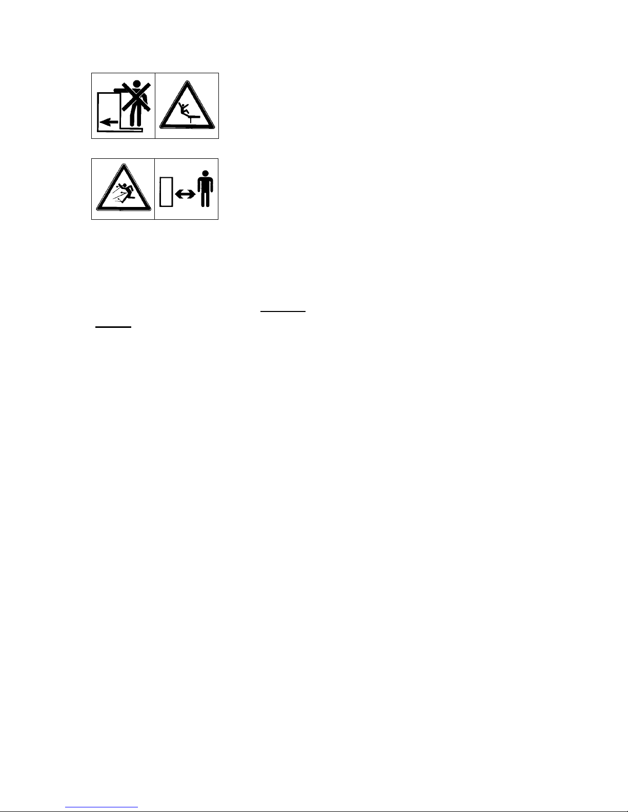
♦ Never leave the spreader running unattended.
It is illegal and dangerous to carry passengers when using
or transporting the spreader.
Attention: ! Danger from revolving discs and fast moving spreading material. Make sure no one is within the
spreading zone around the spreader before engaging
the PTO shaft/spreading discs!
♦ Before leaving the tractor seat, lower the spreader on to the ground, switch the
tractor off and remove the ignition key. With single acting hydraulic shutter controls, switch off the hydraulic hose shut-off valves.
♦ Parking the fertilizer spreader without
being attached to the tractor : only with an
empty hopper and on firm, level ground.
♦ Never allow anyone to enter the space between tractor and spreader without first
making sure that the tractor is prevented from moving by means of a parking brake
and/or wheel chocks.
♦ It is absolutely forbidden to remain between tractor and fertilizer spreader during
operation
♦ Before attaching or removing the spreader from the tractor 3-point linkage, make
sure that the control valve is positioned so that inadvertent lowering or raising of
the linkage is impossible.
♦ It is recommended that the condition of the spreader is checked by a recognised
dealer at the end of every season. Especially disc vanes and fixings.
♦ In the event of a failure during operation, switch off the spreader immediately.
Stop engine and remove the ignition key before checking and repairing the damage.
♦ PTO shaft and shaft protection damage must be repaired immediately before using
the spreader. WARNING: Power driven parts : this is a danger zone which can
cut or crush.
♦ Ill advised choice or use of fertilizer or other spreading material can cause serious
damage to people, animals, plants and the environment. Choose the correct material for your application. Handle with car and carefully follow the manufacturer's
instructions.
Page 7

7
Warning
Maximum attachment height of the fertiliser spreader!
Danger of injury by unintentional contact
with the spreading discs.
As protection against unintentional contact with the discs, the maximum attachment height of 1500 mm from the un-
derside of the guardrail to ground level must not be exceeded.
If this attachment height is insufficient
when in normal spreading mode, the late
top dressing mode position (attachment
height 0/ 6) should be used.
Essential safety instructions for the hydraulic system
♦ Hydraulic circuits contain oil under high pressure.
♦ Mark all hydraulic connections between tractor and implement at both coupling
sockets and plugs in order to avoid incorrect connection.
♦ Follow correct connecting instructions of hydraulic cylinder and motors. Inter-
changed hoses could cause the opposite effect to that expected.
♦ When connecting the hoses to the tractor, ensure that the hydraulic pressure in
both tractor and spreader has been relieved.
♦ Use suitable protection when locating leaks (safety goggles, gloves, etc.) in order
to avoid injury. Hydraulic fluid escaping under high pressure can penetrate the
skin and cause serious injuries! In case of injury, immediately consult a doctor, as
there is serious risk of infection.
♦ Before working on the hydraulic system, lower the fertilizer spreader on to the
ground, relieve the system pressure, switch off the engine and remove the ignition
key.
♦ Prior to coupling or uncoupling fittings, carefully clean all hydraulic connections.
♦ Operational time limit of a hydraulic hose line is six years from the date of manu-
facture. The manufacturing date of a hose is indicated in month and year on the
hose armature.
♦ The useful life of an undamaged hose should be limited to six years, including a
possible maximum two-year stocking period.
♦ Even when carefully stored and correctly used, hoses and hose connections un-
dergo natural aging. Therefore, their stocking and operational periods should not
be exceeded.
♦ Replacement hoses must meet the technical specifications quoted by the spreader
manufacturer.
Ground
Page 8
8
Warning and instruction decals
Warning and instruction decals give important information to operate the fertilizer
spreader without danger.
♦ Replace any decals that are missing or illegible.
♦ Further decals are available from the spare parts department of your dealer or di-
rect from the factory.
♦ Before placing new decals on the fertilizer spreader, remove all dust, dirt and
grease and thoroughly dry the area where the decal is placed.
♦ Correct decals must be placed on any replacements fitted to the machine during
maintenance or repair work.
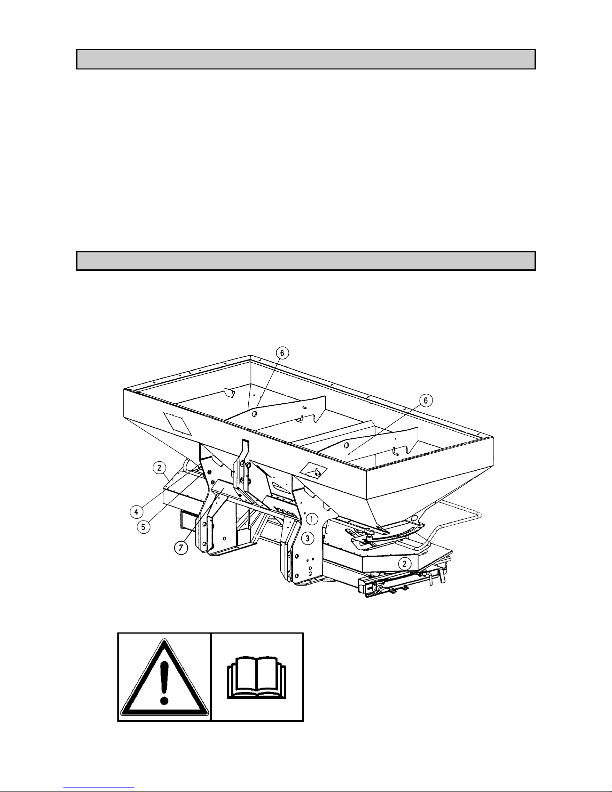
Warning and instruction decals on the fertilizer spreader
The fertilizer spreader carries the following warning and instruction decals which give important information for your safety and the safety of others. They also contain
information on correct operation. The text by each diagram explains the message that
the decal is giving.
c
Before starting the machine, read the
Operators Manual and safety instructions carefully.
Page 9

9
d
Danger from revolving discs and fast
moving spreading material. Make sure
no one is within the spreading zone before switching on the PTO
drive/spreading discs !
e
Maximum payload.
f
Machine No.
(Stamped on frame)
g
(Serial number plate)
h
(PTO speed)
i
(Hooking point when loading
e.g. with a crane.)
It is illegal and dangerous to carry any passenger on the fertiliser
spreader
Page 10

10
1. Machine specifications
Manufacturer
RAUCH Landmaschinenfabrik GmbH
Landstraße 14 Postfach 1162
D-76547 Sinzheim D-76545 Sinzheim
1.1 Technical specifications AXERA M range
Technical
Specifications
AXERA M
Capacity
approx. l 1100
Payload
max. kg 3500
Filling height
approx. cm 99
Filling width
approx. cm 240
Hopper size
approx. cm 250x115
Weight
approx. kg 430
Working width
m 12 - 42 m depending on fertilizer type and vanes
Noise level
70 db (A) (Depending on fertilizer type and application rate)
Empty weight data is giv en on the fertiliser spreader serial number plate
The weight of the fertiliser spreader (mass) when empty varies according to the equipment fitted.
The weight indicated on the serial number plate applies to the most commonly used specification. It can, however, be higher or lower.
Type / combination
Capacity
(+ litres)
Max. extension
size (cm)
Filling height
(+ cm)
Description Extension
weight (kg)
B 413 + 400 l 250x115 + 0 3- sided 25
B 713 + 700 l 250x115 + 10 3- sided 50
B 910 + 900 l 250x115 + 30 4- sided 50
B 1210 + 1200 l 250x115 + 42 4- sided 70
B 910 + B 413 + 1300 l 250x115 + 30 4+3- sided 75
B 910 + B 713 + 1600 l 250x115 + 40 4+3- sided 100
B 910 + B 910 + 1800 l 250x115 + 60 4+4- sided 100
B 1210 + B 713 + 1900 l 250x115 + 52 4+3- sided 120
B 1210 + B 910 + 2100 l 250x115 + 72 4+4- sided 120
GLB 903 + 900 l 280x115 + 15 3- sided 60
GLB 1000 + 1000 l 280x115 + 30 4- sided 65
GLB 1400 + 1400 l 280x115 + 43 4- sided 80
GLB 1000 + GL 700 + 1700 l 280x115 + 52 4+4- sided 110
GLB 1400 + GL 700 + 2100 l 280x115 + 65 4+4- sided 125
ATTENTION
Page 11

11
1.2 Taking delivery of the fertilizer spreader
When the fertilizer spreader is delivered, please check that it is complete.
The following items are included as standard equipment:
; Calibration kit (slide rule calculator)
; Top and bottom 3-point linkage pins
; Set of spreading discs (according to choice)
; PTO shaft (including PTO instruction book)
Also carefully check all ordered optional equipment.
Attention : Check all nuts and bolts and other fixings for tightness, especially those of the spreading discs and spreading vanes.
Right-hand disc (R) and left-hand disc (L) must be correctly mounted on
their respective sides when viewing the machine in direction of travel.
Discs and vanes are indicated with (R) or (L).
Claims can only be accepted if notified at time of delivery. Ask the haulier to acknowledge any transport damage. In case of doubt, contact your dealer or the factory
direct.
Page 12

12
2. Preparation of the fertilizer spreader
Take special care when attaching/detaching the fertilizer spreader
to/from the tractor.
2.1 Attaching to the tractor
The fertilizer spreader AXERA M can be attached to Cat.II tractor linkages. Attachment to Cat.III tractor linkages is only possible using Cat.II geometry and placing reduction sleeves over upper and lower linkage pins. A second lower link connection is provided as standard and allows a higher attachment height to the tractor
of approx. 140mm. The upper and lower pins must be secured in place with the
linchpins attached to the spreader.
For correct horizontal spreading of fertilizer, the fertilizer spreader must be attached
as per dimensions given in the spreading charts.
Pay attention that the spreader is mounted at right angles to the direction of travel, is
perfectly horizontal and that the 3-point frame is correctly restrained from sideways
movement to avoid the unit swinging from side to side during operation.
Important: If the lower link pins are in the upper connection point then the top
link pin must also be placed in its upper connection point, to avoid poor load distribution between upper and lower links.
2.2 Parking the fertilizer spreader
The spreader can be parked on the frame, support rollers or parking stand (support
rollers & parking stand are optional equipment).
When parking the spreader pay attention to the following :
♦ When operating the external tractor 3-point lift control lever, do not stand between
the tractor and the spreader.
♦ Before uncoupling the spreader from the tractor make sure that all weight from the
upper and lower linkage coupling points is relieved.
♦ Only park the spreader when the hopper is empty and on a firm level surface.
♦ After disconnecting PTO shaft and hydraulic hoses from the tractor, place them in
the holders provided on the spreader.
Page 13
13
2.3 Fitting the Tele-Space pto shaft (spreader side)
Only pto shafts supplied or recommended by the manufacturer should be used. The
fertiliser spreader is equipped with a pto shaft that corresponds to the implement's
technical characteristics and power requirements. It should not be replaced with
shafts with other specifications.
When first attaching the spreader to the tractor, the length of the shaft must be
matched and, if necessary, shortened to fit the tractor correctly.
Read the pto manufacturer's operator's manual carefully, taking special note of the
instructions concerning the shortening of the shaft. This operator's manual can be
found attached to the pto shaft.
If the pto shaft is too long, both pto drive and the spreader may be damaged when the
unit is raised.
The Tele-space pto shaft allows additional free room for easy coupling of the fertiliser spreader to the tractor.
DANGER
Fitting and removing the pto shaft (fertiliser spreader side)
Injury or death hazard due to rotating shaft.
• Before fitting or removing the pto shaft, make sure that the cou-
pled spreader is secured by support blocks to avoid unintentional
lowering and that the tractor is choked to avoid unintentional
creeping.
• Before fitting or removing the pto shaft, make sure that the pto
drive is disengaged, the tractor engine is switched off and the ignition key is removed!
• Always respect correct fitting and securing of the pto shaft. The end marked with
a tractor symbol must be fitted on the tractor side.
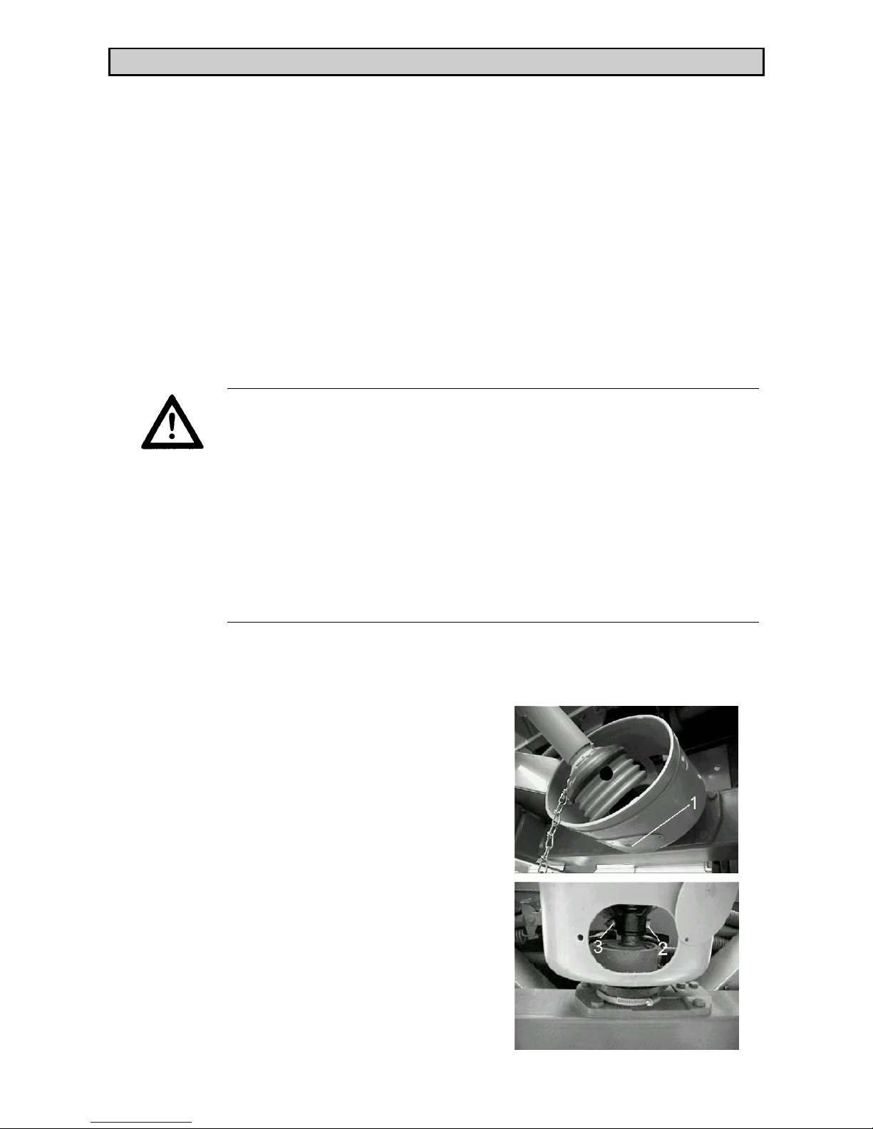
Remove the cover (1) from the bell protector
guard.
Fit the pto shaft onto the drive stub and secure in
place with the hexagon nut and bolt (2) and (3).
Page 14

14
Refit the cover (1) into its original place.
• Make sure that pto shafts, protector tube and end gaiter, as well as extension gai-
ters on the fertiliser spreader side, are correctly in place and in good condition!
• Do not use the safety chain to support the shaft when not in use.
• Before engaging the pto drive, make sure that the correct tractor pto speed is se-
lected to match the implement.
• When detaching the pto drive shaft, place in the holder provided on the fertiliser
spreader.
IMPORTANT
Drive shaft damage when engaging the pto drive
The pto drive shaft and the agitator drive can suffer damage if the
pto drive is engaged at high tractor engine speeds.
• Engage the pto drive at lower tractor engine speeds to avoid
sudden overload to the drive shaft and agitator drive.
• With abrupt engaging on hydraulic tractor pto drives, it is rec-
ommended that a pto incorporating a friction clutch is used.
Additional information for the fitting of pto shafts equipped with a friction
clutch (optional equipment).
WARNING
Friction clutch injury hazard
Pto drive shafts with friction clutches not conforming to recognised
standards can cause serious injury.
• The friction clutch must always be installed on the spreader si-
de.
• For safety reasons an additional extension guard must be fitted
to the spreader side when using a pto drive shaft equipped with
a friction clutch.
• Should a pto shaft with friction clutch be fitted after the ma-
chine has been delivered, the extension guard included with the
shaft must be fitted onto the spreader.
• It is recommended that the friction clutch be checked by a pro-
fessional workshop for correct functioning at the end of each
season.
Page 15

15
ASSEMBLY
• Fit the friction clutch extension guard to the spreader side.
• Slide the friction clutch end of the pto shaft onto the spreader
and bolt in place.
ATTENTION
Checking the friction clutch locking bolt for correct tightness
• The locking bolt should be checked regularly for tightness!
• Read the manufacturer's additional maintenance instructions
delivered with the friction clutch!
Page 16

16
2.4 Hydraulic control connection
Each shutter control mechanism is separately operated by two individual hydraulic
cylinders. After disconnecting the fertilizer spreader from the tractor, the dust caps
should be refitted in the hydraulic connections and, to avoid dirt contamination, the
hydraulic hoses must be placed in the holders provided on the spreader.
Important: Before every operation, check to ensure that both open/close shutter slides fully open and fully close.
2.4.1 Single acting two cylinder hydraulic shutter control
Oil pressure closes - Spring pressure opens
Tractors must be equipped with two hydraulic valves.
With optional extra double acting equipped units only one one control valve is
needed.
Prior to long transport journeys, or when filling, the hydraulic hose shut-off valves
must be closed, thus preventing subsequent opening of the shutter slides, should oil
inadvertently escape through the control valves.
By closing either the left- or the right-hand open/close shutter slide, the unit can be
operated to spread to one side only, thus avoiding double spreading or overspreading
in narrow field areas or on field edges and neighbouring fields.
If the empty spreader is uncoupled from the tractor, the open/close shutter slides
must be left open so that spring tension is not weakened.
2.4.2 Double acting two cylinder hydraulic shutter control
Oil pressure closes and opens
Tractors must be equipped with two hydraulic valves. By closing either the left- or
right-hand open/close shutter slides, the unit can be operated to spread to one side
only, thus avoiding double spreading or overspreading in narrow field areas or on
field edges and neighbouring fields.
Page 17

17
2.5 Fitting and removing the spreading discs
Depending on the fertilizer type and working width, different spreading discs can be
used. Spreading disc type is listed in the spreading charts. To simplify changing the
spreading discs it is recommended to slide the movable gearbox to the rear and lock
in place (see Photo 1). Using a screwdriver or ∅ 8 mm round bar, loosen the syn-
thetic disc hub nuts (Photo 1, No. 1) and remove spreading discs.
Only fit and remove spreading discs when the PTO and tractor engine
are switched off and the ignition key has been removed.
Spreading discs are fast moving parts, therefore carry out any work with
great care and attention.
Replace any defective synthetic disc hub nuts (threads, splits, fractures)
immediately.
Photo 1
Note: When fitting the spreading discs on to the disc hub, make sure not to invert
the right-hand spreading disc (R) with the left-hand spreading disc (L)!
The right-hand disc (R) and left-hand disc (L) must be placed carefully over their
corresponding drive hubs when viewing in the direction of travel.
Centre the spreading disc on to the disc hub, making sure it is lying correctly.
Discs and vanes are indicated with (R) or (L).
Page 18

18
♦ Make sure the synthetic disc hub nuts are correctly fitted (not cross-threaded)
(Photo 2; No.1).
♦ Tighten the synthetic disc hub nuts (Photo 2; No.1) by hand.
♦ Turn the spreading discs by hand to make sure discs and vanes (Photo 2; No.2)
turn freely without fouling the metering output tracts (Photo 2; No.3).
Photo 2
Important: After the first hour of operation, check that the synthetic disc hub nuts
(Photo 2; No.1) are firmly seated.
Page 19

19
3. Adjusting the spreader
3.1 Spreading charts
Values provided in the spreading charts are derived from practical tests in the manufacturer's purpose built fertilizer spreader research centre. Settings are obtained using
fertilizer in perfect condition from each respective manufacturer.
Note: The mounting height is always measured from the top of the crop to the lo-
wer edge of the frame.
Mount the fertilizer spreader on to the tractor in accordance with the instructions and
measurements given in the spreading charts.
We would particularly emphasize that physical characteristics of fertilizers can vary,
even within the same type and brand, due to differences in size of granules, density,
surface texture, specific weight and quality of granules, etc.
These variations can influence spreading characteristics quite markedly, which results in differences in the fertilizer application rates as well as changes in spread patterns predicted in the spreading charts, therefore, making it necessary to recalibrate
the fertilizer spreader.
The data provided in the spreading charts can only be used as a guideline. To ensure
greater accuracy, the unit should be recalibrated for application rate and spread pattern every time fertilizer is changed, even when using different bags of the same fertilizer.
We suggest the use of only quality fertilizer from well-known suppliers, preferably
those fertilizers listed in the spreading charts. If you need to use fertilizers not listed,
please contact us.
Note: Spreading of Urea: This highly concentrated nitrogen fertilizer has a wide
variation of quality and particle sizes, due to the great number of importers handling this product. It is therefore essential to recalibrate the unit every time this
fertilizer is used. Also note that Urea is very susceptible to wind variations.
Pay special attention when setting the spreader. Even a very small error in setting can
result in a large change in spreading pattern.
We must stress that no liability can be accepted for consequential losses or damages
due to spreading errors.
Before adjusting, lubricating, cleaning or carrying out any operation
on the machine, disengage PTO drive, switch off the tractor engine,
wait until all moving parts have come to a stop and remove the ignition key before leaving the tractor.
Page 20

20
3.2 Setting the application rate
There are two shutter slides per hopper outlet. The open/close shutter slides (Photo 3,
No.5) only move hydraulically to a fully opened or a fully closed position.
Photo 3
The hand operated metering slides (Photo 4, No.6) control the application rate with
the aid of a fine graded flow rate quandrant (Photo 4, No.7) and indicator (Photo 4,
No.8). When the application rate is selected in accordance with the spreading
charts/calibration test, position the metering slides (Photo 4, No.6) in the same place
on both sides by firmly locking the handlock nut (Photo 4, No.9) in place.
Photo 4
Page 21

21
3.3 Adjusting the fertilizer output point
The point at which the fertilizer drops on to the discs, the output point, is adjusted
by using the scales (Photo 5, No.10) on both sides of the spreader and the handlock
nuts (Photo 5, No.9). Photo 5 shows the output point adjusted to position 7. Altering
the output point determines the working width and allows adaptability to various fertilizers. Adjusting in the direction of smaller
numbers causes early ejection of fertilizer, thereby directing more material directly behind the spreader producing a corresponding spread pattern for smaller working widths
. Adjusting in the direction of
bigger
numbers causes later ejection of fertilizer, thereby directing material outwards into the overlap zones, producing a corresponding spread pattern for larger
working widths.
Photo 5
Important: In a new condition, the surface of the throwing vanes is not totally
smooth. For this reason it is recommended that during the first hopper load the output point is moved an extra 0.5 towards the smaller numbers
(e.g. from OP8 to
0P7.5). After the first load has been used up in both hoppers, the output point should
be readjusted back to the position indicated in the spreading charts, or that obtained
during calibration checks.
Page 22

22
3.4 Adjustment as per spreading charts (normal spreading / boundary
spreading during normal spreading)
Output point, disc type, mounting height and PTO speed must be adjusted as per the
spreading charts, according to the fertilizer used, desired working width and the type
of spreading operation to be adopted.
Normal spreading
Example: from spreading charts
Chosen fertilizer type:
NPK BASF
Desired application rate:
509 kg / ha
Chosen working width:
21 m
Desired forward speed:
10 km/h
The spreader must be adjusted to the following settings:
Disc type:
D4 M VXR
PTO speed:
540 rpm
Mounting height:
50/50 [cm] measured
from top of standing crop.
Output point:
8.5 (left and right)
Metering slide position:
290
Boundary spreading during normal
spreading
Example. from spreading charts
Chosen fertilizer type:
NPK BASF
Desired application rate:
509 kg / ha
Chosen working width:
21 m
Desired forward speed :
10 km/h
The spreader must be adjusted to the following settings:
Disc type on left-hand side (viewed in driving direction) : D4 M VXR
Disc type on right-hand side (viewed in
driving direction): DG 69. Here both vanes
must be set in their normal position (one
vane in D setting and the other in E).
PTO speed:
540 rpm
Mounting height:
50/50 [cm] measured
from top of standing crop.
Output point:
8.5 (left and right).
With left- or right-hand boundary spreading the output point can be individually set
according to working width and fertilizer
type (see spreading charts).
Metering slide position:
290
Page 23

23
3.5 Adjustment as per spreading charts (late top dressing / boundary
spreading during late top dressing)
Output point, disc type, mounting height and PTO speed must be adjusted as per the
spreading charts according to the fertilizer used, desired working widths and the type
of spreading operation to be adopted.
Late top dressing
Example.:
Chosen fertilizer type : e.g. KAS
Desired working width:
21 m
Desired application rate:
211 kg/ha
Desired forward speed.:
10 km/h
The spreader must be adjusted to the following settings:
Disc type:
D4 M VXR
PTO speed:
540 rpm
Mounting height:
0/6 [cm] measured from
top of standing crop.
Output point:
8.5 (left and right)
Metering slide position:
120
Boundary spreading during late top
dressing
Example:
Chosen fertilizer type : e.g. KAS
Desired working width:
21 m
Desired application rate:
211 kg/ha
Desired forward speed.:
10 km/h
The spreader must be adjusted to the following settings:
Disc type on left-hand side
(viewed in direction of travel): D4 M VXR
Disc type on right-hand side (viewed in direction of travel): DG 69. Here both vanes
must be set in their normal position (i.e. one
vane in D setting and the other in E).
PTO speed:
540 rpm
Mounting height:
0/6 [cm] measured from
top of standing crop.
Output point:
8.5 (left and right).
With left- or right-hand boundary spreading
the output point can be individually set according to working width and fertilizer type
(see spreading charts)..
Metering slide position:
120
Page 24

24
3.6 Boundary spreading with boundary spreading discs DG68 - 72 (Optional
Equipment)
Rauch offers boundary spreading discs DG68 - 72 as optional equipment. When
mounted on to the right-hand spreading side the boundary spreading disc creates a
steeply falling spread pattern. Over application of fertilizer at field edges or under
application within the field is reduced to a minimum. Due to the strong influence exerted by the fertilizer in spread patterns, the same spreading accuracy cannot always
be achieved as when operating with normal spreading discs.
Boundary spreading discs are equipped with two adjustable vanes. The vanes must
be positioned as per information in the spreading charts to achieve desired working
widths when using fertilizer indicated.
Release the vane lock studs under the disc and adjust the vanes into one of the five
positions (C - G) in accordance with the information in the spreading charts, making
sure to retighten after correctly positioning.
3.7 Boundary spreading limiter (GSE 5) (Optional Equipment)
Using the adjustable boundary spreading limiter, it is possible to adjust boundary
spreading limit between 0.75 and 3m. Settings vary according to fertilizer type being
spread. If desired, the boundary spreading limiter can be equipped with an electronic
remote control. Separate fitting instructions are supplied with the boundary spreading limiter.
Page 25

25
3.8 Setting disc vanes for fertilizers not listed in spreading charts
A practical test kit, supplied as an optional, extra offers a simple and quick method
of checking the spread patterns. By using this kit it is possible to obtain settings for
fertilizers not listed in the spreading charts.
♦ Choose a fertilizer from the spreading charts that has the nearest characteristics to
the one that needs to be used and adjust the spreader to these settings.
♦ Test on a dry calm day so that weather conditions do not influence the results.
♦ A test area should be chosen which is horizontal in both directions and is large e-
nough to achieve 3 tramlines over a length of 60 to 70 m.
♦ Carry out the test, either on freshly mown grass or in a field with low vegetation
(max. 10cm), and make sure that the 3 tramlines run parallel to each other. When
carrying out a test without pre-set tramlines the tracks must be measured using a
tape measure and marked with suitable post markers.
♦ The three tracks must not contain any notable bumps or hollows as these could
cause a shift in the spread pattern.
♦ Place two collecting containers one behind the other (1m apart) as per the follow-
ing sketch. One pair in each overlap zone and one pair in the centre of the middle
tramline.
1/2 AB
Working width (AB)
1/2 AB
123
Page 26

26
Make sure individual containers are level. Containers set at an angle can lead to measuring errors.
♦ Set the spreader at the same height on the left- and right-hand side in accordance
with the information in the spreading charts, paying attention that the mounting
height is taken from the top edge of the collecting containers.
♦ Before testing, check the functioning and condition of the spreading elements
(discs, vanes, metering slides).
♦ Carry out a calibration check (see under "calibration check") possibly resetting the
left- and right-hand metering slides, locking in place with the handlock nuts. Make
first test using this aperture setting.
If it is felt that the fertilizer collected in the trays is not enough for a clear analysis
merely travel over the trays twice. Do not change metering slide aperture setting.
♦ Select only a tractor speed between 3 and 4 km/h so as to keep tractor and spreader
as steady as possible. Keep the metering slides to the same setting. It is irrelevant
to the test that the actual application rate is higher, as this is only a result of the
slower tractor speed for test purposes. Keep speed of tractor constant throughout
the test.
♦ Spread along the tramlines one to three, one after the other. Open the open/close
shutter slides approx. 10m before reaching the collection containers and close approx. 30m after passing them. If collected volume is insufficient, repeat all three
passes.
♦ Pool the contents of each pair of containers and pour into the respective measuring
tubes i.e. left-hand pair in left-hand tube, middle pair in middle tube, right-hand
pair in right-hand tube. The evenness of spread pattern can now be judged from
the level in each tube.
Page 27

27
Following results are possible:
A
Same quantity in all three tubes
(allowed tolerance ±1 mark)
The spread pattern is acceptable.
B
Lop-sided spread pattern.
Unacceptable.
C
Too much fertilizer in the overlap zone.
Unacceptable.
D
Too little fertilizer in the overlap zone.
Unacceptable.
Hints for correcting the spread pattern
If results are obtained as shown in example B, check that both right- and left-hand
metering slides open exactly equally. Check that the output points on each disc are
set exactly equally. Check that the spreader is set exactly horizontally. Check that the
tramline widths are equally spaced and parallel, even a slight error with one tramline
being closer to another will cause a poor result. Has there been a cross wind during
the test run ?
If the results are obtained as shown in example C, an earlier output point should be
selected so that the fertilizer in the overlap zone is reduced.
(Example : adjust from OP 5 to OP 4).
If results are obtained as shown in example D, a later output point should be selected
so that fertilizer in the overlap zone is increased.
(Example.: Adjust from OP 8 to OP 9).
Page 28
28
4. Calibration check
4.1 Calculating the mean application rate
To ensure accurate application rates we recommend that a new calibration check is
carried out each time a new type or different batch of fertilizer is used. Calibration
must be done when the machine is stationary with the PTO revolving at 540 rpm, or
according to spreading charts, depending on fertilizer, or when driving over a test
length.
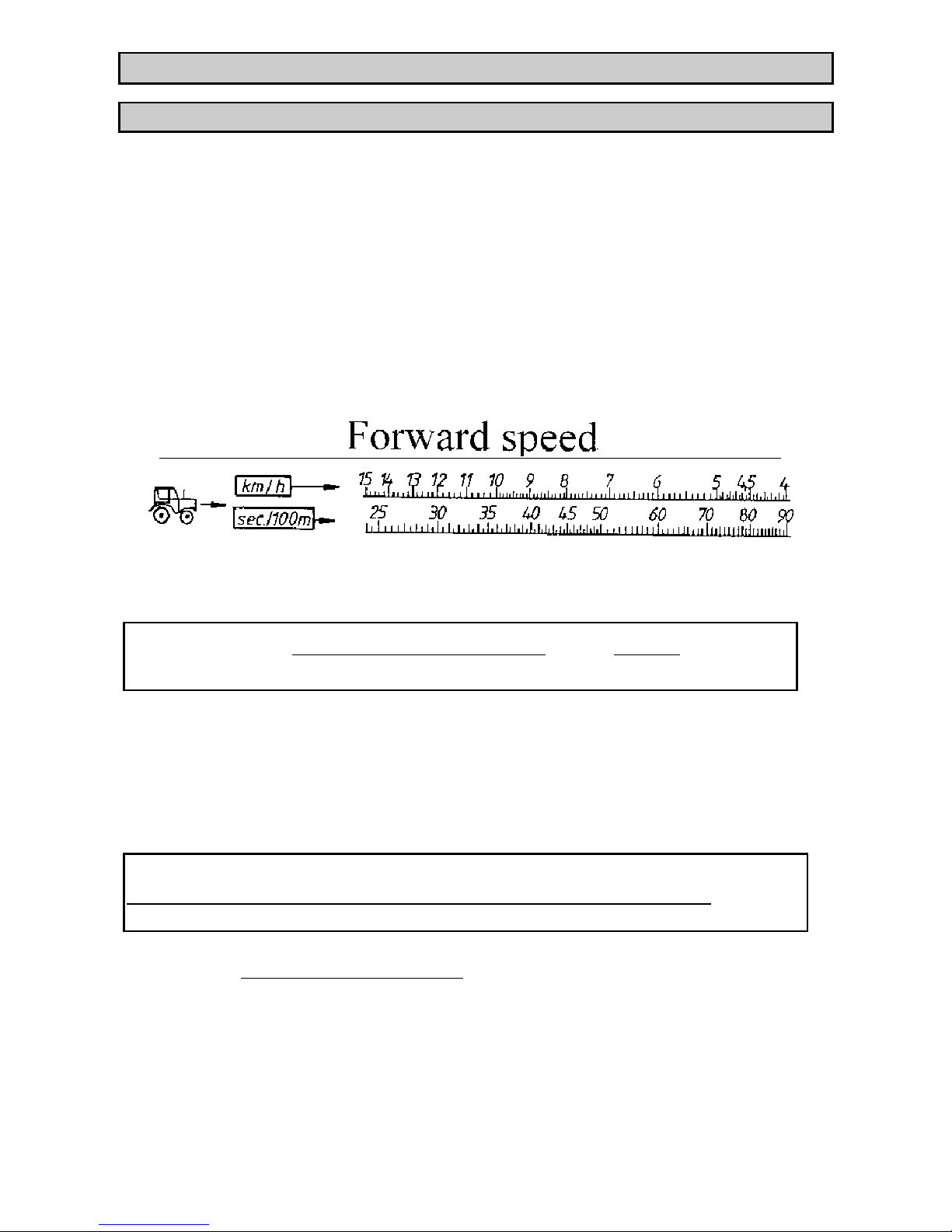
Calculation of precise tractor forward speed:
For more precise measurement of tractor forward speed to that given by the tractor
meter, drive a measured 100m on a field with the hopper half full and measure the
time taken.
Tractor speeds outside the scale can be calculated using the following formular :
Tractor speed =
360
measured time for 100m
e.g.
360
36 secs
=
10 km/h
Determination of the required mean output per minute:
The calibration check is only carried out with one shutter outlet. However, the fertilizer quantity required is calculated for both shutter outlets i.e. total working width,
therefore the calculated quantity should be halved for calibration purposes.
Tractor speed (km/h) x working width (m) x application rate (kg/ha)
600
= kg/min
Example:
8 km/h x 18 m x 300 kg/ha
600
= 72 kg/min
Therefore, 36kg of fertilizer must flow through one shutter outlet in 60 secs. In order to determine the correct metering slide setting, several attempts may be required.
(Use values provided in the spreading charts as a guideline).
Page 29

29
Calculation using the calibration slide rule
Position the 300kg/ha figure below the 18m figure on the working width scale and
then read off the value for kg/min above 8km/h on the speed scale; 72kg/min will be
the required mean fertilizer quantity for both shutter outlets.
Output figures for a selection of application rates and tractor speeds are already provided in the spreading charts.
4.2 Carrying out the calibration check
When working with the fertilizer spreader in the raised position, make
sure that it is safely supported on blocks under the frame. (Accident
danger.)
♦ Turn the disc by hand on the side chosen to undertake the calibration check until
the disc vanes are at right angles to the direction of travel.
♦ Slide the gearbox rearwards and remove both discs.
♦ Adjust metering slide according to information given in the spreading charts and
lock securely in place using the handlock nut.
♦ Place a bucket under the shutter outlet.
♦ Engage PTO shaft and set speed to 540 rpm.
♦ Open the corresponding open/close shutter slide.
♦ An output of kg/min must be obtained. Preferably allow a full 60 seconds during
the test but as this may involve a greater quantity of fertilizer than the bucket will
hold a time of 20 to 30 seconds can be used. However, remember to multiply the
result accordingly to obtain a theoretical minute.
♦ Weigh the amount collected, remembering to subtract the weight of the bucket.
♦ If the actual weight differs from the guideline figures given in the spreading
charts, alter the position of the metering slide and repeat the calibration check.
Note: The metering slide scale is laid out proportionally, which allows the metering
slide to be altered to compensate any difference obtained in the application rate.
e.g.:
If 10% too little fertilizer is collected when the metering slide is in position
400, select a new position of 400+10% = 440, and lock securely in place.
You may need to repeat the process several times before the correct application rate is achieved. Remember, actual weight measured must be half of the
application rate required as only one half of the total width is used for the
calibration check.
Page 30

30
♦ Set the other spreading side using the same metering slide position obtained, and
lock securely in place.
♦ After completing the calibration check, refit both discs.
♦ The right-hand disc (R) and left-hand disc (L) must be replaced carefully over
their corresponding drive hubs when viewing in the direction of travel. Make sure
both discs lie correctly on their drive hubs. Discs and vanes are indicated with (R)
and (L).
♦ Make sure the synthetic disc hub nuts are correctly fitted (not cross-threaded).
♦ Tighten synthetic disc hub nuts by hand.
♦ Reposition gearbox to the desired output point on both sides.
♦ Turn the spreading disc by hand to make sure discs and vanes turn freely without
fouling.
5. Removing unused fertilizer
To keep the spreader in good condition we recommend that all unused fertilizer is
removed immediately after field operations are completed. Follow instructions under
section 4.2 ( carrying out calibration check) to drain hopper. Use both left- and righthand shutter outlets. Any leftovers can be removed from inside the hopper with a
brush and pan.
6. Cleaning
To keep the spreader in good condition we recommend the unit be thoroughly cleaned with a low pressure water jet immediately after field operations are completed.
To simplify cleaning the hopper sieve can be removed.
When cleaning, make sure that the shutter control and shutter flow tracts are cleaned
from underneath.
Only wash in suitable areas specifically designed to collect and remove environmen-
tally damaging elements such as oil and fertilizer, without endangering the surrounding environment.
When washing with pressure washers, never direct the jet directly into any electrical
elements, on to warning decals, exposed hydraulic machine parts or exposed bearings.
After drying off the spreader we recommend that it is treated with environmentally
acceptable biodegradable anti-corrosion liquid or spray. It is especially important to
treat the vanes.
Page 31

31
7. Service
When servicing the spreader in the raised position, make sure that suitable chock supports are placed under the frame to support its weight.
Only spare parts that correspond to the technical specification demanded by the implement manufacturer should be used. These specifications are only obtainable with
original spare parts.
Regularly check nuts and bolts for tightness and tighten up where necessary.
Wear parts:
Spreading blades, agitator, outlet
If these parts show perceivable wear and tear, deformations or holes they have to be
replaced, as these can result in irregular spreading patterns.
The life of wear parts depends among other things on the used spreading materials.
7.1 Servicing PTO shafts fitted with a slip clutch (optional equipment)
After a time, especially if the PTO has not been used, the clutch plates will tend to
stick together and will need to be freed. Consult the Walterscheid service manual to
follow correct procedure.
Important: An incorrect functioning slip clutch can cause damage to the gear train
in either the fertilizer spreader or the tractor.
8. Lubrication chart
♦ PTO shaft : lubricate as per Walterscheid instruction book.
♦ Gearbox : change oil every 1000 working hours, or at least every 4 years. The
gearbox is filled with 7.7 litres of oil.
The gearbox can be filled with oil corresponding to standards CLP 460 DIN 51517.
Some of these oils are listed below:
Aral: Degol BG 460
BP: Energol GR-XP 460
Castrol: Alpha SP 460
DEA Falcon CLP 460
Esso: Spartan EP 460
Fina: Giran 460
Mobil: Mobilgear 634
Shell: Omala Öl 460
Total: Carter EP 460
Texaco: Meropa 460
Important: These oils must not be mixed together. Always carry out complete oil changes.
Page 32

32
8.1 Gear oil (control and changing)
Under normal working conditions the geartrain is assured for the life of the unit.
However, when consistently using fertilizer with a high dust content as well as con-
tinual cleaning, an oil change is recommended once every five years.
The drain plug (dia. 6; fig. 9) is on the left-hand side of the gearbox. To drain the
box, the spreader should be raised on the other side by about 200 mm.
As if cannot be avoided that some oil remains in the box, when refilling the complete
capacity of 7 litres can be slightly.
To assure correct geartrain lubrication, the oil level must be correctly controlled.
The level is correct when oil just starts to flow out of the opened filling/oil level plug
(dia. 6; fig. 8) when the spreader is exactly horizontal.
8
9
photo 6
Note: Dispose of old oil in an environmentally correct way.
Page 33

33
9. Checking the balance of the metering slides
Before each season and regularly during the season, the metering slides should be
checked to ensure that they open simultaneously and evenly. This can be done by
placing the ∅ 28 mm lower link pins in both shutter apertures (Photo 7 shows a
lower link pin placed in a shutter aperture that, for better clarity, has not been installed in the hopper floor).
To correctly check the slide position, both pins must be held vertically from under
the floor.
When the slide position is correct, the application rate indication lever must read 56.
Photo 7
Attention: Metering and open/close shutter slides can cause crushing
and cutting injuries if attention is not paid during all balancing operations. Never activate the hydraulic open/close shutter slide while undertaking any adjustment and balancing operations (Injury and damage
danger!)
If the application rate indication lever does not read 56, release the quadrant scale by
unscrewing the three locking bolts (Photo 8, No.10) and slide the scale until the value 56 is achieved. Retighten the three bolts.
Page 34

34
Photo 8
10. Gearbox position control
♦ Remove the discs.
♦ The distance from the top of the hub to the underside of the hopper floor (Photo 9;
No.3) must be 11.8 cm.
♦ Replace the synthetic disc hub nut (Photo 9; No.1).
♦ Place the M6 x 70 bolt (Photo 9; No.2) (V) through the small hole in the hopper
floor (Photo 9; No.3)
♦ When in output point position 7, the bolt tip must align exactly with the middle
point of the synthetic disc hub nut (Photo 9; No.1).
Photo 9
Page 35

35
11. Valuable tips for precision spreading
We would particularly emphasize that physical characteristics of fertilizers can vary,
even within the same type and brand, due to differences in size of granules, density,
surface texture, specific weight and quality of granules, etc.
These variations can influence spreading characteristics quite markedly resulting in
differences in the fertilizer application rates as well as changes in spread patterns
predicted in the spreading charts.
The data provided in the spreading charts can only be used as a guideline. However,
through careful continued testing these values are more accurate than settings made
by rule of thumb.
We suggest the use of only quality fertilizer from well-known suppliers, preferably
those fertilizers listed in the spreading charts. If you need to use fertilizers not listed,
please contact us.
In spite of the careful manufacture of your spreader, even with correct usage we cannot completely rule out variations in output or total output failure. Such circumstances can be caused by the following :
♦ Varying consistency and flow characteristics of fertilizer or seed (e.g. variations of
particle sizes, coatings, density, shape, causticity).
♦ Lumpy moist fertilizer.
♦ Wind drift.
♦ Blockage or bridging (e.g. caused by foreign particles, bits of bag, moist fertilizer,
etc).
♦ Undulating fields.
♦ Wear on components (e.g. agitator, vanes, metering outlets).
♦ Defects arising from external influences.
♦ Lack of cleaning or prevention against corrosion.
♦ Incorrect input speed from the PTO or incorrect tractor speed.
♦ Not carrying out calibration check.
♦ Incorrect setting of fertilizer spreader.
♦ 3-point linkage not adequately restrained from side-to-side movement, or spreader
not exactly at 90° to direction of travel, or unit not exactly horizontal
Before each field operation, as well as during operation, check that the fertilizer
spreader is functioning correctly and that the correct application rate and spread pattern is being achieved at all times.
Spreading Urea:
This highly concentrated nitrogen fertilizer has a wide variation of quality and particle sizes, due to the great number of importers handling this product. It is, therefore,
essential to recalibrate the unit every time this fertilizer is used. Also note that Urea
is very susceptible to wind variations.
Pay special attention when setting the spreader. Even a very small error in setting can
result in a large change in spread pattern.
We must stress that no liability can be accepted for consequential losses or damages
due to spreading errors.
Note: Particularly hard fertilizer material such as Thomas potash and Kiserit will increase the wear rate of the disc vanes.
Page 36

36
12. Fault diagnosis
Uneven spread pattern
♦ Remove fertilizer build-up around spreading discs, disc vanes and shutter outlets.
♦ Check disc and disc vane positions correspond correctly with spreading charts.
♦ Make sure open/close shutter slide is fully open.
Too much fertilizer within tractor tracks
♦ Check disc vanes and shutter outlets. Replace any defective parts immediately.
♦ Fertilizer granules have a smoother surface than those tested for the spreading
charts. Check disc vane position.
♦ Check position of output point (see chapters 3.4 and 3.8)
Too much fertilizer in overlapping zones
♦ Fertilizer granules have a rougher surface than those tested for the calibration
charts. Check disc vane operation/position.
♦ PTO speed is higher than what the tractor tachometer indicates. Check rpm.
♦ Check position of output point (see chapters 3.4 and 3.8).
Spreading application higher on one side than the other
♦ Check that metering slides are opening equally.
Fertilizer flow to spreading discs is uneven
♦ Check agitator and replace if necessary.
♦ Fertilizer has formed a bridge over the shutter outlet.
Spreading discs are "fluttering"
♦ Check synthetic disc hub nut is correctly tightened into position.
Hopper empties unevenly even though both right- and left-hand sides have been
equally used
♦ Check that both metering slide positions are equal and that both open/close shutter
slides are fully open.
Hydraulic cylinder does not open
♦ Open/close shutter slide has too much resistance. Check shutter, levers and pivot
points are free and adequately lubricated.
Agitator does not function
♦ Increase tightening pressure of brake locking nuts. (U-form flat steel that half
encloses the agitator shaft, which is attached under the fertilizer spreader bolts.)
Page 37

37
13. Optional equipment
13.1 Hopper extension sets
The fertilizer spreader hopper capacity (basic unit 1100 litre capacity) can be in-
creased by adding an extension set, available in various sizes.
Notes on combination of extension sets:
❐ All hopper extensions with their description numbers finishing with a zero are 4-
sided extensions. Two 4-sided extensions can be fitted on top of one another.
❐ All hopper extensions with their description number finishing with a figure "3"
are 3-sided finishing extensions
❐ All hopper extensions with their description number beginning with "B" can be
fitted to the base hopper or onto the 4-sided "B" extensions B 910 and B 1210.
❐ Adaptor extension sets GLB 1000 and GLB 1400 can be fitted onto the base hop-
per. Only the GLB 1000 and GLB 1400 sets can be used as the base extension set
for the GL 700.
❐ Maximum filling width is 10 cm less than the maximum extension set width.
Type / combination
Capacity
(+ litres)
Max. extension
size (cm)
Filling height
(+ cm)
Description Extension
weight (kg)
B 413 + 400 l 250x115 + 0 3- sided 25
B 713 + 700 l 250x115 + 10 3- sided 50
B 910 + 900 l 250x115 + 30 4- sided 50
B 1210 + 1200 l 250x115 + 42 4- sided 70
B 910 + B 413 + 1300 l 250x115 + 30 4+3- sided 75
B 910 + B 713 + 1600 l 250x115 + 40 4+3- sided 100
B 910 + B 910 + 1800 l 250x115 + 60 4+4- sided 100
B 1210 + B 713 + 1900 l 250x115 + 52 4+3- sided 120
B 1210 + B 910 + 2100 l 250x115 + 72 4+4- sided 120
GLB 903 + 900 l 280x115 + 15 3- sided 60
GLB 1000 + 1000 l 280x115 + 30 4- sided 65
GLB 1400 + 1400 l 280x115 + 43 4- sided 80
GLB 1000 + GL 700 + 1700 l 280x115 + 52 4+4- sided 110
GLB 1400 + GL 700 + 2100 l 280x115 + 65 4+4- sided 125
Fitting instructions are supplied with each extension set.
Important: Maximum AXERA M payload is 3500 kg.
Page 38

38
Example: the specific weight of Thomaspotash = 1.35kg/l. As the maximum payload of the AXERA M Fertilizer Spreader is 3500kg, a total capacity of 2592,6 litres
of Thomaspotash should not be exceeded.
Max. capacity=
max. payload
spez. Weight of fertilizer
e.g:
3500 kg
1,35 kg/l
=
2592,6 Litres
13.2 Hopper cover (AP 10 / APE 10)
The hopper cover can be opened from the front or the back. Depending on extension
set used, a hopper cover extension (APE 10) is obligatory to fully cover the hopper.
Fitting instructions are supplied with each hopper cover / hopper cover extension.
13.3 Hopper cover (AP 11)
The hopper cover can be opened from the front or back. The back section is longer to
allow safer sealing with 3-sided hopper extension sets. Fitting instructions are supplied with each hopper extension.
13.4 Parking stand / support rollers
When the spreader is empty it can be easily parked using the support stand or support
rollers. By using the support rollers the empty spreader can be manoeuvred without
tractor help into its parking place. Support rollers and parking stand are supplied together with fitting instructions.
13.5 Lighting set BLW 11 (c/w warning shield and reflectors for rear visual se-
curity)
The unit must be equipped with a light and warning set for rear visual security which
conforms to the rules and traffic regulations of the country concerned. The lighting
set is supplied together with fitting instructions.
13.6 Lighting set BLW 12 (c/w warning shield and and positioning lights for
frontal visual security)
The unit must be equipped with a light and warning set for frontal visual security
which conforms to the rules and traffic regulations of the country concerned. The
lighting set is supplied together with fitting instructions.
Page 39

39
13.7 Boundary spreader discs DG 68 - DG 72
When mounted to the right-hand spreader side, the boundary spreader discs create a
steeply falling spread pattern. Over application of fertilizer at field edges or under
application within the field is reduced to a minimum. Due to the strong influence exerted by fertilizer on spread patterns, the same spreading accuracy cannot always be
achieved when operating with normal spreading discs.
DG 68: Boundary spread distance 6 - 8m
(right-hand side viewed in direction of travel)
DG 69: Boundary spread distance 9 - 10.5m
(right-hand side viewed in direction of travel)
DG 71: Boundary spread distance 12 - 14m
(right-hand side viewed in direction of travel)
DG 72: Boundary spread distance 15 - 18m
(right-hand side viewed in direction of travel)
13.8 Boundary spreading limiter (GSE 5)
Using the adjustable boundary spreading limiter, it is possible to adjust the boundary
spreading limit between 0.75m and 3m. Settings vary according to fertilizer type being spread. If desired, the boundary spreading limiter can be equipped with an electrical remote control. Separate fitting instructions are supplied with the boundary
spreading limiter.
13.9 Plus / Minus flow rate control (PMS 4 - N) / (PMS 5 - S)
The Plus/Minus flow rate control allows on-the-move adjustment in an infinitely
variable pre-set increase or decrease in application rate. The output can be changed
independently on either left- or right-hand sides. The operator control lever bracket
is attached within easy reach of the operator. Fitting instructions are supplied with
each Plug/Minus flow rate control.
13.10 Slip clutch
When overloaded, torque is reduced and progressively transmitted during clutch
slippage. Sudden torque peaks will be reduced. Slip clutches are supplied together
with a separate manual.
13.11 Double acting mechanism ZWE 1
Using the double acting mechanism, the fertilizer spreader can also be used on a tractor equipped with only one single acting control valve. Separate fitting instructions
are supplied with the double acting mechanism.
Page 40

LIMITED WARRANTY
KUHN S.A. of 4 Impasse des Fabriques, 67706 SAVERNE CEDEX, France (hereinafter called the
«Company») warrants, in accordance with the provisions below, to each original retail purchaser of
KUHN new equipment of its own manufacture, from an authorized KUHN dealer, that such equipment
is, at the time of delivery to such purchaser, free from defects in material and workmanship and that
such equipment will be warranted for a period of one year starting from the date the goods are delivered
to the end user and during this period up to a limit of 500 hours use, providing the machine is used and
serviced in accordance with the recommendations in the Operator’s Manual.
THESE CONDITIONS ARE SUBJECT TO THE FOLLOWING EXCEPTIONS :
1. Parts of machines which are not of our manufacture i.e. tyres, belts, P.T.O. shafts, clutches etc., are not
covered by this Limited Warranty but are subject to the warranty of the original manufacturer. Any claim
falling into this category will be taken up with the manufacturer concerned.
2. Warranty claims applying to these types of parts must be handled in the same way as if they were parts
manufactured by KUHN. However, compensation will be paid in accordance with the warranty agreement of the manufacturer concerned in as much as the latter justifies such a claim.
3. This Limited Warranty will be withdrawn if any equipment has been used for purposes other than for
which it was intended or if it has been misused, neglected or damaged by accident or let out on hire. Nor
can claims be accepted if parts other than those manufactured by us have been incorporated in any of
our equipment. Furthermore, the Company shall not be responsible for damage in transit or handling by
any common carrier and under no circumstances within or without the warranty period will the Company
be liable for damages for loss of use or damages resulting from delay or any consequential damage.
We cannot be held responsible for loss of earnings caused by a breakdown or for injuries either to the owner
or to a third party, nor can we be called upon to be responsible for labor charges, other than originally
agreed, incurred in the removal or replacements of components.
THE CUSTOMER WILL BE RESPONSIBLE FOR AND BEAR THE COSTS OF:
1. Normal maintenance such as greasing, maintenance of oil levels, minor adjustments, etc.
2. Transportation of any kind of any KUHN product to and from the place the warranty work is performed.
3. Dealer travel time to and from the machine or to deliver and return the machine from the workshop for
repair.
4. Dealer travelling costs.
Parts defined as normal wearing items are listed as follows and are not in any way covered under this
Limited Warranty :
V belts, discs, knives, wear plates, disc guards, tires, torque limiters, hydraulic hoses, pitman shafts, swath
sticks, blades, tines and tine holders.
KUHN Limited Warranty will not apply to any product which is altered or modified without the expressed
permission of the Company and/or repaired by anyone other than Authorized Service Distributors or
Authorized Service Dealers.
Page 41

LIMITED WARRANTY IS DEPENDENT UPON THE STRICT OBSERVANCE BY THE
PURCHASER OF THE FOLLOWING PROVISIONS :
- That this Limited Warranty shall not be assigned or transferred to anyone unless the Company’s consent in
writing has first been obtained.
- The warranty/product registration form has been correctly completed by dealer and purchaser with their
names and addresses, dated, signed and returned to the appropriate address as given on the warranty/
product registration form.
- The claim form sent to KUHN has been correctly completed stating:
* dealer’s name and address
* owner’s name and address
* type of machine
* machine serial number
* delivery date to buyer
* date of failure
* tractor make and type
* description of the failure and its cause
* quantity, reference number and name of the damaged parts
* reference number, quantity and date of the invoice for the replacement parts.
- The judgement of the Company in all cases of claims under this Limited Warranty shall be final and conclu-
sive and the purchaser agrees to accept its decisions on all questions as to defect and to the exchange of
any part or parts.
- That all safety instructions in the Operator’s Manual shall be followed and all safety guards regularly inspected
and replaced where necessary.
No warranty is given on second-hand products and none is to be implied. Persons dealing in the Company’s
products are in no way legal agents of the Company and have no right or authority to assume any obligation
on their behalf, express implied, or to bind them in any way.
KUHN S.A. reserves the right to incorporate any change in design in its products without obligation to make
such changes on units previously manufactured.
Moreover, because of the constant progress in technology, no guarantee is given to the descriptions of
equipment published in any document by the company.
DISCLAIMER OF FURTHER WARRANTY
There are no warranties, expressed or implied, except as set forth above. There is no
warranty of merchantability. There are no warranties which extend beyond the description
of the product contained herein. In no event shall the company be liable for indirect, special
or consequential damages (such as loss of anticipated profits) in connection with the retail
purchaser’s use of the product.
Page 42

- N O T E S -
Page 43

Page 44

Page 45

This machine complies with the safety requirements of the European machinery directive.
The Operator should respect all Health and Safety regulations as well as the Highway
Code. For your own safety, use only genuine KUHN spare parts. The manufacturer
disclaims all responsibilities due to incorrect use or non-compliance with the
recommendations given in this manual.
Page 46

Printed in France by KUHN
KUHN S.A. 4 Impasse des Fabriques F - 67706 SAVERNE CEDEX (FRANCE)
Tél. : + 33 (0) 3 88 01 81 00 - Fax : + 33 (0) 3 88 01 81 03
www.kuhnsa.com - E-mail : info@kuhnsa.com
Société Anonyme au Capital de 19 488 000 Euros
For your safety
and to get the best from your machine,
use only genuine KUHN parts
 Loading...