

Page 1
1
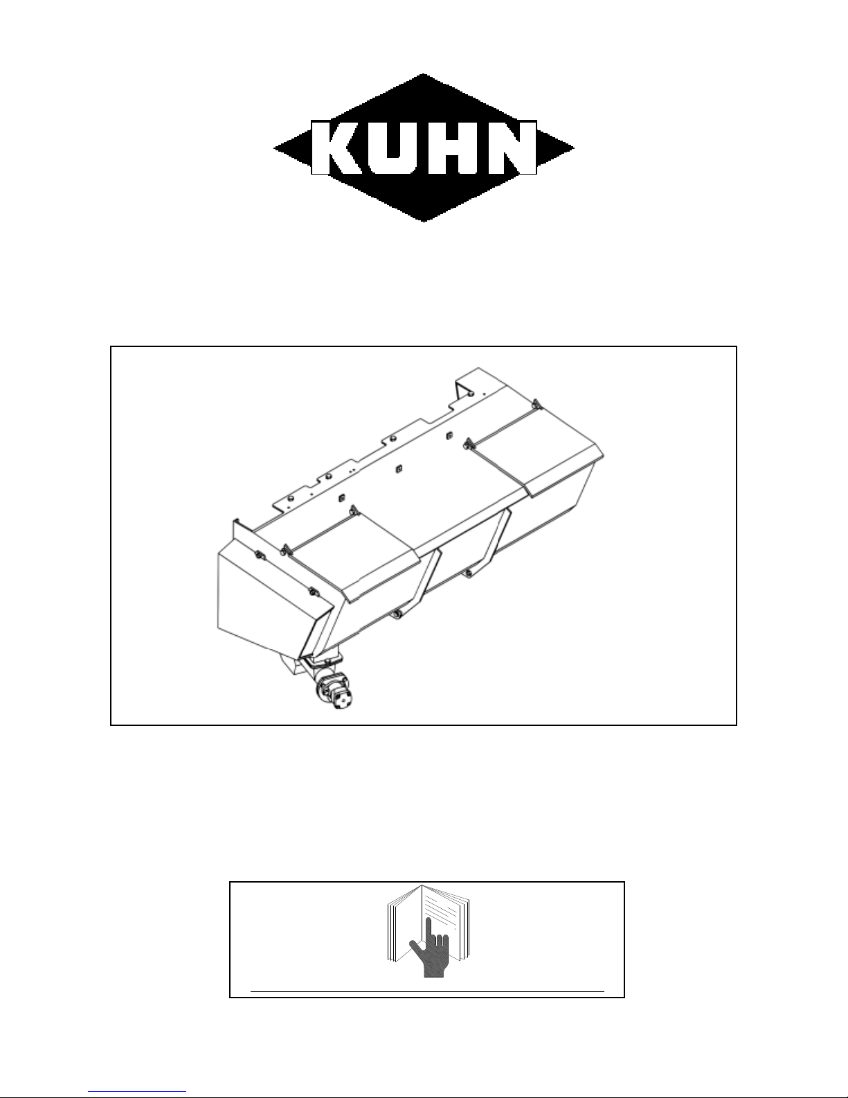
INSTRUCTIONS MANUAL
A7310032 0 05-00
OPTIONAL MIXING HOPPER FOR
ALTOR 4560 - 7560 - 8060
ATHENOR 7560 - 8060
PLEASE READ CAREFULL Y BEFORE USING THE MACHINE
Page 2

2
MESSAGE À L ’UTILISA TEUR
You have just bought a KUHN machine and we thank you for your custom.
The design and manufacture of our products are the result of years of study, research, testing and
constant improvements.
Although this is a reliable machine, its working order and life will depend on the care with which it is
used and maintained.
This instruction manual contains all the information required to get the best use out of your equipment.
T o obtain full satisfaction from your equipment, we recommend that you read the manual carefully and
comply strictly with the instructions provided.
YOU WILL NOT BE ABLE TO USE AND SERVICE YOUR MACHINE CORRECTLY IF YOUR HAVE
NOT READ THIS INSTRUCTION MANUAL CAREFULL Y .
KEEP IT HANDY .
Y our KUHN dealer will explain the operating principle of the machine. His job is to make sure you get
the best possible service from it.
Please contact your dealer’s specialist after-sales team with your queries regarding equipment
operation.
Your KUHN dealer can supply all KUHN original spare parts. These are manufactured and carefully
inspected at the same plant as the actual machines to guarantee top quality and make sure that any
replacement part is the right match. Please note the serial number of your machine and give this to
your dealer when ordering spare parts.
Our engineers are constantly looking to improve our products. This is why we reserve the right to
make, without notice, any alterations or improvements which we consider necessary although we
cannot be responsible for applying said alterations or improvements to machines sold previously.
MESSAGE TO THE USER
AMELIORATIONS
Page 3

3
CONTENTS
DEAR OWNER ________________________________________ 2
GENERAL SAFETY INSTRUCTIONS _____________________ 4 - 7
SAFETY LABELS______________________________________ 8 - 9
TECHNICAL SPECIFICATIONS __________________________ 10
DESCRIPTION OF THE CONTROLS _____________________ 11
Electrical Controls ______________________________________ 11
STARTING UP ________________________________________ 13
Hitching ______________________________________________ 13
Adjusting the Tow Bar ___________________________________ 14 - 15
MACHINE OPERATION _________________________________ 16
Loading ______________________________________________ 16
Mixing _______________________________________________ 17
Feeding ______________________________________________ 17
CHECKING THE INJECTION AUGER OUTPUT ____________ 18
MAINTENANCE _______________________________________ 19
Greasing _____________________________________________ 19
Mixing Auger Drive Chain T ension __________________________ 19
Adjusting the Mixing Auger Height __________________________ 19
Storage ______________________________________________ 20
TROUBLESHOOTING GUIDE ___________________________ 21
GENERAL CONDITIONS OF WARRANTY _________________ 23 - 24
Page 4

4
This symbol is used in this manual to highlight recommendations relating to your safety or the safety
of others or the working order of the machine.
These recommendations must be passed on to all users of the machine.
PROPER USE OF THE MACHINE
The mixing hopper must only be used for jobs for which it is designed:
- Mixing and feeding meal and pellets.
The manufacturer will not liable for any damage caused during use of the machine outside the scope
of specified applications.
Any use of the machine other than that for which it was originally intended will be entirely at the user’s
risk.
Proper use of the machine also implies:
- compliance with the operating, servicing and maintenance instructions indicated by the
manufacturer
- the exclusive use of original or manufacturer-recommended spare parts, equipment or
accessories
The mixing hoppers must only be used, serviced and repaired by skilled persons who are familiar
with the characteristics and operating modes of the machine. These persons must also be aware of
the dangers to which they may be exposed.
The user shall comply strictly with the regulations in force regarding:
- accident prevention,
- safety at work (Labour Code),
- circulation on public roads (Highway Code), as well as with local by-laws.
The user shall also be obliged to observe the warnings affixed to the machine.
The manufacturer will not be liable for any damage resulting from alterations made to the machine by
the user or any other person without the manufacturer’s prior written consent.
GENERAL SAFETY INSTRUCTIONS
Page 5

5
GENERAL SAFETY INSTRUCTIONS
Every time, before starting up and using the tractor-machine assembly, make sure that it complies
with regulations regarding safety at work and the provisions of the Highway Code in your country .
GENERAL POINTS
1. In addition to the instructions contained in this manual, comply with safety and accident prevention
legislation.
2. Warnings affixed to the machine provide indications on safety measures to be applied and help to
avoid accidents. Before starting work, the user must familiarise himself with the machine’s operating
controls and their respective functions.
3. The user must avoid wearing loose clothing which may get caught up in a moving part.
4. The use of a tractor with a safety cab is recommended
. Always make sure that you have sufficient
visibility .
5. Before switching on the tractor engine and starting up the machine, check that this can be done in
total safety . NEVER USE THE MACHINE WITH PEOPLE OR ANIMALS ST ANDING NEARBY .
6. The machine must only be used by one person at a time.
7. Always apply the handbrake and switch off the engine before getting down from the tractor cab.
8. Always bear in mind that crushing and shear zones may exist on remote controlled components,
particularly hydraulically or pneumatically-assisted devices.
HITCHING / UNHITCHING (Refer to the machine instruction manual)
SPECIAL PRECAUTIONS FOR TRANSPORT
1. Steering accuracy, tractor adhesion, roadholding and effective braking are affected by factors
such as the weight of the towed machine, ballasting of the front axle and state of the land or road.
It is therefore essential to observe the rules of care applicable to every use.
2. When driving on public roads, follow the Highway Code. Before entering public roads, make sure
that all guards and signalling devices (lights, reflectors, etc.) required by law are fitted and working
properly .
3. It is strictly prohibited to use the machine to carry persons or animals whilst in operation or transit.
4. Do not exceed the maximum axle weight and the gross vehicle weight rating.
5. Observe the maximum vehicle width for transport on public roads.
Page 6

6
USING THE MACHINE
1. Before using the machine, make sure that the guards are fitted and in good condition. Damaged
guards must be replaced immediately by KUHN recommended parts.
2. All remote controls must be positioned such that they cannot accidentally set off an operation
which may lead to a risk of accident or damage.
DRIVING COMPONENTS (Refer to the machine instruction manual)
HYDRAULIC CIRCUIT
1. The normal working hydraulic pressure is 180 bar. Fluid from the hydraulic circuit can pierce the
skin and cause serious injury. In case of injury, seek medical advice immediately due to the high
risk of intoxication.
2. Regularly check the condition of hydraulic hoses and the good working order of all safety valves on
the body lifting rams. Worn or damaged components must be replaced immediately . When replacing
hydraulic hoses, make sure that you only use hoses with the characteristics and quality prescribed
by KUHN. When a leak has been located, take appropriate precautions to avoid accidents.
3. Before carrying out any operations on the hydraulic circuit, lower the machine, fully retract the arm
and grab ram rods, switch off the engine and circuit pressure and remove the key from the ignition.
4. Never change the order of commands or the direction of movements on the hydraulic circuit. On
fitting hydraulic motors and rams, make sure that the circuits are connected correctly according to
the manufacturer’s instructions.
5. In the case of an auxiliary hydraulic unit, the gear selector lever must be in neutral during silage
cutting and loading operations.
ELECTRICAL CIRCUIT
Before connecting up the machine’s electrical circuit:
- check the state of the electrical circuit (harnesses, fuses and lighting);
- check that the power socket is clean;
- check that the electrical connectors are watertight and in good condition.
Page 7

7
TYRES (Refer to the machine instruction manual)
SERVICING
1. The maintenance instructions provided below must be strictly followed to prolong the life of your
machine and ensure operator safety.
2. Before undertaking any action on the machine, switch off the tractor engine, remove the key from
the ignition, chock the wheels and uncouple the PTO shaft from the tractor once all moving parts
are at a complete standstill.
3. KUHN recommends that major maintenance and repair jobs be carried out by your dealer. KUHN
accepts no liability for mechanical failure or physical injury as a result of an operation carried out
by unqualified persons.
4. Repairs affecting components under tension or pressure (springs, pressure accumulators, etc.)
require adequate qualification and regulatory tools.
5. Never climb into or onto a machine whilst in operation. The machine must be laid on the ground or
propped up before any operation. Should any job require working on a raised machine, prop it up
with an appropriate support.
6. T o avoid environmental contamination, it is forbidden to dump any type of used oil, grease or filters.
Dispose of them in specially provided containers.
7. Spare parts must comply with the standards and specifications laid down by the KUHN. Only use
KUHN spare parts.
8. Before carrying out any operations on the electrical circuit, disconnect the power source.
9. Before carrying out any electrical welding work on the tractor or towed machine, disconnect the
cables from the alternator and battery. Place the ground as near as possible to the part to be
welded.
Page 8

8
SAFETY LABELS
Y our machine features a number of adhesive labels as shown below . These labels contribute to your
safety and the safety of others and help to keep the machine running smoothly . Read them and check
their position. Go over the labels and the instructions contained in the user manual with the machine
operator.
Keep the labels clean and legible. Replace them if damaged.
Page 9

9
CHECK CHAIN TENSION REGULARL Y
COMPULSORY.
STOP COMPLETELY TO CHANGE SPEED
BEFORE CARRYING OUT ANY MAINTENANCE ON THE
MACHINE, SWITCH OFF THE TRACTOR ENGINE,
REMOVE THE KEY FROM THE IGNITION AND WAIT
UNTIL ALL MOVING PAR TS HA VE STOPPED
BEFORE COMMISSIONING THE MACHINE, READ THE
INSTRUCTION MANUAL AND THE RULES OF SAFETY
P.T.O. SPEED
540 rpm
Page 10

10
Mixing hopper without
platform
Mixing hopper with
platform
Capacity L
Unladen weight kg 245 260
X
Width m
Y
Length m
Z
Height m 0.99 2.03
Minimum loading height * m
Mixing auger diameter m
Injection auger diameter m
Minimum tractor power hp/kW
Minimum flow/press ure required l/min / bar
Maximum flow/pressure al lowed l/min / bar
* Depending on tractor
40 / 180
Overall dimensions
60 / 190
0.49
0.10
50 / 36
575
0.95
2.09
1.45
TECHNICAL SPECIFICATIONS
MIXING HOPPER
(with and without platform)
Page 11

11
DESCRIPTION OF THE CONTROLS
ELECTRICAL CONTROLS
Mixing auger
rotating
Mixing auger off
A - MIXING AUGER ROT ATION
B - ADJUSTING THE INJECTION AUGER SPEED
The speed is adjusted by a knob graduated from
0 to 10.
Position 0 corresponds to zero auger speed.
Note: Injection auger output is not proportional to the setting.
Calibrate the output with the concentrates used on your farm
(refer to the section entitled “Checking the injection auger output”).
On AL T OR 4560 only, the injection auger stops automatically when the beater bar
is disengaged. Similarly, injection is resumed when the beater bar is restarted.
Should you require additional information, please refer to the “Controls” section of the instruction
manual for your machine.
Page 12

12
NOTES
Page 13

13
HITCHING
Note: Before hitching the machine to the tractor, make sure that there is sufficient ballast on the front
axle of the tractor.
Ballast should be added to the special supports according to the tractor manufacturer’s instructions. The front axle load must be not be less than 20% of the unladen tractor weight.
1. HITCHING THE MACHINE FOR USE ON PUBLIC ROADS
- Using the parking stand, set the towing eye to the
required height.
- Back up the tractor and lift the parking stand once
the machine is hitched.
- Lock the hitch with the special device.
- Couple the hitch safety cable to a fixed point on
the tractor frame with the snap link.
2. HITCHING THE MACHINE FOR USE ON THE FARM ONLY
- Fit the drawbar (1) onto the lifting arms.
- Lock the drawbar (1) with 10 mm clips (2) (not
supplied).
- Back up the tractor until the towing eye is lined up with the pin hole in the drawbar.
- Insert the pin and fasten it.
- Once the machine is coupled up, stabilise the drawbar laterally with the device provided for this
purpose (bar, chain, chocks, etc.).
STARTING UP
Figure 2
Figure 1
Page 14

14
3. ADJUSTING THE TOW BAR
- KEEPING THE BODY LEVEL WILL ENSURE A GOOD MIX.
The tow bar supporting plate (Fig. 3, item 1) can be mounted in two positions providing a total of six
possible height settings.
These six settings and adjustments are illustrated in figure 4.
To adjust:
- Remove the tow bar by extracting pin 4.
- Unscrew the four bolts (Fig. 3, items 2 & 3) on each side of the tow bar (24 mm wrench).
- Put the bolts (Fig. 3, items 2 & 3) back into the required holes.
- To change from position A to position B (Fig. 4) or vice-versa, rotate the tow bar supporting
plate (Fig. 3, item 1) through 180°. The two plates will also need to be swapped over, in other
words the right-hand plate will need to be mounted on the left and the left-hand plate on the
right.
- Refit the tow bar.
The various hitch heights according to the position of the tow bar support (Fig. 4, position A or B) and
the hole (Fig. 4, hole 1, 2 or 3) are illustrated in Fig. 5.
N.B. For easier straw blowing, tilt the machine slightly forwards. The bale will then remain in contact
with the beater bars.
Page 15

15
Figure 4
Figure 5
Figure 3
2
1
4
3
6 HEIGHT ADJUSTMENTS
3 HEIGHTS
180° ROT ATION
Page 16

16
Before carrying out any maintenance on the machine, switch off the tractor
engine, take the key out of the ignition, wait until all moving parts are at a
standstill and uncouple the universal drive shaft.
The mixing hopper is an option designed to mix a number of products, such as meal or pellets, in
order to add them to silage.
The mixing auger produces a uniform blend of all ingredients. The injection auger located below the
hopper feeds the turbine. The minerals are mixed with the silage by the turbine.
1 - LOADING
If the machine is equipped with a hydraulic unit, the speed control unit must
be set to neutral.
- Check that the injection auger knob is set to 0.
- Lift the lid completely.
- With a bucket or a continuous feeding system,
load the ingredients to be mixed into the hopper.
- Close the lid.
Recommendations: - Turn the mixing auger to get more into the hopper.
- Load the hopper from the left-hand side.
- It is preferable to put the concentrates into the hopper before filling the
machine with silage. This will enable you to turn the mixing auger
without the risk of filling the turbine with silage (in the case of machines
with a Polydrive and hydraulic unit).
MACHINE OPERATION
RECOMMENDATIONS FOR USE
Page 17

17
2 - MIXING
- Set the injection auger knob to 0.
- Switch on the mixing auger.
- Leave running for a few minutes to obtain the most uniform blend possible.
If the auger is left running too long, the blend is liable to lose its uniform quality.
3 - FEEDING
- Feeding with a mixing hopper is identical to simple silage distribution (read the section on “Silage
Distribution” in the machine instruction manual).
- While feeding, the mixing auger must be left running to empty the hopper completely.
- Once the conveyor has been set into forward motion, simply turn the knob to adjust the injection
auger to the required speed.
- T o stop feeding (posts, various obstacles, etc.), turn the injection auger knob back to 0 then quickly
disengage the beater bar and conveyor (except on AL T OR 4560, see below).
- After feeding, stop the conveyor and beater bar, turn the injection auger knob back to 0 and stop the
mixing auger. Close the delivery chute then disengage the tractor PTO.
The product output rate is adjusted by:
- the variation in the tractor engine speed: control over the hydraulic flow and the PTO speed;
- the tractor ground speed;
- the conveyor and injection auger speed.
Note: On machines equipped with a Polydrive system, when the beater bar is disengaged, the
conveyor and the injection auger are also stopped. Conversely, when the beater bar is
engaged, these two functions start up again.
Recommendations: - On starting the beater bar or bars, silage may come out of the delivery
chute without being mixed with the concentrates in the hopper. This is
due to the load of silage on the beater bar(s).
- Each particular mix has its own specific injection auger speed setting.
Page 18

18
This is done to find out the weight of product conveyed to the turbine according to the injection auger
speed. This can be done with the aid of the discharge flap on the injection auger tube.
- If this flap is closed, the mix goes directly into the turbine.
- If this flap is open, the mix can be collected and weighed.
What to do:
- Fill the hopper with the ingredients to be mixed.
- Make sure that the blend is uniform.
- Place a container under the flap.
- Open the discharge flap.
- Engage the PTO and bring the tractor engine to the appropriate speed for feeding. Keep this speed
constant.
- Turn the injection auger knob quickly to a precise setting (number 2 for example).
- Record the time required to fill the container.
- Once the container is full, stop the injection and mixing augers, disengage the PTO and switch off
the tractor engine.
- Close the discharge flap.
- Weigh the full container.
Y ou now know the time required to inject a certain weight of the mix into the turbine at a given engine
speed.
Carry out the test again with a higher setting (number 4 for example).
The output rate at the maximum setting is very important!
CHECKING THE INJECTION AUGER OUTPUT
lock
discharge flap
open
closed
Page 19

19
1
2
MAINTENANCE
Before carrying out any maintenance on the machine, switch off the tractor
engine, take the key out of the ignition, wait until all moving parts are at a
standstill and uncouple the universal drive shaft.
1 - GREASING
The greasing points are identified by a label featuring a white grease pump on a blue background.
Some grease nipples are located under guards or protective caps.
We strongly recommend that you take the time when your machine is delivered to open all of the
guards to identify the various greasing points. Remember that regular greasing will increase the life of
rotating parts considerably.
To grease the mixing auger bearings, refer to the machine instruction manual (identical to “Greasing
the beater bar bearing”).
2 - MIXING AUGER DRIVE CHAIN TENSION
- Check every 100 hours.
If the sag exceeds 15 mm, tighten the
chain.
- Loosen the two nuts (1).
- Tighten nut (2) until the chain tension
is correct.
- Tighten the two nuts (1).
- Grease the chain.
Always leave 4 mm of sag.
3 - ADJUSTING THE MIXING AUGER HEIGHT
The mixing auger must pass as close to the bottom of the hopper as possible, without touching it,
in order to leave the minimum amount of product behind.
Please consult your dealer to make this adjustment.
Page 20

20
4 - STORAGE
If the machine is not to be used for a long period, it must be prepared for storage as follows:
- Clean the hopper (inside, outside and underneath) with a hose. Remove any build-up of product.
Make sure that there is no product left in the injection auger tube.
- When cleaning with a high-pressure jet, take great care with sensitive areas (hydraulic connections,
hoses, bearings, etc.).
- Repaint any areas that are in danger of rusting with a special paint.
- Clean all greasing points and joints. Grease (refer to the chart in the machine instruction manual).
- Grease the mixing auger drive chain.
- Store the machine in a sheltered place and on blocks to protect it from ground damp.
Page 21

21
TROUBLESHOOTING GUIDE
Problem What to do
MIXING DIFFICULTIES
Mixing impossible - A foreign body is jamming the mixing auger: remove this
foreign body from the hopper.
- Hydraulic problem: check the hydraulic connection
between the machine and the tractor (pressure and return).
Ask your dealer to check the hydraulic pressure (180 to
190 bar) and the pump output: 40 l/min. The return pressure must be at the 8 bar maximum level at the rated tractor
engine speed.
Friction in the hopper - Mixing auger too close to the hopper bottom: the auger
must be lifted away from the hopper bottom. Please consult
your dealer.
Too much product left at the -
Mixing auger too far from the hopper bottom: the auger
bottom of the hopper must be brought closer to the hopper bottom. Please
consult your dealer.
FEEDING DIFFICULTIES
Feeding impossible
- The injection auger fails to rotate - The injection auger is set to 0: set the injection auger
with the conveyor and beater bar speed to the appropriate mark.
running normally - The injection auger is jammed: remove the blockage.
Please consult your dealer for this.
- The injection auger fails to rotate - The conveyor or beater bar is jammed: Eliminate the
and the conveyor and beater bar cause of the blockage. To do this, refer to the
are not running “Troubleshooting Guide” in the machine instruction
manual.
- Lack of hydraulic power: see “What to do” to solve a
“Hydraulic problem” in the section on mixing difficulties
above.
Page 22

22
NOTES
Page 23

23
GENERAL CONDITIONS OF WARRANTY
KUHN-AUDUREAU S.A., B.P . 19, 85260 LA COPECHAGNIERE, FRANCE (hereinafter referred to as the Company) hereby
certifies in accordance with the provisions stated below to each original purchaser of new equipment manufactured by
KUHN-AUDUREAU from an approved KUHN-AUDUREAU dealer that said equipment is, at the time of delivery to the
user, guaranteed against all construction faults and manufacturing defects, provided that the equipment in question is
used and maintained in accordance with the instructions contained in the accompanying manual.
This warranty covers our equipment for a period of one year from the date of delivery or for 500 hours of operation,
whichever is the shorter.
The date of the invoice to the final purchaser and the return of the warranty card by the dealer to the Company, with the
signature of the dealer and the purchaser, will indicate delivery of the equipment.
The warranty is limited to a money-back guarantee or to the repair at our factory and by our Engineering Departments of
parts which are recognised to be faulty in terms of material or craftsmanship.
The following exceptions shall apply however:
- Parts included in the composition of machines but which are not manufactured by KUHN-AUDUREAU, such as tyres,
transmission assemblies, overload clutches, hydraulic rams, hydraulic distributors, etc., are not covered by the KUHNAUDUREAU warranty but by the respective manufacturer’s warranty.
- Claims relating to such parts will be handled in the same way as if they were KUHN-AUDUREAU parts. However
compensation will depend on the warranty agreement of the manufacturer concerned, insofar as the latter acknowledges
the validity of the claim. Obviously the warranty does not apply if the faults are due to normal wear and tear, deterioration
or accidents resulting from negligence or inadequate supervision, misuse, lack of maintenance and/or if the machine
has been damaged in an accident, lent or used for a purpose other than the one intended by the Company.
- Obviously the warranty does not apply if the faults are due to normal wear and tear, deterioration resulting from
negligence or inadequate supervision, misuse, lack of maintenance and/or if repairs have not been carried out by an
approved dealer.
- The warranty is void if alterations have been made to the machine without the express agreement of the Company or if
anything other than OEM parts have been fitted to machine sold by the Company and/or if repairs have not been carried
out by an approved dealer or distributor.
- The Company cannot be held responsible for damage suffered by the machine or its accessories during transport and
handling by any carrier, even outside the legal warranty period. Machines, machine parts or accessories are carried at
the risk of the addressee.
- The Company will not be responsible in the case of a claim or injury involving the owner or a third party, or for the
resulting liability.
- Similarly, the Company cannot be held to pay any compensation whatsoever for the loss of a harvest or any damages
whatsoever due to a flaw, latent defect or breakdown of the machine.
The User is responsible for and shall bear all costs relating to:
- routine servicing of the equipment, including lubrication, supervision and maintenance of oil levels, minor adjustments,
etc.;
- the labour required to remove and replace a faulty part or parts and, if necessary, adjustments of the corresponding new
part or parts;
- the dealer’s call-out charge;
- the transport of machines, machine parts or accessories to the place of repair and the return of the elements in
question to the place of use;
- wear parts, such as belts, tyres, bed chains, knives, teeth, overload clutches, etc., which are not covered by the warranty.
F
F
Page 24

24
The warranty is subject to strict compliance with the following provisions:
- Commissioning of the equipment by the dealer in accordance with our instructions.
- Return of the warranty certificate duly signed by the dealer and user on commissioning.
- Claims shall only be made on a KUHN-AUDUREAU claim form and sent by the dealer to the Company within a period
of one month of the date of the incident.
- The claim form shall be completed in a legible manner by the dealer and must include the following information:
. the dealer’s name, address and customer code
. the purchaser’s name and address
. exact type of machine
. serial number of the machine
. date of delivery to the purchaser
. date of incident
. number of hours of use
. power of tractor used
. detailed description and presumed cause of the incident
. quantities, references and names of the damaged parts
. date and number of the invoice for replacement parts.
- Damaged parts are to be returned by the dealer to the Company for examination together with the duplicate of the claim
form. Transport costs relating to the return of said parts are to be met by the sender.
- The machine must be serviced and used in accordance with the instruction manual. Only the quantity and grade of
lubricants recommended by the Company must be used.
- The safety measures mentioned in the instruction manual and on the machine itself must be observed and all protective
elements and guards, of any nature whatsoever, must be inspected regularly and kept in perfect condition.
- The Company’s decision, irrespective of the subject of the warranty claim, is final and the purchaser agrees to accept
it.
- If the warranty claim is rejected, the dealer has two weeks from the date of receipt of our letter of notification in which to
request the return of the damaged parts. Once this period has elapsed, they will automatically be destroyed.
Further conditions: limits of application and responsibility
- The warranty cannot be assigned or transferred to any person without the Company’s prior written consent.
- Our approved dealers have neither the right nor the power under any circumstances to make any decision, either
expressly or tacitly, on behalf of the Company.
- The technical assistance provided by the Company or its agents with regard to the repair or operation of equipment
does not involve the Company’s responsibility in any way and shall not under any circumstances introduce a novation
or waiver to the conditions of this warranty.
- The Company reserves the right to modify its machines without notice. It will not however be responsible for applying
such changes to machines already sold or in service.
- Furthermore, due to the constant evolution of technology, no guarantee can be given with regard to the description of
equipment provided in any literature issued by the Company.
- This warranty is exclusive of any other express or implicit responsibility of the Company, either legal or by agreement.
The responsibilities of the Company may not under any circumstances exceed those defined hereinbefore.
F
F
Page 25

25
. The manufacturer declines all responsibility should use of the equipment not
comply with the recommendations contained in this manual.
. The user shall observe health and safety rules and
Agricultural Insurance Fund recommendations.
. Our safety rules and advice are not restrictive.
CE THIS EQUIPMENT COMPLIES WITH THE LABOUR CODE
Page 26

26
KUHN AUDUREAU
B.P.19 F- 85260 LA COPECHAGNIERE (France)
T el. :(33) 2 51 41 47 00 Fax : (33) 2 51 41 41 03
kuhn-audureau@kuhn.fr
As our policy is to bring constant improvements to the specifications provided in this manual, correct on going
to press, may altered at any time without notice.
„All machines in the KUHN-AUDUREAU range conform to
Labour Ministry standards in line with decree N° 86594
of 14-03-86 and the departemental order of 14-03-86"
 Loading...