

Page 1

INSTRUCTION MANUAL
STRAW-BLOWER - FEEDER
ALTOR 6070
STRAW-BLOWER - FEEDER - MIXER
ATHENOR 6070
PLEASE READ CAREFULLY BEFORE USING THE MACHINE
A7310336 0 06.2003
1
Page 2

IMPORTANT INFORMATION
The KUHN machine that you have just purchased has undergone a full range of inspections throughout
the manufacturing process. If you should encounter a fault in spite of all the care given to the manufacture of your machine, please contact your dealer who will solve the problem with the assistance of our
after-sales service.
To enable us to satisfy your requirements, please provide the information below when you call us. It
will only take you a few minutes to fill in this page when your machine is delivered but it will save you
a lot of time in the event of a problem.
1- GENERAL DATA
KUHN
Altor 6070 - Athenor 6070
7\SHRIPDFKLQH 6HTXHQFHQXPEHULQWKHVHULHV 'DWHFRPPLVVLRQHG
2 - OPTIONAL EQUIPMENT
Tick the boxes corresponding to the options fitted to your machine.
Hydraulic unit
Weighing system
Programmable weighing system
Free wheel homokinetic transmission
Swivel chute
Mixing hopper
ADManufacturers address: KUHN-AUDUREAU S.A. BP 19 F-85260 LA COPECHAGNIERE
2
Page 3

MESSAGE TO THE USER
You have just bought a KUHN machine and we thank you for your custom.
The design and manufacture of our products are the result of years of study, research, testing and
constant improvements
Although this is a reliable machine, its working order and life will depend on the care with which it is
used and maintained.
This instruction manual contains all the information required to get the best use out of your equipment.
To obtain full satisfaction from your equipment, we recommend that you read the manual carefully and
comply strictly with the instructions provided.
YOU WILL NOT BE ABLE TO USE AND SERVICE YOUR MACHINE CORRECTLY IF YOUR HAVE
NOT READ THIS INSTRUCTION MANUAL CAREFULLY.
KEEP IT HANDY.
Your KUHN dealer will explain the operating principle of the machine. His job is to make sure you get
the best possible service from it.
Please contact your dealers specialist after-sales team with your queries regarding equipment
operation.
.
Your KUHN dealer can supply all KUHN original spare parts. These are manufactured and carefully
inspected at the same plant as the actual machines to guarantee top quality and make sure that any
replacement part is the right match. Please note the serial number of your machine and give this to
your dealer when ordering spare parts.
IMPROVEMENTS
Our engineers are constantly looking to improve our products. This is why we reserve the right to
make, without notice, any alterations or improvements which we consider necessary although we
cannot be responsible for applying said alterations or improvements to machines sold previously.
3
Page 4

CONTENTS
1 - Safety ____________________________________________________ 6
1.1 General Safety Instructions ______________________________ 7
1.2 Safety Labels _________________________________________ 12
1.3 Lighting Equipment ____________________________________ 14
1.4 Description of the Altor - Athenor 6070 _____________________ 16
1.5 Technical Specifications ________________________________ 18
1.5.1 Altor 6070 _____________________________________ 18
1.5.2 Athenor 6070 __________________________________ 20
1.6 Description of the Controls ______________________________ 22
1.6.1 Electric Controls _______________________________ 22
1.6.2 Optional Equipment Controls ______________________ 26
1.6.3 Electric Controls from the Platform _________________ 28
1.6.4 Changing the Turbine Speed ______________________ 29
2 - Starting Up ________________________________________________ 30
2.1 Hitching _____________________________________________ 31
2.2 Adjusting the Position of the Controls ______________________ 31
2.3 Universal Drive _______________________________________ 32
2.4 Connections _________________________________________ 32
2.4.1 Hydraulic _____________________________________ 32
2.4.2 Machines without an Auxiliary Hydraulic Unit __________ 33
2.4.3 Machines Equipped with an Optional Hydraulic Unit ____ 33
2.4.4 Electric ______________________________________ 34
2.5 Preliminary Technical Checks ____________________________ 34
2.6 No-Load Test _________________________________________ 35
2.7 Unhitching ___________________________________________ 35
3 - Machine Operation _________________________________________ 36
3.1 Loading Silage ________________________________________ 36
3.1.1 Approaching the Silage __________________________ 36
3.1.2 Loading the Machine ____________________________ 36
3.2 Loading Bales ________________________________________ 37
3.2.1 Round Bales __________________________________ 37
3.2.2 Cubic Bales ___________________________________ 38
3.3 Regulating System ____________________________________ 39
3.4 Mixing _____________________________________________ 40
3.5 Feeding _____________________________________________ 41
3.5.1 Feeding ______________________________________ 42
3.5.2 Feeding Silage _________________________________ 42
3.5.3 Hay and Haylage _______________________________ 43
3.6 Straw Blowing ________________________________________ 44
3.7 Storage of Controls ____________________________________ 46
4
Page 5

4 - Options _________________________________________________ 47
4.1 Hydraulic Unit ______________________________________ 47
4.2 Free-Wheel Homokinetic Transmission __________________ 48
4.3 Weighing System ___________________________________ 48
4.4 Swivel Chute _______________________________________ 49
4.5 Mixing Hopper ______________________________________ 50
5 - Maintenance _____________________________________________ 51
5.1 Greasing __________________________________________ 52
5.2 Cleaning the Conveyor _______________________________ 52
5.3 Chain Tension ______________________________________ 53
5.4 Adjusting Belt Tension ________________________________ 54
5.5 Checking and Adjusting the Sections ____________________ 55
5.6 Storage __________________________________________ 56
5.7 Oil Change and Level Checks __________________________ 57
5.7.1 Gearbox ___________________________________ 57
5.7.2 Conveyor Reduction Gear Unit __________________ 57
5.7.3 Step-Up Gear Unit ____________________________ 58
5.8 Maintenance Schedule _______________________________ 58
5.9 Summary Maintenance Schedule _______________________ 59
6 - Troubleshooting __________________________________________ 60
7 - General Conditions of Warranty _____________________________ 63
5
Page 6

1. SAFETY
The symbol above is used throughout this manual each time recommendations are made concerning
your safety, the safety of others, or the good operation of the machine.
These recommendations must be made known to all machine operators.
Designated Use of the Machine
Altor 6070 and Athenor 6070 silage loader/distributor/straw blower/mixer wagons must only be used
for the jobs for which they have been designed.
- Loading of silage from clamps, loading of round or rectangular bales, transport, mixing by
recycling, distribution of forage and straw blowing for bedding.
The manufacturer cannot be held liable for any damage resulting from using the machine in ways
other than those specified by the manufacturer.
Any use other than the designated operation is at the risk and responsibility of the operator.
Designated use of the machine also means:
- following operation, maintenance and repair recommendations given by the manufacturer ;
- using only genuine spare parts, equipment and accessories as designated by the manufacturer.
Altor 6070 and Athenor 6070 silage loader/distributor/straw blower/mixer wagons must only be used,
serviced and repaired by skilled persons who are familiar with the characteristics and operating modes
of the machine. These persons must also be aware of the dangers to which they are exposed.
The operator must imperatively respect current legislation concerning:
- accident prevention,
- work safety,
- public traffic circulation.
All safety advice indicated on the machine must be strictly observed.
The manufacturer cannot be held liable for any damage resulting from machine modifications carried
out by the operator himself or by a third party without previous written agreement from the manufacturer.
6
Page 7

1.1 GENERAL SAFETY INSTRUCTIONS
Every time, before starting up and using the tractor-machine assembly, make sure that it complies
with regulations regarding safety at work and the provisions of the Highway Code in your country.
General Points
1. In addition to the instructions contained in this manual, comply with safety and accident prevention
legislation.
2. Warnings affixed to the machine provide indications on safety measures to be applied and help to
avoid accidents. Before starting work, the user must familiarise himself with the machines operating
controls and their respective functions.
3. Before entering public roads, put the machine into the transport position in accordance with KUHN
indications (arm and grab in, body in the transport position, delivery chute folded back).
4. You should always adapt your speed and driving to the track, road or land. Avoid sudden changes
of direction in all circumstances. Be extra careful in bends and remember to take account of the
overhang, length, height and weight of the machine.
5. The user must avoid wearing loose clothing which may get caught up in a moving part.
6. The use of a tractor with a safety cab is recommended
visibility.
7. Before switching on the tractor engine and starting up the machine, check that this can be done in
total safety. NEVER USE THE MACHINE WITH PEOPLE OR ANIMALS STANDING NEARBY.
8. The machine must only be used by one person at a time.
9. Always apply the handbrake and switch off the engine before getting down from the tractor cab.
10. Always bear in mind that crushing and shear zones may exist on remote controlled components,
particularly hydraulically or pneumatically-assisted devices.
. Always make sure that you have sufficient
Hitching / Unhitching
1. Always take great care when hitching and unhitching the machine.
2. Never hitch the machine to the hole-type drawbar or to the swinging drawbar of the tractor when
taking onto the road.
3. Only couple the machine up to the tractor using the special hitching points provided (tractor hook,
yoke or eyebolt).
4. On hitching or unhitching the machine on level ground, place the parking support(s) in the appropriate
position with the loading device at rest (arm lowered, grab in). Put the hydraulic lift control into the
locked position to avoid accidental operation. Apply the parking brake to immobilise the machine.
7
Page 8

5. Before hitching the machine, make sure that there is sufficient ballast on the front axle of the
tractor. Ballast should be added to the special supports according to the tractor manufacturers
instructions. The front axle load must be not be less than 20% of the unladen tractor weight.
6. Couple the hitch safety cable to a fixed point on the tractor with the snap link.
Special Precautions for Transport
1. Steering accuracy, tractor adhesion, roadholding and effective braking are affected by factors
such as the weight of the towed machine, ballasting of the front axle and state of the land or road.
It is therefore essential to observe the rules of care applicable to every use.
2. When driving on public roads, follow the Highway Code. Before entering public roads, make sure
that all guards and signalling devices (lights, reflectors, etc.) required by law are fitted and working
properly.
3. It is strictly prohibited to use the machine to carry persons or animals whilst in operation or transit.
4. Do not exceed the maximum axle weight and the gross vehicle weight rating.
5. Observe the maximum vehicle width for transport on public roads.
Using the Machine
1. Beware! Never stand in the working area of the machine.
2. Never stand between the tractor and the machine unless the parking brake has been applied and/
or chocks placed under the wheels.
3. Before starting operations using the loading equipment (arm and grab) or raising the machine
body, make sure that there can be no accidental contact with a power line.
4. Never stand by the delivery chute while the machine is in operation.
5. Before using the machine, make sure that the guards are fitted and in good condition. Damaged
guards must be replaced immediately by KUHN recommended parts.
6. All remote controls must be positioned such that they cannot accidentally set off an operation
which may lead to a risk of accident or damage.
7. Do not use the loading components (arm or grab) as lifting gear.
8. Before engaging the PTO, make sure that the speed setting and direction of rotation comply with
the manufacturers instructions. Never engage the PTO with the tractor engine switched off.
Driving Components
1. Before every use, make sure that PTO and universal drive shaft guards are fitted and in good
condition. Any damaged guards must be replaced immediately by KUHN recommended parts.
8
Page 9

2. Read the operating instructions supplied with the drive assembly carefully.
3. Only use the universal drive shafts supplied with the machine or recommended by the manufacturer.
4. The PTO and universal drive shaft guards must be fitted and in good condition. Make sure the
universal drive shaft tubes overlap correctly, in both the working and transport position. The universal
drive shaft guards must be prevented from rotating by the special chains.
5. Before connecting or disconnecting a universal drive shaft, disengage the PTO, switch off the
engine any remove the key from the ignition. If the primary universal drive shaft is fitted with an
overload clutch or a free wheel, it is essential that they are mounted onto the PTO of the machine.
6. Always make sure that the universal drive shafts are mounted and locked correctly.
7. Pay attention not to damage the drive assembly during lifting operations.
8. Never engage the PTO with the tractor engine switched off.
9. Before engaging the PTO, make sure that the speed setting and direction of rotation comply with
the manufacturers instructions. The machine must be used at a PTO speed of no higher than 540
-1
. Failing to comply with this instruction may lead to serious damage.
min
10. Disengage the PTO whenever the universal drive shaft angle limits indicated by the manufacturer
are in danger of being exceeded. After disengaging the PTO, moving parts may continue to rotate
for a few seconds.
11. On unhitching the machine, rest the universal drive shafts on the special supports. When the
universal drive shaft has been disconnected from the tractor PTO, refit the protective cap.
Hydraulic Circuit
1. The normal working hydraulic pressure is 180 bar. Fluid from the hydraulic circuit can pierce the
skin and cause serious injury. In case of injury, seek medical advice immediately due to the high
risk of intoxication.
2. Regularly check the condition of hydraulic hoses and the good working order of all safety valves on
the body lifting rams. Worn or damaged components must be replaced immediately. When replacing
hydraulic hoses, make sure that you only use hoses with the characteristics and quality prescribed
by KUHN. When a leak has been located, take appropriate precautions to avoid accidents.
3. Before carrying out any operations on the hydraulic circuit, lower the machine, fully retract the arm
and grab ram rods, switch off the engine and circuit pressure and remove the key from the ignition.
4. Never change the order of commands or the direction of movements on the hydraulic circuit. On
fitting hydraulic motors and rams, make sure that the circuits are connected correctly according to
the manufacturers instructions.
5. In the case of an auxiliary hydraulic unit, the gear selector lever must be in neutral during silage
cutting and loading operations.
9
Page 10

Electric Circuit
Before connecting up the machines electric circuit:
- check the state of the electric circuit (harnesses, fuses and lighting);
- check that the power socket is clean;
- check that the electrical connectors are watertight and in good condition.
Tyres
1. Before carrying out any operations on the tyres, make sure that the machine is perfectly stable
and fit chocks to avoid accidental movements.
2. Wheels must only be fitted and removed for repair by persons specially trained to do so and using
the appropriate regulatory tools.
Servicing
1. The maintenance instructions provided below must be strictly followed to prolong the life of your
machine and ensure operator safety.
2. Before undertaking any action on the machine, switch off the tractor engine, remove the key from
the ignition, chock the wheels and uncouple the PTO shaft from the tractor once all moving parts
are at a complete standstill.
3. KUHN recommends that major maintenance and repair jobs be carried out by your dealer. KUHN
accepts no liability for mechanical failure or physical injury as a result of an operation carried out
by unqualified persons.
4. Repairs affecting components under tension or pressure (springs, pressure accumulators, etc.)
require adequate qualification and regulatory tools.
5. Never climb into or onto a machine whilst in operation. The machine must be laid on the ground or
propped up before any operation. Should any job require working on a raised machine, prop it up
with an appropriate support.
6. To avoid environmental contamination, it is forbidden to dump any type of used oil, grease or filters.
Dispose of them in specially provided containers.
7. Spare parts must comply with the standards and specifications laid down by the KUHN. Only use
KUHN spare parts.
8. Never attempt to access the turbine from over the feed rotor.
9. If maintenance work is required on the feed rotor, wear protective gloves and use appropriate
tools. If a cut or injury comes into contact with the products contained in the machine, disinfect
immediately in order to avoid the risk of infection.
10. Before carrying out any operations on the electric circuit, disconnect the power source.
11. Before carrying out any electric welding work on the tractor or towed machine, disconnect the
cables from the alternator and battery. Place the ground as near as possible to the part to be
welded.
10
Page 11

NOTES
11
Page 12
MESSAGE A LUTILISATEURMESSAGE A LUTILISATEURSSS
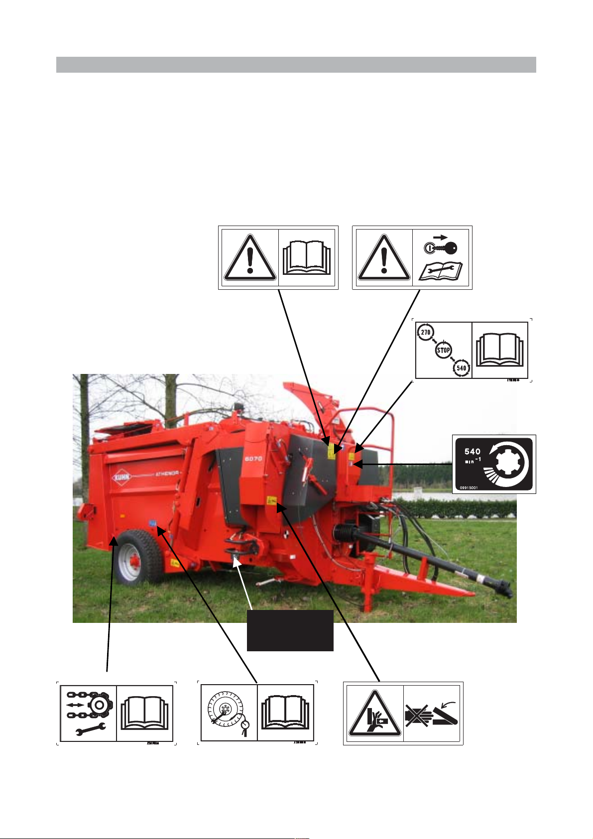
Your machine features a number of adhesive labels as shown below. These labels contribute to your
safety and the safety of others and help to keep the machine running smoothly. Read them and check
their position. Go over the labels and the instructions contained in the user manual with the machine
operator.
Keep the labels clean and legible. Replace them if damaged.
1.2 SAFETY LABELS
Manufacturers
Identification
Plate
12
Page 13
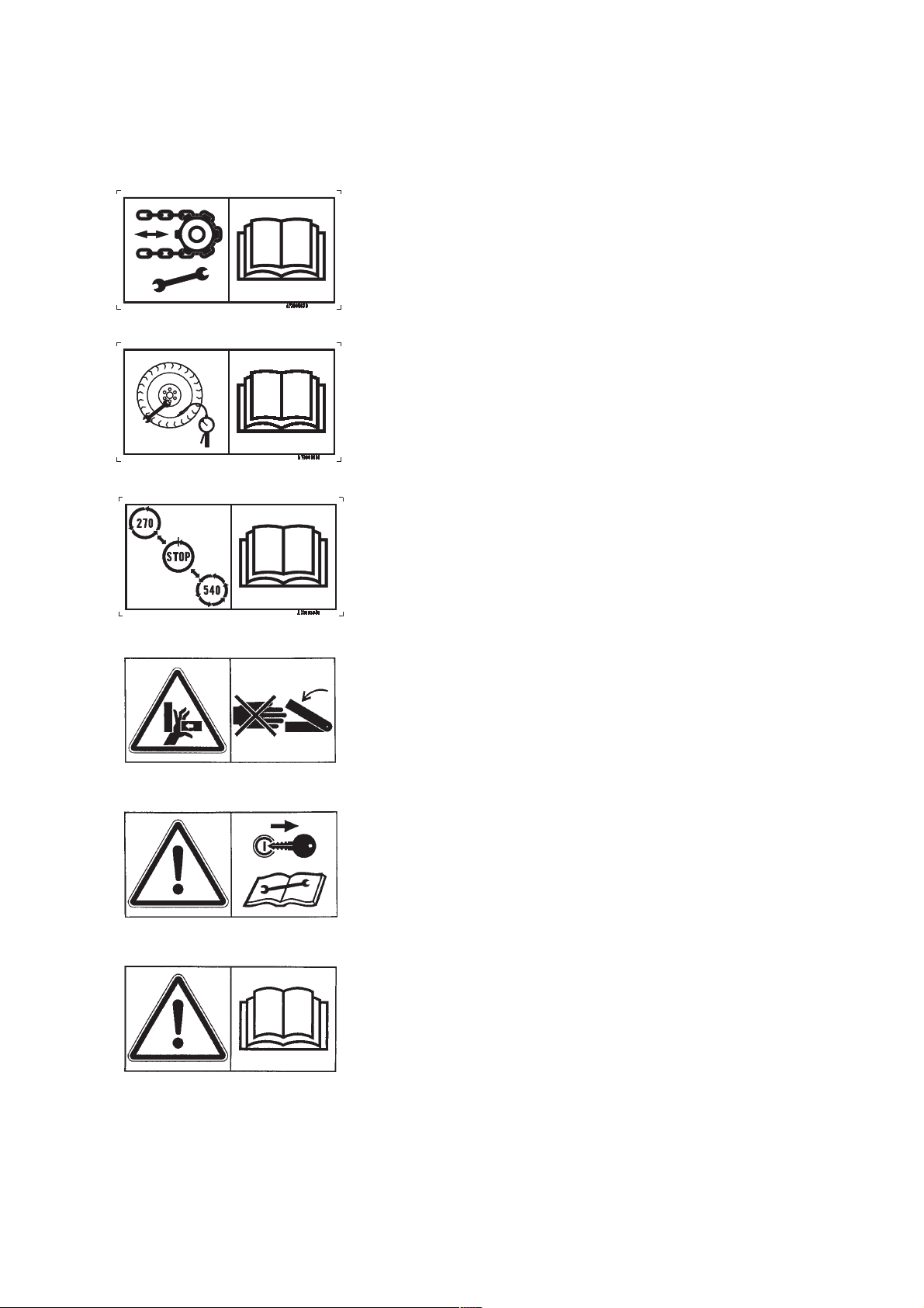
CHECK CHAIN TENSION REGULARLY
CHECK REGULARLY THE TYRES PRESSURE
COMPULSORY.
STOP COMPLETELY TO CHANGE SPEED
ALWAYS KEEP YOUR HAND AWAY FROM THE
CRUSHING AREA UNTIL ALL MOVING PARTS ARE AT
A COMPLETE STANDSTILL
BEFORE CARRYING OUT ANY MAINTENANCE ON
THE MACHINE, SWITCH OFF THE TRACTOR
ENGINE, REMOVE THE KEY FROM THE IGNITION
AND WAIT UNTIL ALL MOVING PARTS HAVE
STOPPED
BEFORE COMMISSIONING THE MACHINE, READ
THE INSTRUCTION MANUAL AND THE RULES OF
SAFETY
13
Page 14
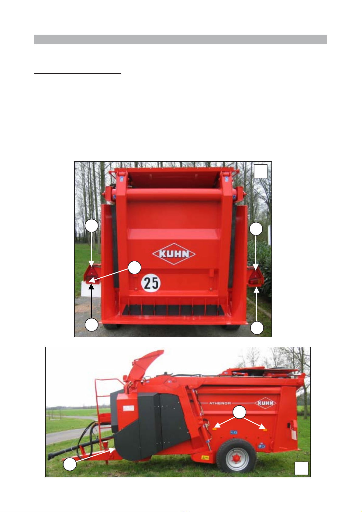
1.3 LIGHTING EQUIPMENT
Altor 6070 - Athenor 6070
Lighting equipment is fitted as standard on the machines in accordance with current legislation.
The equipment includes:
- 2 sets of tail lights comprising a brake light, a side light and a turn-signal indicator (A)
- 2 reflective triangles (B)
- 2 amber reflectors per side (C)
- 2 white reflectors on the front (D)
1
C
A
C
D
B
F
E
2
14
Page 15

NOTES
15
Page 16
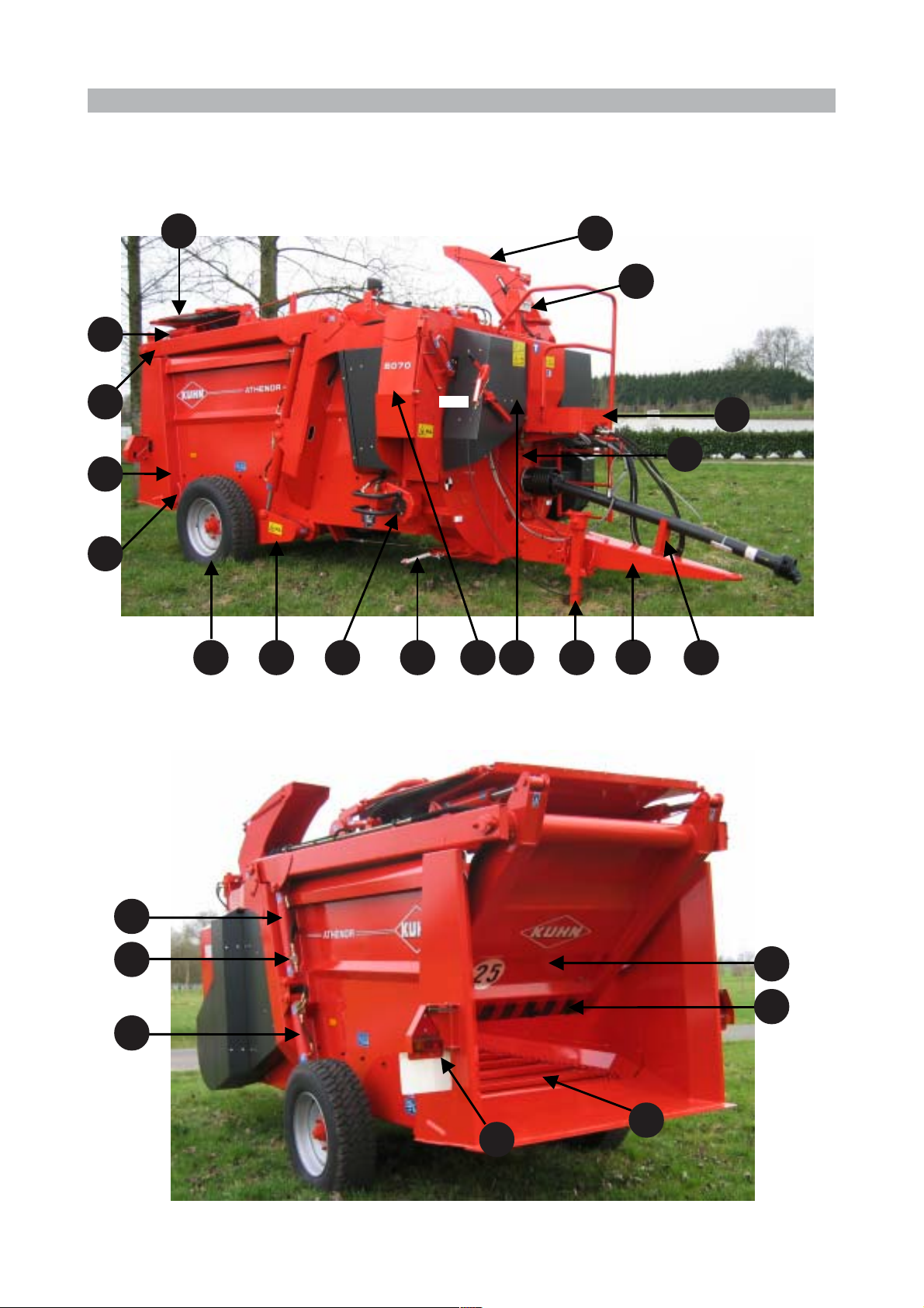
1.4 DESCRIPTION OF THE ALTOR - ATHENOR 6070
14
15
1
25
13
23
12
10
9
16
432
5 8
6
7
17
18
11
24
21
22
20
19
16
Page 17

1 - BODY
2 - WHEEL
3 - AXLE
111
ATHENOR 756011111
4 - PARKING BRAKE
5 - DELIVERY CHUTE
6 - PARKING STAND
7 - TOW BAR
8 - CONTROL UNIT (UNDER THE COVER))
9 - PLATFORM
10 - PLATFORM CONTROLS
11 - ARM RAM SAFETY VALVE
12 - RECYCLING CHUTE on ATHENOR 6070 or
SWIVEL STRAW-BLOWING CHUTE on ALTOR 6070
13 - COVER on ATHENOR 6070
14 - GRAB RAM
1
111
15 - ARM
16 - DRIVE UNIT
17 - DRIVE SHAFT SUPPORT
18 - ARM RAM
19 - TAIL LIGHTS
20 - CONVEYOR
21 - GRAB
22 - GRAB SCRAPER
23 - CONVEYOR REDUCTION GEAR
24 - BODY RAM
25 - EMPTYING FLAP
17
Page 18

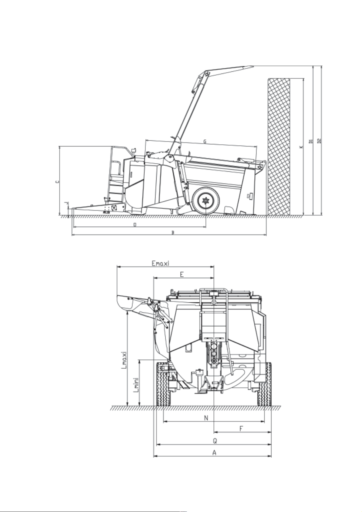
1.5 TECHNICAL SPECIFICATIONS
1.5.1 Altor 6070
Semi-mounted silage loader, straw blower and feeder
,7(0 $/725
Am2.42
Overall width
B
Overall length, m achine on ground
C
Overall height , machine on ground
Max . hei ght requirem ent :
D1* m 4.81
Mac hi ne on ground
D2* m 5.64
Ax l e at m ax. hei ght
E
Offset, chute side (c losed)
E
Offset, chute side (max.)
Fm1.18
Offset, LH side
Gm3.57
Inside body length
Hm1.50
Inside body widt h
I
Inside body height without arm /with arm
Jm0.04
Mini m um hi tch hei ght
K
Max. rec. sila ge l o adi n g he i ght, mac hine on grou nd
Distribut ion height:
L* m 0.73
Min.
Max.
M
Max . recommended s tac k dis charge height
N m 2 062
Track
Om4.25
Wheelbase
Pm2.66
Normal trans port hei ght
Q Wi dth at wheels m 2.36
Unladen weight in work i ng order
Wei ght on axle:
unladen
max.
Wei ght on towing eye:
unladen
max.
Gross weight
Capacity
Working load
Tyres
Tyre pressure
Mini m um tractor power requirement (without haylage)
Mini m um tractor power requirement (with haylage)
Required tractor press ure
Min. tractor output
Max . tractor output
'(),1, 7, 21
m6.25
m2.22
m1.24
2,00
m 1.32 / 1. 52
m4.40
m2.29
m4.40
kg 3 960
kg 3 080
kg 4 800 at 30 k m / h
kg 880
kg 910
kg 5 710
3
m
kg 1 750
285 x 70 R 19.5
bar 6.5
HP (kW) 65 (48)
HP (kW) 80 (59)
bar Min. 170 - Max. 190
l/ m in 30 at required pressure
l/ m in 60 at required pressure
6
* Depending on tractor (take account of lifting height)
Options: - Hydraulic unit - Swivel chute
- Free wheel homokinetic transmission - Minerals hopper
18
Page 19
19
Page 20

1.5.2 Athenor 6070
Semi-mounted silage loader, straw blower, mixer and feeder
,7(0 $7+(125
Am2.42
Overall width
B
Overall length, m achine on ground
C
Overall height , machine on ground
C1 m 2.46
Cover folded
C2 m 2.76
Cover unfolded
Max . hei ght requirem ent :
D1* m 4.81
Mac hi ne on ground
D2* m 5.64
Ax l e at m ax. hei ght
E
Offset, chute side (c losed)
E
Offset, chute side (max.)
Fm1.18
Offset, LH side
Gm3.57
Inside body length
Hm1.50
Inside body widt h
I
Inside body height without arm /with arm
Jm0.04
Mini m um hi tch hei ght
K
Max. rec. sila ge l o adi n g he i ght, mac hine on grou nd
Distribut ion height:
L* m 0.73
Min.
Max.
M
Max . recommended s tac k dis charge height
N m 2 062
Track
Om4.25
Wheelbase
Pm2.93
Normal trans port hei ght
Q Wi dth at wheels m 2.36
Unladen weight in work i ng order
Wei ght on axle:
unladen
max.
Wei ght on towing eye:
unladen
max.
Gross weight
Capacity
Working load
Tyres
Tyre pressure
Mini m um tractor power requirement (without haylage)
Mini m um tractor power requirement (with haylage)
Required tractor press ure
Min. tractor output
Max . tractor output
'(),1, 7, 21
m6.25
m2.46
m1.24
2,00
m 1.32 / 1. 52
m4.40
m2.29
m4.40
kg 4 160
kg 3 250
kg 4 800 at 30 k m / h
kg 900
kg 930
kg 5 740
3
m
kg 1 580
285 x 70 R 19.5
bar 6.5
HP (kW) 75 (55)
HP (kW) 90 (66)
bar Min. 170 - Max. 190
l/ m in 30 at required pressure
l/ m in 60 at required pressure
6
* Depending on tractor (take account of lifting height)
Options: - Hydraulic unit - Free wheel homokinetic transmission
- Programmable weighing system - Weighing system
- Swivel chute
20
Page 21

21
Page 22

1.6 DESCRIPTION OF THE CONTROLS
1.6.1 Electric Controls
For standard machines and machines with a swivel chute
H
A
B
G
C
D
Machine with hopper
E
I
F
A
B
G
D
C
K
J
F
22
Page 23

A- Switching
Controls active and
spotlight on
B- Raising / Lowering the Arm and Body
Raise the arm
Controls in neutral
Controls active
Lower the body
Lower the body
C - Raising / Lowering the Delivery Chute and Opening / Closing the Grab
Open the grab
Raise the body
Raise the chute
Lower the chute
Close the grab
23
Page 24

D - Feed Rotor On / Off
Feed rotor on Feed rotor off
E - Conveyor Forward / Reverse
Indicator lamp
Conveyor in forward
motion
The feed rotor clutch is hydraulically controlled. The lever must therefore
be held for a few moments in the required position until the green LED
lights up. Similarly, the feed rotor is only completely disengaged if the
lever is held in position for a few seconds until the green LED goes
out.
F - Adjusting the Conveyor Speed
Conveyor in reverse
The speed is adjusted by a knob graduated from 0 to
10.
Position 0 corresponds to zero conveyor speed.
Note:The conveyor speed is not exactly proportional to the graduation.
24
Page 25

G - Deflector
Regulator down
(hay and
haylage)
H - Swivel/Recycling Chute Shutter
Regulator up
(recycling, silage
feeding and straw
blowing)
Swivel / Recycling
chute position
Delivery chute
position
Shutter positioning is controlled hydraulically. As this takes a little time,
the lever must be held in the required position for a few seconds.
25
Page 26

1.6.2 Optional Equipment Controls
The controls supplied with a machine equipped with an optional mixing hopper or swivel chute will be
identified as described in the Description of the Controls section. The knobs and levers marked A
and F therefore have identical functions. This part of the manual will therefore focus on the knobs
used to control the mixing hopper or the swivel chute.
1 - Swivel Chute Controls
I - Raising / Lowering the Tip and Swivel Chute Rotation
Raise the tip
Rotate to the
left
2. Mixing Hopper Controls
J - Mixing Auger Rotation
Rotate to the
right
Lower the tip
When the lever is up to the right, just the conveyorfeed rotor assembly runs in the forward direction.
When the lever is down to the right, just the conveyorfeed rotor assembly runs in the reverse direction.
When the lever is down to the left, the conveyor-feed
rotor assembly runs in the reverse direction and the
mixing auger rotates.
When the lever is left of centre, just the mixing auger
rotates.
When the lever is up to the left, the conveyor-feed rotor
assembly runs in the forward direction and the mixing
auger rotates.
26
Page 27

K - Adjusting the Injection Speed
The speed is adjusted by a knob graduated from
0 to 10.
Position 0 corresponds to zero injection screw
speed.
Note: The injection auger output rate is not exactly proportional to the graduation.
Calibration according to product type may prove necessary. Refer to the mixing hopper
instruction manual supplied with the machine.
27
Page 28

1.6.3 Electric Controls from the Platform
A
A - Raising / Lowering the Arm and Body
Raise the arm
Lower the body
B
Raise the body
B - Opening / Closing the Grab
Lower the arm
Open the grab
Close the grab
28
Page 29

1.6.4 Changing the Turbine Speed
The gear control lever is located on the front of the machine.
This lever has three positions (for a PTO speed of 540 rpm):
- 0 loading a machine equipped with a hydraulic unit
- 540 min
- 270 min
-1
straw blowing
-1
feeding
Follow this procedure to change speed:
- Switch off the tractor PTO.
- Set the lever to the required position.
- Restart the PTO gently until the new gear engages automatically.
29
Page 30

2. STARTING UP
The Altor & Athenor 6070 are supplied with a safety system fitted to the delivery chute ram. The
purpose of this system is to lock the chute ram for transport in total safety.
The system consists of a metal bar restricting the two shafts
of the chute ram and clamps which must be removed when
the machine is commissioned.
The bar must be removed before any attempt is made to open the chute.
Removal procedure
- Take the clamps (A) off the bar.
- The bar (B) should come freely away from its seat.
For your safety, never try to pull
the bar by hand.
- Operate the hydraulic control of the delivery chute to close
it fully.
- The bar should now come freely away from its seat.
B
A
30
Page 31

2.1 HITCHING
Note: Before hitching the machine to the tractor, make sure that there is sufficient
ballast on the front axle of the tractor.
Ballast should be added to the special supports according to the tractor
manufacturers instructions. The front axle load must be not be less than 20%
of the unladen tractor weight.
2.1.1 Hitching the Machine for Use on Public Roads
- Using the parking stand, set the towing eye to the
required height.
- Back up the tractor and lift the parking stand once
the machine is hitched.
- Lock the hitch with the special device.
- Couple the hitch safety cable to a fixed point on the
tractor frame with the snap link.
1
2.1.2 Hitching the Machine for Use on the Farm Only
2
- Fit the drawbar (1) onto the lifting arms.
- Lock the drawbar (1) with 10 mm clips (2) (not
supplied).
- Back up the tractor until the towing eye is lined up with the pin hole in the drawbar.
- Insert the pin and fasten it.
- Once the machine is coupled up, stabilise the drawbar laterally with the device provided for this
purpose (bar, chain, chocks, etc.).
2.2 ADJUSTING THE POSITION OF THE CONTROLS
The electric control unit can be mounted in the cab as the user requires. The speed control lever
can be mounted either on the tractor or on the machine.
31
Page 32

2.3 UNIVERSAL DRIVE
- At maximum overlap (with the drive shaft compressed),
there must be a safety gap of B = 20mm to prevent the
tubes striking the jaws.
- At maximum extension, there must be a tube overlap of A
= 330 mm.
- If the above conditions are not met, shorten the tubes and
their guards by the same length.
- Round off and clean the tubes and grease the inside of the
outer tube.
To avoid the risk of a serious accident,
make sure that the universal drive
shaft guards are properly fitted and
prevented from rotating by the special
chains.
On the machine side, fasten the chain
to the ring (1) located on the header
retaining disc on the gearbox.
Replace any worn or damaged guard
immediately.
Fig. 4
Fig. 5
1
On unhitching the machine from the tractor, the drive shaft must always be rested on the support on
the machine tow bar. This support must be folded away when the machine is hitched to the tractor.
2.4 CONNECTIONS
2.4.1 Hydraulic
When using the machine with tractors with an oil flow rate in excess of 60 l/min, a flow dividing system
must be provided to prevent the circuit from overheating.
If your tractor is equipped with a closed-centre hydraulic circuit, make
a return to the filter (except on machines equipped with an optional
hydraulic power unit).
32
Page 33

2.4.2 Machines without an Auxiliary Hydraulic Unit
In order to power the machines independent distributor, the machine can be connected to the tractor
hydraulics in one of three ways:
- Connection to a single-acting distributor and direct return to the tank (strongly recommended).
- Connection to a double-acting distributor. The first port is used to connect the pressure hose and the
second for the return hose. On fitting, make sure that the direction of oil flow is correct.
- Connection to a line from the tractor.
For optimum user-friendliness, it is strongly recommended that the original hydraulic distributor on the
tractor be equipped with a continuous pumping position.
The operating pressure of the hydraulic circuit is 190 bar. The minimum and maximum hydraulic oil
flow for a standard machine is 30 l/min and 60 l/min respectively.
The pressure and return hoses are equipped with a male push-pull coupler (ISO 7241). The pressure
hose is identified by a white arrow on a red background, pointing from the tractor to the
machines hydraulic distributor. The return hose is marked by a white arrow on a blue
background, pointing from the distributor to the tractor. Before connecting, make sure that the
couplers are clean. The plastic caps must be used when the machine is not hitched to the tractor.
Once the various hoses have been connected up, make sure that there is no risk of them catching in
operation.
When the machine is not hitched to the tractor, all
hydraulic hoses must be put back in the special
support.
2.4.3 Machines Equipped with an Optional Hydraulic Unit
With this option fitted, the machine is totally independent of the tractors hydraulic circuit. There is
therefore no hydraulic connections to be made before the machine can be used.
33
Page 34

2.4.4 Electric
The machine is supplied as standard with a separate harness
to be connected by your dealer to the + and - terminals on
your tractor battery (brown wire to + and blue wire to -).
A second power cable can be ordered for another tractor
under reference A7040170.
The electric power cable must be connected directly to the
battery for a constant, even electric power supply to the
machines controls.
Certain tractors are equipped with this type of 3-pole serial plug. To
avoid any malfunctions, the polarity of this plug must be checked.
On mounting the electric power cable, beware of shearing, burning on the exhaust pipe, etc.
Next connect the plug and socket to power the control unit. The electric control unit is fitted with a fuse
(see table) and the tractor-side harness with a 30 A fuse (P/N. A7040926).
&RQWURO XQL W
MACHINE ATO-ty pe fuse 30A fuse
ZLWKRXWVZ L YHOFKXWH
ZLWKVZLYHOFKXWH
ZLWKPL[LQJKRSSHU
15A A 7040915 A7040926 A7040170
20A A 7040932 A7040926 A7040170
15A A 7040915 B0000560 A7040170
7UDFWRUVL GHKDUQHVV
Harness
reference
2.5 PRELIMINARY TECHNICAL CHECKS
This phase is particularly important for your machine to give you full satisfaction. We recommend that
you check all of the following points on delivery.
- Check the wheel bolts and tighten up if necessary to 25 daNm.
- Check the conveyor chain tension and adjust if necessary (refer to the Servicing section).
- Check the tightness of the screws and nuts, particularly those holding tools (knives, conveyor bars,
etc.).
- Check that the safety labels are fitted and legible.
- Lubricate all moving parts (refer to the stickers for the location of the greasing nipples). Use only
manufacturer-recommended grease: refer to the lubricant chart.
- Check the oil level in the gearbox.
- Check the oil level in the conveyor drive unit.
- Check the oil level in the hydraulic unit tank and check the condition of the oil filter (optional).
34
Page 35

2.6 NO-LOAD TESTS
Before using the machine for the first time under a load, it must be
tested to make sure that the tractor-machine combination is in working
order. MAKE SURE THAT THERE ARE NO FOREIGN BODIES OR
ACCESSORIES INSIDE THE MACHINE.
Procedure
- Make sure that you can change PTO speed. If the machine is equipped with a hydraulic unit, check
that the unit can be set to neutral.
As gear shifting is not synchronised, it may be necessary to engage the
tractor PTO quickly and operate the gear control lever at the same time.
-1
- Select a PTO speed (270 or 540 min
- Align the tractor and the machine, then engage the PTO drive and leave the tractor idling.
- Gradually increase the engine speed until the PTO speed reaches 540 min
- Start the feed rotor (check that the LED lights up on the control) then the conveyor (test in both
directions). Now check that the machine is running smoothly and free from vibration. Reduce the
engine speed once again until it is idling.
).
-1
.
If the machine is noisy or vibrating abnormally, stop the PTO immediately and refer to the troubleshooting
section or contact your dealer. When the problem has been solved, start the test procedure again
from the beginning.
- Operate the hydraulically-controlled components and check the operation of the machine.
- Stop the PTO, switch off the control unit and switch off the tractor engine.
Should one of the hydraulic functions fail to work or should it run in the wrong direction, check the hose
connections and start the test procedure again from the beginning.
- Finally check that the lighting and singalling equipment (side lights, brake lights and turn-signal
indicators) are in good working order.
2.7 UNHITCHING
- Before unhitching the machine, bring the grab inside the body and lower the arm completely (ram
rods fully retracted).
- Lay the machine on the ground so that it is stable (adjust the parking stand if necessary).
- Before unhitching the machine, switch off the tractor engine and take the key out of the ignition.
- Uncouple the hydraulic pressure and return hoses and the electrical connections.
- Apply the machines parking brake.
- Remove the hitch safety cable.
- Unhitch.
35
Page 36

3. MACHINE OPERATION
RECOMMENDATIONS FOR USE
Before carrying out any maintenance on the machine, switch off the
tractor engine, take the key out of the ignition, wait until all moving
parts are at a standstill and uncouple the universal drive shaft.
3.1 LOADING SILAGE
If the machine is equipped with a hydraulic unit, the speed control unit
must be set to neutral.
3.1.1 Approaching the Silage
- Set the hydraulic distributor control lever to the continuous
pumping position.
- Raise the arm and grab as far as possible to ensure good
visibility and prevent the silage from collapsing as a result
of a collision.
- Lower the machine as far as possible without the heel plate
scraping the ground then back up to the face of the silage.
- Put the heel plate of the machine on the ground just before
coming into contact with the silage.
Note: In the case of a silage clamp, position the machine slightly aslant in order to load as close as
possible to the wall.
Never attempt to back your way into the silage by force.
3.1.2 Loading the Machine
Always start by cutting the silage
from the top.
- From the tractor cab or the platform, position the grab so
as to cut away a chunk of silage about 40cm thick.
- Move the grab back and forth while slowly lowering the
arm.
- When the claw is down, bring it back inside the body while
raising the arm for optimum loading.
36
Page 37

- Raise the arm with the grab inside the body and
repeat the loading operation until the machine is
completely full.
- When the machine is loaded, bring the grab into the
tailgate position without overpacking the silage
against the feed rotor.
Never overpack the silage
against the feed rotor
3.2 LOADING BALES
If the machine is equipped with a hydraulic unit, the speed control unit
must be set to neutral.
3.2.1 Round Bales (1.35 x ø 1.80)
- Raise the arm and the grab for good visibility.
- Back the machine up to the bale and position
the heel plate as close as possible to the
ground.
- Envelop the bale by fully extending the grab
and bringing down the arm until it comes into
contact with the bale.
- Keeping the arm in contact with the bale,
back up slowly. When the bale starts to enter
the machine body, finish off by combining
grab and arm movements.
- Raise the rear end of the machine to keep the
bale inside.
- Raise the arm slightly to decompress the bale.
- Remove the twine then lower the arm again.
37
Page 38

Note: For easier feeding of hay or haylage or straw blowing with a round bale, we advise you to
make sure that the bale is loaded so that it will unroll naturally. This ensures a better feed
through to the turbine - feed rotor assembly and therefore improves the quality of distribution
or straw blowing.
3.2.2 Cubic Bales (3 x 1.45 x 1.45)
- Raise the arm and the grab for good visibility.
- Back the machine up to the bale and position the heel plate as close as possible to the ground.
- Fully extend the grab and lower the arm until it
comes into contact with the middle of the bale.
- Keeping the arm in contact with the bale, back up
slowly. When the bale starts to enter the machine
body, finish off by combining grab and arm
movements.
- When the bale is loaded into the machine, place
the grab to keep the bale in position, without
overpacking it against the feed rotor.
- Raise the rear end of the machine to keep the
bale inside.
- Raise the arm slightly to decompress the bale
then remove the twine.
Note: It is easier to remove the twine once the bale has been loaded with the twine on the side.
38
Page 39

3.3 REGULATING SYSTEM
The product regulating system, placed above the two feed rotors and at the entry to the turbine, has
two working positions:
- A down position to regulate and chop the product. It is essential
that this position is used for feeding hay and haylage.
- An up position allowing the maximum amount of product to
enter the turbine. This position must be used for recycling,
feeding silage and straw blowing.
Important Note: When recycling long, fibrous products (hay or
haylage) together with silage, it is advisable to
set the regulating system to the down position
at the start of mixing to ensure that the product
is chopped up adequately.
When a round bale core is used for recycling, it must be recycled alone
first of all. The regulators must be kept in the down position.
39
Page 40

3.4 MIXING
- When loading, start with the fibrous products, then
add the minerals and finish with the silage.
Beware: The addition of fibrous products (hay or
straw) increases the volume after recycling.
- Select a turbine speed of 270 min-1.
- Set the regulating system to the up position.
- Put the grab into position with the aid of the index
(1) on the gauge (fig.1).
- Put the shutter and cover into the recycling posi-
tion.
- Hold the control lever for a few seconds until the
operation is completed.
1
1
- Engage the tractor PTO and bring the engine to
its rated speed.
- Engage the feed rotor with the conveyor speed
at 0. Then gradually bring it up to between 3 and
4 (the optimum conveyor speed will depend on
available tractor power and the nature of the
product).
- When mixing is complete, stop the conveyor (set to 0) then the feed rotor, set the shutter and cover
to the feeding position, then disengage the tractor PTO.
2
Recycling chute
Delivery chute
Shutter
40
Page 41

3.5 FEEDING
Select the turbine speed according to the product to be distributed:
-1
- 270 min
- 540 min
Note: We strongly recommend against using the machine with a tractor PTO speed of 540 min-1 in
The chute on the right-hand side of the machine (the delivery chute) can be used for two jobs: straw
blowing and feeding. To achieve top quality work and to put the forage where you want it, the tip of this
chute can be set to one of three positions.
for feeding,
-1
for straw blowing.
economic mode.
Always start the tractor PTO before engaging the feed rotor. Similarly,
the feed rotor must be stopped before switching off the PTO. Failure to
comply with this procedure is very likely to lead to turbine jamming.
- To adjust the position simply by hand, we
recommend opening the chute halfway.
- Take hold of the handle and pull downwards.
- Place the pin in the required notch (the notch
farthest away from the machine body
corresponds to the most inclined tip position).
41
Page 42

Operating tips: To stop feedingmomentarily (posts, obstacles, etc.), simply disengage
the feed rotor (the conveyor stops at the same time).
To avoid the risks of jamming in difficult conditions, watch the engine speed.
Slow down the conveyor, or even reverse the direction of rotation, as soon as
the engine speed drops or the belt begins to slip. In all cases where overloading
occurs, it is important to let the feed rotor empty itself before putting the
conveyor back into forward motion.
NEVER ATTEMPT TO CLEAR PRODUCT AWAY BY HAND OR USING A
TOOL WHEN THE MACHINE IS RUNNING.
When the machine is loaded, we strongly recommend against leaving the
conveyor running in reverse longer than is necessary.
Before starting the feed rotor, make sure that the conveyor speed is set to
position 0 to prevent a load being fed into the turbine.
3.5.1 Feeding
The rate of product output is adjusted by:
- the variation in tractorengine speed: control of the hydraulic oil flow and PTO speed.
- the conveyor speed.
3.5.2 Feeding Silage
- Start up the tractor PTO and bring the engine up to its nominal speed.
- Switch the tractors hydraulic distributor to continuous pumping.
- Set the regulating system to the up position.
- Point the delivery chute downwards such that the machine wheel does not run over the distributed
forage which should be properly channelled towards the ground or into the trough.
- Start up the feed rotor with the clutch (until the indicator lights up).
- To deliver the product, start the conveyor running forwards and adjust
the speed.
- Feed the forage regularly onto the conveyor using the grab.
- When feeding is over, bring the arm and grab right in.
Stop the conveyor and disengage the feed rotor. Close the delivery
chute then disengage the tractor PTO.
Operating tips: The conveyor speed is adjusted by the control unit according to feed speed
and product distribution factors, as well as the type of silage.
42
Page 43

3.5.3 Hay and Haylage
- Start up the tractor PTO and bring the engine up to its nominal
speed.
- Switch the tractors hydraulic distributor to continuous pumping.
- Set the regulating system to the down position.
- Point the delivery chute such that the machine wheel does not run
over the distributed forage which should be properly channelled
towards the ground or into the trough.
- Start up the feed rotor with the clutch (until the indicator lights up).
- To deliver the product, start the conveyor running forwards and adjust
the speed.
- When feeding is over, bring the arm and grab right in.
Stop the conveyor and disengage the feed rotor. Close the delivery
chute then disengage the tractor PTO..
Operating tips: The rotor will feed the turbine more easily if you allow the bale to rotate freely
under the action of the rotor.
It is preferable to reduce the tractor engine speed when feeding is over to limit
projections.
During delivery, it is advisable to raise the rear end of the body to:
- keep round bales up against the feed rotor when the product requires little
power,
- facilitate the rotation of round bales against the feed rotor when the
product is tougher.
The conveyor speed is adjusted by the control unit according to feed speed and
product distribution factors, as well as the type of product.
43
Page 44

3.6 STRAW BLOWING
- Start up the tractor PTO.
- Bring the tractor up to its nominal speed and switch the tractors hydraulic distributor to continuous
pumping.
- Set the regulating system to the up position.
- Point the delivery chute or the optional swivel chute such that the straw is blown where you want it.
- Start up the feed rotor with the clutch (until the indicator lights up if electric controls are fitted).
- To deliver the product, start the conveyor running forwards. The conveyor speed is adjusted by the
control unit according to feed speed and product distribution factors, as well as the type of silage.
- Keep the bale in contact with the feed rotor using the grab.
- When feeding is over, bring the arm and grab right in.
- Stop the conveyor and disengage the feed rotor.
- Put the tractors distributor lever back to neutral, disengage the PTO and switch off the engine.
In certain cases, the first fold on rectangular bales tends to shoot upwards at the start of straw blowing.
Guides bring the product towards the back of the machine. For this reason, it is important not to stop
the conveyor and to let the product drop naturally to the back.
Operating tips: For regular straw blowing, the bale must remain in permanent contact with the feed
rotor without forcing it with the grab.
Raise the rear end of the machine slightly to prevent the core of the bale from being
thrown back by the feed rotor.
In the course of distribution, the machine body height can be adjusted in order to:
- keep round bales up against the feed rotor when the product requires little
power,
- facilitate the rotation of round bales against the feed rotor when the product
is tougher.
We strongly recommend straw blowing after feeding the livestock: this will clean
and dry the machine and eliminate the risk of corrosion by acids.
44
Page 45

Note: Should the turbine or feed rotor become jammed, use the hook mounted inside the housing
on the left-hand side of the machine (see photo below) to pull out the jammed product at the
distribution chute or feed rotor, then use a lever to ensure that the turbine can rotate freely.
45
Page 46

3.7 STORAGE OF CONTROLS
Make sure that the controls are put away after every use to protect them from the weather:
3.7.1 Storage of Electric Controls
Gateless machines:
A hook is provided (A) under the front right-hand
housing
A
Gated machines:
Put the controls away in the protective housing (B)
3.7.2 Storage of Dual Platform Control
To protect the dual control, be sure to close the cover
on the control unit after every use.
B
46
Page 47

4. OPTIONS
The following options are available for the Altor 6070 and the Athenor 6070:
- Hydraulic unit (*)
- Free wheel homokinetic transmission
- Weighing system (*)
- Swivel chute (*)
- Mixing hopper (*)
Note: Options marked (*) are factory-fitted only.
4.1 HYDRAULIC UNIT
The hydraulic unit is designed to provide the hydraulic power required for smooth operation of the
machine.
In particular, it enables tractors with a low hydraulic output to be used while guaranteeing optimum
performance of the functions.
Description: - Auxiliary hydraulic unit
- Driven by tractor PTO
3
- 22 cm
pump - output at a PTO speed of 540 min-1: 60 l/min.
- 60 litre tank with filter and level gauge
- Circuit protected by valve calibrated to 190 bar
- Recommended oil type: ISO VG 46 (HV); e.g. SHELL HYDRAU PW.
A slight gearing noise may be heard at low speeds. We recommend using
the hydraulic unit at a minimum PTO speed of 300 min
-1
.
Operation:
- Before starting up a machine equipped with a hydraulic unit, check the oil level in the tank.
- Connect and lock the transmission to the tractor PTO and to the pump step-up gear drive shaft.
-1
- The machine must be driven at the nominal PTO speed of 540 min
.
Under no circumstances use the tractors 1000 min
-1
PTO.
- Start up the tractor, then gradually engage the PTO to operate the pump.
- Try the various machine controls. Check the pump flanges and the various hydraulic connections
on the unit for leaks.
47
Page 48

- With the aid of the speed control lever, the unit may be used in three ways:
- at neutral, therefore without running the turbine, for all loading operations
- with a turbine speed of 270 min-1 for distribution
-1
- with a turbine speed of 540 min
Maintenance:
- Comply with the safety instructions relating to machine maintenance.
- Periodically check the oil level in the tank. The oil level should not be below the top 1/3 of the gauge.
- Change the hydraulic oil after the first 500 hours of work. We recommend an ISO VG 46 (HV) type
hydraulic oil. For example: SHELL HYDRAU PW.
- Thereafter, refer to the maintenance chart for the frequency of oil changes.
- To change the filter element, unscrew the plug. Take hold of the filter handle and extract the filter +
bowl assembly. To remove the filter, turn 90° anticlockwise and extract it from its cartridge. Clean the
bowl.
- Insert a new filter and lock into position by turning it 90° clockwise.
- Screw in the plug and make sure that the seal is correctly repositioned to prevent leaks.
.
4.2 FREE-WHEEL HOMOKINETIC TRANSMISSION
Transmission assembly providing a greater angle of deflection and free rotation of the turbine.
Before using this equipment, please consult the manual delivered with the transmission.
4.3 WEIGHING SYSTEM
Device used to determine the weight of the ration to be fed to the livestock.
Please read the instructions provided with the weighing system
carefully.
48
Page 49

4.4 SWIVEL CHUTE
Note: The maximum straw blowing distance with the swivel chute is 13 metres.
The swivel chute is an essential item of equipment for farm building with no through access. With its
high angle of rotation, straw can be blown to every position while protecting the driver in the tractor
cab.
Straw blowing device for distribution to the left and
right. The blowing distance is controlled from the
tractor cab thanks to an electrically-powered ram
(see Description of the Controls).
To avoid improper or incorrect use of the chutes (the swivel chute must not be used to distribute
haylage), the machine is equipped with a shutter position indicator.
Shutter set to swivel chute position
49
Shutter set to delivery chute position
Page 50

Using the optional swivel chute
Athenor recycling machines with a swivel chute are fitted with a valve under the machine platform
(Photo 1). This valve is used to open and close the recycling cover. If it is open, the cover and shutter
switch to the recycling position. If it is closed, only the shutter switches to the recycling position.
1
4.5 MIXING HOPPER
Mixing hoppers with a capacity of 575 litres can be used to add minerals and concentrates to the
coarse forage (maize or grass silage, etc.). Blending takes place in the turbine.
Thanks to its low profile and its two side filling ports,
the hopper can easily be loaded without any special
accessories.
For maximum accessibility, it is advisable to lay the
machine on the ground and lower the tractors lifting
mechanism right down when the machine is coupled
to the drawbar.
50
Page 51

5. MAINTENANCE
Before carrying out any maintenance,
servicing or repair work or when
investigating the cause of failure or
malfunction, you must switch off the
engine, lay the machine down, remove
the ignition key and wait for the moving
parts to come to a complete standstill.
1
Before proceeding with any
maintenance work on a machine in the
raised position, prop up the machine
with an appropriate support.
A
(1)
B
Before any maintenance operation
calling for work inside the body, raise
the machines arm and grab and lock
the arm by positioning the lever (A) of
valve (B) perpendicular to the ram
(position 1).
Remember to release the arm at the end of the operation.
When clearing a blockage or replacing a working part, wear protective
gloves and only use appropriate tools.
Beware! Never pass between the feed rotors to access the turbine.
To avoid environmental contamination, it is forbidden to throw away or
dump any type of oil, grease or filter. Hand them over to collection firms.
Before carrying out any operations on the electric circuit, disconnect
the power source (tractor charging circuit or battery).
Any protective devices liable to wear should be checked regularly.
Replace them immediately if they are damaged.
Spare parts must comply with the standards and specifications laid down
by the manufacturer. Only use Kuhn spare parts.
Before carrying out any electric welding work on the tractor or towed
machine, disconnect the cables from the alternator and battery.
Check the tightness of screws and nuts regularly. Tighten up if
necessary.
51
Page 52

5.1 GREASING
The greasing points are identified by a label featuring a white grease pump on a blue background.
Some grease nipples are located under guards or protective caps.
We strongly recommend that you take the time when your machine is delivered to open all of the
guards to identify the various greasing points. Remember that regular greasing will increase the life of
rotating parts considerably.
5.2 CLEANING THE CONVEYOR
For cleanliness, the conveyor is housed in a case. In order to eliminate the build-up of product from
the bottom of the case, it is preferable to open the shutter once a week.
The following procedure should be applied:
- Shift the original tractor distributor lever to the continuous pumping position.
- Switch on the tractor PTO and engage the feed rotor.
- Start the conveyor in forward motion for a few seconds to bring the built-up product to the back of the
conveyor case.
- Stop the conveyor and disengage the feed rotor followed by the tractor PTO.
- Switch off the tractor engine and remove the key from the ignition.
WAIT FOR A FEW MOMENTS UNTIL THE MACHINE IS AT A COMPLETE
STANDSTILL.
- Pull the locking handles (A) located on either side.
- Release the hooks holding the ring (B).
- Fully open the shutter (C).
- Using a brush or similar tool, remove any product
that may be left behind.
- Lift the shutter and insert the two hooks into the
ring. It is important to hook the rings before lifting
the handles.
- Lift the handles to lock the shutter.
A
C
B
52
Page 53

5.3 CHAIN TENSION
The tension of the chains should be checked after every 100
hours of operation.
If the deflection exceeds 150 mm, the chains need to be
tightened up.
Never fully tighten the chains. Always leave a deflection of at least 50
mm (Figure 1).
Procedure:
Open the shutter (C on photo opposite) according to the procedure described for conveyor cleaning.
Figure 1
- Loosen check nut (D).
- Tighten up nut (E).
- Tighten check nut (D).
- Make sure that both sides of the conveyor are
tightened by identical amounts.
- Close the shutter as described in the section
on conveyor cleaning.
E
C
D
Note: When the chain tension adjuster has reached its limit of travel, the left and right-hand chains
can be shortened by two links.
53
Page 54

5.4 ADJUSTING BELT TENSION
In order to guarantee optimum system operation, belt tension needs to be checked and adjusted if
necessary every 100 hours, or more often if difficult products are frequently distributed.
Belt tension is adjusted using the screw rod (A), nut (B) and check nut (C).
In the engaged position, the end of the spring should be level with the indicator (
Left-hand side drive (lower feed rotor)
I
A
C
I).
B
Right-hand side drive (upper feed rotor)
A
C
B
I
54
Page 55

5.5 CHECKING AND ADJUSTING THE SECTIONS
Check the position of the regulating tines in relation to the sections regularly.
- Outer regulating tines (A): these
tines must be centred in relation to
the sections passing on each side.
- Inner regulating tines (B): the
distance d between these tines
and the sections must be less than
10 mm. The non-bevelled side must
be facing the regulating tine to cut
the product correctly.
A A
B
To adjust the position of the regulating
tines in relation to the sections, add or
remove shims (C) (Ref. A5204400).
C
For this separating system to work
efficiently, the sections must be sharp:
grind or replace them if necessary.
You can swap the sections around in
order to use both cutting edges of each
section.
d
55
Page 56

5.6 STORAGE
If the machine is not to be used for a long period, prepare it for storage as follows:
- Clean the body (inside, outside and underside), the arm and the grab. Remove any product build-
up. If necessary, repaint any surface in danger of rusting. Grease the underbody.
- When using a pressure cleaner, pay attention to the sensitive areas (ram joints, electrical
connections, etc.).
- Bring the ram rods right in to protect them from moisture and dust.
- Grease the drive chains.
- Check that the belt is slack.
- Clean all greasing points and joints. Grease.
- Where possible, store your machine in a sheltered area on blocks to protect it from ground damp.
- Check tyre pressure and wheel bolt tightness.
Transmission
Refer to the instructions supplied with the transmission assembly for the frequency of maintenance.
56
Page 57

5.7 OIL CHANGE AND LEVEL CHECKS
5.7.1 Gearbox
The gearbox must always have sufficient oil. Its capacity is 5 litres.
To drain
- Unscrew the fill plug (A).
- Place a container under the drain hole and unscrew the drain
plug (B).
To fill
- Replace the seal if necessary and refit the drain plug.
- Unscrew the level gauge plug (C) and fill the gearbox using a
funnel.
- Stop filling as soon as oil seeps through the level gauge hole.
- Refit the level gauge and fill plugs.
A
C
B
5.7.2 Conveyor Reduction Gear Unit
To drain
- Unscrew the fill plug (A).
- Place a container under the reduction gear
unit and unscrew the drain plug (B).
To fill
- Refit the drain plug.
- Unscrew the level gauge plug (C) and fill
the gear unit with ISO CKC 150 type oil, such
as SHELL OMALA 150.
- Stop filling as soon as oil seeps through the
level gauge hole.
- Refit the plugs (A) and (C).
A
C
B
57
Page 58

5.7.3 Step-Up Gear Unit
(If the optional hydraulic unit is fitted)
To drain
- Unscrew the fill plug (A).
- Place a container under the step-up gear unit and unscrew
the drain plug (B).
To fill
- Refit the drain plug (B).
- Fill the gear unit with ISO CKC 150 type oil, such as SHELL
OMALA 150 (to 1 cm below level).
- Refit the plug (A).
5.8 MAINTENANCE SCHEDULE
A
B
Warning: The schedule indicated below has been calculated for normal conditions of use. If the working
conditions of the machine are more demanding, the intervals should be reduced.
&RPSRQHQW
Gearbox
(capacity 5 litres)
Reduction gear
(capacity 1.5 litres)
Step-up gear
(for the optional hydraulic unit)
(capacity 0.5 litre)
Greasing
Hydraulic unit oil tank
(capacity 60 litres)
5H FRPPH Q G H G
OXEULFDQW
SHELL
OMALA 150
SHELL
OMALA 150
SHELL
OMALA 150
SHELL
RETINAX EP 2
SHELL
HYDRAU PW
,62VWDQGDUG 6$(VWDQGDUG
CKC 150 SAE 80 W 90
CKC 150 SAE 80 W 90
CKC 150 SAE 80 W 90
VG 46
(HV)
SAE 15 W
58
Page 59

5.9 SUMMARY MAINTENANCE SCHEDULE
Check wh eel bolt t ight ness (25 daNm) and
tyre pressure (5.5 bar)
Check nut s and screws, partic ularly the
ones fastening the tools (sections)
Tight en draw bar eyebolts
$IWHU
$IWHU
KRXUV
2QHYHU\XVH
;;
;; ;
(YHU\
KRXUV
KRXUV
;;
$IWHU
(YHU\
KRXUV
(YHU\
KRXUV
KRXUV
(YHU\
(YHU\
KRXUV
KRXUVRU
HYHU\\HDU
Check t he belt tension
G rease and check t ension of upper f eed
rotor driv e chain
G rease arm, grab, axle and regulating
syst em jo i n ts
G rease grab, axle and arm rams
G rease the chu t e ram
G rease the f eed r ot or bearings
G rease the swiv el chut e bear ing (if f it t ed)
G rease the con vey or
G rease the park ing stand
G rease the con vey or rot ation indicat or
Change the gear box oil
Change the oil in th e conveyor reduct ion
gear unit
Change the oil in th e step-up gear unit on
the hydraulic unit (if f it t ed)
;;
;;
;;
;;
;;
;;
;;
;;
;;
;;
;;
;;
;;
Change the oil in th e hydraulic unit (if f it t ed)
Change the f ilt er c art r idge on t he hydraulic
unit (if fitted)
Check t he conveyor chain tension
Check t he gearbox level
Check t he conveyor reduct ion gear unit
level
Check t hat the safety guards are fitted and
in good condition. Replace if nec essary.
Check t hat the safety labels are fitted and
legible
Check moving parts for wear. R eplace if
necessary using original KUHN par t s.
Clean the machine (body, ar m and grab).
Av oid splashing electrical c omponents, t he
belt, et c .
;;
;;
;;
;
;
;
;;
;;
;
59
Page 60

6. TROUBLESHOOTING
Problem What to do
l Insufficient grab power - Check that the hydraulic connections between the
tractor and the machine are correct (pressure and
return).
- Check the hydraulic pressure (190 bar) and the pump
output (35 l/min). The return pressure must be 8 bar
maximum at the nominal tractor speed.
l Hydraulic functions fail - Check that the hoses are correctly connected to the
to operate tractor distributor (make sure that the valves are opening
as dirt can hinder correct operation).
- Make sure that the voltage provided by the battery is over
11 V.
- Check that the original tractor distributor is set to the
continuous pumping position (except with auxiliary
hydraulic unit).
- Check that the control unit is switched to 1 or 2.
- Check that the control unit power cable is plugged in.
- Check that the battery power is reaching the socket.
- Check the polarity of the socket.
l The conveyor fails to run - Check that the feed rotor is engaged and the indicator is
lit (see section 1.6 Description of the Controls).
- Open the left-hand side hood and check that the belt
tension roller ram rod is fully retracted.
- Check that the circuit breaker sensor on the feed rotor
clutch is activated.
The sensor mounted on the feed rotor clutch ram prevents
conveyor operation if the feed rotor is not engaged.
The photograph opposite shows the position of the clutch
ram when the feed rotor is rotating.
It is essential that the clutch ram rod is fully retracted for
the circuit breaker sensor to be activated.
60
Page 61

l The conveyor stops rotating in
the course of work
- Check the hydraulic connections for leaks.
- Check that the feed rotor is engaged and the indicator is lit
(see section 1.6 Description of the Controls).
l The feed rotor and the conveyor
stop rotating in the course of
distribution
l Turbine fails to rotate and - Check that there is no product build-up in the turbine.
overload clutch slipping If this is the case, use the hook mounted on the left-hand side
- Check the hydraulic connections for leaks.
- Check that the indicator is lit (see section 1.6 Description of
the Controls).
- Check that the clutch is fully engaged (ram rod fully retracted,
see photo above). If not, make sure that the clutch ram does
not have an internal leak.
of the machine to pull out the jammed product at the delivery
chute or feed rotor, then use a lever to ensure that the turbine
can rotate freely. Once released, run the turbine empty for a
few seconds until it reaches its normal working speed.
You can also gain access to the turbine interior via the
flap (A) on the front of the machine.
A
Should the turbine become jammed, a special hook must be used to
unblock it (see page 44). In view of the high inertia of this system, forcing
the turbine disc to move manually can lead to serious risks of having a
finger severed by a blade.
61
Page 62

l Turbine rotating, feed rotor engaged - Check the conveyor speed setting. Position the
but no product appears. setting knob at the required graduation mark.
- Make sure that the product to be distributed is not
packed against the feed rotor. Release the pressure
on the product inside the machine body by opening
the grab slightly. It is also possible to switch the
conveyor briefly to reverse and then back to forward
motion.
l Turbine rattling when PTO engaged - Engage the PTO gradually at the recommended
speed. If the tractor is equipped with a hydraulic PTO
clutch, contact the dealer to solve the problem with
the progressive clutch rate irrespective of tractor
engine speed.
l Arm lowered too slowly or too - The arm lowering speed can be adjusted by the flow
quickly or grab fails to move when rate limiter (A) under the left-hand hood of the
arm is lowered. machine.
Note: The arm raising/lowering speed is adjusted at
the factory to achieve two identical speeds.
A
- Unscrew the check screw.
- Turn the wheel to the right to reduce the flow and, in
turn, the lowering speed.
- Turn the wheel to the left to increase the flow and, in
turn, the lowering speed.
- Tighten the check screw.
An excessive arm lowering speed
can damage the arm and the rubber
stops on the machine body, or even
the body itself.
l Belt driving the beater bar slipping
for no apparent reason.
- Check the belt tension (see section 5 Maintenance).
62
Page 63

7. GENERAL CONDITIONS OF WARRANTY
KUHN-AUDUREAU S.A., B.P. 19, 85260 LA COPECHAGNIERE, FRANCE (hereinafter referred to as the Company) hereby
certifies in accordance with the provisions stated below to each original purchaser of new equipment manufactured by
KUHN from an approved KUHN dealer that said equipment is, at the time of delivery to the user, guaranteed against all
construction faults and manufacturing defects, provided that the equipment in question is used and maintained in
accordance with the instructions contained in the accompanying manual.
This warranty covers our equipment for a period of one year from the date of delivery or for 500 hours of operation,
whichever is the shorter.
The date of the invoice to the final purchaser and the return of the warranty card by the dealer to the Company, with the
signature of the dealer and the purchaser, will indicate delivery of the equipment.
The warranty is limited to a money-back guarantee or to the repair at our factory and by our Engineering Departments of
parts which are recognised to be faulty in terms of material or craftsmanship.
The following exceptions shall apply however:
F
- Parts included in the composition of machines but which are not manufactured by KUHN, such as tyres, transmission
assemblies, overload clutches, hydraulic rams, hydraulic distributors, etc., are not covered by the KUHN warranty but by
the respective manufacturers warranty.
- Claims relating to such parts will be handled in the same way as if they were KUHN parts. However compensation will
depend on the warranty agreement of the manufacturer concerned, insofar as the latter acknowledges the validity of the
claim. Obviously the warranty does not apply if the faults are due to normal wear and tear, deterioration or accidents
resulting from negligence or inadequate supervision, misuse, lack of maintenance and/or if the machine has been
damaged in an accident, lent or used for a purpose other than the one intended by the Company.
- Obviously the warranty does not apply if the faults are due to normal wear and tear, deterioration resulting from
negligence or inadequate supervision, misuse, lack of maintenance and/or if repairs have not been carried out by an
approved dealer.
- The warranty is void if alterations have been made to the machine without the express agreement of the Company or if
anything other than OEM parts have been fitted to machine sold by the Company and/or if repairs have not been carried
out by an approved dealer or distributor.
- The Company cannot be held responsible for damage suffered by the machine or its accessories during transport and
handling by any carrier, even outside the legal warranty period. Machines, machine parts or accessories are carried at
the risk of the addressee.
- The Company will not be responsible in the case of a claim or injury involving the owner or a third party, or for the
resulting liability.
- Similarly, the Company cannot be held to pay any compensation whatsoever for the loss of a harvest or any damages
whatsoever due to a flaw, latent defect or breakdown of the machine.
The User is responsible for and shall bear all costs relating to:
F
- routine servicing of the equipment, including lubrication, supervision and maintenance of oil levels, minor adjustments,
etc.;
- the labour required to remove and replace a faulty part or parts and, if necessary, adjustments of the corresponding new
part or parts;
- the dealers call-out charge;
- the transport of machines, machine parts or accessories to the place of repair and the return of the elements in
question to the place of use;
- wear parts, such as belts, tyres, bed chains, knives, teeth, overload clutches, etc., which are not covered by the warranty.
63
Page 64

The warranty is subject to strict compliance with the following provisions:
F
- Commissioning of the equipment by the dealer in accordance with our instructions.
- Return of the warranty certificate duly signed by the dealer and user on commissioning.
- Claims shall only be made on a KUHN claim form and sent by the dealer to the Company within a period of one month
of the date of the incident.
- The claim form shall be completed in a legible manner by the dealer and must include the following information:
. the dealers name, address and customer code
. the purchasers name and address
. exact type of machine
. serial number of the machine
. date of delivery to the purchaser
. date of incident
. number of hours of use
. power of tractor used
. detailed description and presumed cause of the incident
. quantities, references and names of the damaged parts
. date and number of the invoice for replacement parts.
- Damaged parts are to be returned by the dealer to the Company for examination together with the duplicate of the claim
form. Transport costs relating to the return of said parts are to be met by the sender.
- The machine must be serviced and used in accordance with the instruction manual. Only the quantity and grade of
lubricants recommended by the Company must be used.
- The safety measures mentioned in the instruction manual and on the machine itself must be observed and all protective
elements and guards, of any nature whatsoever, must be inspected regularly and kept in perfect condition.
- The Companys decision, irrespective of the subject of the warranty claim, is final and the purchaser agrees to accept
it.
- If the warranty claim is rejected, the dealer has two weeks from the date of receipt of our letter of notification in which to
request the return of the damaged parts. Once this period has elapsed, they will automatically be destroyed.
Further conditions: limits of application and responsibility
F
- The warranty cannot be assigned or transferred to any person without the Companys prior written consent.
- Our approved dealers have neither the right nor the power under any circumstances to make any decision, either
expressly or tacitly, on behalf of the Company.
- The technical assistance provided by the Company or its agents with regard to the repair or operation of equipment
does not involve the Companys responsibility in any way and shall not under any circumstances introduce a novation
or waiver to the conditions of this warranty.
- The Company reserves the right to modify its machines without notice. It will not however be responsible for applying
such changes to machines already sold or in service.
- Furthermore, due to the constant evolution of technology, no guarantee can be given with regard to the description of
equipment provided in any literature issued by the Company.
- This warranty is exclusive of any other express or implicit responsibility of the Company, either legal or by agreement.
The responsibilities of the Company may not under any circumstances exceed those defined hereinbefore.
64
Page 65

CE THIS EQUIPMENT COMPLIES WITH THE LABOUR CODE
. The manufacturer declines all responsibility should use of the equipment not comply with the
recommendations contained in this manual.
. The user shall observe health and safety rules and
Agricultural Insurance Fund recommendations.
. Our safety rules and advice are not restrictive.
65
Page 66

KUHN SA
BP 19 F - 85260 LA COPECHAGNIERE
TEL. +33 (0)2 51 41 47 00 FAX: +33 (0)2 51 41 41 03
www.kuhnsa.com - E-mail: info@kuhnsa.com
Société Anonyme au Capital de 2 530 000 Euros
As it is our policy to make constant improvements to our products,
the characteristics contained in this manual, which are correct on the date
of publication, may be changed at any time without notice
or contestation.
All apparatus in the KUHN range comply with the standards of
the French Ministry of Labour laid down in decree n° 86594 of 14 March 1986
and the departmental order of 14 March 1986.
66
 Loading...