

Page 1

OPERATOR'S MANUAL
AN055AGB C
Silo unloader - Straw
Spreader
ALTOR 6070
AN055AGB C
- English - 02-2010
Page 2

Page 3

Silo unloader - Straw Spreader
ALTOR 6070
$Dear Owner
In buying a Kuhn machine you have chosen wisely. Into it have gone years of thought, research and
improvement. You will find, as have thousands of owners all over the world, that you have the best that
engineering skill and actual field testing can produce. You have purchased a dependable machine, but only
through proper care and operation can you expect to receive the performance and long service built into it.
This manual contains all the necessary information for you to receive full efficiency from your machine. The
performance you get from this machine is largely dependent on how well you read and understand th is manual
and apply this knowledge. Please DO NOT ASSUME YOU KNOW HOW TO OPERATE AND MAINTAIN YOUR
MACHINE before reading this manual carefully. KEEP THIS MANUAL AVAILABLE FOR REFERENCE. Pass
it on to the next owner if you re-sell the machine.
Your KUHN dealer can offer a complete line of genuine KUHN service parts. These parts ar e manufactured and
carefully inspected in the same factory that builds the machine to assure high quality and accurate fitting of any
necessary replacements.
About improvements
We are continually striving to improve our products. It therefore reserves the right to make improvements or
changes when it becomes practical to do so, without incurring any obligations to make changes or additions to
the equipment sold previously.
Designated use of the machine
The silo unloader-straw spreader ALTOR 6070 must only be used for the purpose for which it is designed:
unloading silage from the silo, loading round or rectangular bales, transport, distribution in feeding areas and
spreading straw in animal bedding areas.
Dear Owner
1
Page 4

Silo unloader - Straw Spreader
ALTOR 6070
$Contents
Dear Owner.....................................................................................................................1
Contents..........................................................................................................................2
Identification of the machine.........................................................................................5
Front view..........................................................................................................................................5
Rear view.. .......................................... ... .... ... ... .......................................... ... ... .... ... ... ........................5
Model identification plate ................................................................................................................6
Optional equipment..........................................................................................................................6
Safety...............................................................................................................................7
Description of symbols used in this document.............................................................................7
Safety instructions...........................................................................................................................8
Location and description of safety decals on the machine .......................................................18
Road safety equipment and recommendations...........................................................................21
Machine specifications................................................................................................22
Description and glossary...............................................................................................................22
Technical specifications................................................................................................................24
Sound levels ......... ... ... .... ... ... ... .... ............................................. ......................................................27
Putting into service......................................................................................................28
Description of control elements....................................................................................................28
Coupling and uncoupling..............................................................................................................37
Walkway with dual control.............................................................................................................41
2
Swivel chute....................................................................................................................................42
Mixing hopper.................................................................................................................................43
Contents
Page 5

Silo unloader - Straw Spreader
ALTOR 6070
Instructions for transport............................................................................................ 49
Conformity with the road regulations ... ... .... ... .............................................................................49
Instructions for work...................................................................................................50
Preliminary checks.........................................................................................................................50
Functional check, no load.............................................................................................................51
Silage unloading.............................................................................................................................53
Loading bales.......................................... ............................................. ..........................................55
Adjustment setting.........................................................................................................................57
Distribution.....................................................................................................................................58
Straw blowing.................................................................................................................................63
Optional equipment.....................................................................................................65
Hydraulic unit .................................................................................................................................65
Leg with holes ................................................................................................................................67
Homokinetic transmission with free wheel and friction limiter .................................................68
Weighing unit..................................................................................................................................68
Maintenance and storage............................................................................................ 69
Greasing and oil change................................................................................................................69
Control storage...............................................................................................................................75
Cleaning the conveyor...................................................................................................................77
Conveyor chain tension.................................................................................................................78
Checking and adjusting the sections. ... ... .... ... ... ... ................................................. ... ... ................79
Contents
3
Page 6

Silo unloader - Straw Spreader
ALTOR 6070
Belt tension.....................................................................................................................................80
Changing oil and checking levels.................................................................................................82
Tyres................................................................................................................................................83
Storage............................................................................................................................................84
Maintenance....................................................................................................................................85
Trouble shooting guide................................................................................................86
Limited warranty...........................................................................................................91
4
Contents
Page 7
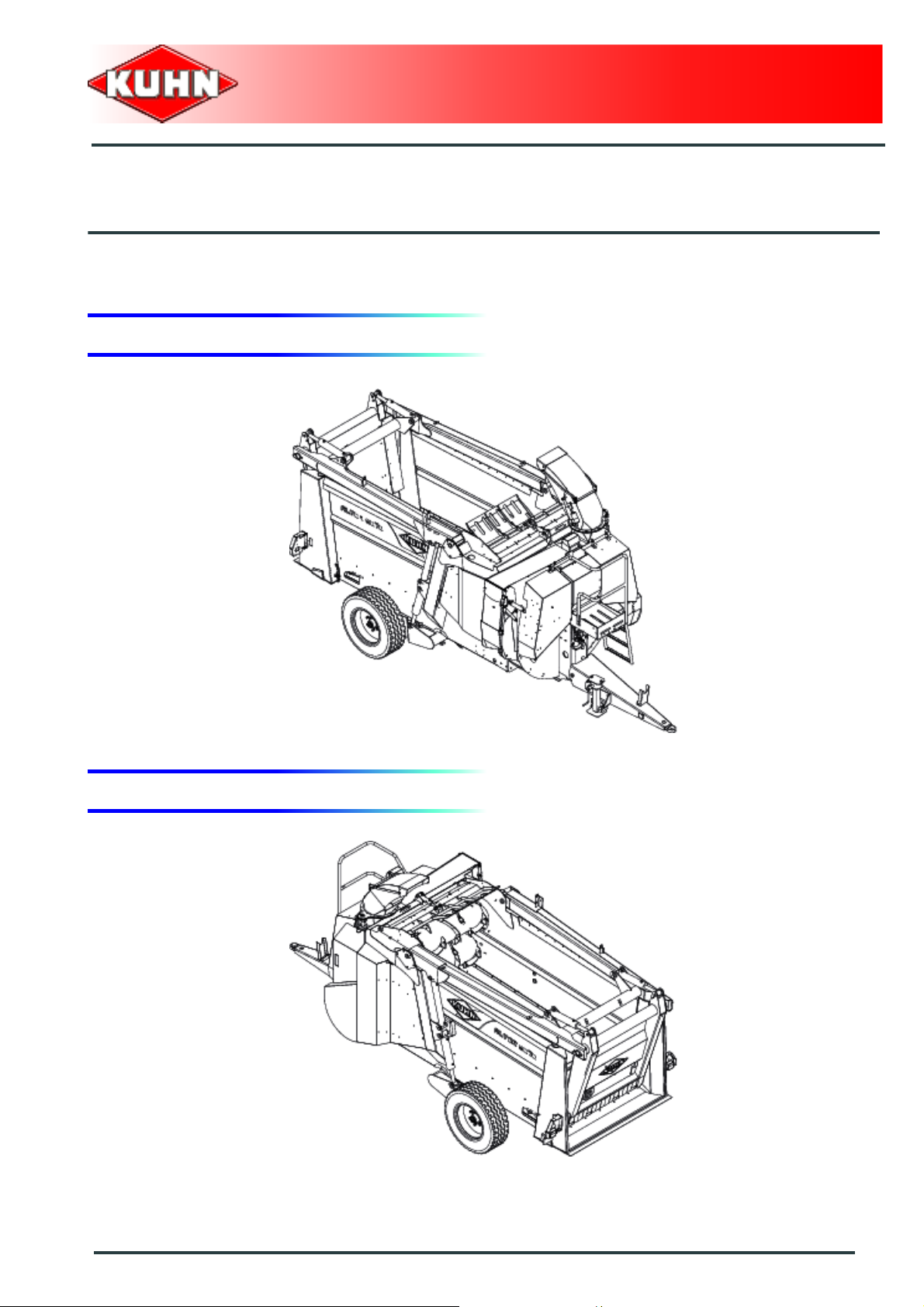
1. Front view
Silo unloader - Straw Spreader
ALTOR 6070
$Identification of the machine
2. Rear view
Identification of the machine
5
Page 8
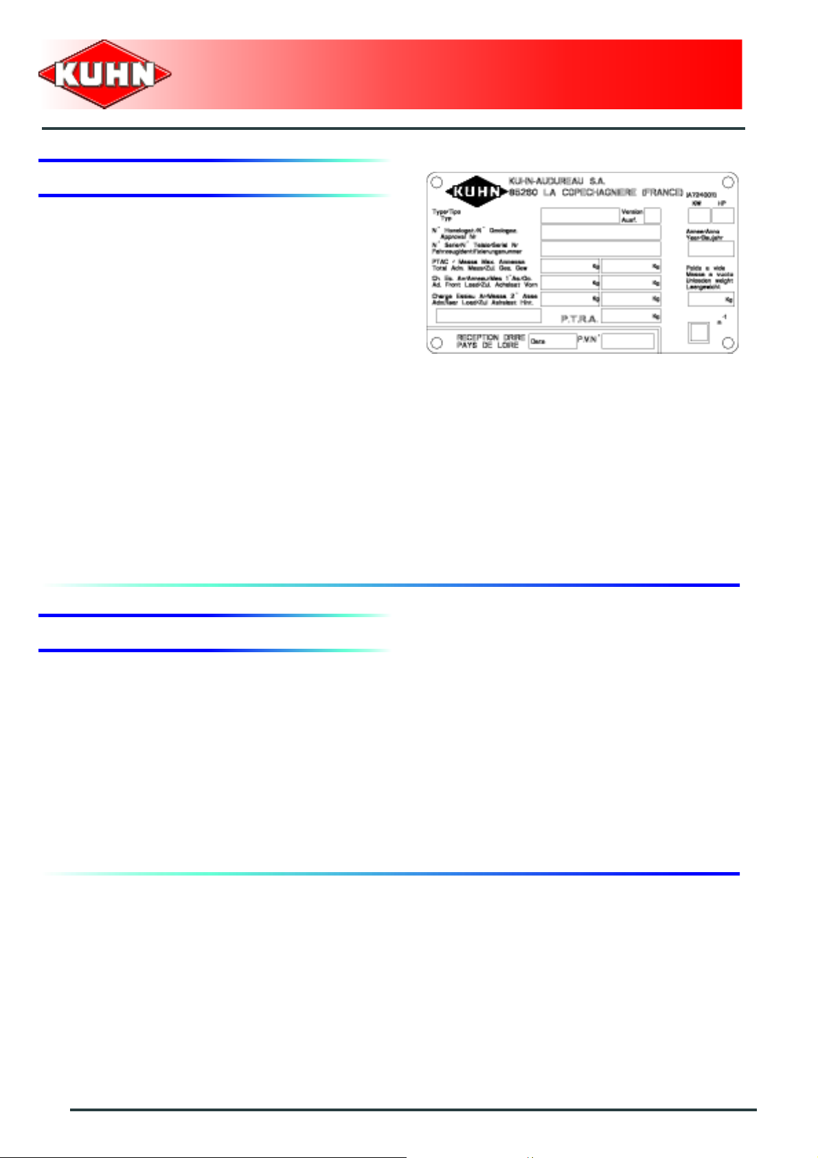
3. Model identification plate
Please write below the type and serial number of the
machine. This information is to be indicated to the dealer
for all spare parts orders.
Type:
Serial no.:
Silo unloader - Straw Spreader
ALTOR 6070
4. Optional equipment
Tick box corresponding to the equipment fitted on your
machine:
Kit no. 1926193: Hydraulic unit
Kit no. 1926207: Weighing unit
Kit no. 1936023: Programmable weighing unit
Kit no. 1926178: Homokinetic transmission with free wheel and friction limiter
Kit no. 1926174: Leg with holes
6
Identification of the machine
Page 9

$Safety
1. Description of symbols used in this document
This symbol indicates a potentially hazardous situation
that if not avoided, could result in serious bodily injury.
Silo unloader - Straw Spreader
ALTOR 6070
This symbol is used to identify special instructions or
procedures which, if not followed strictly, could result in
machinery damage.
This symbol is used to communicate technical
information of particular interest.
Safety
7
Page 10
Silo unloader - Straw Spreader
ALTOR 6070
2. Safety instructions
Introduction
The machine must only be operated, maintained and repaired by competent persons who are familiar with
machines' specifications and operation and aware of safety regulations for preventing accidents.
The operator must imperatively respect safety instructions in this manual and in the warnings posted on the
machine. The operator is also obliged to respect curren t legislation concerning accident prevention, wor k safety
and public traffic circulation.
Designated use of the machine also means following operation, maintenance and repair recommendations
given by the manufacturer, and using o nly ge nuine spa re parts, e qu ipme nt an d accessori es, as reco mme nde d
by the manufacturer.
The manufacturer is not held liable for any damage resulting from machine applications other than those
specified by the manufacturer. Any use other than the designated operation is at the risk and responsibility of
the operator.
The manufacturer is not held liable for any damage or accident resulting from ma chine modifications carried out
by the operator himself or by a third party without previous written agreement from the manufacturer.
Read and follow the safety instructions
Before using the machine, carefully read all the safety
instructions in this manual and the warnings placed on
the machine.
Before starting work, the operator must be familiar with
all machine controls, handling devices and their
functions. It is too late to learn once work has been
started!
Never let anyone operate the machine who is not trained
to do so.
Should you have any difficulties in understanding certain
parts in this manual, please contact your KUHN dealer.
Precautions to be taken before carrying out
any operations on the machine
Before leaving the tractor or before adjusting,
maintaining or repairing the machine, disengage the
PTO drive, turn off the engine, remove ignition key and
wait until all moving parts have come to a complete stop
and apply park brake.
8
Safety
Page 11
Precautions to take before using the machine
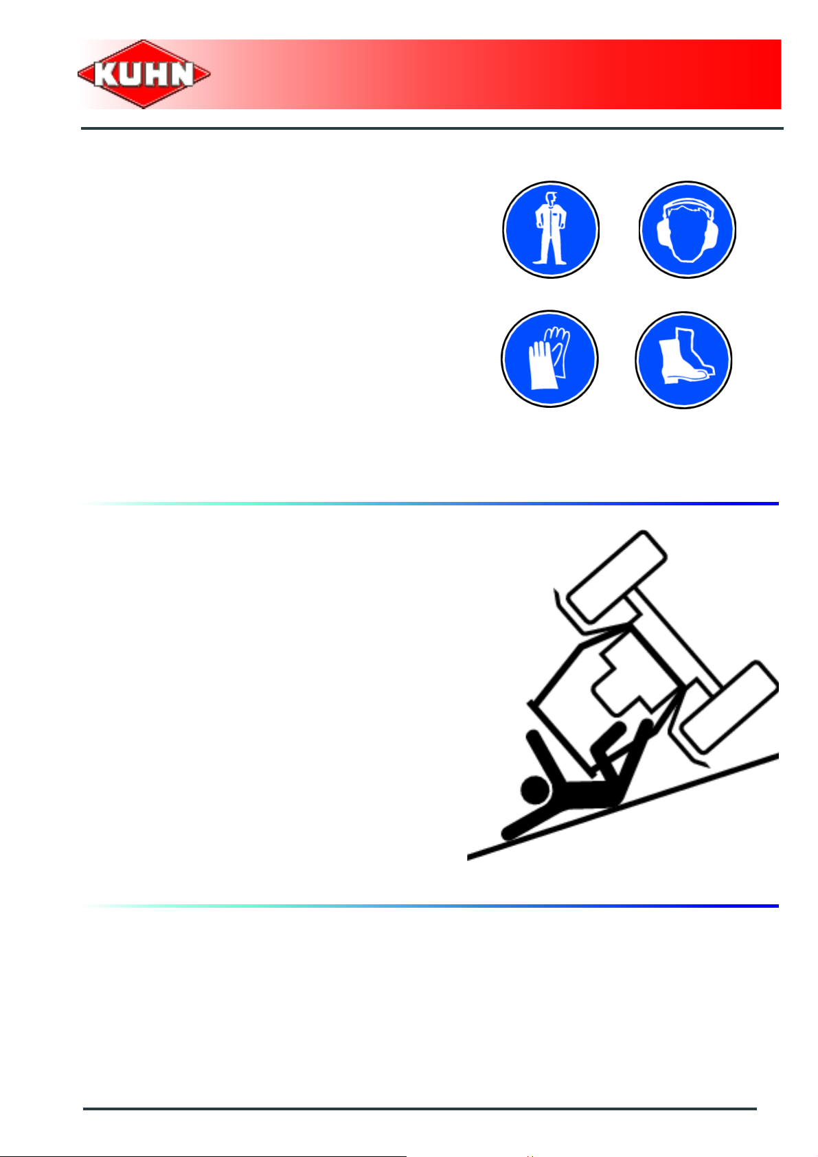
Do not wear loose clothing which could become caught
up in moving parts.
Wear the appropriate protective clothing for the work in
hand (gloves, shoes, goggles, helmet, ear defenders,
etc.).
Ensure that all operating controls (ropes, cables, rods,
etc) are placed so as they cannot be operated
unintentionally and cause damage or injury.
Before operating the machine, check tightness of nuts
and bolts, particularly on fixing elements (tines, forks,
blades, knives, etc). Retighten if necessary.
Before operating the machine, ensure that all the safety
guards are firmly in place and in good condition.
Immediately replace any worn or damaged guard.
Silo unloader - Straw Spreader
ALTOR 6070
Precautions when driving
Tractor handling, stability, performance and braking
efficiency are all affected by weight distribution, trailed or
mounted implements, additional ballast and driving
conditions. It is therefore of great importance that the
operator exercises caution in every given situation.
Groundspeed must be adapted to ground conditions as
well as to roads and paths. Always avoid abrupt changes
of direction.
Be particularly cautious when turning corners, paying
attention to machine overhang, length, height and
weight.
Never use a narrow track tractor on very uneven or
steeply sloping ground.
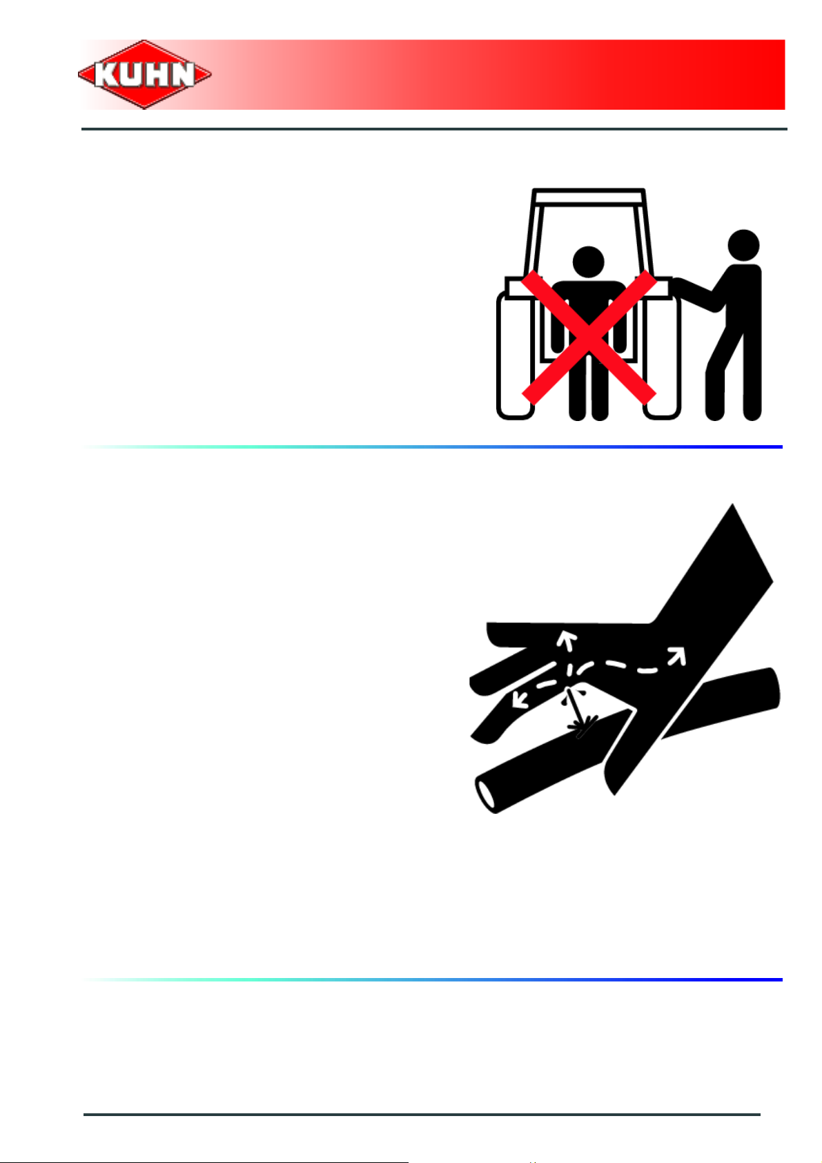
Never leave the tractor seat while the machine is
operating.
Carrying people or animals on the machine when
working or in transport is strictly forbidden.
Safety
9
Page 12
Precautions when driving on public roads
Dimensions
Depending on the dimensions of the machine, contact
the relevant authorities to ensure that it can be legally
transported on public roads.
If the machine is over the maximum legal size, follow the
local regulations for special transportation of oversize
equipment.
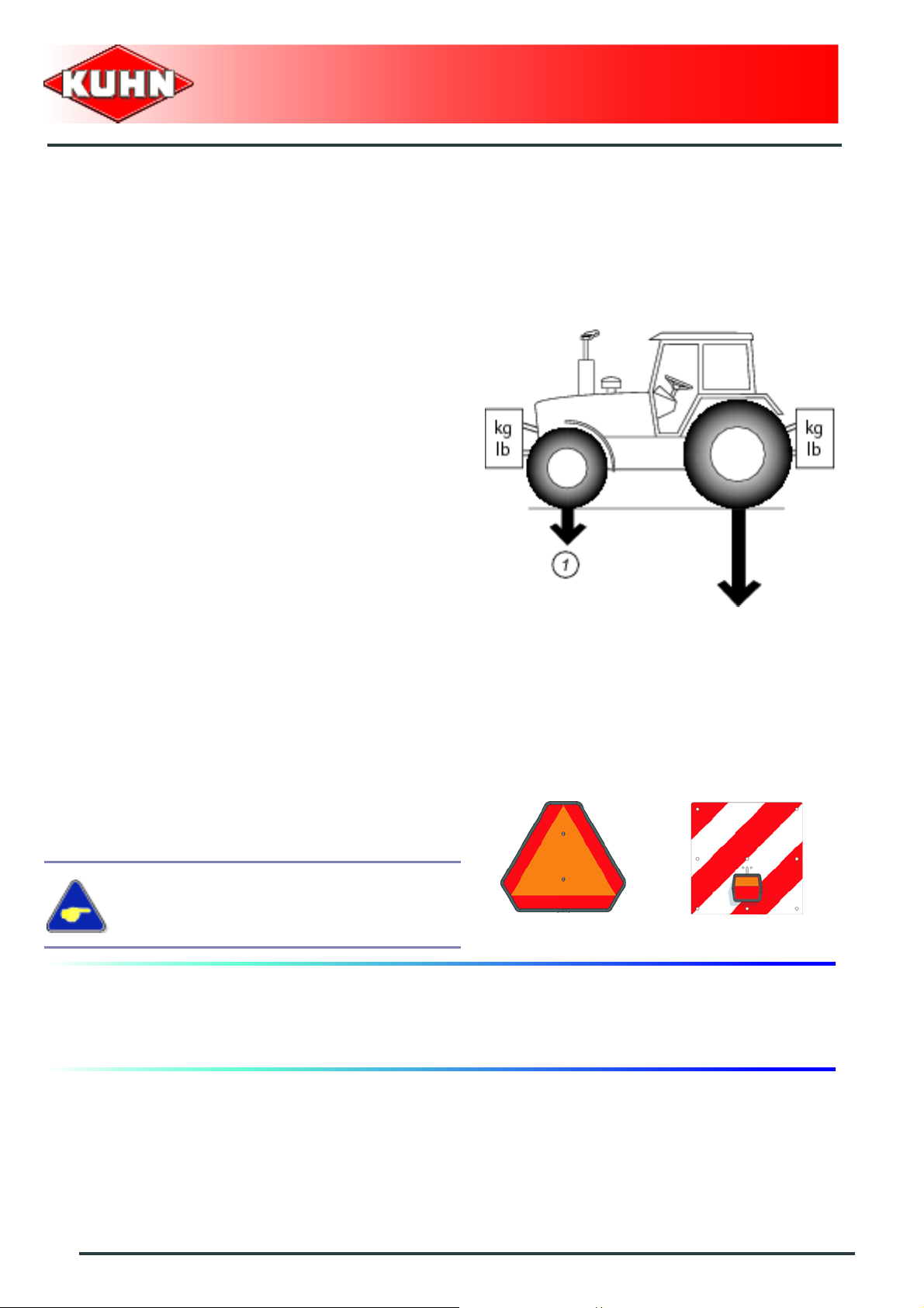
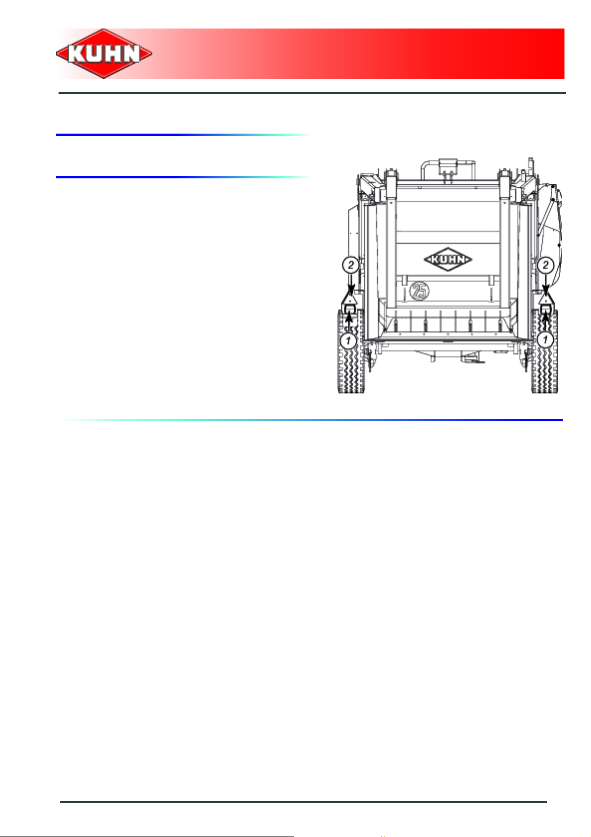
Gross weight and weight per axle
Check that the tractor's authorized gross weight as well
as its lift capacity and maximum weight per axle are not
exceeded.
The front axle load (1) must never, under any
circumstances, be less than 20% of the tractor's unladen
weight. If necessary, add ballast weights to the front or
to the rear to preserve the steering and braking
efficiency.
Silo unloader - Straw Spreader
ALTOR 6070
Transport position
Before transporting the machine on public roads, place
the machine into its transport position, according to the
instructions in this manual.
Lights and indicators.
Before transporting the machine on public roads, ensure
that all legally required lightings and signallings are in
place.
Ensure that lightings and signallings are clean and in
good working order. Replace any missing or broken
equipment.
Always obey current regulations for driving
on roads
Maximum speed
Always keep to the legal speed limit for driving a tractormachine assembly on public roads.
10
Safety
Page 13
Precautions when coupling
Before attaching the machine, make sure that it cannot
accidentally start moving (chock the wheels) and that the
parking stand is in the right position.
The machine must only be attached to the hitch points
provided for this purpose.
Never stand between the tractor and the machine when
operating the three point linkage.
Do not stand between the tractor and the machine
without ensuring that the parking brake is applied.
Hydraulic circuit
Silo unloader - Straw Spreader
ALTOR 6070
Caution! The hydraulic circuit is under high pressure.
Maximum pressure at work: 215 bar.
Before connecting hoses to the tractor hydraulics,
ensure that tractor and machine circuits are not under
pressure. Before disconnecting a hose, depressurize the
hydraulic circuit.
To avoid making incorrect connectio ns, mark hydraulic
couplers and corresponding hoses with colors.
WARNING! Functions could be reversed (for example:
lift/lower) and cause accidents.
Regularly check the hydraulic hoses. In case of normal
wear, replace the hydraulic hoses every 5 years.
Damaged or worn hoses must immediately be r eplaced.
When replacing the hydraulic hoses, only use hoses with
the specification recommended by the manufacturer of
the machine.
To locate a leak, use appropriate means. Protect body
and hands from liquid under pressure.
Any liquid under pressure (particularly oil from
hydraulics) can penetrate the skin and cause severe
injury. If injured, see a doctor immediately, there could
be danger of infection.
Before any adjustments, maintenance or repairs are
carried out, lower the machine to the ground,
depressurize the hydraulics, turn off the engine, remove
ignition key and wait until all moving parts have come to
a complete stop.
Safety
11
Page 14

PTO shaft
Use only PTO shafts supplied with the machine or
recommended by the manufacturer.
The protective shield of the tractor PTO stub, the PTO
shaft guards and the protective covering of the machine
input shaft must always be in place and in good
condition.
Make sure that the PTO shaft guards are secured with
the safety chains provided.
Any worn or damaged guards must be replaced
immediately. A worn guard or an unpro tecte d PTO shaft
can cause a serious or even a lethal accident.
Do not wear loose clothing that could be caught in the
rotating PTO shaft.
Before attaching or removing a PTO shaft, or before
doing any work on the machine, disengage the PTO
drive, turn off the engine, remove ignition key and wait
for all moving parts have come to a complete stop.
If the primary PTO shaft is equipped with a slip clutch or
a free wheel, these must be fitted on the machine side.
Ensure that the PTO shaft is always correctly fitted and
locked into place.
Before connecting the PTO shaft, ensure that the PTO
speed (rotational frequency) and directions of rotation
are in line with manufacturer's recommendat ion s.
Before engaging the PTO drive, make sure all people
and animals are clear from the machine. Never engage
the PTO drive when the tractor engine is stopped.
When uncoupling the machine, rest the PTO shaft on the
support specially provided, and replace protective cover
on the PTO stub of the tractor.
Read and follow the instructions in the operator's manual
provided with the PTO shaft.
Silo unloader - Straw Spreader
ALTOR 6070
12
Safety
Page 15

Precautions during manoeuvres
When moving the machine from the transport position to
the working position and vice versa, make sure that
nobody is within the machine pivoting area.
Remote controlled components
Danger of crushing and shearing can exist when
components are operated by hydraulic or pneumatic
controls. Keep away from these danger zones.
Tyres
Contrôler régulièrement la pression des pneumatiques.
Respecter la pression indiquée par le constructeur. Le
montage, le démontage et la réparation de roues et des
pneumatiques ne doivent être réalisés que par des
personnes ayant les connaissances nécessaires pour le
faire et disposant de l’outillage réglementaire approprié.
Avant toute intervention sur les roues ou sur les
pneumatiques, faire reposer la machine au sol et mettre
en place des cales de roues pour éviter un déplacement
accidentel.
Silo unloader - Straw Spreader
ALTOR 6070
Safety decals
Safety warning decals are placed in pictorial form on
various parts of the machine. They are there to warn you
of potential dangers and to tell you how to avoid
accidents.
Always keep the safety decals clean and readable, and
replace them when they are worn, damaged, missing or
illegible.
Safety
13
Page 16

Waste disposal
Respect the environment! Never spill pollutants (oil,
grease, filters, etc.) on the ground, never pour them
down the drain and never discard them in any other
place where they could pollute the environment. Never
throw away or burn a tyre. Always take waste to
specialized recycling or waste disposal centers.
Precautions for maintenance and repair
work
Before leaving the tractor or before adjusting,
maintaining or repairing the machine, disengage the
PTO drive, turn off the engine, remove ignition key and
wait until all moving parts have come to a complete stop
and apply park brake.
Rest the machine on the gr ound, release the pressure
from the hydraulic circuit and leave the machine to cool
down.
Make sure that the parts of the machine that need to be
lifted for maintenance or repair work are firmly propped
up.
Before any work is done on the electric circuit or before
any electric welding is carried out on the attached
machine, disconnect the machine from the tractor
electrical circuit. Also disconnect alternator and battery
terminals.
Repairs on elements under pressure or tension (springs,
pressure accumulators, etc.) must only be carried out by
competent persons with regulation equipment.
Wear the appropriate protective clothing for the work in
hand (gloves, shoes, goggles, helmet, ear defenders,
etc.).
Do not solder, weld or use a blow torch near fluids under
pressure or inflammable products.
For your own safety and for correct machine operation,
only use original manufacturer parts.
Silo unloader - Straw Spreader
ALTOR 6070
14
Safety
Page 17

Projection of stones and foreign objects
For driver safety, always use a tractor equipped with a
cab. Even when the machine is used in accordance with
its purpose, objects may be projected. Stones and other
foreign objects projected by the movin g parts can tr avel
a considerable distance. Keep all persons and animals
away from the danger zone.
Precautions for machine use
Silo unloader - Straw Spreader
ALTOR 6070
Before using the machine, check tools (tines) and their
attachment hardware in accordance with the instructions
of the present manual.
Check the guards regularly. Immediately replace any
damaged or missing elements.
Before engaging the pto drive, lower the rotors onto the
ground. Make sure all the guards are in place. Keep all
persons and animals away from the danger zone.
After the power source has stopped, the rotors can
continue turning for a time. Stay away from the machine
until all moving parts have come to a complete standstill.
If an obstacle is hit, disengage the PTO drive, stop the
tractor engine, remove the ignition key and wait for all
moving parts to come to a complete standstill. Check the
entire machine for any damage before resuming work.
Safety
15
Page 18

Precautions and prevention of fire risk
Your machine works with moving parts (bale
separator(s), turbine) and highly inflammable products.
There is therefore a real risk of fire resulting from:
- Overheating of the power takeoff friction limiter.
Please do not use this limiter excessively. If smoke
issues from the transmission, stop the machine
immediately and leave the limiter to cool outside the
buildings.
- Winding strink or products at the ends of the bale
separator(s). Each time, before using the machine,
check the ends of the bale separator(s) to remove
products which have become wound round or have
accumulated in this area.
- Worn bearing. Grease bearings regularly and check
their condition.
- Sparks caused by pebbles or metal objects in the
straw.
Silo unloader - Straw Spreader
ALTOR 6070
It is highly recommended to have an extinguisher which
has been checked and maintained, on your tractor.
Recommended types: sprayed water + additive, ABC
powder.
It is strictly prohibited to use your machine stationary
inside a building.
16
Safety
Page 19

Silo unloader - Straw Spreader
ALTOR 6070
Safety
17
Page 20
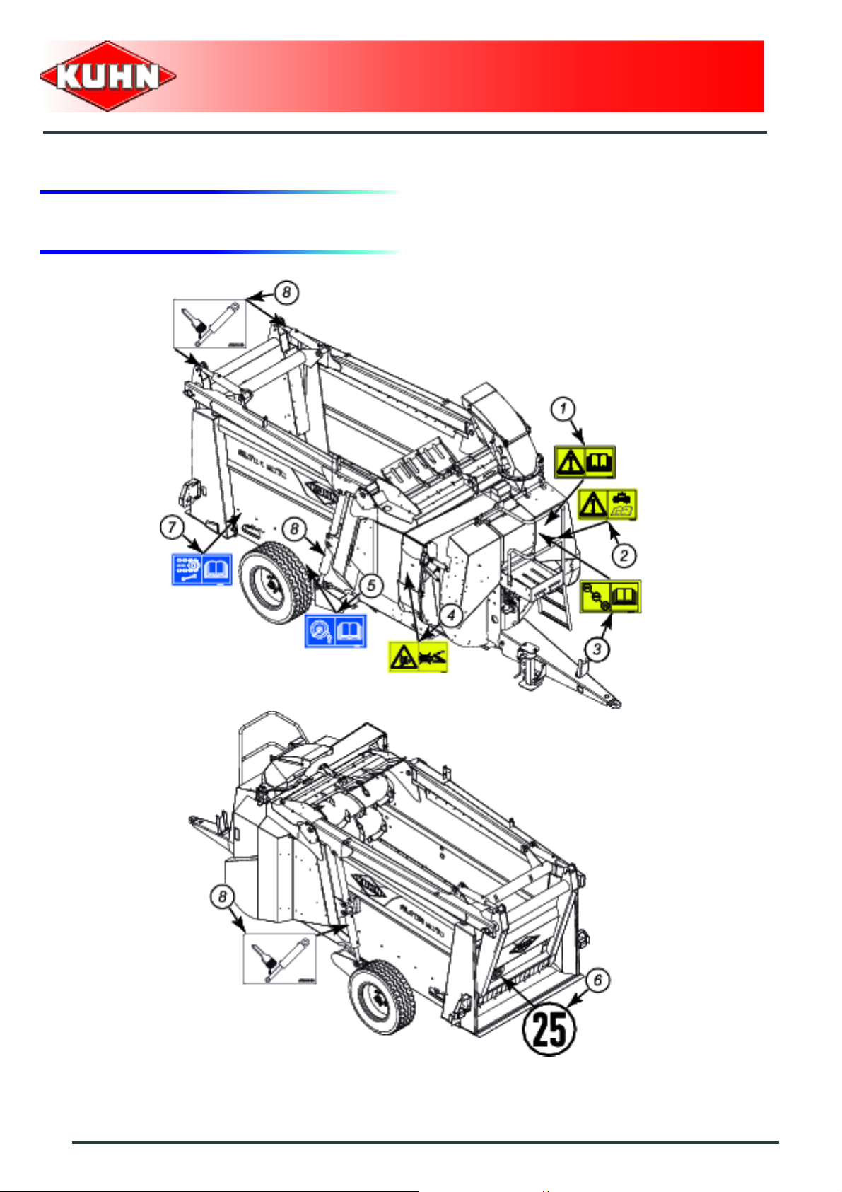
3. Location and description of safety decals on the machine
Silo unloader - Straw Spreader
ALTOR 6070
18
Safety
Page 21
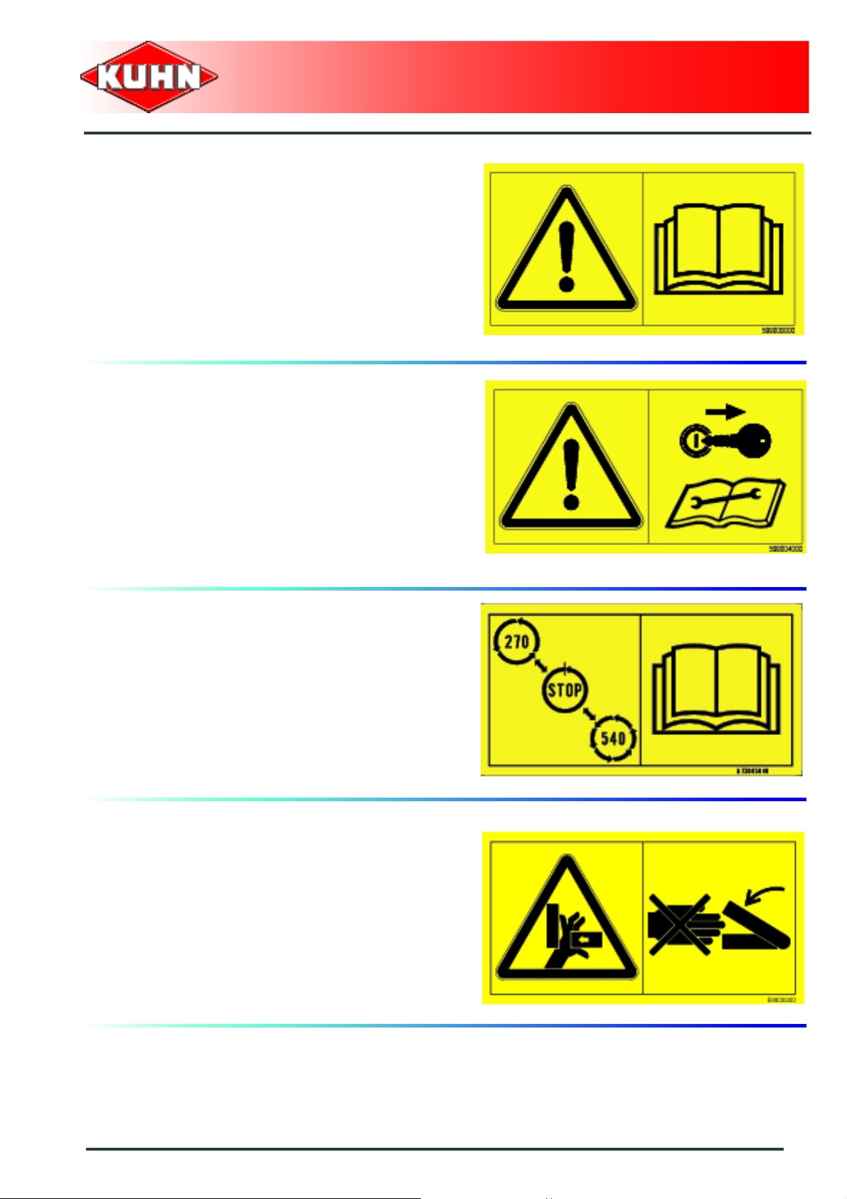
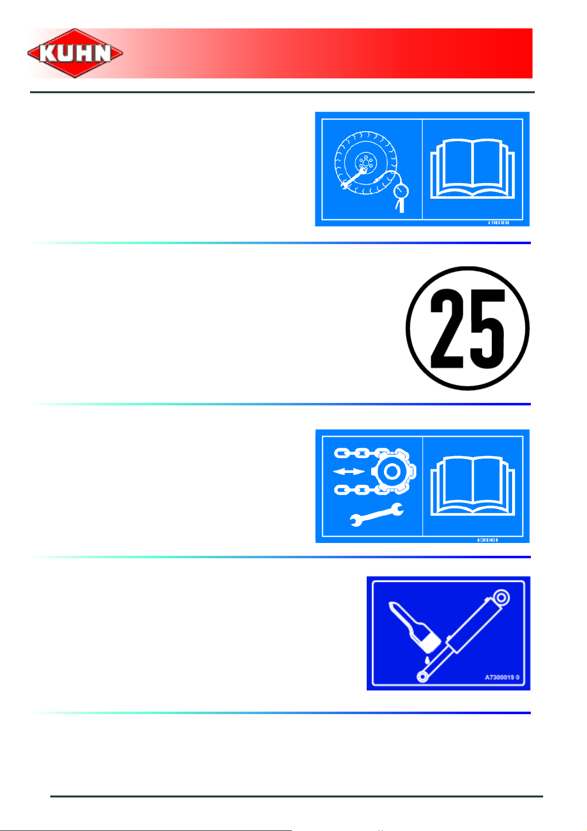
Description of safety decals
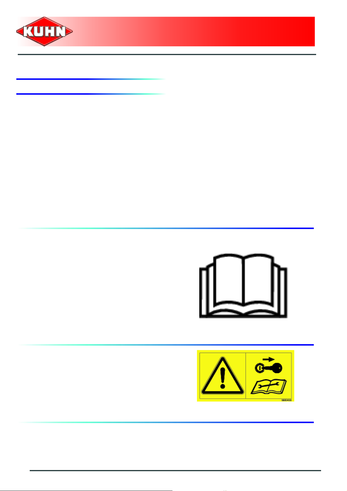
Operating instructions (1)
The operators' manual contains all the information
necessary for using the machine safely. It is imperative
to read and comply with all instructions.
Working on the machine (2)
Before leaving the tractor or before adjusting,
maintaining or repairing the machine, disengage the
PTO drive, turn off the engine, remove ignition key and
wait until all moving parts have come to a complete stop
and apply park brake.
Silo unloader - Straw Spreader
ALTOR 6070
You must totally stop the machine before changing speed (3)
Crushing area (4)
Never operate in an area where there is a crushing risk
before all moving parts have come to a complete stop.
Safety
19
Page 22
Tire pressure (5)
Check the fixing of the wheels and the tire pressure
regularly.
Speed (6)
Always keep to the legal speed limit of 25 km/h for
driving a tractor-machine assembly on public roads.
Silo unloader - Straw Spreader
ALTOR 6070
Conveyor chain tension (7)
Check the tension of the conveyor chains regularly.
Greasing the cylinder rod (8)
Grease the cylinder rods in contact with the outside.
20
Safety
Page 23
4. Road safety equipment and recommendations
The road safety equipment is mounted in the factory or
by your authorized Kuhn dealer according to current
safety regulations. Always keep to the legal speed limit
for driving a tractor-machine assembly on public roads .
Whatever the speed, we recommend, for everyones'
safety, not to exceed a maximum speed of 25.
- The lighting consists of:
• 2 Tail lights
• 2 reflective triangles (2)
Silo unloader - Straw Spreader
ALTOR 6070
Safety
21
Page 24
$Machine specifications
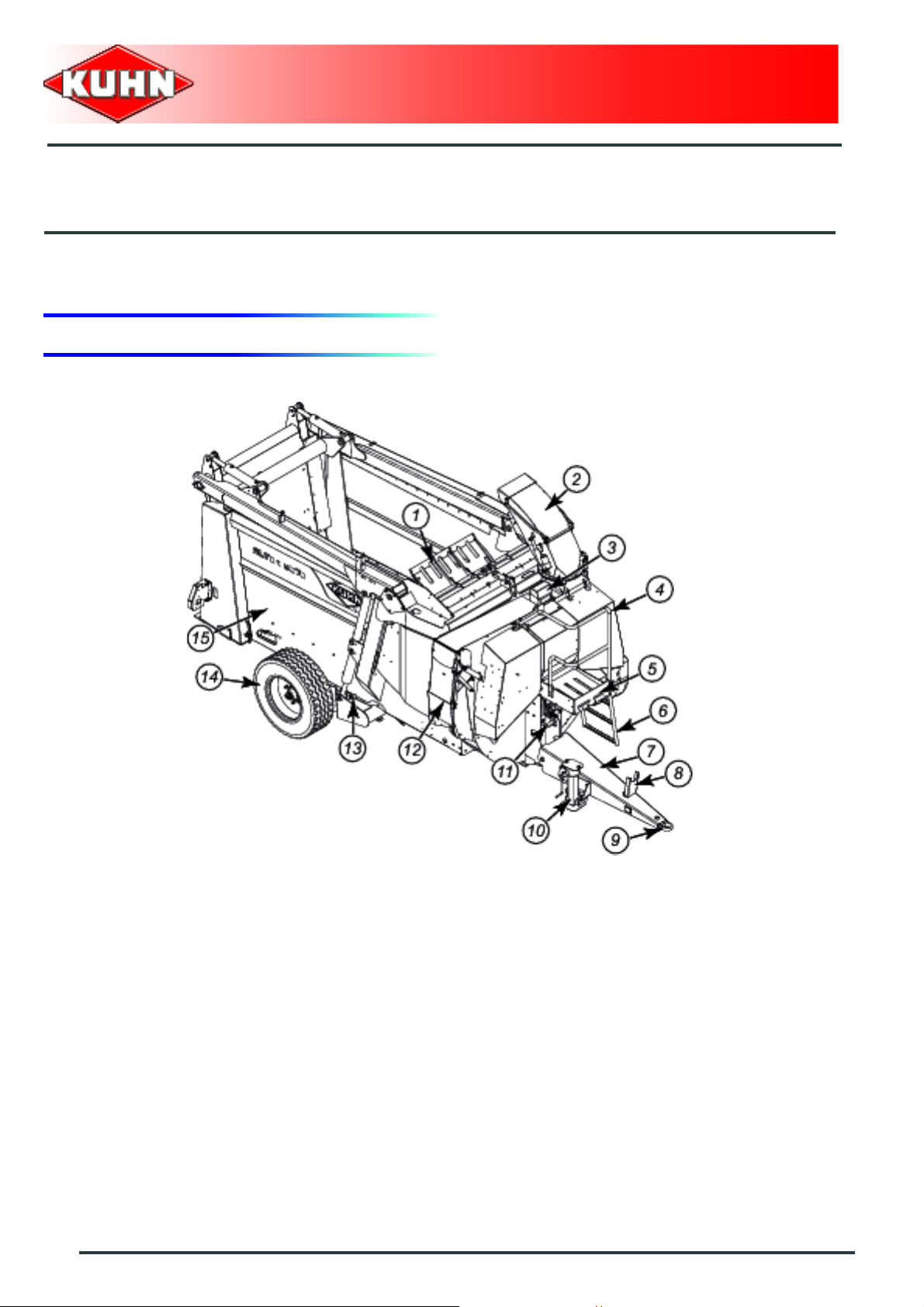
1. Description and glossary
0
Silo unloader - Straw Spreader
ALTOR 6070
1 : Deflector 2 : Swivel chute
3 : Walkway with dual control 4 : Hand rail
5 : Platform 6 : Ladder
7 : Drawbar 8 : Drive shaft support
9 : Towing eye 10 : Parking stand
11 : Gearbox 12 : Discharge chute
13 : Axle 14 : Wheel
15 : Body
22
Machine specifications
Page 25

Silo unloader - Straw Spreader
ALTOR 6070
0
1 : Bale separator 2 : Hook cylinder
3 : Hook 4 : Hook scraper
5 : Rear lights 6 : Body cylinder
7 : Arm cylinder
Machine specifications
23
Page 26
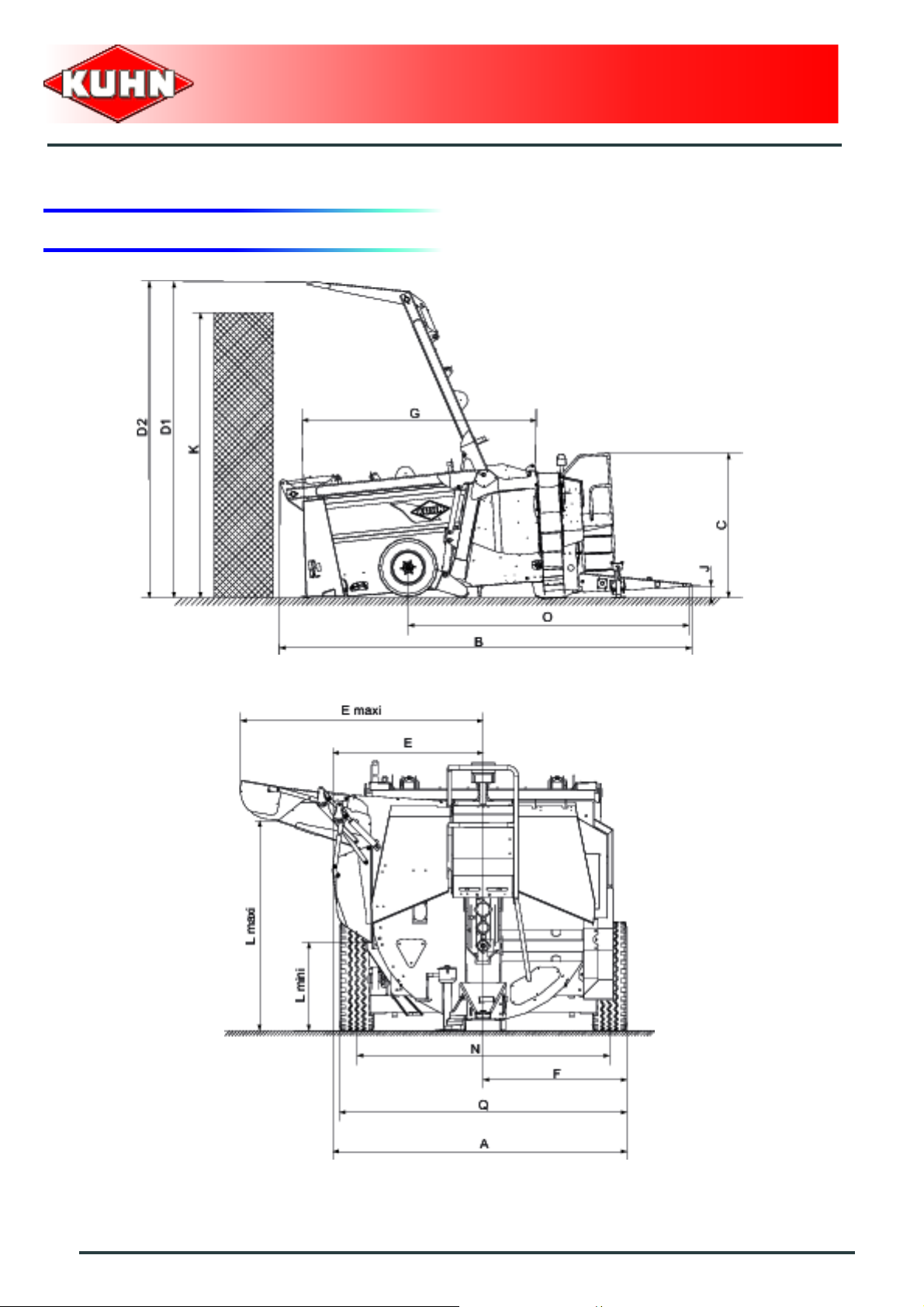
2. Technical specifications
Silo unloader - Straw Spreader
ALTOR 6070
24
Machine specifications
Page 27

Silo unloader - Straw Spreader
ALTOR 6070
Ref. Description ALTOR 6070
A Overall width 2,42 m (7’11’’)
B Overall length on the machine on the ground 6,25 m (20’6’’)
C Overall height with machine on the ground 2,22 m (7’3’’)
D1* Maximum height of the machine on the ground 4,81 m ( 15’9’’)
D2* Maximum dimensions with axle at highest setting 5,64 m (18’6’’)
E Lateral offset on chute side (closed) 1,24 m (4’1’’)
E Lateral offset on chute side (maximum) 2,00 m (6’7’’)
F Left lateral offset 1,18 m (3’10’’)
G Length inside body 3,57 m (11’9’’)
H Width inside body 1,50 m (4’11’’)
I Height inside body without arms 1,32 m (4’4’’)
Height inside body with arms 1,52 m (5’)
J Min. height of coupling 0,04 m (0’2’’)
K
L* Distribution height:
M Recommended maximum silage unloading height 3,38 m (11’1’’)
N Track 2,06 m (6’9’’)
O Wheelbase 4,25 m (13’11’’)
P Height in transport position 2,66 m (8’9’’)
Q Width at wheels 2,36 m (7’9’’)
Maximum height of silage unloading with the machine on the
ground
Minimum 0,73 m (2’5’’)
max. 2,29 m (7’6’’)
Unloaded weight in working order 3960 kg (8730 Lb)
Weight on the axle:
4.40 m (14’5’’)
Unladen 3080 kg (6790 Lb)
Maximum 4800 kg (10582 Lb)
Weight on the ring:
Unladen 880 kg (1940 Lb)
Maximum 910 kg (2006 Lb)
Total loaded weight 5710 kg (12588 Lb)
Machine specifications
25
Page 28

Silo unloader - Straw Spreader
ALTOR 6070
Ref. Description ALTOR 6070
Capacity 6,5 m3 (230 cu.ft)
Working load 1750 kg (3858 Lb)
Tyres 285 x 70 R 19.5
Tyre pressure 6,5 bar (94 psi)
Minimum drawbar power 65 hp / 48 kW
Minimum drawbar power with belt 80 hp / 59 kW
Traction pressure required:
Minimum 170 bar (2466 psi)
Maximum 190 bar (2756 psi)
Minimum tractor output: Machine without hopper 30 l/mn (8 gal/mn)
Minimum tractor output: Machine with hopper 45 l/mn (11 gal/mn)
Maximum tractor output 60 l/mn (16 gal/mn)
Optional equipment
Mixing hopper
Loading height with machine horizontal 1,55 m (5’1’’)
Loading height with machine on the ground 1.42 m (4’8’’)
Overall length of the machine with hopper 6.25 m (20’6’’)
Swivel chute
Height of machine horizontal, with chute retr acted 2.66 m (8’9’’)
Height of machine horizontal, with chute not retracted 2.93 m (9’7’’)
Hydraulic unit
Flow 45 l/mn (11 gal/mn)
Tank capacity 60 L (16 gal)
* Depending on the tractor. (Take account of the lift
height)
26
Machine specifications
Page 29

Silo unloader - Straw Spreader
ALTOR 6070
3. Sound levels
Sound levels have been measured in accordance with th e me as ur ing meth od s as de fin ed in:
NF EN 1553 "Agricultural machinery - Self-propelled, mounted, semi-mounted and trailed - Common
safety recommendations"
Weighted equivalent continuous acoustic pressure level at the driver's seat (closed cabin) L (A) eq:
Tractor only: 68,1 dB (A)
Tractor + machine: 73 dB (A)
Machine specifications
27
Page 30

$Putting into service
1. Description of control elements
ELECTRICAL CONTROLS
For standard machines and adjustable chute
Silo unloader - Straw Spreader
ALTOR 6070
Machine with hopper
28
Putting into service
Page 31

Box On/Off switch (A)
Active controls with working light (1)
Controls in neutral (0)
Controls active (2)
Raising / lowering the arm and body (B)
Silo unloader - Straw Spreader
ALTOR 6070
Arm raising
Arm lowering
Raising the body
Lowering the body
Putting into service
29
Page 32

Raising / lowering the distribution chute and opening / closing the hook (C)
Raising the chute
Lowering the chute
Silo unloader - Straw Spreader
ALTOR 6070
Opening the hook
Closing the hook
30
Putting into service
Page 33

Beater bar On/Off (D)
Beater bar clutch engaged
Silo unloader - Straw Spreader
ALTOR 6070
Beater bar clutch disengaged
The beater bar clutch is hydraulically controlled.
Hold the lever in the required position for a few
moments until the beater bar is fully engaged or
disengaged. The green control indicator lights up
when the beater bar is fully engaged.
Conveyor forward/reverse (E)
Conveyor in forward motion
Conveyor in reverse
The conveyor only works in forward motion when
the bale separator is in fully engaged position.
Putting into service
31
Page 34

Adjusting the conveyor speed (F)
The speed is adjusted by a knob graduated from 0 to 10.
Position 0 corresponds to zero conveyor speed.
The conveyor speed is not exactly proportional to the
graduation.
The conveyor movement indicator is at the front
of the machine, on the right, just under the
distribution chute.
Silo unloader - Straw Spreader
ALTOR 6070
Deflector (G)
Regulator in low position (hay, wrapped)
Regulator in high position (recyclin g, silage distribution,
straw spreading)
32
Putting into service
Page 35

Flap closing the swivel chute and for recycling (H)
Position of distribution chute
Position of adjustable chute
Flap installation is hydraulically controlled.
This maneuver takes several seconds, so
hold the lever in the required position for a
few moments.
Silo unloader - Straw Spreader
ALTOR 6070
Electrical controls for optional equipment
Swivel chute controls
Raising / lowering the cap (I)
Raising the deflector
Lowering the deflector
Rotating the swivel chute (I)
Rotating to the left
Rotating to the right
Putting into service
33
Page 36

Mixing hopper controls
Mixing screw rotation (J)
- The lever is at top right, the conv eyor-bale separator
is running alone in forward gear.
- The lever is at bottom right, the conveyor-bale
separator is running alone in reverse.
- The lever is at bottom left, the conveyor-bale
separator is running in reverse and the mixing screw
is working.
- The lever is at center left, the mixing screw is running
alone.
- The lever is at top left, the conveyor-bale separator is
running in forward gear and the mixing screw is
working.
Silo unloader - Straw Spreader
ALTOR 6070
Adjusting the injection speed (K)
- The speed is adjusted by a knob graduated from 0 to
10.
- Position 0 is for 0 injection screw speed.
The output at the injection screw exit is not
absolutely proportional to the graduation.
Calibration by product type may be necessary.
See the mixing hopper instructions supplied with
the machine.
34
Putting into service
Page 37

Walkway electric controls
Raising / lowering the arm and body (B)
Arm raising
Arm lowering
Silo unloader - Straw Spreader
ALTOR 6070
Lowering the body
Raising the body
Opening / closing the hook (C)
Opening the hook
Closing the hook
Putting into service
35
Page 38

Changing the blower speed
The speed change lever is at the front of the machine.
The lever has three positions (for a PTO speed of 540
-1
min
):
- 0: Loading using a machine fitted with a hydraulic unit.
-540 min
-270 min
-1
: straw blowing
-1
: feeding
Follow this procedure to change gear:
• Stop the tractor PTO.
• Set the lever to the required position.
• Engage the power takeoff gently until the new gear
can be engaged.
Silo unloader - Straw Spreader
ALTOR 6070
36
Putting into service
Page 39

2. Coupling and uncoupling
Before hitching the machine, make sure that
there is sufficient ballast on the front axle of
the tractor.
Ballast may need to be added to the front of
the tractor at the right place and in
conformity with the tractor manufacturer's
recommendations. The front axle load must
not be below 20 % of the tractor's tare.
Silo unloader - Straw Spreader
ALTOR 6070
Hooking up the machine for use on the
public highway
- Position the linkage ring at the desired height using
the leg.
- Reverse the tractor and raise the leg after coupling.
- Lock the linkage with the system provided.
- Connect the linkage rupture cable to a fixed point on
the tractor frame using a quick-release link.
Hooking up the machine to be used
exclusively inside the farm
- Mount the hitch bar (1) on the lift arms (3) of the
tractor.
- Lock the drawbar (1) with clip pins 8 mm (2)
- Reverse the tractor until the coupling ring is opposite
the hole through which the drawbar passes.
- Reinstall and lock pin.
- With the machine coupled, stabilize the drawbar
laterally with the device provided for the purpose (rod,
chains, chocks...).
Putting into service
37
Page 40

Machines equipped with a weighing system
with this type of coupling, when turning
tightly, don't catch the coupling bar (or lifting
arms) against the drawbar: there is a strong
risk of damaging the tongue weight indicator.
Silo unloader - Straw Spreader
ALTOR 6070
38
Putting into service
Page 41

Setting the coupling drawbar
Adjusting the drawbar allows you to position the body at
the desired level no matter which tractor is used.-
For a good mixture, the back of the body must be
slightly lower than the front.
- Adapt the height of the drawbar to the tractor used as
follows:
• 6 height settings are possible for 2 positions of the
drawbar support plate (4) et (5).
• Dismantle the drawbar by removing shaft (6).
• Loosen the 8 bolts (7) and (8) on each side of the
drawbar (24 wrench).
• Set plates (4) and (5) in the desired position.
• Reinsert the bolts (7) (8) in the holes required
(torque 29 daNm.
• Raise the drawbar.
• Reinstall shaft (6).
Silo unloader - Straw Spreader
ALTOR 6070
To change from position (A) to position (B), or
the revers, rotate the drawbar (4) (5) support
plates by 180°. Reverse the two plates: put the
right hand plate on the left and the left ha nd plate
on the right.
The different coupling height s according to the
position of the drawbar support plate: position
(A) or (B) and orifices (1) (2) or (3) are given for
standard wheels.
Putting into service
39
Page 42

Positioning the controls
In the case of electrical controls, the unit can be placed
where the user wants in the cab.
The gear lever can be pl aced on the tractor or on the
machine.
Silo unloader - Straw Spreader
ALTOR 6070
40
Putting into service
Page 43

3. Walkway with dual control
The walkway provides users with optimal visibility of the
working surface during silage unloading, no matter what
type of tractor or machine equipment is being used.
The base control recall makes loading operations easy
(arms, hook, body).
Operating tips
- Set the machine in silage unloading position.
- Before climbing onto the walkway:
• Check the machine for proper oil supply.
• Make sure that nobody can use the main controls in
the cab.
Silo unloader - Straw Spreader
ALTOR 6070
For safety reasons, climb down from the
walkway when the machine is being moved.
It is strictly forbidden to carry personnel on
the walkway.
To protect the walkway dual electric cont rols, close the
lid of the control box after each use.
Putting into service
41
Page 44

4. Swivel chute
The maximum distance of straw spreading with the
swivel chute is 13 m (4’3’’).
The swivel chute is indispensable in buildings with a
single central alley and only one entrance.
The wide rotation angle makes it possible to work in all
directions without blowing the product onto the tractor
cab.
The straw blowing device can be used on the right or the
left.
Silo unloader - Straw Spreader
ALTOR 6070
The distance of straw spreading is controlled from the
cab via an electric cylinder.
To avoid any error during handling and incorrect use of
the chutes, do not use the swival chute to distribute
wrapped grass.
The machine is equipped with a flap position indicator.
Before moving the arm, the adjustable chute
must be positioned to avoid any risk of
collision with the arm.
42
Putting into service
Page 45

5. Mixing hopper
The mixing hopper with a volume of 575 L (151.9 gal)
can be used to add minerals and concentrate to rough
fodder (grass or maize silage...).
Incorporation takes place in the turbine.
With its extra low profile and two side filler hatches,
loading takes place with no particular accessories.
For maximum accessibility, position the machine on the
ground and lower the tractor lifting mechanism as far as
possible when the machine is coupled to the hitching
bar.
Silo unloader - Straw Spreader
ALTOR 6070
Putting into service
43
Page 46

Hydraulic connections
To use the machine with a tractor with a hydraulic output
in excess of 60 l/min (15.9 gal/min) ; a flow divider must
be fitted to prevent the circuit overheatin g.
If your tractor is fitted with a closed-center
hydraulic circuit, make a return to the filter.
Machine without a hydraulic system
In order to power the machine's independent distributor,
the machine can be connected to the tractor hydraulics
in one of three ways:
1. Connection to a single-acting control valve and
direct return to the tank.
2. Connection to a double-acting distributor. The first
port is used to connect the pressure hose and the
second for the return hose. On fitting, make sure
that the direction of the oil flow is correct..
3. Connection to a line from the tractor.
Silo unloader - Straw Spreader
ALTOR 6070
- For maximum user-friendliness, the original hydraulic
distributor on the tractor must be equipped with a
continuous pumping position.
- The operating pressure of the hydraulic circuit is 190.
- The minimum and maximum hydraulic oil flow for a
standard machine is 30 l/min (7.9 gal/min) and
60 l/min (15.9 gal/min) respectively.
- The pressure and return hoses are fitted with a male
push/pull coupler (ISO 7241).
- The pressure hose has a white arrow on a red
background (1), pointing from the tractor to the
machine.
- The return hose (2) is marked by a white arrow on a
blue background, pointing from the distributor toward s
the tractor.
44
Putting into service
Page 47

Before connecting, make sure that the couplers are
clean. The plastic caps MUST be used when the
machine is not hitched to the tractor.
After connecting the hoses, check that there
is no risk of catching them during operation.
When the machine is not hitched to the tractor, all
hydraulic hoses must be put back in the special support.
Machine with hydraulic power unit
Optional equipment
This option makes the machine independent of the
tractor hydraulic circuit: no hydraulic connection to be
made before using the machine.
Silo unloader - Straw Spreader
ALTOR 6070
Putting into service
45
Page 48

Electrical connections
Lighting
Connect to the standardized 7-pin socket located at the
back of the tractor.
Control and Weighing Unit Power Supply
On tractors equipped with a 3 terminal female connector
in accordance with the standard DIN 9680A, connect the
control and weighing unit directly.
For other tractors, a harness to be connected directly to
the battery is delivered with the machine.
The wiring harness is fitted with a 15 Amp ATO type
fuse.
Silo unloader - Straw Spreader
ALTOR 6070
To use the machine with another tractor, a
second tractor-side power harness can be
ordered under p/n A7040170.
Control box Harness on tractor side
Machine Fuse type ATO Fuse 30 A Harness references
6070 Standard 15 A 83233017 83233020 A7040170
6070 Adjustable chute 20 A 83233018 83233020 A7040170
6070 Mixer hopper 15 A 83233017 83233020 A7040170
46
Putting into service
Page 49

PTO shaft
Make sure that the PTO shaft is correctly
adjusted, to avoid premature wear and tear.
Separate the two half PTO shafts and connect them to
the machine's input shaft and to the tractor PTO stub.
Check the length of the PTO shaft:
- Check the maximum overlap when the machine is in
transport position and the tractor turned to the
direction which provides maximum overlap.
- When the PTO shaft is in its maximum overlap
position (retracted), tubes should not butt against the
yokes. As a safety measure, a clearance (L) of at least
25 mm (1’’) must be maintained.
- When the PTO shaft is in its maximum extended
position, the tube overlap must be more than
330 mm (13’’)
Silo unloader - Straw Spreader
ALTOR 6070
If this is not the case:
• Mark length (H) to cut when the transmission is the
maximum overlap position.
• Shorten the guard tubes and the transmission tub es
by the same length.
• Bevel and clean the tubes.
• Grease the inside of the outer tube.
Check that there is still a minimum overlap of
330 mm (13’’) when the machine is in working
position and the tractor in line with the machine.
- The cardan drive shaft must not work at an angle X:
• More than 15° for a standard joint
• More than 25° for a homokinetic joint.
Putting into service
47
Page 50

To avoid serious accidents, the PTO drive
shaft guards must be properly in place and
fixed with the chains provided.
Attach PTO shaft guard chain in hole (1) on machine
side.
Immediately replace any worn or damaged
guard.
Silo unloader - Straw Spreader
ALTOR 6070
48
Putting into service
Page 51

$Instructions for transport
1. Conformity with the road regulations
Before driving the machine on public roads,
ensure that the machine complies with
current highway code regulations.
Check that the braking and lighting systems are in good
condition.
Silo unloader - Straw Spreader
ALTOR 6070
Instructions for transport
49
Page 52

Before placing the machine in working
position:
Check the immediate surroundings before
starting up the machine. Make sure that the
visibility is adequate and that there are no
obstacles in the machine working area.
1. Preliminary checks
Silo unloader - Straw Spreader
ALTOR 6070
$Instructions for work
Carry out the following checks before using the machine:
- Check the wheelnuts and tighten them if necessar y to
25 daNm (184.39 Lb.ft) daNm.
- Check the tension of the conveyor chain and adjust it
if necessary.
- Check that the screws and nuts are tightened,
including the ones that fix the tools (knives, conveyo r
bars).
- When the distribution is finished.
- Grease all moving parts. Use only lubricants
recommended by the manufacturer.
- Check the oil level in the gearbox.
- Check the oil level in the conveyor gearbox.
- Check the oil level in the hydraulic unit and the
cleanliness of the oil filter (optional).
50
Instructions for work
Page 53

2. Functional check, no load
Before using the machine for the first time
with a load, make sure that the tractormachine combination is in working order.
Make sure there are no foreign bodies inside
the machine.
- Make sure you can change PTO speed. (Caution: this
is not synchronised).
- For a machine with a hydraulic unit, check whether the
gearbox can be set to neutral.
Silo unloader - Straw Spreader
ALTOR 6070
- Select a PTO speed (270 m i n
- Align the tractor and the machine, then engage the
PTO drive and leave the tractor idling.
- Gradually increase the engine speed until the PTO
reaches 540 min
- Start the beater bar then the conveyor (test in both
directions).
- Now check that the machine is running smoothly and
free from vibration.
- Reduce the engine speed once again until it is idling.
If the machine is noisy or vibrating abnormally,
stop the PTO immediately and refer to the
troubleshooting section or contact your Kuhn
dealer. When the problem has been solved, start
the test procedure again from the beginning.
-1
.
-1
or 540 min-1).
Instructions for work
51
Page 54

- Operate the hydraulically-controlled elements and
check that the machine is functioning properly.
- Stop the PTO, switch off the control unit and switch off
the tractor engine.
If one of the hydraulic functions is not working, or
is running in the wrong direction, check the h ose
connections and start the test procedure again
from the beginning.
- Test the operation of the lighting and signalling
system (sidelights, brake lights and indicators).
Precautions and prevention of fire risk
Your machine works with moving parts (bale
separator(s), turbine) and highly inflammable products.
There is therefore a real risk of fire resulting from:
- Overheating of the power takeoff friction limiter.
Please do not use this limiter excessively. If smoke
issues from the transmission, stop the machine
immediately and leave the limiter to cool outside the
buildings.
- Winding strink or products at the ends of the bale
separator(s). Each time, before using the machine,
check the ends of the bale separator(s) to remove
products which have become wound round or have
accumulated in this area.
- Worn bearing. Grease bearings regularly and check
their condition.
- Sparks caused by pebbles or metal objects in the
straw.
Silo unloader - Straw Spreader
ALTOR 6070
It is highly recommended to have an extinguisher which
has been checked and maintained, on your tractor.
Recommended types: sprayed water + additive, ABC
powder.
It is strictly prohibited to use your machine stationary
inside a building.
52
Instructions for work
Page 55

3. Silage unloading
For a machine equipped with a hydraulic unit,
you must set the gearbox to neutral..
Approaching the silo
- Set the hydraulic distributo control to continuous
pumping mode.
- Raise the arm and the hook as far as possible to
ensure good visibility and avoid crushing the heap
following a collision.
Silo unloader - Straw Spreader
ALTOR 6070
- Lower the machine as far as it will go, taking care to
avoid scraping the heel along the ground, then
reverse towards the front of the silo.
- Set the heel of the machine on the ground before
contacting the silage to be unloaded.
For a corridor silo, position the machine slightly on the
bias so as to load as close to the wall as possible.
Never attempt to penetrate the silo by
reversing forcefully.
Instructions for work
53
Page 56

Loading the machine
Always start unloading the product from the top.
- From the tractor cab or walkway, position the hook so
as to take the product over a depth of about 40 cm
(1’4’’).
- Move the hook in a to and fro movement while
lowering the arm gently.
- When the hook is down, take it inside the body while
raising the arm to ensure proper filling.
- Raise the arm with the hook retracted and repeat the
loading operation until the machine is properly filled.
Silo unloader - Straw Spreader
ALTOR 6070
- At the end of loading, set the hook in the position of
rear door without compressing the product against the
bale separator.
Never compress the product against the bale
separator.
54
Instructions for work
Page 57

4. Loading bales
For a machine equipped with a hydraulic unit,
you must set the gearbox to neutral..
Round bales
- Raise the arm and hook for good visibility.
- Reverse the machine near to the bale.
- Extend the hook as far as possible and lower the arm
until it comes into contact with the bale and covers it.
Silo unloader - Straw Spreader
ALTOR 6070
- Keep the arm in contact with the bale while reversing
slowly. Once the bale is engaged in the body, finish
loading with the hook and arm.
- Raise the back of the machine to hold the bale in the
body.
- Raise the arm slightly to decompress the bale.
- Remove the binding, then lower the arm again.
To make it easier to spread the hay or straw with
a round bale, load the bale so that it can unroll
naturally. This allows the blower-beater bar
assembly to be fed more easily, and improves
the straw blowing or feeding.
Instructions for work
55
Page 58

Rectangular bales
- Raise the arm and hook for good visibility.
- Reverse the machine near to the bale.
- Extend the hook as far as it will go and lower the arm
until it contacts the middle of the bale.
- Keep the arm in contact with the bale while reversing
slowly. Once the bale is engaged in the body, finish
loading with the hook and arm.
- Once the bale is loaded into the machine, position the
hook to hold it in place without compressing it against
the bale separator.
Silo unloader - Straw Spreader
ALTOR 6070
- Raise the back of the machine to hold the b ale in the
body.
- Raise the arm slightly to decompress the bale.
- Remove the binding, then lower the arm again.
It is easier to remove the bindings when the bale
has been loaded with the bindings on the side.
- Position the hook so that the marker rod fits into the
notch.
56
Instructions for work
Page 59

5. Adjustment setting
The product adjustment system, place above the 2 bale
separators and at the turbine inlet, has 2 working
positions:
Low position:
- Used to adjust and split the product.
This position is mandatory for distributing
wrapped bales and hay.
Silo unloader - Straw Spreader
ALTOR 6070
High position:
- Leaves a maximum inlet for the product in the turbine.
This position is recommended for silage and
straw distribution.
Instructions for work
57
Page 60

6. Distribution
Select the blower speed for feeding: 270 min-1.
Always start the tractor PTO before engaging the
beater bar. Stop the beater bar be fore stopping
the PTO. If you do not do this in the right order,
you are very likely to block up the blower.
The distribution chute on the right of the machine is used
for 2 purposes.
For optimal quality of work and product positioning in the
designed place, the distribution chute cap can be set to
three positions.
Silo unloader - Straw Spreader
ALTOR 6070
For easy manual adjustment of the position, open the
chute halfway.
Pull the handle down.
Put the spindle into the desired notch (the most external
one sets the cap to the greatest angle of tilt).
Operating tips:
To stop the distribution (posts, obstacles) disenga ge the
beater bar. (The conveyor stops at the same time).
To avoid clogging the machine in difficult conditions,
watch the engine speed carefully. Slow down conveyor
speed or even reverse the direction if the engine speed
drops or the belt starts to slip. If it becomes overloaded,
allow it to empty before making the conveyor move
forward again.
58
Instructions for work
Page 61

Never attempt to clear the product by hand or
with a tool (fork, etc.) while the machine is
running.
If the blower or bale separator is blocked, use
the hook (1) inside the left hand machine
casing, to remove any product which is stuck
in the distribution chute or bale separator.
Afterwards, use a lever to turn the blower
freely.
Silo unloader - Straw Spreader
ALTOR 6070
When the machine is loaded, we strongly
advise you to not leave the conveyor running
in reverse longer than is necessary.
Before starting the beater bar, make sure the conveyor
speed is set to position 0 to prevent a load being fed into
the blower.
The product flow rate is adjusted by:
• Changing the tractor engine speed: this regulates
the hydraulic flow and the PTO rotation speed.
• The conveyor speed.
Instructions for work
59
Page 62

Silage distribution
- Start up the tractor PTO and bring the engine up to
nominal speed.
- Switch the tractor's hydraulic distributor to continuous
pumping.
- Point the delivery chute downwards so that the forage
should be properly channelled to the ground or into a
trough.
- Start the bale separator by engaging it until the light
indicator comes on.
- To distribute the product, start the conveyor running
forward and adjust the speed:
• Set the conveyor to forward.
• Adjust its speed.
- Rake product regularly onto the conveyor using the
hook.
- The conveyor speed is set at the control box
according to the forward speed and product
distribution criteria and the type of product.
- When the distribution is finished:
• Retract the arm and hook as far as they will go.
• Stop the conveyor and disengage the beater bar.
• Disengage the bale separator.
• Close the distribution chute.
• Disengage tractor PTO.
Silo unloader - Straw Spreader
ALTOR 6070
To distribute light products (maize silage, food
supplements), reduce the tractor engine speed
and hence the turbine rotation speed as far as
possible to limit spraying product onto the
ground.
60
Instructions for work
Page 63

Hay and haylage
Never distribute hay or haylage with hooks fitted
to the beater bar.
- Start up the tractor PTO and bring the engine up to
nominal speed.
- Switch the tractor's hydraulic distributor to continuous
pumping.
- Point the delivery chute downwards so that the forage
should be properly channelled to the ground or into a
trough.
Silo unloader - Straw Spreader
ALTOR 6070
- Start the bale separator by engaging it until the light
indicator comes on.
- To distribute the product, start the conveyor running
forward and adjust the speed:
• Set the conveyor to forward.
• Adjust its speed.
- The conveyor speed is set at the control box
according to the forward speed and product
distribution criteria and the type of product.
- When the distribution is finished:
• Retract the arm and hook as far as they will go.
• Stop the conveyor and disengage the beater bar.
• Disengage the bale separator.
• Close the distribution chute.
• Disengage tractor PTO.
Instructions for work
61
Page 64

Operating tips
- To facilitate feeding the turbine from the bale
separator, let the bale turn freely under the action of
the separators.
- Reduce engine speed when feeding is over to limit
projections.
During feeding, raise the back of the body in order to:
• keep round bales up against the beater bar when
the product requires little power.
• facilitate the rotation of round bales against the
beater bar when the product is tougher.
- The conveyor speed is set at the control box
according to the forward speed and product
distribution criteria and the type of product.
Silo unloader - Straw Spreader
ALTOR 6070
- If you are using the equipment with 2 round bales,
make sure the first bale is turning freely before
engaging the separators. Reverse the conveyor if
necessary.
62
Instructions for work
Page 65

7. Straw blowing
Select the blower speed for straw blowing: 540 min-1.
- Start up the tractor PTO and bring the engine up to
nominal speed.
- Switch the tractor's hydraulic distributor to continuous
pumping.
- Position the distribution chute or the swivel chute
(optional equipment) so that the straw is sprayed
where you want it.
Silo unloader - Straw Spreader
ALTOR 6070
- Start the bale separator by engaging it until the light
indicator comes on.
- To distribute the product, start the conveyor moving
forward. Adjust the conveyor speed according to the
type of straw. The conveyor speed is adjusted from
the control unit. It will depend on several things: how
fast the tractor is moving, the rate of distribution and
the type of product.
- Use the hook to keep the bale in contact with the
separator.
- When the distribution is finished:
• Retract the arm and hook as far as they will go.
• Stop the conveyor and disengage the beater bar.
• Disengage the bale separator.
- Put the tractor's distributor lever back to neutral,
disengage the PTO and switch off the engine.
In certain cases, the first part of rectangular
bales tends to shoot upwards at the start of straw
blowing. The guides push the product towards
the back of the machine. For this reason it is
important not to stop the conveyor and to let the
product drop naturally to the back.
Instructions for work
63
Page 66

Operating tips
- To blow the straw regularly, the bale must remain in
permanent contact with the beater bar, but must not
be blocked too hard by the gate.
- Lift the back of the machine slightly to avoid the bale
being thrown to the back of the beater bar.
- During straw blowing, adjust the height of the body in
order to:
• keep round bales up against the beater bar when
the product requires little power.
• facilitate the rotation of round bales against the
beater bar when the product is tougher.
- To improve product feed into the blower, up to 3 hooks
can be mounted on the beater bar in place of the
sections.
Silo unloader - Straw Spreader
ALTOR 6070
Keep an angle of 120° between the hooks.
Never distribute hay or haylage with hooks fitted
to the beater bar.
You are strongly recommended to spread straw
after distributing feed to the animals: this helps
clean and dry the machine (straw absorbs silage
acids) and thereby limit corrosion of the machine
by acid attack..
To spread straw in stalls, use a turbine rotation
speed of 270 min
-1
.
64
Instructions for work
Page 67

$Optional equipment
1. Hydraulic unit
Kit no.: 1926193
The hydraulic unit can be mounted on machines
already in service.
The hydraulic unit is designed to provide the hydraulic
power needed to run the machine.
It is suitable for use with tractors of low hydraulic power,
while guaranteeing optimal operation of its functions.
Silo unloader - Straw Spreader
ALTOR 6070
Description
- Auxiliary hydraulic unit
- Driven by the tractor power take-off
- Pump 55 cm
-1
min
: 45 l/min (11.9 gal/min)
- 60 L (15.9 gal) tank with filter and level
- Circuit protected by valve calibrated to 190 bar
(2755.8 psi)
- Recommended oil: type ISO VG 46 (HV), for example:
SHELL HYDRAU PW
A slight gear noise may be heard at low
speed. Use the hydraulic unit at a minimum
power take-off rate of 300 min
Functioning
- Before starting the machine, check the oil level in the
tank.
- Connect the tractor power take-off transmission and
the pump step-up gearbox drive shaft, then lock.
- The machine must be driven at a rated power-take-off
rate of 540 min
3
, speed at a power take-off rate of 540
-1
.
-1
.
Optional equipment
65
Page 68

Silo unloader - Straw Spreader
ALTOR 6070
Under no circumstances must you use the
tractor power take-off 1000 min
-1
.
- Start the tractor, then gradually engage the power
take-off until the pump turns.
- Check that all machine functions are operational.
Make sure the pump flanges and various hydraulic
connections are tight.
- With the gear lever, the hydraulic unit can be used in
three ways:
• In neutral, without engaging the blower, for all
loading operations.
• At a blower speed of 270 min
• At a blower speed of 540 min
-1
for distribution.
-1
for straw feeding.
Maintenance
- Follow the safety regulations concerning machine
servicing.
- Check the oil level in the tank periodically. The oil level
must not fall below the upper 1/3 on the indicator.
- Change the hydraulic oil every 1500 hours.
- Replace the filter cartridge after the first 50 hours of
operation, then every 500 hours. For that purpose::
• Unscrew the cap.
• Take the filter handle and remove the filter-bowl
unit.
• To remove the filter:Turn the handle a quarter turn
anticlockwise and remove the filter from its
cartridge.
• Clean the bowl.
• Put in a new filter and lock its position, turning it a
quarter turn clockwise.
• Replace the cap and reposition the seal properly to
ensure tightness.
66
Optional equipment
Page 69

2. Leg with holes
Kit no.: 1926174
Not available in certain countries.
The height of this leg cannot be adjusted when it is
supporting the machine.
The leg is designed for users who never need to couple
the machine to the tractor eye-bolt.
Silo unloader - Straw Spreader
ALTOR 6070
3. Leg with manual holes
This optional equipment provides continuous adjustment
of the drawbar height to position the linkage and
adjustment using a pin.
Optional equipment
67
Page 70

4. Homokinetic transmission with free wheel and friction limiter
Kit no.: 1926178
The transmission can be mounted on machines already
in service.
The homokinetic transmission pr ovide s a wider angle of
displacement and free rotation of the blower.
Before using this equipment, read manual supplied with
the PTO.
Silo unloader - Straw Spreader
ALTOR 6070
5. Weighing unit
Kit no.: 1936023
This unit weighs and programs the animals' feed rations.
Read the instructions carefully before
weighing.
68
Optional equipment
Page 71

$Maintenance and storage
1. Greasing and oil change
Frequency chart
Silo unloader - Straw Spreader
ALTOR 6070
Greasing
Grease:
- Greasing points from (1) to
(17)
Draining
Oil change:
- Gearbox
- Conveyor reducing gearbox
- The hydraulic system
Maintenance
- Changing the filter cartridge in
the hydraulic unit
- Check the conveyor chain
tension
After 2 hours
After 50
hours
Every 100
hours
Every 500
hours
Every 1500
hours
33
33
33
3
33
33
- Check belt tension
- Check the gearbox level
- Verification of the level of the
conveyor reducing gearbox
- Tighten the linkage bar eyebolts
- Check that the screws and
nuts are tight, including the
ones that fix the tools (tines,
forks, blades etc.)
33
33
33
3
33
Maintenance and storage
69
Page 72

Silo unloader - Straw Spreader
ALTOR 6070
- Check that the wheel studs
are tightened to 25 daN m and
the tire pressure is 5 bars
- Check the state of wear of the
moving parts, replace them if
necessary with KUHN parts
- Clean the machine (body,
gate and chute). Avoid
splashing the electrical
components, the belt, etc.
Greasing points
After 2 hours
After 50
hours
Every 100
hours
Every 500
hours
33
3
3
Every 1500
hours
70
Maintenance and storage
Page 73

Silo unloader - Straw Spreader
ALTOR 6070
0
1 : Deflector cylinder pin 2 : Swivel chute
3 : Side chute cylinder pin 4 : flap cylinder pin
5 : Parking stand 6 : Conveyor rotation indicator
7 : Conveyor shaft 8 : Bale separator bearing
9 : Axle pin 10 : Body lifting cylinder pin
11 : Arm cylinder pin 12 : Arm pin
13 : Hook cylinder pin 14 : Hook pin
15 : Clutch release cylinder pin 16 : Clutch tension rod
17 : Small pulley bearing
Maintenance and storage
71
Page 74

Greasing
The greasing points are shown by a white picture on a
blue background.
Some greasers are situated under cases or protective
plugs.
Upon delivery, take the time to open all the cases in
order to find all the different greasing points.
Regular greasing allows the life span of the rotating parts
to be significantly increased.
Silo unloader - Straw Spreader
ALTOR 6070
Lubricant chart
Description Recommended lubricants Equivalent standard
Gearbox
Capacity 5 L (1.3 gal)
Gearbox
Capacity 1.5 L (0.4 gal)
Central hydraulic tank
Capacity 60 L (15.9 gal)
Greasing SHELL RETINAX EP 2 NLG1
SHELL OMALA 150 ISO CKC 150/ SAE 80 W 90
SHELL OMALA 150 ISO CKC 150/ SAE 80 W 90
ISO 46 SHELL HYDRAU PW SAE 15 W-40
72
Maintenance and storage
Page 75

PTO shaft
The transmission must be greased with the
"transmission in line".
Every 8 hours
• universal joints (1)
Every 20 hours
• transmission tube (2)
Silo unloader - Straw Spreader
ALTOR 6070
Every 40 hours
• guide rings (3)
• locking pins (4)
• constant velocity joint (5)
Maintenance and storage
73
Page 76

2. Checking friction limiter settings
Torque calibration is provided by the pressure of the
spring-washers on the friction disks.
- The collar (1) is used as a reference for calibrating the
limiter correctly.
- Tighten the bolts (2), until the flange (3) is in contact
with the collar (1) without blocking it:
• Tighten the bolts (2) until the collar is blocked, then
unscrew them by a quarter turn.
- The collar must not be blocked or deformed by
excessive tightening of the bolts.
Silo unloader - Straw Spreader
ALTOR 6070
Do not over-tighten the bolts because the
limiter function could be compromised.
Do not change the calibration: risk of
damaging the machine, cardan drive and
tractor.
Friction may raise the temperature, do not
touch them.
To prevent the risk of fire, do not bring
inflammable products into the area around
the friction and avoid prolonged sliding.
74
Maintenance and storage
Page 77

3. Control storage
ELECTRICAL CONTROLS
Make sure the controls are put away after every use to
protect them from the weather.
Machine without hopper
A fastening hook (1) is located under the front right
casing.
Silo unloader - Straw Spreader
ALTOR 6070
Machine with hopper
Store the control in the protective casing (1).
Maintenance and storage
75
Page 78

Walkway dual control
To protect the walkway dual electric controls, close the
lid of the control box after each use.
Silo unloader - Straw Spreader
ALTOR 6070
76
Maintenance and storage
Page 79

4. Cleaning the conveyor
The conveyor is contained in a unit to keep it clean.
Open the emptying hatch once a week to remove
product accumulated at the back of the unit.
How to proceed:
• Set the tractor distribution lever to the continuous
pumping position.
• Engage the tractor PTO and the beater bar.
• Put the conveyor into forward for a few seconds to
bring out any product accumulated at the back of the
unit.
• Stop the conveyor; disengage the beater bar then
the tractor PTO.
• Stop the tractor engine and remove ignition key.
Silo unloader - Straw Spreader
ALTOR 6070
Wait for a few moments until the machine has
completely stopped.
• Pull on the locking handles (1).
• Release the hooks holding the ring (2).
• Open the hatch as wide as possible (3).
• Use a broom or similar to remove any product left
inside.
• Raise the hatch and put the two hooks into the rings
before lifting the handles.
• Lock the hatch by lifting the handles.
Maintenance and storage
77
Page 80

5. Conveyor chain tension
Check the chain tension after every 100 hours of use.
If the arrow is over 150 mm (4’11’’) mm, tighten the
chains.
Never completely tighten the chains. Leave a
minimum play of 50 mm mm
Silo unloader - Straw Spreader
ALTOR 6070
How to proceed:
• Open the hatch (3) using the procedure described
for cleaning the conveyor.
• Loosen counter nut (1).
• Unscrew the conveyor extension nuts (4).
• Tension the unit with nuts (2).
• Tighten the counter nut.
• Tighten the conveyor extension nuts (4).
• Tension both sides of conveyor belt identically.
• Close the hatch as shown in the section on
"Cleaning the conveyor".
When the chain tension indicator has stopped, shorten
the chains (right and left) by 2 links.
78
Maintenance and storage
Page 81

6. Checking and adjusting the sections
Regularly check the position of the regulator
combs relative to the sections.
- External regulator combs (1):
• They must be centered relative to the sections
passing on each side.
- Internal regulator combs (2):
• The distance 'd'' between these regulator combs
and the sections must be less than 10 mm.
Silo unloader - Straw Spreader
ALTOR 6070
- The unbevelled side must be on th e regulator comb
side to obtain optimal product cutting.
To adjust the position of the regulator combs relative to
the sections, add or remove spacer shims (Part no.:
A5204400).
To guarantee optimum cutting, the edges of the sections
must be kept sharp. Sharpen or replace them as
necessary..
You can also swap sections around in order to use both
cutting edges of each section.
Be very careful when replacing sections. You
run a very serious risk of cutting yourself
(between the regulating tines and the
sections).
Maintenance and storage
79
Page 82

7. Belt tension
In order to guarantee optimal operation, belt tension
must be checked and adjusted if necessary every 100
hours (or more often in case of frequent feeding with
tough products).
The belt tension is adjusted using the screw rod (1) nut
(2) and check nut (3).
In the engaged position, the spring tension must be set
to L = 180 mm (7’’) (length of compressed spring).
Left side drive (lower bale separator)
Silo unloader - Straw Spreader
ALTOR 6070
80
Maintenance and storage
Page 83

Right side drive (upper bale separator)
Silo unloader - Straw Spreader
ALTOR 6070
Maintenance and storage
81
Page 84

8. Changing oil and checking levels
Gearbox
Draining:
- Remove filler plug ((1)).
- Place a container underneath the gearbox.
- Remove drain plug (2).
Filling:
- If necessary replace seal.
- Reinstall draining plug (2).
- Remove level plug (3).
- Fill the housing with a funnel via the upper hole in the
housing.
- Stop filling as soon as the oil comes out of oil level
port.
- Reinstall level plug (3).
- Reinstall filler plug (1).
Silo unloader - Straw Spreader
ALTOR 6070
Capacity: 5 L (1.3 gal) of SAE 80W90 Shell
Omala 150 oil.
82
Maintenance and storage
Page 85

Conveyor reducing gearbox
Draining:
- Remove filler plug (1).
- Place a container underneath the gearbox.
- Remove drain plug (2).
Filling:
- Reinstall draining plug (2).
- Remove level plug (3).
- Fill the container with oil.
- Stop filling as soon as the oil comes out of oil level
port.
- Replace the stoppers (1) and (3).
Silo unloader - Straw Spreader
ALTOR 6070
Capacity: 1.5 L (0.4 gal) of SAE 80 w 90 SHELL
OMALA 150 oil.
9. Tyres
Regularly check the tyre pressure : 6.5 bar (94.3 psi).
Check the tightness of the wheel studs regularly (torque
25 daNm (184.39 Lb.ft) daNm).
Maintenance and storage
83
Page 86

10. Storage
If the machine is not to be used for a long period, prepare
it for storage:
- Clean the body (inside, outside and underside).
Do not clean the cylinder rods with a
pressurized washer and detergent.
Silo unloader - Straw Spreader
ALTOR 6070
Do not direct a pressurized jet of water
towards a cylinder rod scraper seal.
- Remove any product build-up.
- Repaint any surface in danger of rusting with a special
paint.
- Grease the underbody.
- Push the cylinder rods in to the maximum to protect
them from humidity and dust.
Grease the cylinder ro ds in contact with the
outside every month.
- Clean all the greasing points and joints and grease
them.
- Park the machine under a shelter on blocks to isolate
it from damp ground.
- Check the tire pressure and that the studs are
tightened.
- Release belt tension.
84
Maintenance and storage
Page 87

11. Maintenance
Before carrying out any maintenance or
repairs on the machine, switch off the tractor
engine, remove ignition key, wait until all
moving parts have come to a standstill and
remove PTO shaft.
Before starting maintenance work involving
penetration inside the body:
Raise the machine arm and hook.
Lock the arm by setting the va lv e (2) leve r (1 )
perpendicular to the cylinder (Position A).
Silo unloader - Straw Spreader
ALTOR 6070
Don't forget to release the arm at the end of
the operation (Position B).
Maintenance and storage
85
Page 88

$Trouble shooting guide
Problem Cause Remedy
Lack of power in the hook Hydraulic problem
The hydraulic functions do not
work
The conveyor does not move
forward
Problem with hydraulics or
electrical connections or general
use.
Problem with hydraulics or
electrical connections or general
use
Silo unloader - Straw Spreader
ALTOR 6070
Make sure the hydraulic connection
between the tractor and the machine
is correct (pressure and return).
Check the hydraulic pressure
190 bar, and the pump output 35
l/min.
The return pressure must be a
maximum of 8 bar at the tractor's set
engine speed.
Check that the hoses are correctly
connected to the tractor distributor
(check that the valves open properly:
dirt can prevent correct functioning).
Check that the voltage supplied by the
battery is over 11 volts.
Check that the original tractor
distributor is in the continuous
pumping position (except for the
hydraulic system).
Check that the control box switch is in
position 1 or 2.
Check if the electrical power cable of
the control box is connected.
Check that the supply from the battery
reaches the socket.
Check the polarity of the socket.
Check that the beater bar is
completely engaged, and if you have
electrical controls, that the indicator
light is on.
Open the left side bonnet and check
that the conveyor draw roller cylinder
rod is completely in.
Check that the circuit break sensor on
the beater bar clutch is active.
Make sure that the conveyor
potentiometer is not set to 0
86
Trouble shooting guide
Page 89

Silo unloader - Straw Spreader
ALTOR 6070
Problem Cause Remedy
The sensor (1) fixed to the bale
separator clutch cylinder sets the
conveyor in motion once the bale
separator is engaged.
The clutch cylinder rod must be fully
retracted to excite the circuit-breaking
sensor
The conveyor stops during
work
The beater bar and the
conveyor stop turning during
feeding
The conveyor drive belt slips
for no obvious reason
The blower does not turn and
the friction clutch slips
Hydraulic or electric problems
Hydraulic or electric problems
Mechanical or maintenance
problem
The blower is blocked
Check there are no leaks in the
hydraulic circuit.
Check that the beater bar is
completely engaged, and if you have
electrical controls, that the indicator
light is on
Check there are no leaks in the
hydraulic circuit.
If you have electric controls, check
that the indicator is on.
Check that the clutch is totally
engaged, and that the piston rod is
right in. Otherwise, check that the
clutch cylinder is not leaking
internally.
Check that it is in good working order
and tight enough.
Disengage the tractor PTO and switch
off the engine.
Check the blower for product build up.
If necessary, use the hook fixed inside
the casing on the left-hand side of the
machine to remove any product stuck
in the distribution chute or bale
separator, then use a lever to ensure
that the turbine can turn freely. After
releasing, operate the blower with no
load for a few seconds until it reaches
normal running speed.
Trouble shooting guide
87
Page 90

Silo unloader - Straw Spreader
ALTOR 6070
Problem Cause Remedy
You can access the inside of the
blower through a hatch (1) on the left
front of the machine.
If the blower is jammed, use a tool
(releasing hook). If you start the
blower plate moving manually, you
run a serious risk of having your finger
cut off by a blade, since this system
has a very high inertia
The blower rotates, the beater
bar is engaged and the
conveyor is working but the
product does not come out
The blower bangs when the
PTO engages
The conveyor is set to 0
The beater bar is blocked
The friction limiter slips in fits and
starts
Check the conveyor speed, increase
it if necessary.
Check that the product to distribute is
not compressed against the beater
bar. Decompress the product in the
body by opening the hook slightly. Put
the conveyor into reverse for a short
time, then put it forwards again.
Engage the PTO progressively at the
recommended speed. If the tractor is
fitted with a hydraulic PTO clutch,
consult the Kuhn dealer to solve the
problem of the clutch progression for
all tractor engine speeds.
88
Trouble shooting guide
Page 91

Problem Cause Remedy
The arm descends too slowly
or too fast or the hook does
not move when the arm
descends
Silo unloader - Straw Spreader
ALTOR 6070
The speed of descent of the arm can
be adjusted via the speed limiter (1)
under the machine's left-hand casing.
The arm cylinder speed limiter is
too closed or too open
Trouble shooting guide
89
Page 92

Silo unloader - Straw Spreader
ALTOR 6070
90
Trouble shooting guide
Page 93

Silo unloader - Straw Spreader
ALTOR 6070
$Limited warranty
"KUHN-AUDUREAU S.A. B.P. 19, 85260 LA COPECHAGNIERE, FRANCE (hereinafter called ""the
Company"") warrants, in accordance with the provisions below, to each original retail purchaser of new KUHN
equipment of its own manufacture from an authorized KUHN dealer, that such equipment is, at the time of
delivery to such purchaser, free from defects in material and workmanship, providing the machine is used and
serviced in accordance with the recommendations in the Operator's manual".
This Limited Warranty covers the equip ment for a period of one year starting from the date the equipment is
delivered to the retail purchaser and during this period up to a limit of 500 hour s of use.
The date of invoice to the retail purchaser and the registration of the machine by the dealer are taken as
evidence of delivery of the machine.
This Limited Warranty covers the reimbursement (or repair) of components as well as labor charges incurred,
based on the Company warranty labor rate and allowable time for repair.
These conditions are subject to the following exceptions:
- Parts of the machine which are not of KUHN manufacture, such as tires, PTO shafts, slip clutches, hydraulic
jacks, etc. are not covered by the KUHN Limited Warranty, but are subject to the warranty of the original
manufacturer.
- Warranty claims related to the se types of parts must be handled in the same way as if they were parts
manufactured by KUHN. However, compensation will be paid in accordance with the warranty agreement of
the manufacturer concerned, in as much as the latter justifies such a claim.
- Obviously, this Warranty does not apply to failure through normal wear and tear, to damage resulting from
negligence or to faulty surveillance, to wrong use, to lack of maintenance and/or if the machine has been
involved in an accident, lent out or used for purposes other than which it was intended by the Company.
- This Limited Warranty will not apply to any product that is altered or modified in any way without the express
permission of the Company, or if parts not made by Kuhn are used on a machine sold by the Company and/or
if repairs have been carried out by anyone other than Authorized Service Dealers.
- The Company shall not be responsible for any damage to the machine or its equipment in transit or handling
by any common carrier, within or without the Warranty period.
- The Company cannot be held responsible for any claims or accidents to the owner or to any third party, nor
to any resulting responsibility.
- In the same way, the Company cannot be held responsible for paying an indemnity for whatever reason in
the case of loss of anticipated profits or of any prejudice due to a failing, a hidden fault or breakdown of the
machine.
The customer will be responsible for and bear the costs of:
- Normal maintenance of the material, i.e. gre a sing , ma inte na nce of oil levels, minor adjustments, etc.
- Labor charges due to remov ing and replac ing the faulty p art(s) or, as applicab le, the ad justme nt of th e new
replacement part(s).
- Dealer travel time, or traveling costs to and from the machine.
- Transporting machines, equipment or parts to the repair site and returning them to the user site.
- Parts defined as normal wearing items, such as belts, blades, forks, disks, knives, spades, tines, slip clutches,
etc. that are not covered by the Warranty .
Limited warranty
91
Page 94

Silo unloader - Straw Spreader
ALTOR 6070
The Limited Warranty is dependent on the strict observance of the following
conditions:
- The material must be put in service by the dealer according to our instructions.
- The machine has been registered on line via extranet - www.kuhn.com or the warranty/product registration
form has been completed and returned to the address indicated on the form as soo n as the machine has been
delivered to the retail purchaser.
- The warranty claim is completed on line via extranet - www.kuhn.com or submitted on a KUHN warran ty claim
form and and returned to the Company within one month after the date of failure or the date of problem
becoming apparent.
- Le bordereau doit être rédigé de façon lisible par le revendeur et doit obligatoirement comporter les
- informations suivantes:
• Dealer's name, address and code number
• Name and address of purchaser
• Exact type of machine
• Machine serial number
• Date of delivery to the purchaser
• Date of the incident
• Number of hours or area (hectares, acres) of use
• Power of tractor used
• Detailed description and presumed cause of the incident
• Quantity, reference number and name of the damaged parts
• Invoice number and date for replacement parts.
- The dealer should send the damaged parts to the Company address for survey report along with a copy of
the Warranty/claims form. Transport costs for the return of said parts are borne by the sender.
- The machine must be used and maintained a ccording to the instructions in the operator's manual. The quality
and quantity of lubricants used must always be in accordance with Company regulations.
- The safety measures set out in the Operator's manual and on the machine itse lf must be followed, and all the
guards and protective elements, of whatever nature, must be inspected regularly and maintained in perfect
working order.
- The judgment of the Company in all case of claims under this Limited Wa rranty shall b e fina l and conclusive
and the purchaser agrees to accept its decisions.
- If the Warranty is refused, the dealer is allowed a period of 15 days from the date of receiving o ur letter to
request the return of the damaged parts.
Further conditions: limits of application and responsibility
- This Limited Warranty shall not be assigned or transferred to anyone unless the written consent of the
Company has first been obtained.
- Persons dealing in the Company's products have no right or authority to assume any obligation or take any
decision on their behalf, whether expressly or tacitly.
- Technical assistance given by the Company or its agents for repairing or operating materi al does not lead to
any responsibility on their behalf and cannot under any circumstances bring novation or derogation to the
conditions of the present Limited Warranty.
- The Company reserves the right to change its machines without prior notice and without being obliged to
apply these changes to machines that are already sold or in service.
- Moreover, because of the constant progress in technology, no guarantee is given to the descriptions of
equipment published in any document by the Company.
- The present Limited Warranty excludes any other responsibility, whether legal or conventional, express or
implied, and there are no warranties extending beyond those defined herein.
92
Limited warranty
Page 95

Page 96

 Loading...