

Page 1
ASSEMBLY / OPERATORS MANUAL
MOWER CONDITIONERS
ALTERNA 400 / 400 R & 500 / 500 R
No 95105 D.GB - 01.2002
Page 2

DEAR OWNER,
In buying a KUHN machine you have chosen wisely. Into it have gone years of thought,
research and improvements. You will find, as have thousands of owners all over the world, that
you have the best that engineering skill and actual field testing can produce. You have
purchased a dependable machine, but only by proper care and operation can you expect to
receive the performance and long service built into it.
This manual contains all the necessary information for you to receive full efficiency from your
machine. The performance you get from this machine is largely dependant upon how well you
read and understand this manual and apply this knowledge. Please DO NOT ASSUME THAT
YOU KNOW HOW TO OPERATE AND MAINTAIN YOUR MACHINE before reading this
manual carefully. KEEP THIS MANUAL AVAILABLE FOR REFERENCE.
Your KUHN dealer will instruct you on the general operation of your machine. He is interested
that you get the best performance possible and will be glad to answer any special questions
that may arise regarding the operation of the KUHN machine.
Your KUHN dealer can offer a complete line of genuine KUHN service parts.
These parts are manufactured and carefully inspected in the same factory that builds the
machine to assure high quality and accurate fitting of any necessary replacements.
When ordering service parts it is important that you indicate the type of machine concerned
and its serial number.
For this reason please complete the model identification plate diagram below with the required
information. This will provide you with an easy reference for future service parts orders.
ABOUT IMPROVEMENTS
KUHN is continually striving to improve its products and, therefore, reserves the right to make
improvements or changes when it becomes practical to do so, without incurring any
obligations to make changes or additions to the equipment sold previously.
Page 3

- 1 -
CONTENTS
Page
Safety notices 2 - 7
Safety decals 8 - 9
Technical specifications 10
Assembly instructions 11
Attachment to the tractor 12 - 13
Detaching the machine 14
Transport to work position 15 - 16
Work to transport position 17 - 18
Adjustments 19 - 25
Securing discs and knives 27
Inspection of knives & securing elements 28 - 29
Important recommendations 30
Lubrication 31 - 36
Optional equipment 36
Storing the mower conditioner 37
Trouble Shooting Guide 38 - 39
Hydraulic schematic 40
Electric lay out, connections and schematic 41
Seven-conductor electrical connector (for North America) 42
Limited warranty 43 - 44
Copyright 2002 KUHN S.A.
Page 4

- 2 -
SAFETY
The symbol above is used throughout this manual every time recommendations are made concerning your safety,
the safety of others, or the good operation of the machine.
These recommendations must be made known to all machine operators.
DESIGNATED USE OF THE MACHINE
The ALTERNA mower conditioners must only be used for the work which they have been designed : mowing on the
ground of hay fields, grass silage fields and improved pastures for the purpose of harvesting fodder for feeding
livestock.
The manufacturer is not held liable for any damage resulting from machine applications other than those specified
by the manufacturer.
Any use other than the designated operation is at the risk and responsibility of the operator.
Designated use of the machine also means :
- following operation, maintenance and repair recommendations given by the manufacturer ;
- using only genuine spare parts, equipment and accessories as designated by the manufacturer.
The ALTERNA mower conditioners must only be operated, maintained and repaired by competent persons who are
familiar with machine specifications and operation and are aware of any danger involved.
The operator must imperatively respect current legislation concerning :
- accident prevention,
- work safety,
- public traffic circulation.
All safety advice indicated on the machine must be strictly observed.
The manufacturer is not held liable for any damage resulting from machine modifications carried out by the operator
himself or by a third party without previous written agreement from the manufacturer.
Page 5

- 3 -
GENERAL SAFETY RECOMMENDATIONS
Before operating the machine, always ensure that tractor and machine are in accordance with work safety and road
traffic regulations.
BASIC PRINCIPLES
1. In addition to the recommendations given in this manual, legislation on work safety and accident prevention must
also be respected.
2. Advice is indicated on the machine, specifying safety recommendations in order to prevent accidents.
3. Before travelling on public roads, the operator must ensure that the machine conforms to road traffic regulations.
4. Before starting work, the operator must be familiar with all machine controls, handling devices and their
functions. Once at work, it is too late to do so !
5. The tractor must be equipped with a safety cab. Keep windows and roof hatch closed for reduced sound level
while operating the PTO driven implement.
6. Before starting up the machine and beginning work, check the surrounding area (beware of children !). Make
sure there is sufficient visibility. Keep all people and animals away from the danger zone of the machine (risk
of projection!)
7. Carrying people or animals on the machine when working or in transport is strictly forbidden.
8. Machine must only be attached to tractor using means provided and in accordance with current safety
standards.
9. When attaching or removing the machine, place the parking stand into the corresponding position.
10. Special care should be taken when attaching or removing the machine from the tractor.
11. Before attaching the machine, make sure that the maximum permitted front axle weight and gross weight of
the combination are not exceeded.
12. Do not surpass the maximum permitted length and width authorized by road traffic regulations.
13. Do not surpass the maximum transport width authorized by road traffic regulations.
14. Before transporting the machine on public roads, ensure that all legally required guards and indicators (lights,
reflectors ...) are in place and in good operation.
15. All operating controls (cords, cables, rods ...) must be positioned so that they cannot be set off accidently,
risking accident or damage.
16. Before transport on public roads, locate the machine into its transport position as instructed in this operator’s
manual.
17. Never leave the tractor seat while the machine is operating.
18. Drive speed must be adapted to ground conditions as well as roads and paths.
Always avoid abrupt changes of direction.
19. Precision steering, tractor adherence, road holding and efficient braking are influenced by the type of implement,
weight, ballast of front axle, ground or road conditions. It is therefore of utmost importance to be cautious in
every given situation.
Page 6

- 4 -
20. Be particularly cautious when turning corners, paying attention to machine overhang, length, height and weight.
21. Keep clear of the machine operating area.
22. WARNING ! Danger of crushing and shearing can exist when components are operated by hydraulic or
pneumatic controls.
23. Before leaving the tractor or before adjusting, maintaining or repairing the machine, turn off the engine, remove
ignition key and wait until all moving parts have come to a complete stop.
24. Do not stand between the tractor and the machine unless the hand brake is tight and/or stops have been placed
under the wheels.
25. Before any adjustments, maintenance or repairs are carried out, ensure that the machine cannot be started
up accidentally.
PRECAUTIONS TO BE TAKEN BEFORE OPERATING THE MACHINE
1. Do not wear loose clothing which could be caught up in moving parts.
2. Wear the individual protection equipment corresponding to the work which is planned (gloves, shoes, eye
protection, helmet, ear protectors...).
3. All operating controls (cords, cables, rods ...) must be positioned so that they cannot be set off accidentally,
causing accident or damage.
4. Before operating the machine, check the tightness of all nuts and bolts, particularly on rotating parts (blades,
tines, knives, spades ...)
5. Before operating the machine, ensure that all safety guards are firmly in place and in good condition. If worn
or damaged, replace immediately.
ATTACHMENT
1. When attaching or removing the machine from the tractor, make sure that it cannot move accidentally. (Put
wedges under the wheels).
2. When attaching the machine to tractor hydraulic linkage, ensure that diameter of link pins corresponds to
diameter of ball joints.
3. WARNING ! Danger of crushing and shearing can exist in the lifting zone of the tractor hydraulic linkage !
4. Do not stand between the tractor and the machine when operating the outer control lever of the lift mechanism.
5. Make sure that the weight applied to the tractor's draught arms does not go over the maximum weight
indicated by the manufacturer.
6. Make sure flexibility between tractor draught arms and machine drawbar is sufficient.
7. In transport, the tractor draught arms should be stabilized by the linkage to avoid stabilizer bars side to side
shifting.
8. Never operate or transport the machine with a narrow wheel track tractor.
Page 7

- 5 -
POWER TAKE-OFF
1. Only use PTO shaft supplied with the machine or recommended by the manufacturer.
2. PTO guards must always be in place and in good condition.
3. Check for correct PTO overlap when at work and in transport.
4. Before attaching or removing the PTO shaft, disengage PTO shaft, turn off engine and remove ignition key.
5. If a primary PTO shaft is equipped with a slip clutch or a free wheel, these must be fitted on the machine PTO.
6. Ensure that PTO shaft is always correctly fitted and locked into place.
7. Make sure guards are correctly in place and secured with the safety chains provided.
8. Before engaging PTO, ensure that PTO speed (rotational frequency) and direction of rotation are in
accordance with manufacturer's recommendations.
9. Before engaging PTO, keep all people and animals clear from the machine.
10. Never engage PTO shaft when tractor motor is turned off.
11. Never surpass PTO angle recommended by the manufacturer.
12. WARNING ! Rotating elements can continue turning momentarily after PTO is disengaged. Keep clear until
all rotating elements are at a standstill.
13. When removing the machine, locate PTO shaft on the supports provided.
14. Fit safety cap on tractor PTO.
15. Replace any worn or damaged PTO guards immediately.
TIRES
1. Before any work is performed on the wheels, ensure that the machine rests on the ground and is perfectly stable
so that it cannot move accidentally (put wedges in place).
2. Assembly, disassembly and repair of wheels and tires must only be carried out by competent persons who
are equipped with standardized tools.
3. Check tire pressure regularly !
Respect manufacturer’s recommendations on tire pressure.
Rotation speed ... rpm (American Measure) is also expressed in metric measure : Rotational frequency ... min
-1
.
Both units are equivalent, for example : Rotation speed 540 rpm equals Rotational frequency 540 min-1.
Page 8

- 6 -
HYDRAULIC SYSTEM
1. WARNING ! Hydraulic system is under pressure (maximum working pressure : 200 bars / 2900 psi).
2. When fitting hydraulic motors or cylinders, ensure that connections have been made correctly, as per
manufacturer’s instructions.
3. Before connecting hoses to the tractor hydraulics, ensure that tractor and machine circuits are not under
pressure.
4. It is strongly recommended that the operator marks the hydraulic connections between tractor and machine
to avoid making a wrong connection. WARNING ! Functions could be reversed (for example : lift/lower).
5. Regularly check the hydraulic hoses ! In case of normal wear, replace the hydraulic hoses every 5 years.
Damaged or worn hoses must immediately be replaced .
When replacing the hydraulic hoses, make sure to use hoses with the specifications and quality recommended
by the manufacturer of the machine.
6. Should a leak be found, take all necessary precautions to avoid accidents.
7. Any liquid under pressure (particularly oil from hydraulics) can penetrate the skin and cause severe injury. If
injured, see a doctor immediately, there could be danger of infection.
8. Before any adjustments, maintenance or repairs are carried out, lower the machine, depressurize the circuit,
turn off the engine and remove ignition key.
MAINTENANCE
1. Before checking any machine malfunction and before adjusting, maintaining or repairing the machine,
disengage PTO, turn off engine and remove ignition key.
2. Check tightness of nuts and bolts regularly. Retighten if necessary.
3. If the machine is raised, prop it up in a stable position before carrying out any maintenance work.
4. When replacing a working part, wear protection gloves and only use standardized tools.
5. It is forbidden to discard any oil, grease or filters. These must be given to waste disposal organisations to
protect the environment.
6. Disconnect power source before any work is done on the electric system.
7. Check safety guards regularly, particularly those that are subject to wear. Replace immediately if damaged.
8. Spare parts used must be in accordance with specifications and standards as defined by the manufacturer.
Use only genuine KUHN parts !
9. Before any electric welding is carried out on tractor or attached machine, disconnect generator and battery
terminals.
10.Repairs on elements under pressure or tension (springs, accumulators etc.) must only be carried out by
competent persons with standardized equipment.
Page 9

- 7 -
SPECIAL SAFETY RECOMMENDATIONS
1. Use a tractor equipped with an enclosed cab with windows made of safety glass and kept closed. It is
recommended to fit polycarbonate screens inside the tractor safety cab's side and rear windows or to install
mesh guards on the exterior of them.
2. Stay a safe distance away from the mower when discs are rotating.
3. For safe machine operation, it is imperative that cutting tools be fitted in accordance with the manufacturer’s
recommendations. Use only the tool outfit supplied with the machine.
4. Each time before using the mower, inspect condition of cutting elements (knives, discs). Replace any
missing, worn or damaged cutting elements immediately. Use only genuine KUHN spare parts.
5. To avoid creating dangerous out of balance forces, always replace missing, damaged or worn knives in
pairs.
6. When replacing knives or discs, systematically inspect their securing elements as per the manufacturer’s
recommendations.
7. Regularly inspect the disc mower’s protection cover. Worn or damaged protection covers must be replaced
immediately.
8. Protection devices (such as guards, shields etc.) are intended to prevent stones, rocks or other foreign
objects from being projected. They also prevent access to the machine’s danger zones. Therefore, it is
imperative that protection devices are put in place and properly secured each time before using the
machine.
9. Crushing and shearing zones which could cause serious bodily injury when changing the machine from
transport to work position and vice versa may exist. To prevent possible injury, be extra careful when
maneuvering and ensure that everyone is at a safe distance away from the machine.
10. Never tow the machine at speeds higher than 25 km/h (15 mph).
11. PTO drive to the mower must never be engaged unless the cutterbar skid shoes are in contact with the
ground and the protective cover is folded down.
12. Ground of the pastures to be mown must be free of foreign objects.
13. Even when the machine is used in accordance with it purpose, objects may be projected. It is therefore
imperative that everyone be kept away from the danger zone, that extra care be taken and that extra
precaution (such as safety indicators) be taken when mowing pastures alongside roads or near public areas
(parks, schools etc.).
14. Never mow in reverse.
15. When disengaging the PTO drive, moving parts continue to rotate for some time. Wait for all moving parts
to come to a complete stop before approaching the machine.
16. If an obstruction is hit, stop the tractor immediately, disengage PTO drive, turn off engine, remove ignition
key and wait for all moving parts to come to a complete stop.
Check the entire machine for any damage before resuming work.
17. It is strongly recommended to have your machine checked by your dealer after each season, especially
blades and discs and their fixing devices (nuts, bolts etc.).
Page 10
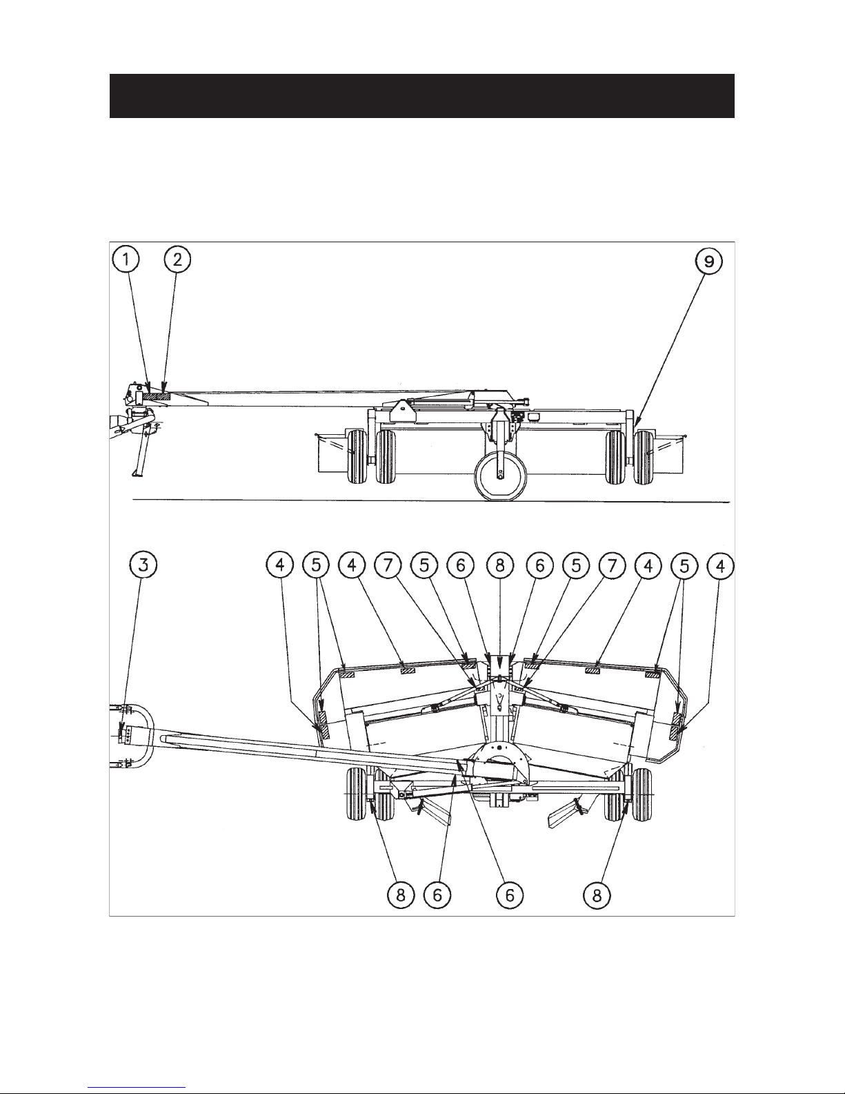
SAFETY DECALS
THE FOLLOWING SAFETY PICTORIALS HAVE BEEN PLACED ON YOUR MACHINE IN THE AREAS
INDICATED. THEY ARE INTENDED FOR YOUR PERSONAL SAFETY AND FOR THE SAFETY OF THE
PEOPLE WORKING WITH YOU. THE TEXT SHOWN ON THEM GIVES THEIR PRECISE MEANING.
ENSURE THAT THESE PICTORIALS ARE ALWAYS LEGIBLE. IF THEY ARE NOT, REPLACE THEM.
Page 11

- 9 -
4
5
8
9
6
7
3
1
2
Page 12

- 10 -
Oil capacity : Grade SAE 80 W EP (GL4)
ALTERNA 500 / 500 R Litre US pints Imp. pints
Gyrodine gearbox 6 12 10.5
Central gearbox 5.75 11.5 9.85
Cutterbar oil capacity 2 x 1.7 2 x 3.5 2 x 3
Upper central pivot gearbox 1.75 3.5 3
Lower central pivot gearbox 1.75 3.5 3
ALTERNA 400 / 400 R Litre US pints Imp. pints
Gyrodine gearbox 6 12 10.5
Central gearbox 5.75 11.5 9.85
Cutterbar oil capacity 2 x 1.4 2 x 3 2 x 2.5
Upper central pivot gearbox 1.75 3.5 3
Lower central pivot gearbox 1.75 3.5 3
yes
TECHNICAL SPECIFICATIONS
Note : In some countries SAE 80 W EP (GL4) oil may not be available. A GL 4 or GL 5 grade SAE 80 W 90
oil is an acceptable substitute. Never use a straight SAE 90 oil in the cutterbar.
Transmission with free wheel
and friction slip clutch
ALTERNA 500 dual wheels 1 bar (16 psi)
ALTERNA 400 single wheels 1.8 bar (29 psi)
ALTERNA 500/500 R ALTERNA 400/400 R
Attachment 2-point on Gyrodine hitch - pivoting lower links
Working width 4,85 m (16') 3,90 m (13')
Transport width 2.5 m (8’2")
Number of discs 10 8
Number of blades per disc 2
P.T.O. speed (rotational frequency) 1000 rpm (min
-1
)
Finger rotor speed (rotational frequency) 1000 rpm (min-1)
Ribbed roller speed (rotational frequency) 910 rpm (min-1)
Average swath width 1.90 - 2.90 m (6'3" - 9'6") 1.40 - 2.20m (4’7" - 7'3")
Tractor DIN power requirement as from 130 hp (95 kW) 110 hp (80 kW)
Hourly work rate (approx.) 5 ha (13 acres) 4 ha (10 acres)
Hydraulic connections 2 double acting tractor remote outlets
Transport wheels 275/65 R18 Profil XP 27
Work wheels (4 x) 11 L - 16 SL (2 x) 400/60 - 15.5
Tire pressure of the transport wheels 4 bars (64 psi) on left side, 3 bars (48 psi) on right side
Tire pressure of the work wheels
The ALTERNA 500 / 500 R and ALTERNA 400 / 400 R are equipped with 4 and 2 working wheels
respectively. The machine pictured in this manual is an ALTERNA 500.
Page 13
- 11 -
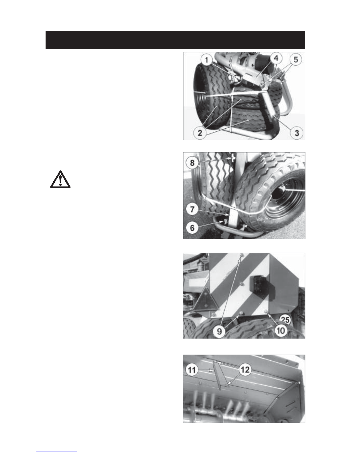
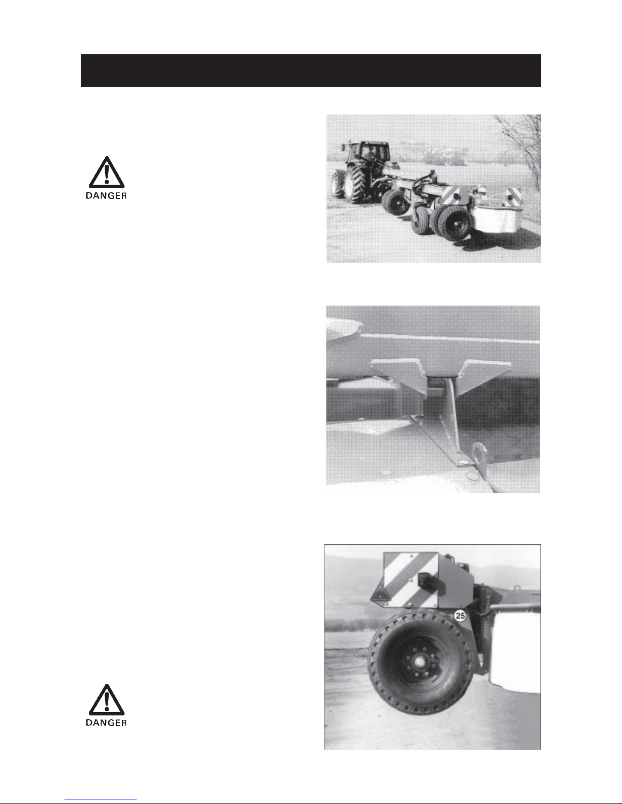
ASSEMBLY INSTRUCTIONS
The ALTERNA Mower Conditioner is shipped fully
assembled, except for the primary PTO shaft (1) and
the work wheels (2) which are unassembled to reduce
bulk. These loose components are attached to the
metallic drawbar support (3).
Drawbar support (3) has been specially designed for
improved ease of securing the unit in place and
facilitated handling and transporting for delivery.
1) Remove primary PTO shaft (1). Remove the
work wheels (2) and fit them on the work wheel
hubs.
Work wheels are to be fitted with the
valves on the outboard side of their
hubs.
Tighten wheel nuts to 15 daNm
(110 ft.lbs).
2) Remove drawbar support (3) as follows :
- Connect the two tractor draught arms to the
coupling yokes (4) by means of hitch pins (5).
- Lift the drawbar support (3) off the ground by
activating the tractor hydraulics.
- Remove pin (6) and lock parking stand (7) into
its vertical position using handle (8).
- Lower the tractor draught arms so that the
weight of the drawbar is supported by parking
stand (7).
- Remove the two pins (5) and take off the
drawbar support (3).
3) For reduced bulk, the left rear light support element has not been installed in its final position.
Remove bolts (9), untighten bolt (10) and straighten
up the light support until its mounting hole lines up
with the tapped hole of the chassis. Reinstall bolts
(9) and torque both bolts to 2 - 3 daNm (15 - 22
ft.lbs).
NOTE: The ALTERNA 400 are supplied with one
right deflector (11) and one left deflector to
be mounted inside the hoods using the original hardware (12) as shown on photo
opposite.
These deflectors enable forming even swaths
over the whole swath width when working in
slightly or moderately dense crops.
They must not be fitted for work in dense
or very dense crop.
Page 14
- 12 -
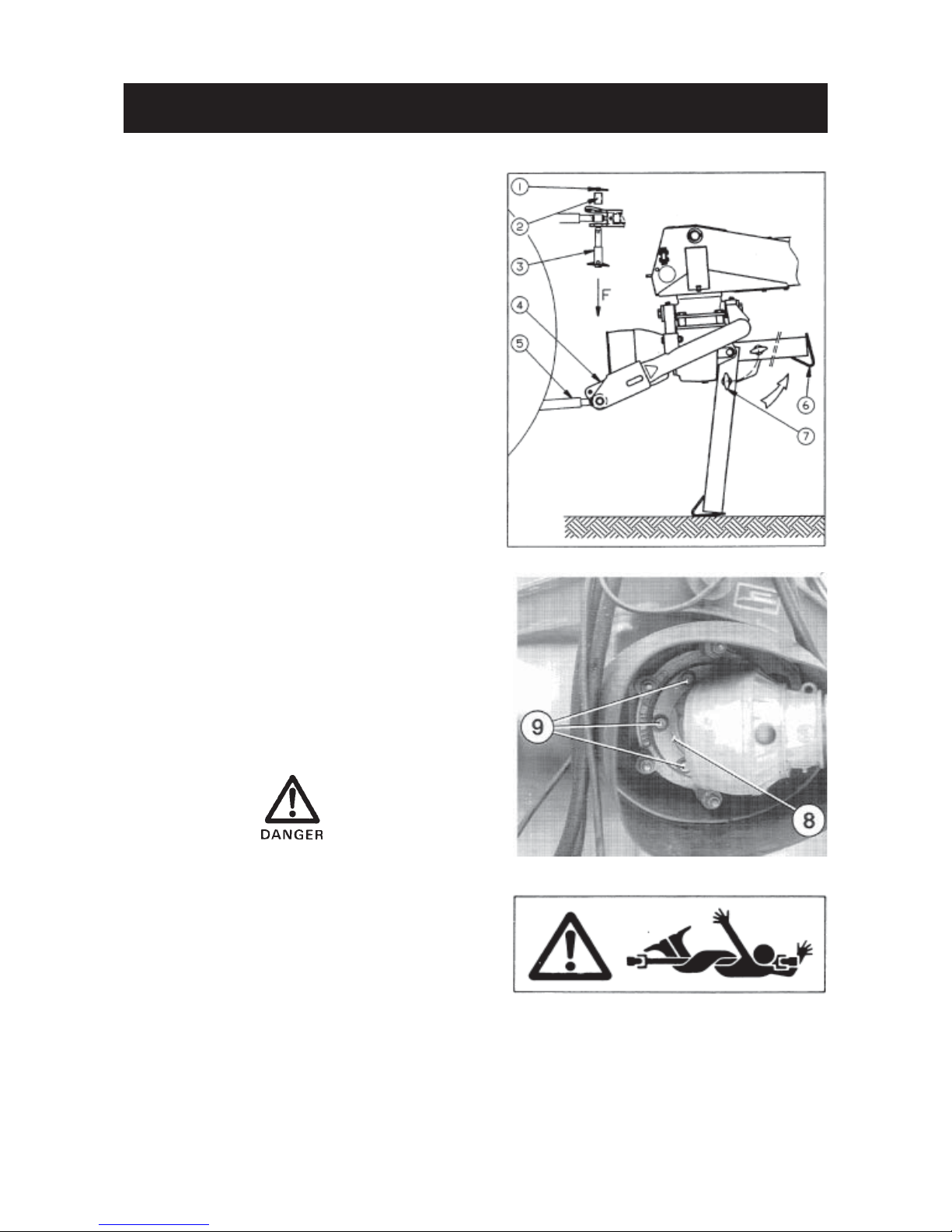
ATTACHMENT TO THE TRACTOR
- Back the tractor up to the mower conditioner and
attach lower links (5) to the interior of the pivoting
yokes (4) with hitch pins (3). Secure the hitch pins
with linchpins (1).
For category 2 tractors use 28 mm hitch pins (3). For
category 3 tractors use 37 mm hitch pins (3) and
spacers (2).
- Activate the tractor hydraulics to completely raise
lower links (5).
- Fold up parking stand (6) and lock in place using
handle (7).
- Secure the tractor lower links laterally using check
chains or linkage stabilizer bars provided at the same
time making sure that the tractor PTO and machine
input shaft are lined up in the vertical plane.
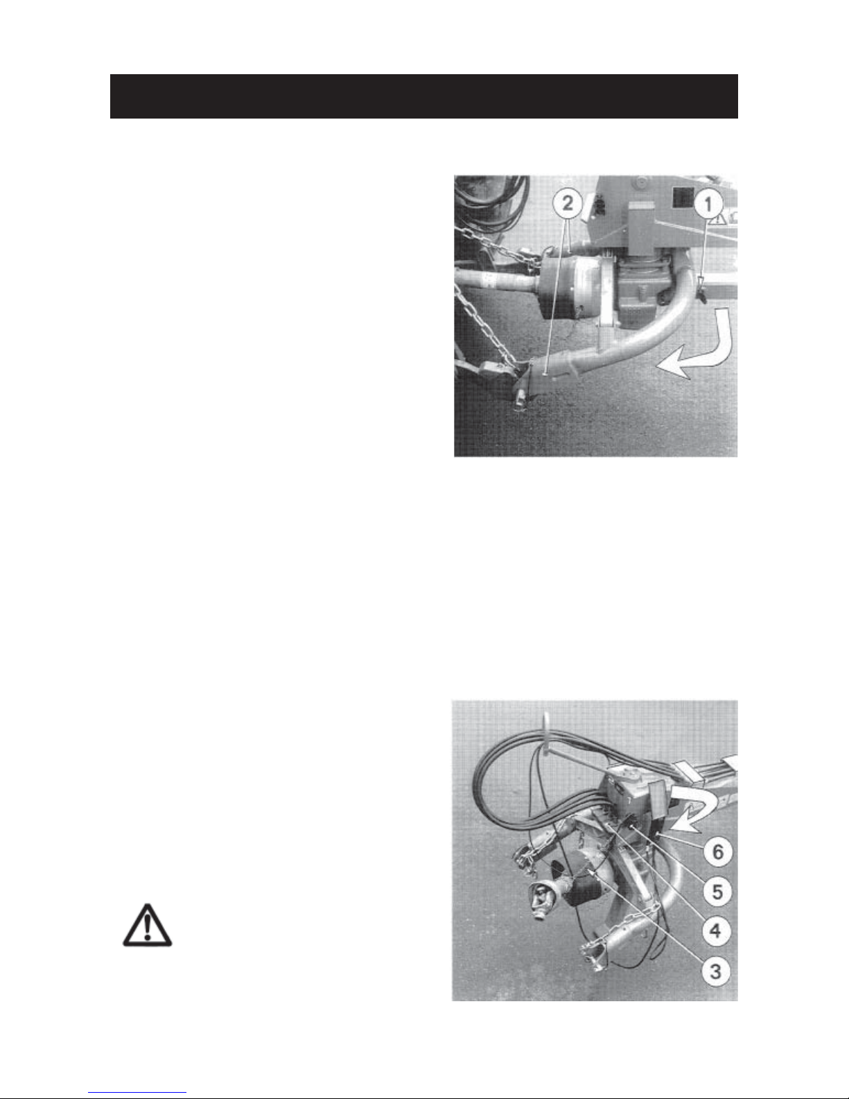
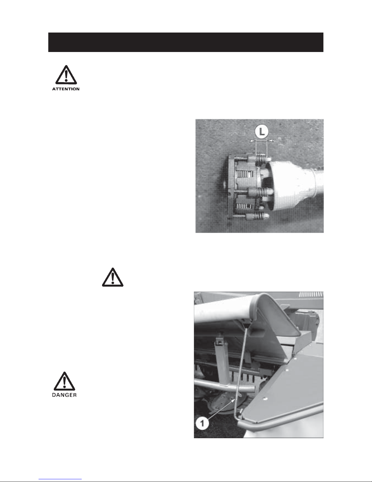
Fitting the primary PTO shaft :
Connect the primary PTO shaft’s flanged yoke (8) to the
Gyrodine slip clutch. Secure in place using 6 selflocking bolts (9) (M 12 x 25).
Tighten to a torque of 9 daNm (66 ft.lbs).
Make sure bolts are torqued to 9 daNm (66 ft.lbs).
To avoid accidents which could be serious, make
sure that the guards are always correctly in place
and secured with the safety chains. The safety
chain on the machine side must be attached on the
guard of the torque limiter. All worn or damaged
guards must be replaced immediately.
Page 15
- 13 -
ATTACHMENT TO THE TRACTOR
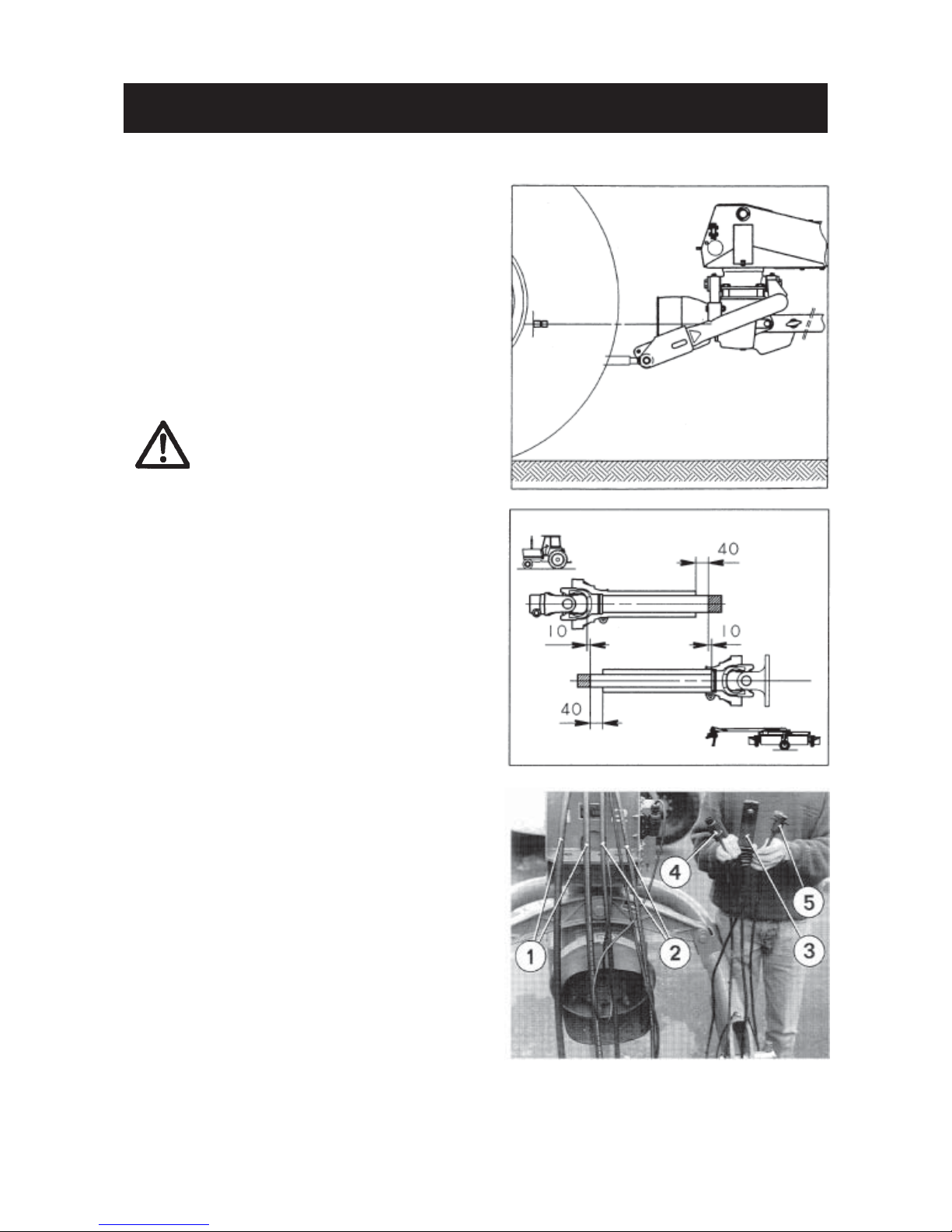
Make sure the PTO shaft length is correct for the
tractor being used.
1) Activate the tractor hydraulics to line up the
tractor PTO and the machine input shaft in the
horizontal plane.
2) Slide the other half PTO shaft (without torque
limiter) onto the tractor PTO and align both half
PTO shafts side by side. If there is excessive
overlap, mark and shorten the hatched portions
of the transmission tube keeping a safety clearance of 10 mm (0.5") between the ends of the
tubes and the yokes.
- Bevel and debur transmission
tubes. Remove all steel chips and
filings. Grease the inside of the
outer transmission tube.
- Shorten the guard tubes by the
same length as the transmission
tubes, as shown in the opposite
drawing.
- For your safety, there must be a
minimum tube overlap of 180 mm
(7") when the PTO shaft is in its
maximum extended position.
- Make sure the PTO shaft is connected to the 1000 min
-1
tractor
PTO.
3) All machine operations are controlled by the
tractor’s two double acting directional valves.
a) Connect hydraulic hoses (1) to the outlets of
the first directional valve, which will be referred to as DE1. Activating DE1 raises and
lowers the cutterbar.
b) Connect hydraulic hoses (2) to the outlets of
the second directional valve, which will be
referred to as DE2.
c) Carefully fit and cable the pre-cabled female
socket (5) (see electric lay-out, connections
and schematic).
d) Plug terminal (4) into the installed female
socket.
- Activating DE2 on its own sets the machine to
the right or to the left of the tractor.
- Activating DE2 and simultaneously pressing
thumb switch (3) raises and lowers transport
wheels.
Page 16
- 14 -
DETACHING THE MACHINE
Machine must be parked with the weight of the
tongue resting on the parking stand.
When parking the machine :
- Fully raise the tractor lower links.
- Pull out lock handle (1) which secures parking
stand in the horizontal position (the parking stand
lowers on its own).
- Move the lower end of the parking stand back and
forth so that it automatically locks into the vertical
parking position.
- Lower the tractor lower links until yokes (2) are
relieved of the drawbar’s weight.
- Block the wheels with wedges if the area is not even
and level.
- Uncouple the tractor draught arms, the check
chains and the PTO shaft.
Safety chain (3) supports the primary PTO shaft
when the machine is disconnected from the tractor.
In this position the PTO shaft is not in contact with the
ground, thus avoiding deterioration due to dust and
dirt. Holder (4) provides effective protection to the
hydraulic quick couplers.
Place electric terminal (5) in its support and house
the remote control handle (6) with its terminal in the
storage box provided and close the lid.
Park the machine on level ground
when it is in the transport position.
Page 17
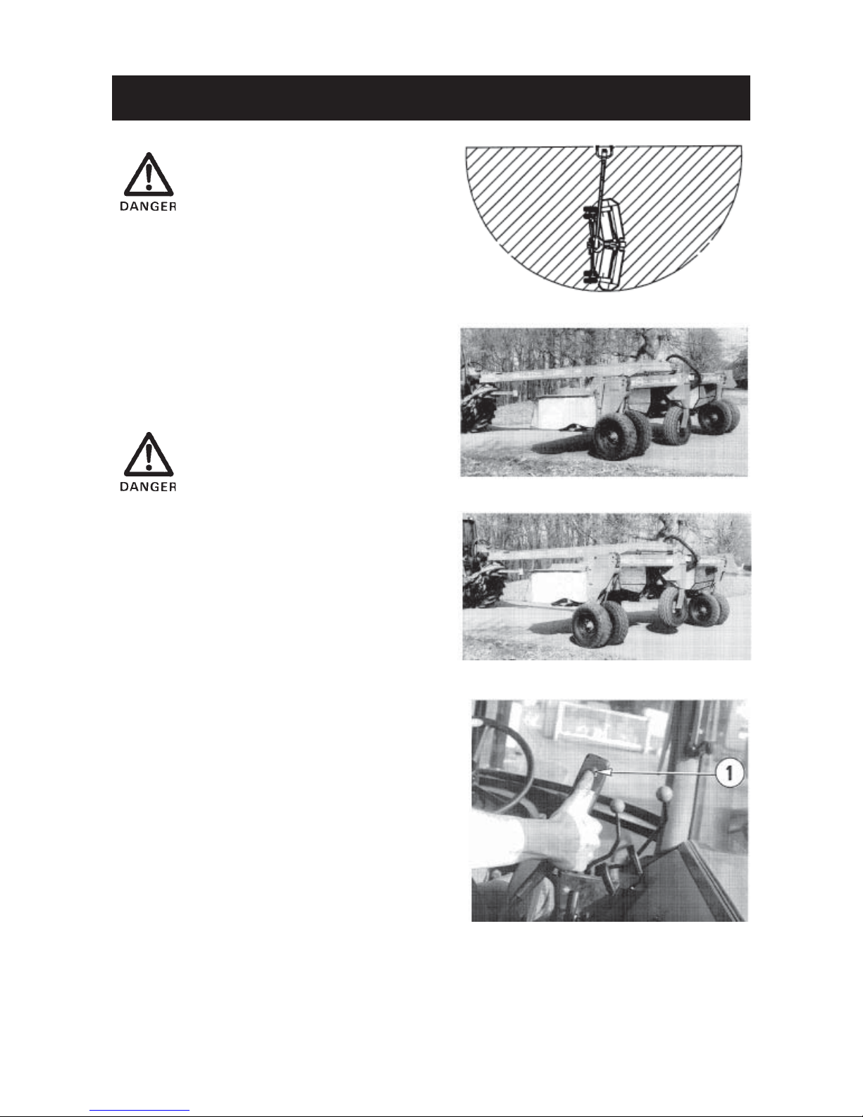
- 15 -
Always ensure that nobody is near
the machine pivoting zone
(hatched area on the drawing
opposite) before and while changing the machine from the road
transport position to the work po-
sition.
Changing the machine from the road
transport position to the work
position.
Before starting this switch over, double check that
the tractor lower links are completely raised.
When operating on sloping terrain and to avoid that the machine goes off course, activate
DE1 to extend the cylinders for
the work wheels so that they stay
as near to the ground as possible.
1) Activate DE2 until machine and drawbar are at a
90° angle to each other.
2) Activate DE1 to fully extend the cylinders for the
work wheels.
3) Press thumb switch and at the same time shift
DE2 in the same direction to raise the transport
wheels.
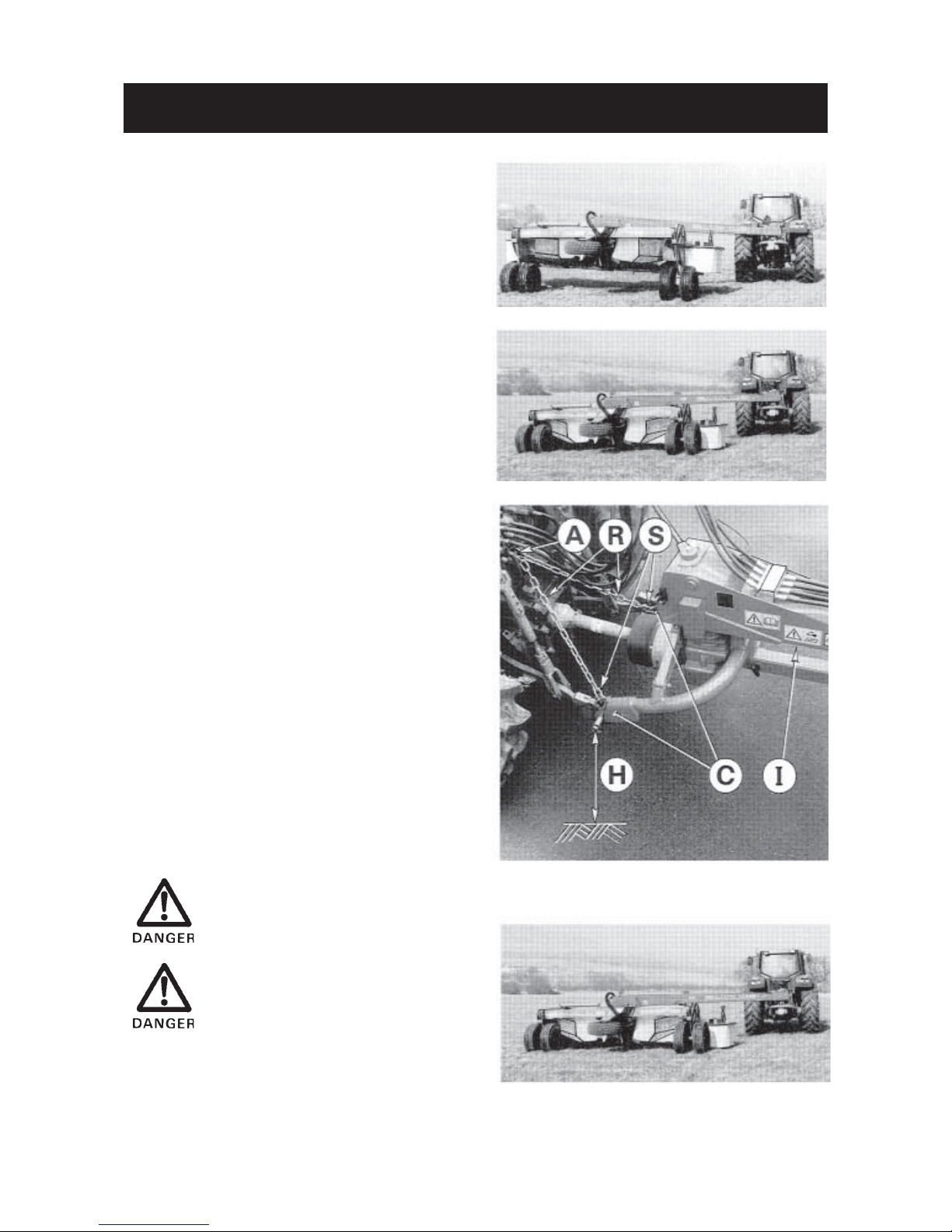
TRANSPORT TO WORK POSITION
Page 18
- 16 -
4 ) Operate DE2 to position machine to the left or the
right side of the tractor.
5) Move slowly forward until the work wheels are
aligned in the same direction as the tractor wheels.
6) Operate DE1 to fully retract the work wheel
cylinders and lower the cutterbar onto the ground.
7) With the tractor’s hydraulic 3-point lift, position
the Girodyne head in order to set the hitch pins at
a distance of 700 mm/ 2’4" from the ground.
Hook one end of the check chains (R) to the hitch
brackets (C) by means of the shackles (S) and
attach the other side to the tractor’s top link yoke
by means of the top link hitch pin (A).
Lower the 3-point lift. The attachment is correct
when the underside face (I) of the tongue is
approximately horizontal and the lower hitch pins
are at a distance (H) of around 650 mm/2’2"
from the ground when the check chains (R ) are
taut.
The cutterbar must rest on the
ground before engaging the PTO.
Never mow in stony or rocky
grounds.
TRANSPORT TO WORK POSITION
Page 19

- 17 -
Changing the machine from the work
position to the road transport position
It is advisable to first position machine to the right-hand
side of the tractor by shifting DE2.
1) Raise tractor lower links completely.
2) Activate DE1 to fully extend work wheel cylinders.
3) Press thumb switch and at the same time operate
DE2 to lower the transport wheels.
Note : Both transport wheel cylinders may not oper-
ate at the same speed. To assure that both
cylinders are fully extended, keep the valve
shifted for a few seconds after the front
transport wheel has closed up against its
stop. Then return DE2 to neutral.
4) Shift DE1 in the opposite direction to lower the
unit onto the transport wheels.
When operating on sloping terrain and to avoid that the machine goes off course, keep the
work wheels as near to the ground
as possible.
WORK TO TRANSPORT POSITION
While changing the machine from
the work position ot the road transport position:
- Stop tractor P.T.O. and wait for
rotating discs and rotor to stop.
- Always ensure that nobody is
near the machine pivoting zone
(hatched area on the drawing
opposite).
Page 20
- 18 -
WORK TO TRANSPORT POSITION
5 ) Shift DE2 in the same direction to align the chassis
with cutting/ conditioning unit under the drawbar.
If the machine does not pivot when
shifting DE2, then the transport wheel
position sensor has not been closed
by the rear transport wheel. Repeat
procedure described in points 2 and
3 to eliminate the fault.
6) Close the swathboards completely in order to
reduce the machine’s transport width.
Before transporting the machine ensure that :
a) The cutting/conditioning unit is correctly locked
under the drawbar.
b) Work wheels are fully raised (cylinder rods com-
pletely retracted).
c) The 4 hydraulic hoses are unplugged and the
quick couplers are housed in their support.
d) The electric terminal is unplugged so that the
tractor batteries are not run down.
Always check that the rear lights
and indicators are clean and functioning correctly before going on
the road.
Page 21
- 19 -
ADJUSTMENTS
Before carrying out any operation such as maintenance or adjustment on the
machine, stop the tractor engine, remove ignition key and wait for rotating discs and
rotor to stop before leaving the tractor.
1) Friction slip clutch
The friction slip clutch (code no. 557 901 00 for
ALTERNA 500 / 500 R and 522 835 00 for ALTERNA
400 / 400 R) is fitted to the rear of the primary PTO
shaft
Springs are factory set to a length of 35 mm for
ALTERNA 500 / 500 R and 33 mm for ALTERNA
400 / 400 R which enables torques up to 140 daNm
(1000 ft.lbs) for ALTERNA 500 / 500 R and 125
daNm (922,5 ft.lbs) for ALTERNA 400 / 400 R to be
transmitted. This setting is applicable to average
operating conditions.
Check if this setting is suitable for the given conditions during the first few hours of use :
- If the spring pressure is too light, plates slip
continuously or intermittently at frequent intervals,
resulting in overheating and rapid wear of the
friction plates.
- Over-pressured or completely coil bound springs
provide no protection to the drive components.
Never fully lock the springs.
2) Access to discs and knives for
service
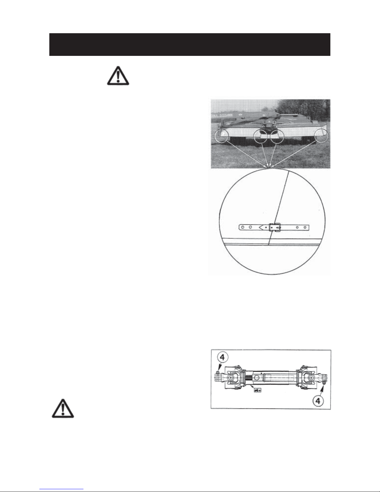
The front safety curtains can be maintained in the
raised position by means of lever (1) to gain access
to the cutterbar for service.
After having carried out service
work, fold down the guards and
connect curtains together using
the straps provided.
Page 22

- 20 -
ADJUSTMENTS
3) Cylinder stroke sensor for right-
hand cutting position
The rear cylinder (1) sets the position of the cutting/
conditioning unit relative to the drawbar :
- Fully retracted, cylinder (1) sets the unit to the left
side of the tractor for work.
- Fully extended, this cylinder places the unit in the
lengthway transport position.
- To mow at the tractor’s right, the cylinder (1) must
then be extended to an intermediary position which
is defined by the end position sensor (2) (P/N.
832 300 04). The sensor is activated by the core (3)
of the sliding rod (4) when the measure “A” = 557
mm / 1’10" is reached.
NOTE : The measure "A" = 557 mm / 1"10" is
preinstalled at factory.
4) Drawbar pressure pad adjustment
The preload applied by pushers (5) onto pressure
pad (6) is adjusted as follows :
- Rotate nuts (7) until all play has been taken up.
- Preload the conical spring washers (8) by retaining
the nuts (9) and tightening bolts (7) to a torque of
5 da N.m / 37 ft.lbs.
Page 23

- 21 -
ADJUSTMENTS
5) Cylinder stroke sensor for rear
transport wheel position
This sensor has been factory adjusted to open the
electric circuit when the rear transport wheel is
completely lowered. Readjustment may be necessary but only very occasionally.
- Fully extend work wheel cylinders, pivot the cut-
ting/conditioning unit at right angle to the drawbar
and completely raise the transport wheels.
- Undo lock nut (3) and screw in bolt (2) as far as it
will go.
- Press thumb switch and at the same time operate
DE2 to lower the transport wheels.
- Undo bolt (2) until its head operates the sensor (1)
which in turn extinguishes the blue indicator lamp
built into the junction box.
- Undo bolt (2) one more turn and retighten lock nut
(3), while at the same time keeping bolt (2) from
rotating.
- Ensure that a minimum safety clearence of 1 mm
is maintained between the bolt head and the sensor
plunger when it is fully drawn in.
For safety reasons the machine
cannot be pivoted into transport
position until the sensor (1) is activated by completely lowering
transport wheels.
Page 24

- 22 -
ADJUSTMENTS
6) Cutting height adjustment
Cutting height is adjusted by changing the position of the
central skid and replacing the 2 side skids.
When the machine leaves the factory it is equipped with 2
low side skids (1). To achieve a higher cut the 2 low side
skids (1) can be replaced by 2 middle skids or by 2 raised
skids delivered with the machine.
To replace the skids proceed as follows:
- remove the screws (2)
- loosen the self-locking nuts (3),
- remove the outer skids (1) installed at the factory and
install the middle skids or raised skids in the same place,
with the same screws and nuts (2 and 3) (torque to
8.5 daNm / 63ft.lbs).
To adjust the cutterbar central skid (4) proceed as follows :
- remove bolt (5) and pull out pin (6)
- Raise or lower the central skid (4) to set it at the same
height as the two side skids (1),
- secure the skid (4) in its new position by inserting pin (6)
through the corresponding hole. Secure in place with bolt
(5).
7) Cutterbar and conditioning unit
ground pressure
When the machine is in the working position (either on the
left or right side of the tractor, the underside of the
drawbar is horizontal), most of the cutterbar’s weight is
carried by a set of springs.
The ground pressure should be adjusted in
such a way that the left or right side of the
platform can be raised off the ground with a
force of 50 daN (which corresponds to a
weight of 50 kg/110 lbs).
Cutterbar down pressure is adjusted by
rotating bolt (6) after loosening lock nut (8).
- Rotating bolt (6) clockwise decreases down pressure.
- Rotating bolt (6) counter-clockwise increases down pres-
sure.
- Lock nut (7) prevents bolt (6) from moving upwards.
- Retighten lock nut (8) after each cutterbar ground pres-
sure adjustment.
Note : - For improved ease of adjustment, regularly lubri-
cate the threaded portion of bolt (6) and the
spherical area of its head.
- Check cutterbar and conditioning unit ground
pressure after the first hour of use.
Side skids Cutting height
Lo w 30 mm
Middle 40 mm
Raised 80 mm
Page 25

- 23 -
ADJUSTMENTS
8) Finger / comb conditioner
(ALTERNA 400 / 500)
The comb, located above the rotor, has 5 different
positions. Each position corresponds to the extent to
which the comb prongs intersect with the trajectory of
the free swinging fingers. To gain access to the levers
(1) lift the belt guards (2).
- Lowering levers (1) increases conditioning inten-
sity.
- Raising levers (1) decreases conditioning intensity.
Do not forget to close hoods (2) after
having manipulated handles (1).
Other than these five positions, which govern
conditioning intensity, the comb has the advantage of
being reversible and has two different conditioning
surfaces (one for natural grasses and one for more
delicate crops).
Disassembling and reversing comb :
- Remove bolts (3) connecting lever (1, 1a) and pin
(4) to the comb.
- Pull out pin (4).
- Remove the comb from the top.
- Reverse the comb, aligning it with the mounting hole
of pin (4).
- Insert pin (4) into the end of the comb and secure in
place using bolts (3).
Page 26
- 24 -
ADJUSTMENTS
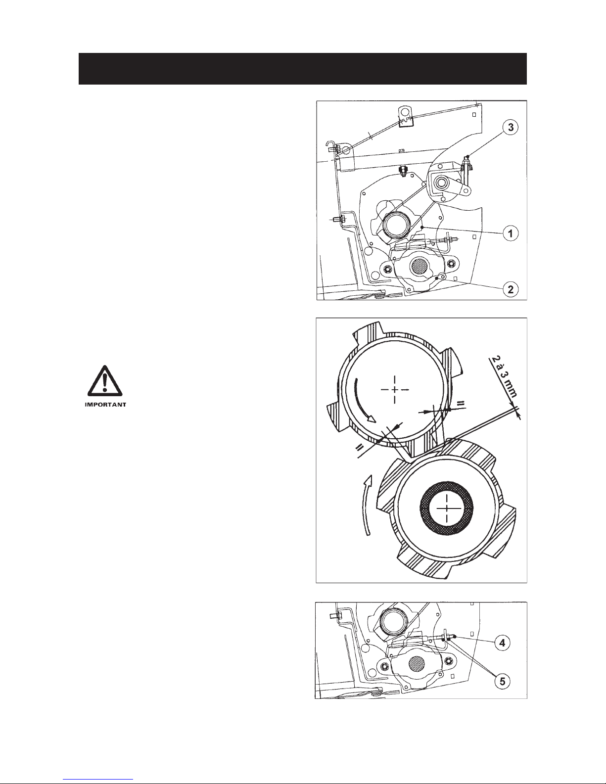
9) Roller conditioner
(ALTERNA 400 R / 500 R)
- Conditioning intensity is determined by the pres-
sure exerted on the crop by the upper roller (1) and
lower roller (2).
- This pressure can be adjusted between 0 to 5 daN/
cm (28 lbs/inch) by using self locking nut (3).
- Rotating nut (3) clockwise increases conditioning
intensity.
- Rotating nut (3) anti-clockwise decreases
conditioning intensity.
- From the factory, roller pressure is set at
approximately 2.5 kg/cm (14 lbs/inch).
- Clearance is set between 2 and 3 mm.
A minimum clearance of 2 mm
must always be maintained.
- Check the roll clearance and parallelism occasionally.
- Incorrect adjustment generates vibrations which
can create damage.
- Lateral stop screws (4) are used to adjust the
parallelism and clearance between the two
conditioning rollers.
- Do not forget to retighten counter-nuts (5) after
each adjustment.
Page 27
- 25 -
ADJUSTMENTS
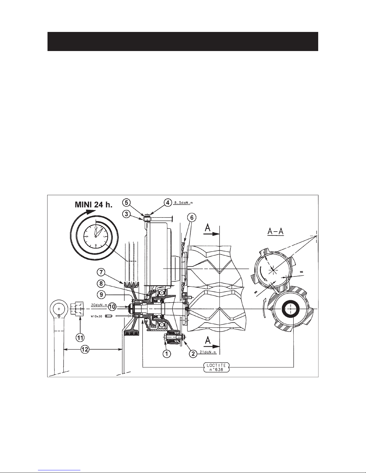
10) Timing the conditioning rollers after having removed the upper roller drive gearbox
If at any time it becomes necessary to remove the upper roller drive gearbox, then the following procedure
must be followed when reinstalling this gearbox to be sure the rollers are timed correctly and the gearbox
pulley has been installed correctly.
1. Slide the gearbox on the roller drive shafts.
2. Attach the gearbox using 2 screws (1) and 2 nuts (2).
3. Attach the link (3) on the gearbox with screw (4) and washer (5).
4. Lock the rollers using wooden wedges (6) by centring the upper roll in the lower roll, with equal distance between
the lugs and grooves of the opposite roll.
5. Thoroughly degrease the contact area between mounting surfaces of pulley (7)and pinion (8) using a grease
eliminator such as Loctite 7063.
6. Apply a Loctite 638 retaining product on these mounting surfaces.
7. Install pulley (7),washer (9), and nut (10) using socket (11) and pulley locking lever (12). Torque to 30 daNm/220
ft.lbs.
8. Do not put the machine into service before 24 hours after having installed the gearbox, to allow the bonding
adhesive to cure completely and develop good strength.
Page 28

- 26 -
ADJUSTMENTS
11) Belt tensioning
- The finger conditioning rotor and ribbed rollers are
driven by two sets of V-belts.
- It is critical that both sets of drive belts be checked
for correct tension after the first hour of operation.
- To do this, lift hood (2).
- Rotate nut (3) clockwise to tighten the belts.
- Belt tension is correct when each belt can be
deflected maximum 10 mm (1/2") when applying
pressure to the back of the belts at mid distance
between the pulleys.
Belts must not be changed individually. Only replace belts as a complete
set.
Loosen the belts when not using the
machine for long periods.
10 mm MAXI
12) Swath width :
Two adjustable swathboards enable the user to change
the swath width according to the crop density and the
weather conditions.
Loosen the screws (4) (ALTERNA 400/400 R) or the
handles (5) (ALTERNA 500/ 500 R), open or close
the flaps and retighten the screws (4) or the handles
(5). Torque screws (4) (ALTERNA 400/400 R) to a
high setting (such as 12 daNm / 88 ft.lbs) to keep
them tight.
- Wet soil, menacing sky : narrow swaths.
- Dry soil, clear sky : large swaths.
Page 29
- 27 -
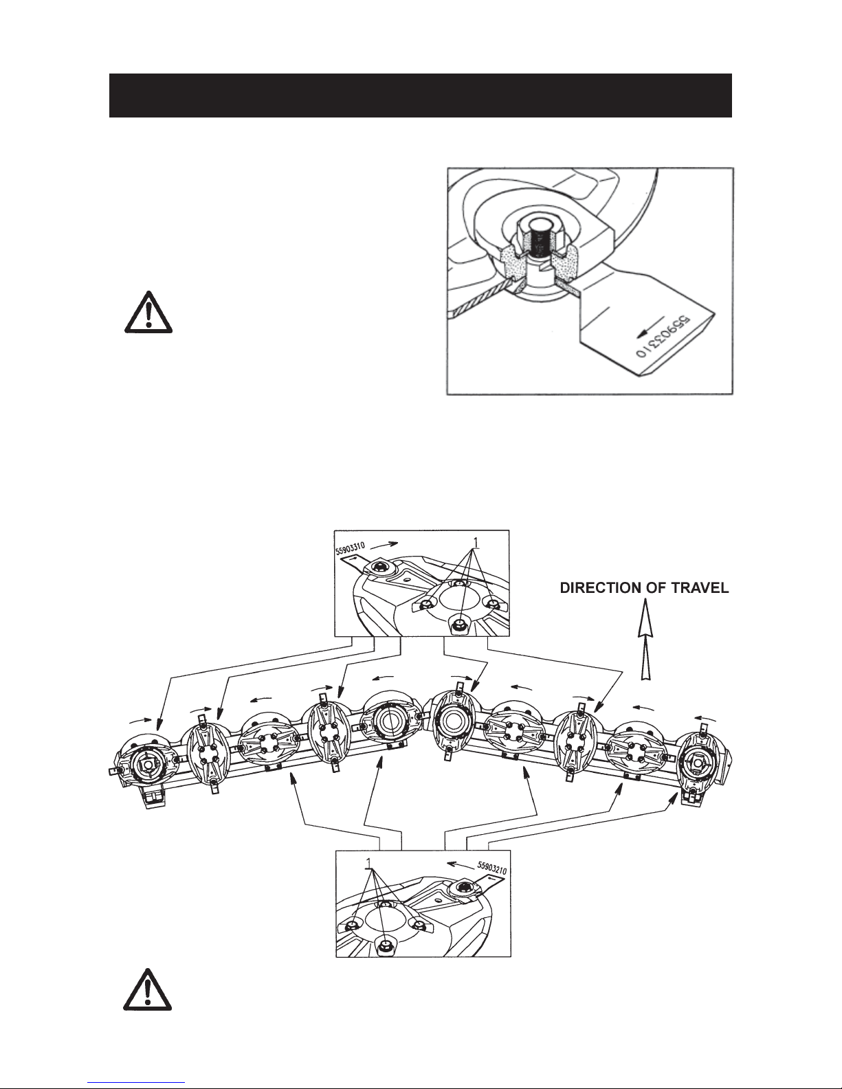
- Knives :
Knives are secured by bolt 561 158 00 and selflocking nut 802 012 62 (torque 12 daNm/90 ft.lbs)
Before re-using the nut and bolt, make sure they are
in good condition.
. Directional arrows are stamped in each
knife 559 032 10 (for counter-clockwise
rotating discs) and 559 033 10 (for
clockwise rotating discs) indicating
the direction of travel. Knives fitted to
an incorrect disc cause rugged cutting.
. Worn knives should either be turned
over to use the other cutting edge on
the same disc, or replaced.
. Knives, bolts and nuts are made of a
special steel. Never use replacement
parts other than genuine KUHN spare
parts.
- Discs :
a) To avoid interference between blades and discs,
scrupulously respect the disc positioning shown
in the figure below.
b) Discs are secured by 4 hexagon bolts (item 1)
(torque 13 daNm/95 ft.lbs)
SECURING DISCS AND KNIVES
ALWAYS REPLACE WORN OR DAMAGED ITEMS WITH GENUINE KUHN SPARE PARTS
Page 30
- 28 -
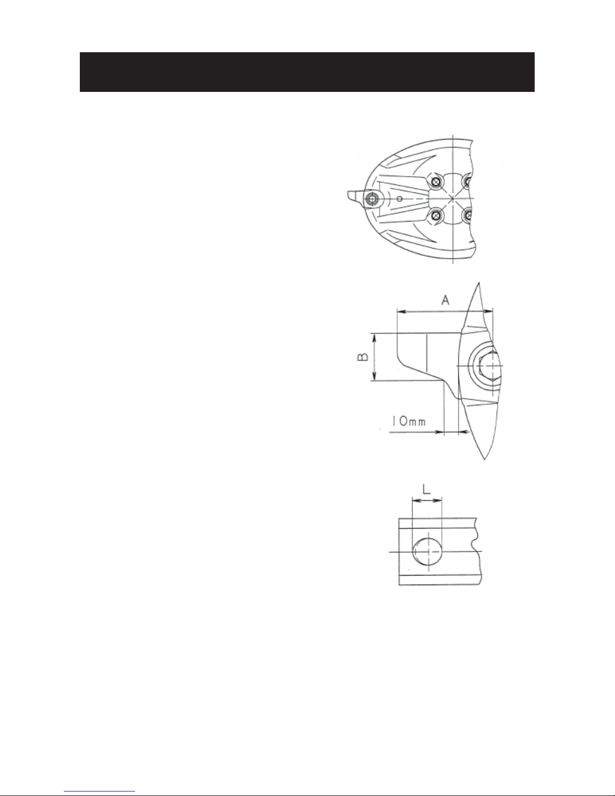
A. KNIVES : Should be inspected
systematically each time before the
machine is operated.
Cutting quality as well as safe operation depend on
the regular inspection and care given to the knives.
Knives should be replaced in the following cases :
1. Damaged knives
Very rough conditions can cause knives to crack
and become deformed leading to :
- increased risk of accidents ;
- deterioration of cutting quality ;
- risk of damage to the cutterbar.
2. Worn knives
Length (A) of a knife should be greater than 65 mm.
The width (B) of a knife, measured at a distance
of 10 mm away from the edge of the disc should
be greater than 34 mm
The hole (L) for the securing bolt must not become
oval by more than 20 mm for an 18 mm hole.
B. SECURING ELEMENTS :
To be inspected regularly !
(particularly the tightening torque of the nut:
12 daNm / 90 ft.lbs).
- Inspect immediately after hitting an obstruction.
- Inspect when replacing knives.
- Check at the beginning of each season.
INSPECTION OF KNIVES AND SECURING
ELEMENTS
Page 31
- 29 -
INSPECTION OF KNIVES AND SECURING
ELEMENTS
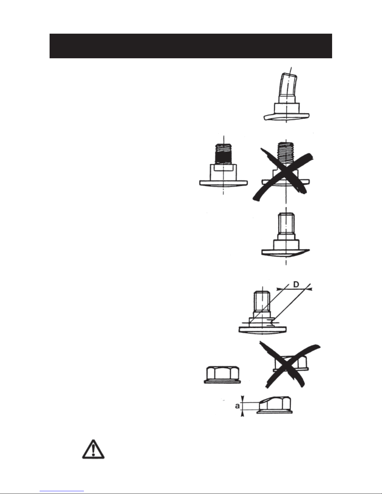
1. The securing bolt must be replaced:
- When a visible deformation is found.
- When the locking compound on the threads
has worn away or if the locking compound has
become inoperational due to inclusion of water,
oil or dirt.
- When wear on the head reaches the contact
area of the knife.
- When the diameter (D) of the bolt shoulder
is less than 15 mm (5/8 ").
2. The nuts must be replaced :
- When the contact washer has lost its elasticity
or when it becomes loose from the nut.
- When wear on the nut reaches a = 5 mm.
For the correct operation of your machine,
always use genuine KUHN spare parts.
Page 32
- 30 -
IMPORTANT RECOMMENDATIONS
1 ) Before starting work, lower the cutterbar onto the
ground and check that :
a) All safety guards have been lowered into work
position.
b) All safety curtains are fastened together with
the straps provided.
2) - The high pitched whine generated by the high
frequency of the discs will be considerably reduced when cutting.
- It is worthwhile to work with sharp knives.
- Adjusting the suspension system to lighten the
cutting/conditioning unit’s weight on the ground
allows the skids to glide over the ground without
damaging the grass stubble.
- It is important to retighten all bolts and nuts after
the first 2 - 3 hours of use.
3) Secondary PTO shaft
Retighten the conical bolts (4) of the
clamp yokes after the first day of use
(torque 15 daNm / 110 ft.lbs).
Page 33

- 31 -
LUBRICATION
IMPORTANT : Imperatively change oil in :
- cutterbars
- central gearbox
- Gyrodine gearbox
after the first 10 hours of use SAE 80 W EP (GL4).
Thereafter, oil must be changed after every 200 hours of work, or at least once per year.
I) Draining and refilling the 2 cutterbars
- Before draining oil, operate the cutterbar for at least 10 minutes so that oil warms up.
a) Before starting the machine make sure that :
- all guards, shields and curtains are in place
- everyone is kept away from the machine
b) Do not leave the tractor seat while the machine is running.
- Tilt the cutterbar. To do this, raise the platform, place a 300 mm (12") high wedge under one end skid and
a 150 (6") high wedge under the other end skid, then lower the platform onto the wedges.
- Remove end plate (1) from the lower end of the cutterbar and collect oil in a catchment tank of at least
3 1/2 pint capacity.
- Allow oil to drain completely. Wait for dripping to stop.
- Reinstall end plate (1) and the gasket. Tighten the three allen screws to 9.5 daNm (70 ft.lbs).
- To drain the second cutterbar, raise the platform, change over the wedges and proceed in the same
way.
- Refill each cutterbar with the correct quantity of SAE 80 W EP (GL4) oil as indicated below :
ALTERNA 400 : 1.4 litre / 3 US pints / 2.5 Imp. pints per cutterbar.
ALTERNA 500 : 1.7 litre / 3.5 US pints / 3 Imp. pints per cutterbar.
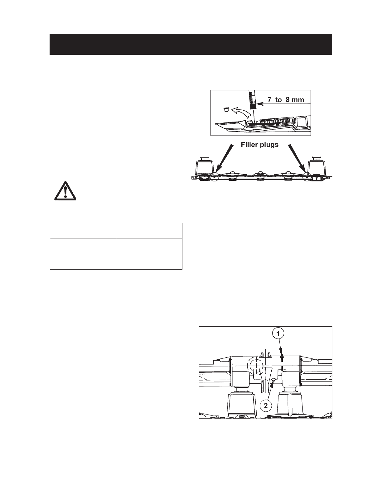
- Refill through the fill plugs (2) located at each cutterbar end.
Page 34
- 32 -
c) Refilling :
Cutterbar oil level can be checked by measuring oil
level through both filler plugs (2) when the cutterbar
is perfectly horizontal lengthways and resting on the
ground. Use a spirit level to ascertain that this is the
case. Correct oil level is 7 - 8 mm at both filler plugs.
Excessive oil will cause pressure build up and
overheating resulting in serious damage to the
cutterbar.
Practical Advice : Look on the machine’s parking
spot in order to detect any possible oil leak.
If in doubt as to the amount of oil
contained in the cutterbar, do not
add oil. Drain the oil completely and
refill with the prescribed quantity.
II) Central gearbox
- Check oil level and refill if necessary using dipstick
plug (1).
- Oil is drained by means of plug hole (2) in the
bottom of the gearcase.
- The gearbox is filled with 5.75 liters of SHELL
SPIRAX SAE 80 W EP (GL4) oil.
- Imperatively change oil after the first 10 hours of
use.
- Thereafter, oil must be changed after every 200
hours of work, or at least once per year.
- Periodically check oil level.
LUBRICATION
CHECKING OIL LEVEL
ALTERNA 500/500 R ALTERNA 400/400 R
Liter 2 x 1,7 Liter 2 x 1,4
US pints 2 x 3.5 US pints 2 x 3
Imp. pints 2 x 3 Imp. pints 2 x 2.5
Page 35

- 33 -
LUBRICATION
III) Gyrodine Gearbox
The gearbox is filled with 6 liters of SHELL SPIRAX
SAE 80 W EP (GL4) oil. Check oil level and refill if
necessary using plug (1) which has a dipstick (3) with
an inlaid mark (4) indicating oil level.
Oil can be drained by means of plug hole (2).
- Imperatively change oil in after the
first 10 hours of use.
- Thereafter, oil must be changed after
every 200 hours of work, or at least
once per year.
- Periodically check oil level.
IV) Upper central pivot gearbox
The upper central pivot gearbox (5) is fitted with 1.75
liters of SHELL SPIRAX EP 80 oil. Check oil level and
refill if necessary using plug (7) which has a dipstick
(6) with an inlaid mark indicating oil level. Drain oil by
drawing it up through hole (7) using a syringe.
Note : The upper central pivot gearbox has been
equipped with this dipstick as from the 1999
production year.
V) Lower central pivot gearbox
Lower central pivot gearbox (8) is filled with 1.75
liters of SHELL SPIRAX SAE 80 W EP (GL4) oil.
Check oil level and refill if necessary using plug hole
(9). Oil level is correct when the oil reaches the edge
of hole (9).
Oil can be drained by means of plug hole (10).
Page 36

- 34 -
LUBRICATION
It is forbidden to discard oil, grease or filters of any type. These must be given to
specialised waste disposal organisations to protect the environment.
VI) Grease Fittings
There are 20 grease fitting on the ALTERNA mower
conditioner as shown on the following photos. Some
guards have been removed for clearer illustration.
Grease all points every 8 hours of work, with Shell
Multi-Purpose grease NLGI grade 2.
All grease fittings are identified by the decal
opposite.
For safety reasons grease points (4 and 5) with work wheel cylinders retracted.
Page 37

- 35 -
LUBRICATION
Page 38

- 36 -
LUBRICATION
VII) Primary PTO shaft
Grease with Shell Multi-Purpose grease NLGI grade 2
the primary PTO shaft at the hourly intervals shown on
the diagram. Clean fittings before applying grease.
VIII) Secondary PTO shaft
Grease the secondary PTO shaft at the hourly intervals
shown on the diagram with Shell Multi-Purpose
grease NLGI grade 2. Clean fittings before applying
grease.
Note : The telescopic tubes are greased through
hole (17) provided in the guard tubes
without removing the PTO shaft.
OPTIONAL EQUIPMENT
1. PTO SHAFT YOKES :
- 1 3/8 6 splines - Kit no. 4503 710
- 1 3/4 6 splines - Kit no. 4503 712
- 1 3/4 20 splines - Kit no. 4503 713
2. Rigidified blades
Ref. 564 516 00 x 16 (ALTERNA 400)
Ref. 564 516 00 x 20 (ALTERNA 500)
Rigidified blades may be recommended for mowing in difficult conditions.
3. Wide spreading equipment for ALTERNA 500/500 R - Kit no. 108 6920.
This equipment enables spreading the crop in an even layer over the whole mowing-conditioning unit
width.
See separate Bulletin No. 058 605 10 supplied with this equipment.
Page 39

- 37 -
STORAGE
I - AT THE END OF THE SEASON
1. Thoroughly clean the mower conditioner.
2. Check the condition of the machine. List the replacement parts that will be needed. Order replacement parts
early from your Kuhn dealer so that they may be fitted during the slack period.
3. Repaint the rusted parts of the machine and all areas were the paint has worn off.
4. Drain oil from all gearcases and cutterbars and refill with the precribed quantity of the correct grade oil. Apply
grease to all fittings as described in the lubrication section.
5. Store the machine in a dry place.
6. Park the machine in transport position. Oil the rods of all cylinders that are not retracted (ie. 1 central pivot
cylinder; 2 transport wheel cylinders).
7. Slacken the V-belts and check their condition.
II - AT THE BEGINNING OF THE SEASON
1. Attach the machine to the tractor and place it on level ground in the working position.
2. Check all oil levels and grease the machine as described in the lubrication section.
3. Retension the V-belts (see adjustments section). Make sure all guards are firmly secured in place and in good
working order.
4. Decompress the torque limiter’s springs and allow the clutch to slip. Then readjust the torque limiter as
described in the corresponding section.
5. Check tire inflation for the correct pressure of 2.7 bar / 40 psi.
6. Inspect all knives and the hardware used to hold them in place (see the corresponding section).
7. Check that all nuts and bolts are sufficiently tightened.
8. READ THIS OPERATORS MANUAL ONE MORE TIME.
Page 40

- 38 -
REMEDY
Bring PTO speed (rotational
frequency) up to 1000 rpm (min-1)
and set it with the hand throttle
Check that the arrow marked
on the knife corresponds with the
disc’s direction of rotation
Replace knives
Reduce forward speed
Adjust down pressure of
cutting/conditioning unit
Review skid adjustment
Reduce cutting/conditioning unit
down pressure
Correct position of conditioning
combs or reverse them if necessary
Adjust rollers so that they are
parallel by means of the side stops
Bring PTO speed (rotational
frequency) up to 1000 rpm (min-1)
and set it with the hand throttle
Retension or replace belts
Check that the tensioning pulley
is correctly aligned in respect to
the drive and driven pulleys
.../...
POSSIBLE CAUSE
Insufficient PTO speed
(rotational frequency)
Knives fitted incorrectly
Damaged or broken knives
Excessive forward speed
Flotation of cutterbar/
conditioning unit poorly adjusted
Skids incorrectly adjusted
Working in very wet conditions
Excessive ground pressure
Conditioning combs
incorrectly positioned
Conditioning rollers are
no longer parallel
Insufficient PTO speed
(rotational frequency)
PROBLEM
Poor cutting quality
Stubble too high
Soil accumulates in front
of the cutterbar
Damaged leaves and
crushed stems
Rotor clogging
TROUBLE SHOOTING GUIDE
Most operating problems that can occur with the
machine are due to incorrect adjustments or poor
maintenance. The following chart has been designed to help you solve problems by suggesting a
probable cause and the recommended solution.
These suggested remedies should be applied with
caution. Make sure that the source of the problem is
not located in an area different from the one where it
is listed. A thorough understanding of the machine is
required to correct operating problems.
Page 41

- 39 -
TROUBLE SHOOTING GUIDE
PROBLEM
Excessive vibration
Poor adaptation to uneven
terrain
Poorly shaped swaths
Hydraulic system operates
slowly
REMEDY
Replace any damaged or missing
rotor fingers (replace in pairs of
equal weight)
Adjust conditioning rollers to be
parallel by means of the side stops
Replace conditioning roller(s)
Increase ground pressure
and/or
reduce forward speed
Adjust tractor lower links to a height
of 650 mm (2' 2")
If necessary, fit stop chains
Retension or replace belts
Bring PTO speed (rotational
frequency) up to 1000 rpm (min-1)
and set it with the hand throttle
Adapt tractor speed to condition
of crop and density
Adapt comb adjustment to condition
of crop
Correct the swathboard position
Clean and/or replace elements (see
hydraulic schematic)
POSSIBLE CAUSE
Unbalanced conditioning rotors
Conditioning rollers are
no longer correctly adjusted
to be parallel
Damaged conditioning roller(s)
Insufficient ground pressure
and/or
excessive forward speed
Poorly adjusted tractor lift arms
Erratic rotor or roller drive
Incorrect PTO speed
(rotational frequency)
Excessive forward speed
Incorrect comb adjustment
Swathboards incorrectly adjusted
Restriction in filters
Page 42

- 40 -
HYDRAULIC SCHEMA TIC
The hose connector body
at the front of the drawbar
houses 4 metal filter
screens which should be
removed and cleaned twice
per season for trouble free
function of the hydraulics.
Use a 38 mm wrench to
remove the 4 ports which
maintain the filter screens
in place.
Page 43
- 41 -
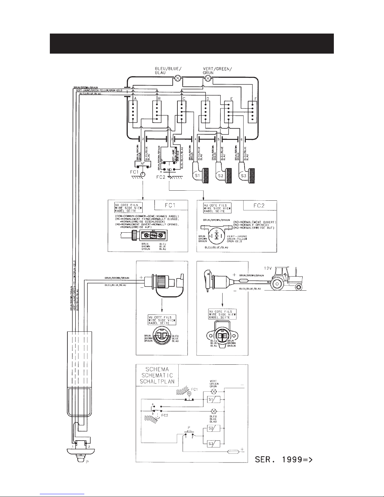
ELECTRIC LAY OUT, CONNECTIONS AND SCHEMATIC
Page 44

- 42 -
ELECTRICAL CONNECTOR (for North America)
KUHN wiring harnesses are supplied with an ISO (International Standards Organization) 1724 plug connector.If
the implement is to be operated with a tractor equipped with an SAE style seven-pin connector a SA J 560b plug
must be installed. If required, the SAE J 560b plug is factory supplied with the machine.
Implement wiring harness description
Colors Function Terminal connection
ISO 1724 plug SAE J 560b plug
White Ground 3 1
Black Left running lights 7 6 *
Yellow Left turn & hazard 1 3
Red Stop lights 6 4 **
Green Right turn & hazard 4 5
Brown Right running lights 5 6 *
Blue Not used 2 7
* Note that the black and brown wires must be connected together on SAE type connectors for proper light
opération.
** The red wire should only be attached to the #4 terminal if the #4 terminal on the tractor is confirmed to be
a brake light terminal. If the tractor has no brake terminal the red wire of the implement should be sealed
off and not connected to any terminal.
Page 45

- 43 -
SOUND LEVELS
Sound levels given out by : Mower Conditioner ALTERNA 400 / 400 R - 500 / 500 R
Sound levels have been measured in accordance with the measuring methods as defined in :
HM Agricultural Inspectorate
AGRICULTURAL MACHINERY NOISE
Legislation and guidance on methods of testing
(Annex to AIC 1896/117 REV)
February 1988
Health and Safety Executive
The method employed corresponds to the method No. 4 in this document. Unspecified testing
conditions comply with ISO 5131 standard.
Measuring equipment conforms to NF S 31-009 standard. The tractor used has a power of 170 kW.
A-weighted emission sound pressure level L (A) eq inside tractor cab (with closed windows) :
Tractor only = 76.7 dB (A)
Tractor + machine = 77.8 dB (A)
Page 46

LIMITED WARRANTY
KUHN S.A. of 4 Impasse des Fabriques, 67706 SAVERNE CEDEX, France (hereinafter called the
«Company») warrants, in accordance with the provisions below, to each original retail purchaser of
KUHN new equipment of its own manufacture, from an authorized KUHN dealer, that such equipment
is, at the time of delivery to such purchaser, free from defects in material and workmanship and that
such equipment will be warranted for a period of one year starting from the date the goods are delivered
to the end user and during this period up to a limit of 500 hours use, providing the machine is used and
serviced in accordance with the recommendations in the Operator’s Manual.
THESE CONDITIONS ARE SUBJECT TO THE FOLLOWING EXCEPTIONS :
1. Parts of machines which are not of our manufacture i.e. tyres, belts, P.T.O. shafts, clutches etc., are not
covered by this Limited Warranty but are subject to the warranty of the original manufacturer. Any claim
falling into this category will be taken up with the manufacturer concerned.
2. Warranty claims applying to these types of parts must be handled in the same way as if they were parts
manufactured by KUHN. However, compensation will be paid in accordance with the warranty agreement of the manufacturer concerned in as much as the latter justifies such a claim.
3. This Limited Warranty will be withdrawn if any equipment has been used for purposes other than for
which it was intended or if it has been misused, neglected or damaged by accident or let out on hire. Nor
can claims be accepted if parts other than those manufactured by us have been incorporated in any of
our equipment. Furthermore, the Company shall not be responsible for damage in transit or handling by
any common carrier and under no circumstances within or without the warranty period will the Company
be liable for damages for loss of use or damages resulting from delay or any consequential damage.
We cannot be held responsible for loss of earnings caused by a breakdown or for injuries either to the owner
or to a third party, nor can we be called upon to be responsible for labor charges, other than originally
agreed, incurred in the removal or replacements of components.
THE CUSTOMER WILL BE RESPONSIBLE FOR AND BEAR THE COSTS OF:
1. Normal maintenance such as greasing, maintenance of oil levels, minor adjustments, etc.
2. Transportation of any kind of any KUHN product to and from the place the warranty work is performed.
3. Dealer travel time to and from the machine or to deliver and return the machine from the workshop for
repair.
4. Dealer travelling costs.
Parts defined as normal wearing items are listed as follows and are not in any way covered under this
Limited Warranty :
V belts, discs, knives, wear plates, disc guards, tires, torque limiters, hydraulic hoses, pitman shafts, swath
sticks, blades, tines and tine holders.
KUHN Limited Warranty will not apply to any product which is altered or modified without the expressed
permission of the Company and/or repaired by anyone other than Authorized Service Distributors or
Authorized Service Dealers.
Page 47

LIMITED WARRANTY IS DEPENDENT UPON THE STRICT OBSERVANCE BY THE
PURCHASER OF THE FOLLOWING PROVISIONS :
- That this Limited Warranty shall not be assigned or transferred to anyone unless the Company’s consent in
writing has first been obtained.
- The warranty/product registration form has been correctly completed by dealer and purchaser with their
names and addresses, dated, signed and returned to the appropriate address as given on the warranty/
product registration form.
- The claim form sent to KUHN has been correctly completed stating:
* dealer’s name and address
* owner’s name and address
* type of machine
* machine serial number
* delivery date to buyer
* date of failure
* tractor make and type
* description of the failure and its cause
* quantity , reference number and name of the damaged p arts
* reference number, quantity and date of the invoice for the replacement p arts.
- The judgement of the Company in all cases of claims under this Limited Warranty shall be final and conclu-
sive and the purchaser agrees to accept its decisions on all questions as to defect and to the exchange of
any part or parts.
- That all safety instructions in the Operator’s Manual shall be followed and all safety guards regularly inspected
and replaced where necessary .
No warranty is given on second-hand products and none is to be implied. Persons dealing in the Company’s
products are in no way legal agents of the Company and have no right or authority to assume any obligation
on their behalf, express implied, or to bind them in any way .
KUHN S.A. reserves the right to incorporate any change in design in its products without obligation to make
such changes on units previously manufactured.
Moreover, because of the constant progress in technology, no guarantee is given to the descriptions of
equipment published in any document by the company .
DISCLAIMER OF FURTHER W ARRANTY
There are no warranties, expressed or implied, except as set forth above. There is no
warranty of merchantability. There are no warranties which extend beyond the description
of the product contained herein. In no event shall the company be liable for indirect, special
or consequential damages (such as loss of anticipated profits) in connection with the retail
purchaser’s use of the product.
Page 48

- N O T E S -
Page 49

Page 50

Page 51

This machine complies with the safety requirements of the European machinery directive.
The Operator should respect all Health and Safety regulations as well as the Highway
Code. For your own safety, use only genuine KUHN spare parts. The manufacturer
disclaims all responsibilities due to incorrect use or non-compliance with the
recommendations given in this manual.
Page 52

Printed in France by KUHN
KUHN S.A. 4 Impasse des Fabriques F - 67706 SAVERNE CEDEX (FRANCE)
Tél. : + 33 (0) 3 88 01 81 00 - Fax : + 33 (0) 3 88 01 81 03
www.kuhnsa.com - E-mail : info@kuhnsa.com
Société Anonyme au Capital de 19 488 000 Euros
For your safety
and to get the best from your machine,
use only genuine KUHN parts
 Loading...