


Original instructions
RN019AGB A
OPERATOR’S MANUAL
Fertilizer spreader
AXIS H EMC
RN019AGB A
- English - 02-2011

Preface
Dear customer,
you have shown your trust in our product by the purchase of a Series AXIS H + EMC solid fertilizer
broadcaster. Thank you! We want to justify your trust. You have purchased a powerful and reliable
solid fertiliser broadcaster.
However, if any problems occur: Our Customer Service is always ready to help.
Please read this operator's manual carefully before using the solid fertiliser broadcaster
and observe the instructions.
The operating instructions offer a comprehensive operational overview and give you valuable information regarding assembly, maintenance and care of the product.
The manual could also describe equipment that is not included in your mineral fertiliser spreader.
You should be aware that damage caused by incorrect operation or improper use cannot be covered by warranty claims.
n CAUTION
Please enter your model type and serial number together with the year of
manufacture of your solid fertiliser broadcaster here.
You can find this information either on the manufacturer's nameplate or on the
frame of the product.
Please state this information whenever you wish to order spare parts, accessories or in case of complaints.
Technical improvements
Model: Serial number: Year of manufacture:
We are continuously improving our products. For this reason, we reserve the right to make any
improvements and necessary changes to our product line without prior notice. However, we are
not obligated to apply such improvements or changes to machines that have already been sold.
We will be pleased to answer any other questions that you might have.
Yours sincerely
Kuhn S.A.
Farm Machinery


Table of Contents
Preface
1 Intended use 1
2 User instructions 3
2.1 About this operator's manual . . . . . . . . . . . . . . . . . . . . . . . . . . . . . . . . . . . . . . . . . . . 3
2.2 Structure of the operator's manual . . . . . . . . . . . . . . . . . . . . . . . . . . . . . . . . . . . . . . 3
2.3 Depictions in the text . . . . . . . . . . . . . . . . . . . . . . . . . . . . . . . . . . . . . . . . . . . . . . . . . 4
2.3.1 Directions and instructions. . . . . . . . . . . . . . . . . . . . . . . . . . . . . . . . . . . . . . . 4
2.3.2 Lists . . . . . . . . . . . . . . . . . . . . . . . . . . . . . . . . . . . . . . . . . . . . . . . . . . . . . . . . 4
2.3.3 References. . . . . . . . . . . . . . . . . . . . . . . . . . . . . . . . . . . . . . . . . . . . . . . . . . . 4
3 Safety 5
3.1 General Information. . . . . . . . . . . . . . . . . . . . . . . . . . . . . . . . . . . . . . . . . . . . . . . . . . 5
3.2 Significance of warnings . . . . . . . . . . . . . . . . . . . . . . . . . . . . . . . . . . . . . . . . . . . . . . 5
3.3 General safety information. . . . . . . . . . . . . . . . . . . . . . . . . . . . . . . . . . . . . . . . . . . . . 7
3.4 Operator instructions . . . . . . . . . . . . . . . . . . . . . . . . . . . . . . . . . . . . . . . . . . . . . . . . . 7
3.4.1 Personnel qualification. . . . . . . . . . . . . . . . . . . . . . . . . . . . . . . . . . . . . . . . . . 7
3.4.2 Orientation . . . . . . . . . . . . . . . . . . . . . . . . . . . . . . . . . . . . . . . . . . . . . . . . . . . 7
3.4.3 Accident prevention . . . . . . . . . . . . . . . . . . . . . . . . . . . . . . . . . . . . . . . . . . . . 8
3.5 Operating safety instructions . . . . . . . . . . . . . . . . . . . . . . . . . . . . . . . . . . . . . . . . . . . 8
3.5.1 Parking the solid fertiliser broadcaster. . . . . . . . . . . . . . . . . . . . . . . . . . . . . . 8
3.5.2 Filling the solid fertiliser broadcaster . . . . . . . . . . . . . . . . . . . . . . . . . . . . . . . 8
3.5.3 Inspection before startup . . . . . . . . . . . . . . . . . . . . . . . . . . . . . . . . . . . . . . . . 9
3.5.4 During operation. . . . . . . . . . . . . . . . . . . . . . . . . . . . . . . . . . . . . . . . . . . . . . . 9
3.6 Fertiliser . . . . . . . . . . . . . . . . . . . . . . . . . . . . . . . . . . . . . . . . . . . . . . . . . . . . . . . . . . 9
3.7 Hydraulics . . . . . . . . . . . . . . . . . . . . . . . . . . . . . . . . . . . . . . . . . . . . . . . . . . . . . . . . 10
3.8 Service and maintenance . . . . . . . . . . . . . . . . . . . . . . . . . . . . . . . . . . . . . . . . . . . . 11
3.8.1 Maintenance personnel qualification . . . . . . . . . . . . . . . . . . . . . . . . . . . . . . 11
3.8.2 Parts subject to wear and tear . . . . . . . . . . . . . . . . . . . . . . . . . . . . . . . . . . . 11
3.8.3 Service and repair tasks. . . . . . . . . . . . . . . . . . . . . . . . . . . . . . . . . . . . . . . . 11
3.9 Traffic safety . . . . . . . . . . . . . . . . . . . . . . . . . . . . . . . . . . . . . . . . . . . . . . . . . . . . . . 12
3.9.1 Checks before driving . . . . . . . . . . . . . . . . . . . . . . . . . . . . . . . . . . . . . . . . . 12
3.9.2 Road travel with the solid fertiliser broadcaster . . . . . . . . . . . . . . . . . . . . . . 13
3.10 Protective equipment built into the machine . . . . . . . . . . . . . . . . . . . . . . . . . . . . . . 14
3.10.1 Positioning of the protective equipment . . . . . . . . . . . . . . . . . . . . . . . . . . . . 14
3.10.2 Protective device functions . . . . . . . . . . . . . . . . . . . . . . . . . . . . . . . . . . . . . 16
3.11 Warning and instruction message stickers . . . . . . . . . . . . . . . . . . . . . . . . . . . . . . . 17
3.11.1 Warning stickers. . . . . . . . . . . . . . . . . . . . . . . . . . . . . . . . . . . . . . . . . . . . . . 18
3.11.2 Instruction stickers and factory plate . . . . . . . . . . . . . . . . . . . . . . . . . . . . . . 19
3.12 Reflectors. . . . . . . . . . . . . . . . . . . . . . . . . . . . . . . . . . . . . . . . . . . . . . . . . . . . . . . . . 20
I

Table of Contents
4 Technical data 21
4.1 Machine information . . . . . . . . . . . . . . . . . . . . . . . . . . . . . . . . . . . . . . . . . . . . . . . . . 21
4.1.1 Manufacturer. . . . . . . . . . . . . . . . . . . . . . . . . . . . . . . . . . . . . . . . . . . . . . . . . 21
4.1.2 Versions . . . . . . . . . . . . . . . . . . . . . . . . . . . . . . . . . . . . . . . . . . . . . . . . . . . . 21
4.1.3 Specifications of base equipment. . . . . . . . . . . . . . . . . . . . . . . . . . . . . . . . . 22
4.1.4 Specifications of attachments and attachment combinations. . . . . . . . . . . . 23
4.2 List of available optional equipment . . . . . . . . . . . . . . . . . . . . . . . . . . . . . . . . . . . . . 24
4.2.1 Extensions . . . . . . . . . . . . . . . . . . . . . . . . . . . . . . . . . . . . . . . . . . . . . . . . . . 24
4.2.2 Hopper covers . . . . . . . . . . . . . . . . . . . . . . . . . . . . . . . . . . . . . . . . . . . . . . . 24
4.2.3 Hopper tarpaulin supplement . . . . . . . . . . . . . . . . . . . . . . . . . . . . . . . . . . . . 24
4.2.4 Auxiliary lighting . . . . . . . . . . . . . . . . . . . . . . . . . . . . . . . . . . . . . . . . . . . . . . 25
4.2.5 ASR 25 parking rollers with bracket . . . . . . . . . . . . . . . . . . . . . . . . . . . . . . . 25
4.2.6 Border spreading device GSE 25 . . . . . . . . . . . . . . . . . . . . . . . . . . . . . . . . . 25
4.2.7 Hydraulic remote control FHZ for GSE 25 . . . . . . . . . . . . . . . . . . . . . . . . . . 26
4.2.8 Hydraulic remote control FHZ 26 for GSE 25 . . . . . . . . . . . . . . . . . . . . . . . . 26
4.2.9 Dirt deflector extension SFG-E 30 . . . . . . . . . . . . . . . . . . . . . . . . . . . . . . . . 26
4.2.10 Spreading vane set Z14, Z16, Z18 . . . . . . . . . . . . . . . . . . . . . . . . . . . . . . . . 26
4.2.11 Inspection kit PPS5. . . . . . . . . . . . . . . . . . . . . . . . . . . . . . . . . . . . . . . . . . . . 26
4.2.12 Fertiliser Identification System DiS. . . . . . . . . . . . . . . . . . . . . . . . . . . . . . . . 27
4.2.13 Hydraulic pressure filter . . . . . . . . . . . . . . . . . . . . . . . . . . . . . . . . . . . . . . . . 27
5 Axle load calculation 29
6 Transport without tractor 33
6.1 General safety instructions. . . . . . . . . . . . . . . . . . . . . . . . . . . . . . . . . . . . . . . . . . . . 33
6.2 Loading and unloading, parking . . . . . . . . . . . . . . . . . . . . . . . . . . . . . . . . . . . . . . . . 33
7 Before operation 35
7.1 Handing over the solid fertiliser broadcaster . . . . . . . . . . . . . . . . . . . . . . . . . . . . . . 35
7.2 Tractor requirements . . . . . . . . . . . . . . . . . . . . . . . . . . . . . . . . . . . . . . . . . . . . . . . . 35
7.3 Mounting the solid fertiliser broadcaster to the tractor . . . . . . . . . . . . . . . . . . . . . . . 36
7.3.1 Requirements . . . . . . . . . . . . . . . . . . . . . . . . . . . . . . . . . . . . . . . . . . . . . . . . 36
7.3.2 Attachment . . . . . . . . . . . . . . . . . . . . . . . . . . . . . . . . . . . . . . . . . . . . . . . . . . 37
7.4 Preset the mounting height . . . . . . . . . . . . . . . . . . . . . . . . . . . . . . . . . . . . . . . . . . . 40
7.4.1 Safety . . . . . . . . . . . . . . . . . . . . . . . . . . . . . . . . . . . . . . . . . . . . . . . . . . . . . . 40
7.4.2 Maximum approved hopper mounting height at front (V) and rear (H). . . . . 41
7.4.3 Hopper mounting heights A and B as per the spreading calibration chart . . 42
7.5 Using the step . . . . . . . . . . . . . . . . . . . . . . . . . . . . . . . . . . . . . . . . . . . . . . . . . . . . . 46
7.6 Filling the solid fertiliser broadcaster . . . . . . . . . . . . . . . . . . . . . . . . . . . . . . . . . . . . 49
7.7 Using the calibration charts . . . . . . . . . . . . . . . . . . . . . . . . . . . . . . . . . . . . . . . . . . . 51
7.7.1 Information on the calibration chart . . . . . . . . . . . . . . . . . . . . . . . . . . . . . . . 51
7.7.2 Settings as per calibration chart . . . . . . . . . . . . . . . . . . . . . . . . . . . . . . . . . . 51
7.8 Spreading at the headland . . . . . . . . . . . . . . . . . . . . . . . . . . . . . . . . . . . . . . . . . . . . 58
7.9 Adjusting the option boundary spreading attachment GSE . . . . . . . . . . . . . . . . . . . 60
7.9.1 Calibration of the border spreading unit . . . . . . . . . . . . . . . . . . . . . . . . . . . . 60
7.9.2 Adjusting border spreading unit . . . . . . . . . . . . . . . . . . . . . . . . . . . . . . . . . . 61
II

Table of Contents
7.10 Adjustments for unlisted fertiliser types . . . . . . . . . . . . . . . . . . . . . . . . . . . . . . . . . . 62
7.11 Requirements and conditions . . . . . . . . . . . . . . . . . . . . . . . . . . . . . . . . . . . . . . . . . 62
7.12 Definition of the terms "triangular spreading pattern“ and "trapezoid spreading
pattern" . . . . . . . . . . . . . . . . . . . . . . . . . . . . . . . . . . . . . . . . . . . . . . . . . . . . . . . . . . 63
7.13 Carrying out a spreading test with a single pass . . . . . . . . . . . . . . . . . . . . . . . . . . . 65
7.14 Carrying out a spreading test with three passes . . . . . . . . . . . . . . . . . . . . . . . . . . . 67
7.15 Carrying out a spreading test above a working width of 24 m. . . . . . . . . . . . . . . . . 69
7.16 Carrying out a spreading test above a working width of 36 m. . . . . . . . . . . . . . . . . 70
7.17 Evaluate the results and correct if necessary:. . . . . . . . . . . . . . . . . . . . . . . . . . . . . 71
8 Spreading operation 73
8.1 General information about the spreading operation . . . . . . . . . . . . . . . . . . . . . . . . 73
8.2 Spreading sequence . . . . . . . . . . . . . . . . . . . . . . . . . . . . . . . . . . . . . . . . . . . . . . . . 74
8.3 Using the calibration charts . . . . . . . . . . . . . . . . . . . . . . . . . . . . . . . . . . . . . . . . . . . 75
8.4 Spreading on slopes . . . . . . . . . . . . . . . . . . . . . . . . . . . . . . . . . . . . . . . . . . . . . . . . 75
8.5 Setting the application rate . . . . . . . . . . . . . . . . . . . . . . . . . . . . . . . . . . . . . . . . . . . 75
8.6 Setting the working width. . . . . . . . . . . . . . . . . . . . . . . . . . . . . . . . . . . . . . . . . . . . . 76
8.6.1 Choosing the correct spreading disc . . . . . . . . . . . . . . . . . . . . . . . . . . . . . . 76
8.6.2 Removing and mounting spreading discs . . . . . . . . . . . . . . . . . . . . . . . . . . 77
8.6.3 Setting the fertiliser drop point . . . . . . . . . . . . . . . . . . . . . . . . . . . . . . . . . . . 80
8.7 Check mounting height . . . . . . . . . . . . . . . . . . . . . . . . . . . . . . . . . . . . . . . . . . . . . . 81
8.8 Setting the spreading disc speed . . . . . . . . . . . . . . . . . . . . . . . . . . . . . . . . . . . . . . 81
8.9 Spreading sequence . . . . . . . . . . . . . . . . . . . . . . . . . . . . . . . . . . . . . . . . . . . . . . . . 81
8.9.1 Requirements. . . . . . . . . . . . . . . . . . . . . . . . . . . . . . . . . . . . . . . . . . . . . . . . 81
8.10 Faults and possible causes . . . . . . . . . . . . . . . . . . . . . . . . . . . . . . . . . . . . . . . . . . . 82
8.11 Discharging residue. . . . . . . . . . . . . . . . . . . . . . . . . . . . . . . . . . . . . . . . . . . . . . . . . 85
8.12 Switching off and uncoupling the solid fertiliser broadcaster . . . . . . . . . . . . . . . . . . 86
9 Service and maintenance 87
9.1 Safety. . . . . . . . . . . . . . . . . . . . . . . . . . . . . . . . . . . . . . . . . . . . . . . . . . . . . . . . . . . . 87
9.2 Wear parts and bolted connections . . . . . . . . . . . . . . . . . . . . . . . . . . . . . . . . . . . . . 88
9.2.1 Check the screw connections in the weighing cell. . . . . . . . . . . . . . . . . . . . 89
9.3 Cleaning the solid fertiliser broadcaster. . . . . . . . . . . . . . . . . . . . . . . . . . . . . . . . . . 91
9.3.1 Cleaning. . . . . . . . . . . . . . . . . . . . . . . . . . . . . . . . . . . . . . . . . . . . . . . . . . . . 91
9.3.2 Care . . . . . . . . . . . . . . . . . . . . . . . . . . . . . . . . . . . . . . . . . . . . . . . . . . . . . . . 91
9.4 Opening the protective grid in the hopper . . . . . . . . . . . . . . . . . . . . . . . . . . . . . . . . 92
9.5 Checking the position of the spreading disc hub . . . . . . . . . . . . . . . . . . . . . . . . . . . 94
9.6 Checking agitator drive . . . . . . . . . . . . . . . . . . . . . . . . . . . . . . . . . . . . . . . . . . . . . . 95
9.7 Changing spreader vanes . . . . . . . . . . . . . . . . . . . . . . . . . . . . . . . . . . . . . . . . . . . . 97
9.8 Maintenance Schedule . . . . . . . . . . . . . . . . . . . . . . . . . . . . . . . . . . . . . . . . . . . . . . 99
9.8.1 Maintenance. . . . . . . . . . . . . . . . . . . . . . . . . . . . . . . . . . . . . . . . . . . . . . . . . 99
9.9 Metering slide adjustment . . . . . . . . . . . . . . . . . . . . . . . . . . . . . . . . . . . . . . . . . . . 101
9.10 Fertiliser drop point . . . . . . . . . . . . . . . . . . . . . . . . . . . . . . . . . . . . . . . . . . . . . . . . 103
9.11 Manual adjustment of the drop point . . . . . . . . . . . . . . . . . . . . . . . . . . . . . . . . . . . 111
III

Table of Contents
9.12 Maintenance of the Hydraulics. . . . . . . . . . . . . . . . . . . . . . . . . . . . . . . . . . . . . . . . 114
9.12.1 Checking Hydraulic Hoses . . . . . . . . . . . . . . . . . . . . . . . . . . . . . . . . . . . . . 115
9.12.2 Replacing Hydraulic Hoses. . . . . . . . . . . . . . . . . . . . . . . . . . . . . . . . . . . . . 115
9.12.3 Checking the Hydromotors . . . . . . . . . . . . . . . . . . . . . . . . . . . . . . . . . . . . . 116
9.12.4 Checking the hydraulic pressure filter. . . . . . . . . . . . . . . . . . . . . . . . . . . . . 117
9.13 Gear oil. . . . . . . . . . . . . . . . . . . . . . . . . . . . . . . . . . . . . . . . . . . . . . . . . . . . . . . . . . 119
9.13.1 Quantity and types . . . . . . . . . . . . . . . . . . . . . . . . . . . . . . . . . . . . . . . . . . . 119
9.13.2 Checking oil level, changing oil. . . . . . . . . . . . . . . . . . . . . . . . . . . . . . . . . . 119
9.14 Lubrication chart. . . . . . . . . . . . . . . . . . . . . . . . . . . . . . . . . . . . . . . . . . . . . . . . . . . 121
9.14.1 Location of the Lubrication Points. . . . . . . . . . . . . . . . . . . . . . . . . . . . . . . . 121
9.14.2 Lubrication chart . . . . . . . . . . . . . . . . . . . . . . . . . . . . . . . . . . . . . . . . . . . . . 122
10 Disposal 123
10.1 Safety . . . . . . . . . . . . . . . . . . . . . . . . . . . . . . . . . . . . . . . . . . . . . . . . . . . . . . . . . . . 123
10.2 Disposal . . . . . . . . . . . . . . . . . . . . . . . . . . . . . . . . . . . . . . . . . . . . . . . . . . . . . . . . . 124
11 Terms/conditions of warranty 125
12 EC Declaration of conformity 127
IV

1 Intended use
The solid fertiliser broadcasters of the AXIS H EMC series may only be used in
accordance with the details given in this operator's manual.
The solid fertiliser broadcasters of AXIS H EMC series are built according to their
specified use, therefore they should be used only for the following purposes:
for conventional agricultural use
for the spreading of dry, granular and crystalline fertilisers, seeds and pest
control agents
Any use beyond these specifications is considered contrary to the intended use.
The manufacturer is not liable for any damage resulting from misuse. The operator bears all risk.
The intended use also includes compliance with the operating, maintenance and
service conditions according to manufacturer specifications. Only genuine spare
parts from the manufacturer may be used as replacements.
The solid fertiliser broadcasters of the AXIS H EMC series may only be used, serviced and repaired by persons who are acquainted with the characteristics of the
machine and who have been advised of the dangers involved.
Intended use
1
The instructions regarding the operation, service and safe handling of the machine as described in this manual and declared by the manufacturer in the form of
warning signs and symbols on the machine must be strictly followed during operation.
The relevant accident prevention regulations and all other generally recognised
safety, occupational health and road traffic regulations must be strictly observed
when using the machine.
Unauthorised modifications to the solid fertiliser broadcasters of the AXIS H EMC
series are not permitted. The manufacturer is not liable for any resulting damage.
Foreseeable misuse
The manufacturer indicates anticipated incorrect use by means of the warning
signs and warning symbols on the solid fertiliser broadcasters of the AXIS H EMC
series. These warning signs and symbols must be observed at all times in order
to avoid use other than the intended use of the solid fertiliser broadcaster of the
AXIS H EMC series as specified in the operating manual.
1

Intended use 1
2

2 User instructions
2.1 About this operator's manual
This operator's manual is an element of the solid fertiliser broadcaster of series
AXIS H EMC.
The operator's manual contains important information for safe, proper and economical use and maintenance of the solid fertiliser broadcaster. Adherence to
the operating instruction helps to avoid dangers, repair costs and down time and
to increase the reliability and life of the machine.
The entire documentation, which consists of this operator's manual and all documentation provided by the supplier, must be kept close at hand in the place where
the solid fertiliser broadcaster is used (for example in the tractor).
When the machine is sold, the operator's manual must be transferred with it.
The operator's manual is intended for the operator of this MDS solid fertiliser
broadcaster of the AXIS H EMC series and anyone involved in operating and
maintaining it. It must be read, understood and applied by every person who is
entrusted with the following work on the machine:
User instructions
2
Operation
Maintenance and cleaning
Repairing faults
At the same time, particular attention must be paid to the following:
The chapter on Safety
The warnings in the text of the various individual chapters
The operator's manual does not replace your personal responsibility as the
owner and operator of the MDS solid fertiliser broadcaster of the AXIS H EMC series.
2.2 Structure of the operator's manual
The content in the operator's manual is arranged according to six focal points:
User instructions
Safety instructions
Machine details
Instructions for operating the solid fertiliser broadcaster
Instructions for finding and correcting faults and
Maintenance and repair instructions.
3

User instructions 2
2.3 Depictions in the text
2.3.1 Directions and instructions
Steps that the operator must carry out are shown as a numbered list.
1. Instruction for action step 1
2. Instruction for action step 2
Directions involving a single step are not numbered. The same applies to actions
which do not have to be carried out in a particular sequence.
The following directions are preceded by a bullet point :
Handling instruction
2.3.2 Lists
Lists without a specific sequence are shown as lists with bullet points (level 1) and
dashes (level 2):
Property A
Property B
2.3.3 References
References to other sections in the document are shown as paragraph number,
header text and page number:
Please note also chapter 3: Safety, page 5.
References to other documents are made without mentioning the exact chapter
or page number:
Please also observe the instructions contained in the universal drive shaft
- Point A
- Point B
manual.
4
3 Safety
3.1 General Information
The chapter on safety contains basic safety instructions and safety regulations
for working and operation in traffic when using the attached AXIS H EMC solid
fertiliser broadcaster.
All instructions in this chapter must be observed to ensure safe handling and trouble-free operation of the AXIS H EMC solid fertiliser broadcaster.
There are also additional warnings in the other chapters of this Operator's Manual, which must also be observed. The warnings are always given before the description of the respective action.
Warnings regarding third party supplier components are given in the respective
supplier documents. Please observe these warnings as well.
3.2 Significance of warnings
The warnings in the operator's manual are classified according to how serious the
danger is and the probability of its occurrence.
Safety
3
The warning symbols draw attention to the unavoidable residual risks inherent in
the operation of the solid fertiliser broadcaster. The warning messages are structured in the following way:
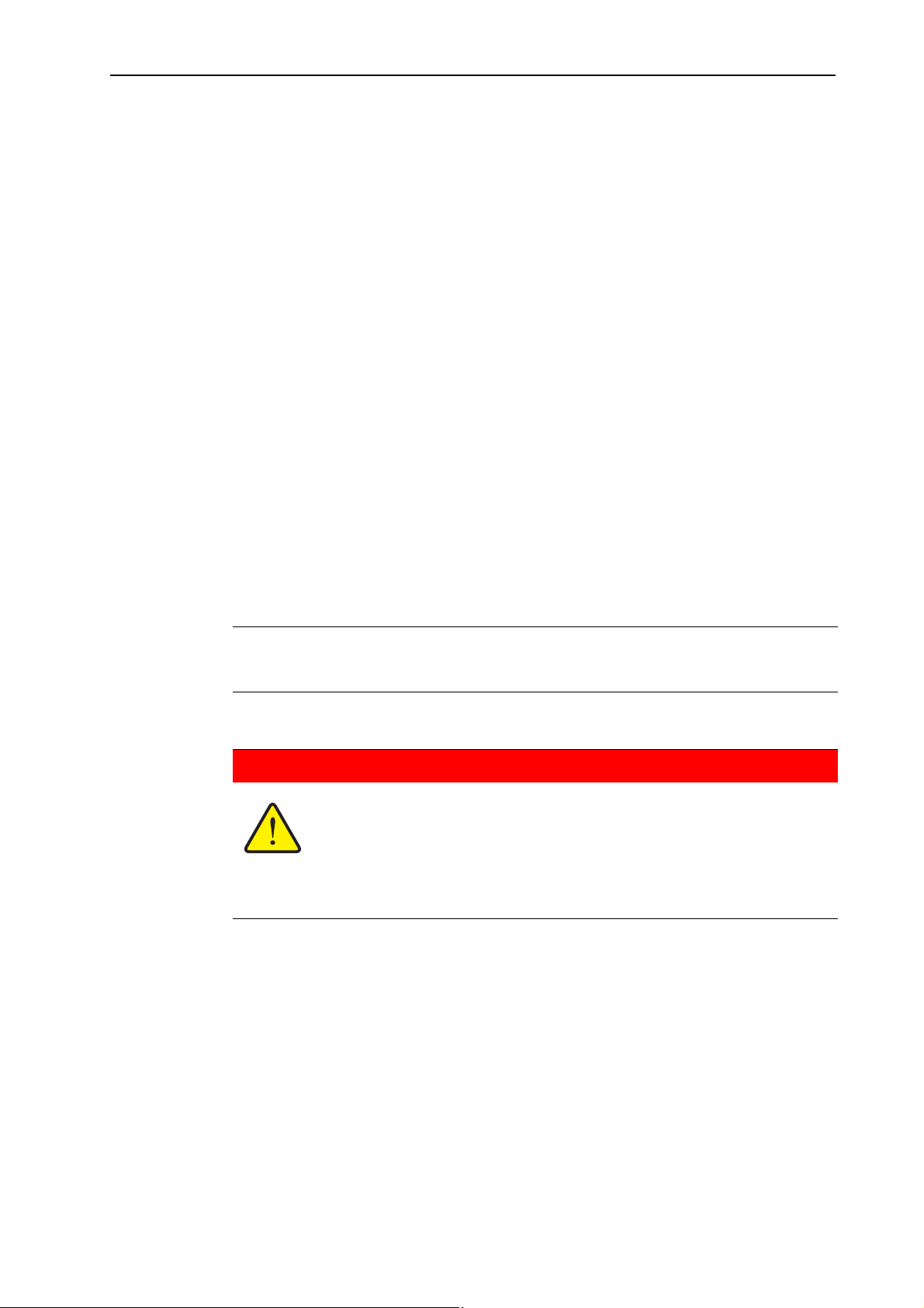
Signal word
Symbol Explanation
Example
n DANGER
Risk to life if warning is disregarded
Description of the danger and possible consequences.
Disregard of this warning can lead to the most extreme injury,
resulting in possible death.
Always take the specified measures to avoid this risk.
5
Safety 3
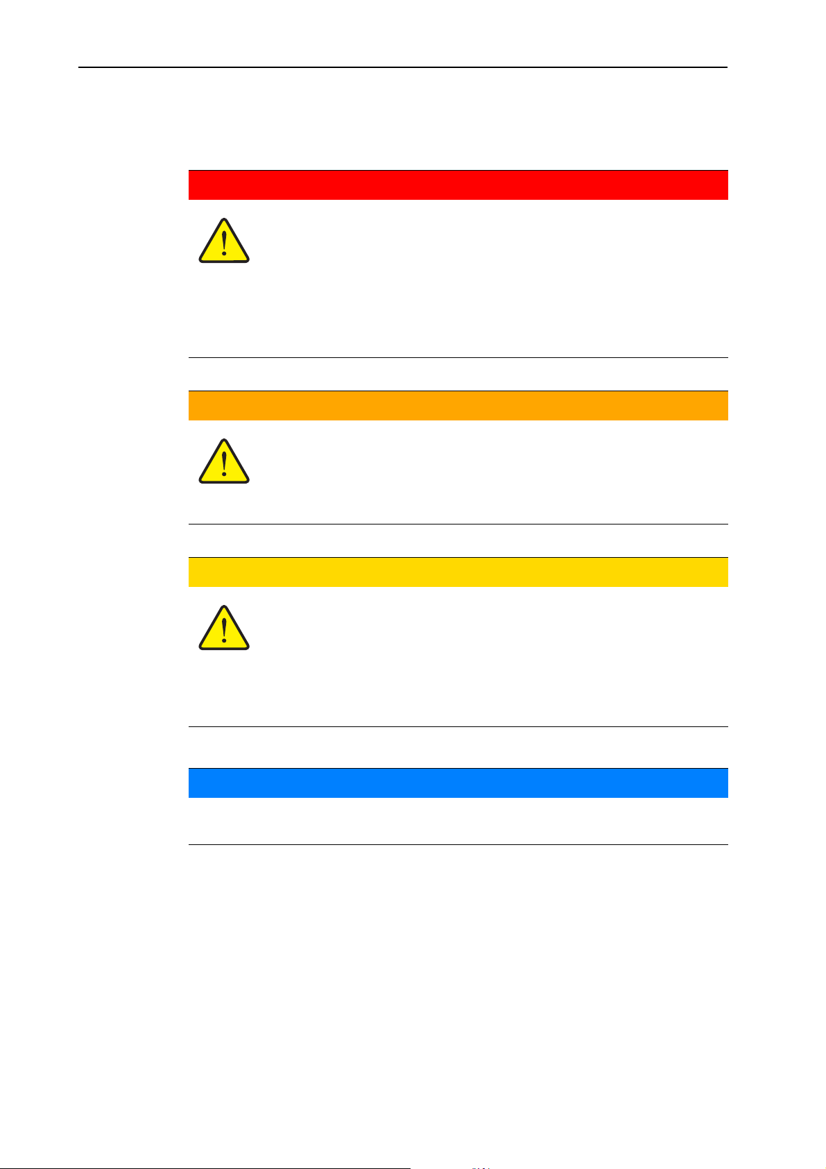
Warning severity level
The risk level is determined through the signal word. The risk levels are classified
as follows:
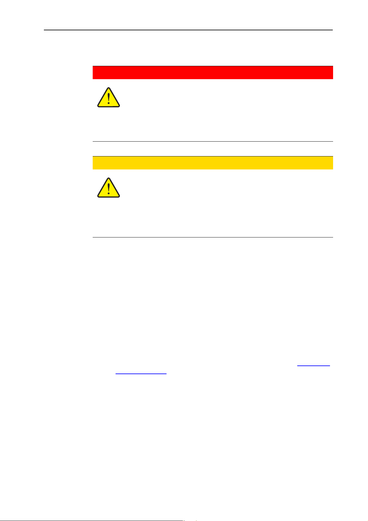
n DANGER
Type and source of danger
This is a warning against an immediate threat to the health and life
of persons.
Disregard of this warning can lead to the most extreme injury,
resulting in possible death.
Always observe the measures described to prevent this
danger.
n WARNING
Type of danger
This is a warning against possible danger to the health of persons.
Disregard of this warning can lead to severe injury.
Always take the specified measures to avoid this risk.
n CAUTION
Type of danger
This is a warning against possible danger for the health of persons
or damage to the environment and property.
Disregard of this warning can lead to injury as well as damage to
the product or the surrounding area.
Always take the specified measures to avoid this risk.
NOTICE
General instructions contain usage tips and particularly useful information but
no warnings.
6

3.3 General safety information
This solid fertiliser broadcaster of AXIS H EMC series is designed and manufactured to the state of the art in technology and the generally accepted rules of engineering. Nevertheless, operation and maintenance of the machine may pose a
risk to the life and limb of the operator or other persons, as well as cause damage
to the machine or other assets in the surrounding area.
Therefore operate the solid fertiliser broadcaster of AXIS H EMC series
Only when it is in a proper and roadworthy condition
In a safety-conscious and risk-aware manner.
This makes it imperative that you read and understand the contents of these operating instructions thoroughly. You must know the relevant accident prevention
measures as well as the generally recognised safety-related, occupational health
and road traffic laws and you must be a position to practically apply this knowledge as well.
3.4 Operator instructions
Safety
3
The owner is responsible for the designated use of the AXIS H EMC solid fertiliser broadcaster.
3.4.1 Personnel qualification
The personnel to be assigned the task of operating, maintaining and servicing the
sold fertiliser broadcaster must have read and understood the contents of the operating manual before using the product.
The machine should only be operated by trained and authorised personnel.
Personnel under training may work on the machine only if an experienced col-
league is present.
Maintenance and repair work must be carried out by appropriately qualified
persons.
3.4.2 Orientation
Sales representatives, factory representatives or employees of our company
KUHN will instruct the operator in the operation and maintenance of the solid fertiliser broadcaster.
It is the responsibility of the operating company to ensure that new or inexperienced operating or maintenance personnel thoroughly understand the contents
of this operator's manual before starting work on the machine.
7

Safety 3
3.4.3 Accident prevention
Safety and accident prevention regulations are regulated by law according to
each country. The owner of the machine is responsible for observing the regulations applicable in the country of operation.
The following instructions must also be observed:
Never leave the AXIS H EMC solid fertiliser broadcaster running without su-
pervision.
Do not ride on the AXIS H EMC solid fertiliser broadcaster while it is working
or being transported. (No passengers).
Do not use components of the AXIS H EMC solid fertiliser broadcaster as
steps to climb up onto the machine.
Do not wear loose clothing. Avoid workwear with belts, fringes or other parts
which can get caught in the machinery.
Follow the manufacturer's directions when working with chemicals. It may be
necessary to wear personal protective equipment.
3.5 Operating safety instructions
The solid fertiliser broadcaster should only be operated in a reliable condition to
avoid dangerous situations.
3.5.1 Parking the solid fertiliser broadcaster
Park the AXIS H EMC solid fertiliser broadcaster with an empty hopper on
level, form ground.
If the AXIS H EMC solid fertiliser broadcaster is parked alone (without a trac-
tor), the metering valve should be left completely open.
3.5.2 Filling the solid fertiliser broadcaster
Never fill the solid fertiliser broadcaster while the tractor engine is running.
Take the ignition key out to make sure the motor cannot be started.
Use suitable equipment for filling (e.g. front-end loader, auger).
Fill the solid fertiliser broadcaster no higher than the top. Check the filling lev-
el, e.g. through the viewing window in the container (depending on model).
Only fill the solid material broadcaster while in a attached state.
Only full the solid fertiliser broadcaster with the protective screen closed. This
way you will avoid operating problems caused by clumping of the grit or other
foreign bodies.
8

3.5.3 Inspection before startup
Before the first start and every subsequent operation, check the solid fertiliser
broadcaster to make sure that it is safe to operate.
Is all safety equipment on the solid fertiliser broadcaster installed and func-
tional?
Are all attachments and load bearing assemblies tight and in a proper condi-
tion?
Are the spreading discs and their fasteners in good condition?
Are the protective screens on the container closed and bolted?
Is the check gauge on the protective screen bolting device in the correct
zone? See figure 9.6
Are any persons in the danger zone of the solid fertiliser broadcaster?
3.5.4 During operation
If the solid fertiliser broadcaster malfunctions, stop the machine immediately
and lock it. Have the fault repaired immediately by qualified technicians.
on page 92.
Safety
3
Never climb up on to the solid fertiliser broadcaster when it is running.
Operate the solid fertiliser broadcaster only with the safety guard in the hop-
Rotating parts of the machine can cause severe injury. Therefore, always
Do not place any objects (such as screws, nuts) in to the spreader hopper.
Grit is flung from the machine at a high speed and can cause serious injury,
If the wind speed is too high, you should stop the spreading operation, as the
Never climb up on the solid fertiliser broadcaster or the tractor under power
3.6 Fertiliser
Improper selection or use of fertiliser may cause serious injury or environmental
damage.
per closed. The safety guard must not be opened or removed during operation.
make sure that body parts or items of clothing never come close to the rotating parts of the machine.
e.g. to the eyes. Make sure that there are no persons within the spreading
range of the solid fertiliser broadcaster.
spreading accuracy cannot be ensured.
lines.
When you choose a fertiliser, make sure you are properly informed about its
effects on humans, the environment and the machine.
Please note the fertiliser manufacturers instructions.
9

Safety 3
3.7 Hydraulics
The hydraulic system is under high pressure.
Fluid escaping under high pressure can cause serious injuries and environmental
damage. The following instructions must be observed to prevent danger:
The maximum allowed operating pressure should never be exceeded.
Release the pressure from the hydraulic system before all maintenance
When searching for leaks always wear safety glasses and safety gloves.
If injuries are caused by hydraulic oil consult a physician immediately, be-
When connecting the hydraulic hoses to the tractor hydraulics, make sure
The hydraulic hoses from the tractor and spreader should be connected with
Keep the hydraulic circuitry clean. Only hang the couplings in the brackets
work. Turn the tractor motor off and make sure it cannot be started during
maintenance work.
cause serious infections may result.
that the hydraulic system is depressurised.
the specified couplings only.
provided. Clean the connections before coupling.
Check the hydraulic components and hydraulic lines regularly for mechanic
defects, such as cuts and worn positions, crushing, cracking, porous sections
etc.
Pipes and pipe couplings undergo a natural aging process even if they are
stored and used properly. This is the reason their shelf and service life is limited.
The service life of the hose line should not exceed 6 years, including a storage
period of a maximum of 2 years.
The date of manufacture of the hose line is stamped on the hose coupling in
month and year
Replace the hydraulic pipes if they are damaged or old.
Replacement hydraulic lines must meet the technical requirements of the
equipment manufacturer. Pay particular attention to the maximum pressure
specifications of the pipes to be replaced.
10

3.8 Service and maintenance
During service and maintenance tasks, you have to take additional dangers into
account which cannot occur during normal operation.
Carry out the service and maintenance tasks carefully and with full concen-
tration. Always work with full awareness of the risks involved.
3.8.1 Maintenance personnel qualification
Welding and work on the electrical and hydraulic systems must be carried out
by qualified technicians only.
3.8.2 Parts subject to wear and tear
Observe the maintenance and repair intervals specified in this operator's
manual exactly.
Also observe the maintenance and repair intervals for the supplied compo-
nents. See the supplier documentation for the relevant intervals
We recommend having your dealer check the condition of the AXIS H EMC
solid fertiliser broadcaster, particularly fastening components, safety-relevant
plastic components, hydraulic system, metering components and spreader
vanes, after every working season.
Safety
3
Replacement parts should meet the minimum technical standards specified
by the manufacturer. The technical standards can be guaranteed by using
genuine replacement parts, for example.
Self-locking nuts are designed to be used only once. Always use new self-
locking nuts to fasten components (e.g. when replacing spreading vanes).
3.8.3 Service and repair tasks
Turn the tractor motor off before starting any cleaning, maintenance, repair or
service tasks. Wait for all rotating parts to come to a stop.
Make sure that no unauthorised person can switch on the solid fertiliser
broadcaster. Take out the tractor ignition key.
Check that the tractor is correctly parked with the solid fertiliser broadcaster.
Park the fertiliser spreader with an empty hopper on level, solid ground and
secure it to prevent it from moving.
Depressurise the hydraulic system before starting service or maintenance
work.
Disconnect the electrical system from the main power supply before starting
work on it.
Never clear blockages in the spreader hopper by hand or with the foot but al-
ways use a suitable tool. To prevent blockages always use the safety guard
when filling the hopper.
Before cleaning the fertiliser spreader with water, steam or other cleaning
agents cover all components that must be prevented from getting wet (e.g.
bearings, electrical connections).
Check the nuts and bolts regularly for tightness and tighten loose contacts.
11

Safety 3
3.9 Traffic safety
When travelling on public roads and tracks, the tractor with the attached solid fertiliser broadcaster must comply with the traffic regulations of the country in which
it is operating. The owner and driver are responsible for compliance with these
regulations.
3.9.1 Checks before driving
A pre-operational check is an important contribution to traffic safety. Before every
trip check compliance with the operating conditions, traffic safety and the regulations of the country of operation.
Make sure that the approved total weight is not exceeded. Note the permissi-
ble axle load, the approved braking load and the permissible tyre load capacity. See also "
Is the solid fertiliser broadcaster mounted correctly?
Could spreading material be lost while travelling?
- Check the fill level of the fertiliser in the hopper.
Axle load calculation" on page 29.
- The metering slides must be closed.
- The locks must also be closed on single-action hydraulic cylinders.
- Turn off electronic controls.
Check the tyre pressure and the function of the tractor brake system.
Do the lights and identification on the solid fertiliser broadcaster comply with
the national regulations for operation on public roads? Make sure to make the
fittings according to the regulations .
12

3.9.2 Road travel with the solid fertiliser broadcaster
The road handling and the tilting, steering and braking performance of the tractor
are all altered by the attached solid fertiliser broadcaster. For example, the high
permissible load capacity will reduce the weight on the front axle of the tractor and
may affect the steering.
Adjust your driving behaviour according to the load on the vehicle.
Always make sure you have unencumbered sight. If this is not possible (e.g.
while reversing), another person is required to direct the driver.
Do not exceed the legal speed limit.
Avoid sudden turns when driving uphill or downhill or across a slope. Due to
the change in the centre of gravity there is a risk of tipping over. Travel over
uneven, soft ground (e.g. entering a field, over road edges) with great care.
Set the lower link on the three-point linkage so it is rigid to prevent the ma-
chine from rocking.
Passengers are prohibited on the solid fertiliser broadcaster during transport
and operation.
Safety
3
13
Safety 3
3.10 Protective equipment built into the machine
3.10.1 Positioning of the protective equipment
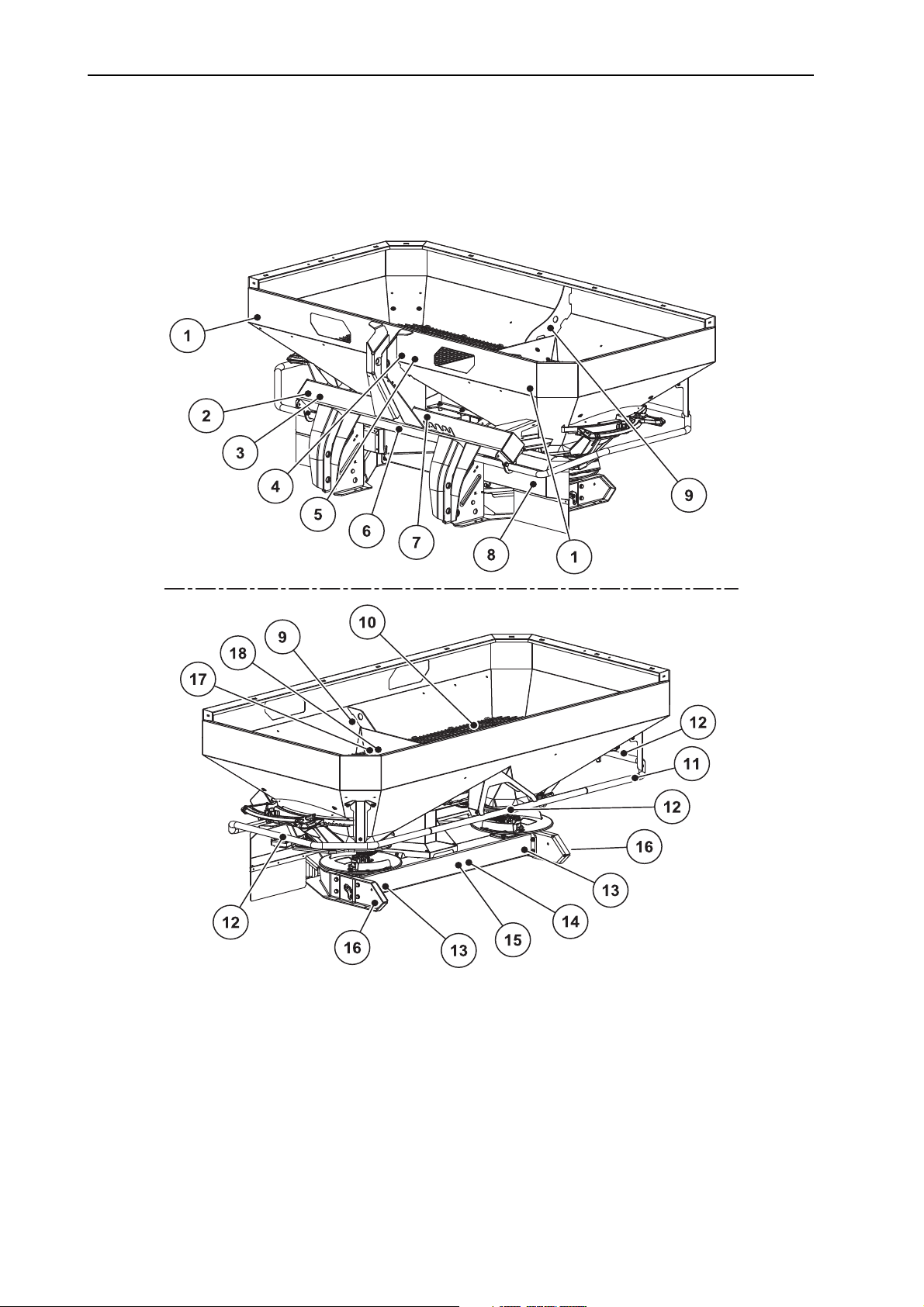
AXIS H 30.1 EMC, AXIS H 30.1 EMC + W
Figure 3.1: Position of protection devices, warning and instruction notices and reflectors
[1] White reflector in front
[2] Nameplate
[3] Serial number
[4] Warning: read operator's manual
[5] Material ejection warning
[6] KS/LS conversion
[7] Maximum payload warning
[8] Spreading disc cover
[9] Eyelet in hopper notice
14
[10] Protective screen in hopper
[11] Deflector bracket
[12] No-climbing notice
[13] Red reflector
[14] Warning: remove ignition key
[15] Moving parts warning
[16] Yellow side reflector
[17] Protective screen lock
[18] Instructions for protective screen lock

AXIS H 50.1 EMC + W
Safety
3
Figure 3.2: Position of protection devices, warning and instruction notices and reflectors
[1] White reflector in front
[2] Nameplate
[3] Serial number
[4] Warning: read operator's manual
[5] Material ejection warning
[6] KS/LS conversion
[7] Maximum payload warning
[8] Protective grid lock
[9] Instructions on going uphill
[10] Passenger transport prohibited warning
[11] Protective grid in hopper
[12] Instructions for protective grid lock
[13] Eyelet in hopper notice
[14] Spreading disc cover
[15] No-climbing notice
[16] Yellow side reflector
[17] Red reflector
[18] Moving parts warning
[19] Warning: remove ignition key
[20] Gear protective cover
[21] Deflector bracket
15

Safety 3
3.10.2 Protective device functions
The protective devices protect your life and limb.
Only operate the solid fertiliser broadcaster with effective protection devices.
Do not use the deflector bracket to climb up on the machine. It is not designed
for this. You may be in danger of falling.
Designation Function
Protective grid in the
hopper
Prevents the intake of body parts by the rotating agitator.
Prevents body parts from being cut off by the metering
slide.
Prevents faults caused by lumps in the spreading material, large stones or other large-scale objects (screening
effect) during the spreading process.
Protective grid lock Prevents the inadvertent opening of the protective grid
on the container. Engages mechanically if protective
grid is closed properly. Can be opened by using a tool.
Deflector bracket Protection against getting caught by the rotating spread-
ing discs from behind and from the side.
Spreading disc cover Protection against getting caught by the rotating discs
from the front.
Prevents the casting of fertiliser towards the front side
(in the direction of the tractor and driver).
16

3.11 Warning and instruction message stickers
The solid fertiliser broadcaster of the AXIS H EMC series has various warning
and instruction messages affixed to it. (For an illustration, please see figure 3.1
and figure 3.2
These warning and instruction messages are a part of the machine. They must
not be removed or modified. Missing or unreadable warning and instruction stickers must be replaced immediately.
If parts have been replaced with new ones, it should be made sure that the new
parts have the same warning and instruction stickers as the previous ones.
The correct warning and instruction notices can be obtained from the spare
parts service.
.)
NOTICE
Safety
3
17
Safety 3
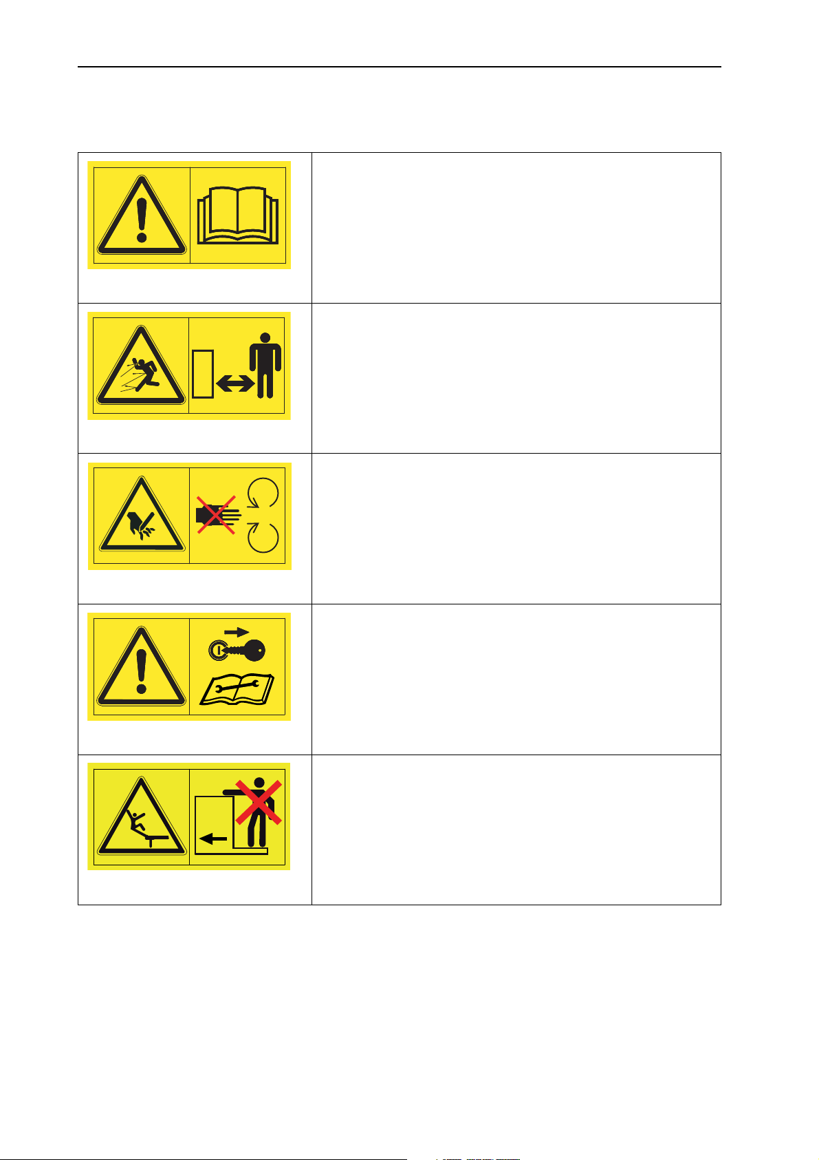
3.11.1 Warning stickers
Read instruction manual and warning messages.
Read and understand the instruction manual before operating the machine.
The operator's manual explains in detail how to operate the
spreader and contains valuable information on operation,
care and maintenance.
Danger through ejection of material
Risk of injury to the entire body through rapidly ejected
spreading material
Direct all persons out of the danger zone (spreading area) of
the solid fertiliser broadcaster before commissioning.
Danger from moving parts
Danger of amputation of body parts
Reaching into the danger areas of the rotating spreading
discs, the agitator or the drive shaft is prohibited.
Before carrying out repair and adjustment work, shut off engine and remove the key.
Remove the ignition key.
Before carrying out repair and maintenance work, shut off
engine and remove the key.
No carrying of people
Risk of slipping and injury. Do not climb on the steps of the
solid fertiliser broadcaster during spreading and transport.
18
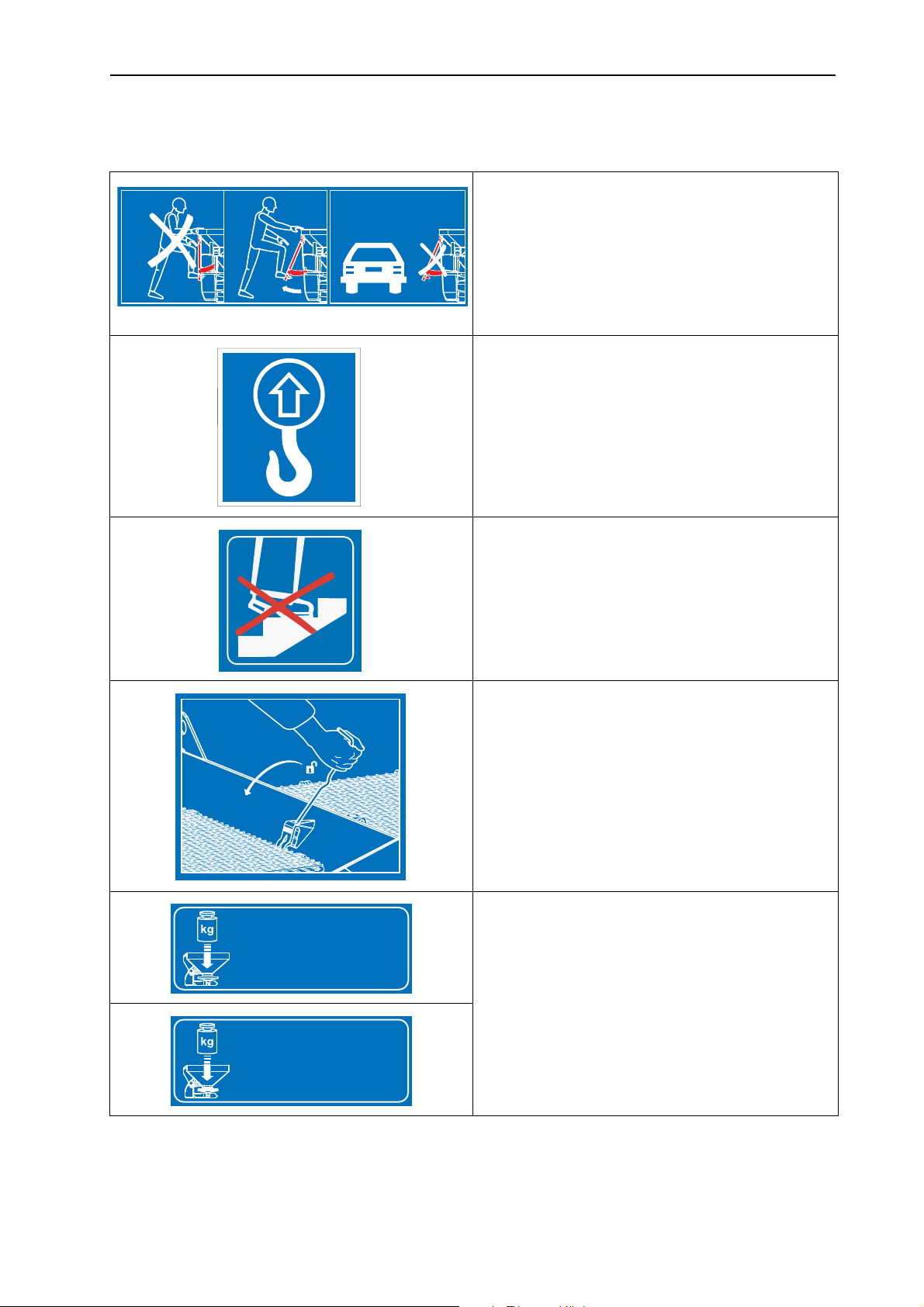
3.11.2 Instruction stickers and factory plate
2056545
2055689
3000 kg
2052173
max.
4000 kg
2056096
max.
Safety
Step
Climbing on the retracted steps is prohibited.
Only climb on the ladder when it is extended.
Only travel on the road with the ladder retracted.
Ring eyelets on the container
The brackets used for the fastening of the lifting
gear
3
Climbing prohibited
Climbing on the deflector bracket is prohibited.
Protective screen lock
The screen lock is automatically locked when
the protective screen on the container is closed
properly. It can only be unlocked by using a tool.
Maximum loading capacity (depending on model)
19

Safety 3
FABRIQUE POUR KUHN PAR RAUCH ( RFA )
KUHN S . A .
67700 SAVERNE - FRANCE
TYPE
N°
12345
KS/LS conversion
Tighten the setscrew as far as it will go, LS operation
Unscrew the setscrew as far as it will go, KS operation
Nameplate
Serial number
3.12 Reflectors
The solid fertiliser broadcaster of the AXIS H EMC series is factory fitted with
front, back and side identification (For an illustration of the positioning on the machine, see figure 3.1
and figure 3.2).
20

Technical data
4 Technical data
4.1 Machine information
4.1.1 Manufacturer
Manufacturer
KUHN SA
F-67706 Saverne Cedex
Tel.: +33 (0)3 88 01 81 00
Fax.: +33 (0)3 88 01 81 01
Internet: www.kuhn.com
4.1.2 Versions
Model AXIS H 30.1 EMC AXIS H 30.1 EMC + W AXIS H 50.1 EMC + W
4
Spreading speed, depending on travelling-
speed
Weighing cells
Electrical application point
adjustment
Speed regulation
EMC mass flow control
21

Technical data 4
4.1.3 Specifications of base equipment
Dimensions:
Data AXIS H 30.1
EMC
AXIS H
30.1 EMC + W
AXIS H
50.1 EMC + W
Overall width 240 cm 240 cm 290 cm
Overall length 141.5 cm 145.0 cm 161,0 cm
Fill height (basic machine) 101 cm 101 cm 125 cm
Distance of centre of gravity
65.5 cm 72.5 cm 74.5 cm
from lower link point
Fill width 230 cm 230 cm 270 cm
Working width
1
12 - 42 m 12 - 42 m 18 - 50 m
Capacity of basic container 1,200 l 1,200 l 2,000 l
Mass flow
2
max. 500 kg/min 500 kg/min 500 kg/min
Hydraulic pressure max. 210 bar 210 bar 210 bar
Hydraulic output 50l/min 50l/min 65l/min
Noise level
(measured in
75 dB (A) 75 dB (A) 75 dB (A)
3
the closed tractor driver's
cab)
1. Working width dependent on fertiliser and casting disc type
2. Max. mass flow dependent on fertiliser type
3. Since the noise level of the solid fertiliser broadcaster can only be determined when the tractor
is running, the actual measured value is greatly dependent on the tractor type being used.
Weights and loads:
NOTICE
The unladen weight (mass) of the solid fertiliser broadcaster varies depending
on how it is equipped and the combination of attachments. The unladen weight
(mass) shown on the factory plate refers to the standard version.
Data AXIS H 30.1
EMC
AXIS H 30.1
EMC + W
AXIS H 50.1
EMC + W
Unladen weight 340 kg 400 kg 700 kg
Payload max. 3,000 kg 4,000 kg
22

Technical data
4.1.4 Specifications of attachments and attachment combinations
Solid fertiliser broadcastersof AXIS H EMC series can be operated with different
attachments and combinations of attachments. Depending on the feature package the capacity, dimensions and weights may change.
NOTICE
The combination of attachments must be chosen so that the max. loading capacity is not exceeded.
AXIS H 30.1 EMC, AXIS H 30.1 EMC + W
Attachment combination L603 L800 L1500 XL1103 XL1300 XL1800
Change in capacity + 600 l + 800 l + 1500 l + 1100 l + 1300 l + 1800 l
Change in fill height 0 + 26 cm + 50 cm + 24 cm + 38 cm + 52 cm
4
Attachment size max. 240 x 130 cm 280 x 130 cm
Attachment weight 30 kg 45 kg 75 kg 60 kg 65 kg 85 kg
Notes 3-side 4-side 4-side 3-side 4-side 4-side
AXIS H 50.1 EMC + W
Attachment combination GLW1000 GLW2000
Change in capacity + 1000 l + 2000 l
Change in fill height + 22 cm + 44 cm
Attachment size max. 290 x 150 cm
Attachment weight 52 kg 86 kg
Notes 4-side 4-side
23

Technical data 4
4.2 List of available optional equipment
We recommend that you have the extra equipment fitted and mounted on the
basic machine by your supplier or an authorised service centre .
4.2.1 Extensions
The holding capacity of the spreader can be increased by extending the main
container by an attachment hopper.
The extensions are bolted to the standard unit.
For an overview of extensions and extension combinations see Chapter
4.1.4:
Specifications of attachments and attachment combinations, page 23.
NOTICE
NOTICE
4.2.2 Hopper covers
A hopper cover can be installed to protect the spreader material from rain and
moisture.
The hopper covers are screwed both to the main hopper and to the hopper extension.
Hopper covers Application
AP-L 25, foldable
AP-XL 25, foldable Extensions: XL11031, XL1300, XL1800
AP-L 50, foldable
1. A supplementary hopper tarpaulin is necessary for this attachment.
4.2.3 Hopper tarpaulin supplement
For the attachments L603 and XL1103, a supplementary tarpaulin is necessary
in addition to the container tarpaulin.
Standard unit
Extensions: L603
Extensions: GLW1000, GLW2000
1
, L800, L1500
24
Tarpaulin supplements Application
APE-L 25, foldable
APE-XL 25, foldable
Extension: L603
Extension: XL1103

4.2.4 Auxiliary lighting
The solid fertiliser broadcaster can be fitted with additional lighting.
Lighting Application
Technical data
4
BLO 25/50
BLW 20/25/50
BLF 25/50
BLF
Attachments are subject to the lighting regulations specified in the traffic regulations. Observe the traffic regulations of your country.
4.2.5 ASR 25 parking rollers with bracket
Lighting for rear
without warning sign
Lighting for rear
with warning sign
Lighting for front
with warning sign
for wide attachments
Lighting for front
without warning sign
for wide attachments
NOTICE
For parking and manually moving the empty fertiliser broadcaster.
The parking rollers consist of two turning wheels in front and two non turning
wheels at the rear without wheel lock
4.2.6 Border spreading device GSE 25
This option is only available for the AXIS H 30.1 EMC and
AXIS H 30.1 EMC + W.
Limits the spreading width (either towards the left or right) to the range between
approx. 0.5 m and 2 m from the centre of the tractor track to the outer edge of the
field. The metering slide that points to the field edge is closed.
Fold the border spreading unit downwards for border spreading.
The border spreading unit must be hinged up again before two-sided spread-
ing.
NOTICE
25

Technical data 4
4.2.7 Hydraulic remote control FHZ for GSE 25
NOTICE
This option is only available for the AXIS H 30.1 EMC.
This remote controller is used, from the tractor cab, to hydraulically swing the
GSE 25 border spreading unit into position or to swing it from border spreading
position to the both side spreading position.
For operating the hydraulic remote controller FHZ 25, a single action valve is required
4.2.8 Hydraulic remote control FHZ 26 for GSE 25
NOTICE
This option is only available for the AXIS H 30.1 EMC + W.
This remote controller is used, from the tractor cab, to hydraulically swing the
GSE 25 border spreading unit into position or to swing it from border spreading
position to the both side spreading position.
For operating the hydraulic remote controller FHZ 26, a single action valve is required.
4.2.9 Dirt deflector extension SFG-E 30
This option is only available for the AXIS H 30.1 EMC and
AXIS H 30.1 EMC + Wr.
If the deflector SFG 30 does not perform satisfactorily, the SFG-E 30 extension
can be mounted additionally.
4.2.10 Spreading vane set Z14, Z16, Z18
This set of spreading vanes is used for spreading snail bait. The snail bait spreading vane replaces the short spreading vane on the right and left spreading discs.
NOTICE
Set Application
Z14
Z16
Z18
4.2.11 Inspection kit PPS5
For checking cross-distribution in the field.
26
Spreading disc S4
Spreading disc S6
Spreading disc S8

4.2.12 Fertiliser Identification System DiS
Rapid, uncomplicated determination of spreader settings with unfamiliar fertilisers.
4.2.13 Hydraulic pressure filter
For long, error-free operation of hydraulic components.
Technical data
4
27

Technical data 4
28

5 Axle load calculation
G
T
T
G
V
V
H
H
abcd
Danger of overloading
Mounted units on the front or rear three-point linkage must not
cause the approved total weight to be exceeded. The front axle of
the tractor must always be loaded with at least 20 % of the
unladen weight of the tractor.
Before using the unit make sure that it meets these require-
Axle load calculation
n CAUTION
ments by performing the following calculations or weighing
the tractor-unit combination
5
Calculation of the total weight,
the axle loads and the tyre capacity and the required ballast
weights.
Figure 5.1: Loads and weights
You will need the following data for the calculation:
Character [unit]
T
[kg] Empty weight of tractor [1]
L
T
[kg] Front axle load on the empty tractor [1]
V
[kg] Rear axle load on the empty tractor [1]
T
H
[kg] Total weight of front-mounted unit or front ballast [2]
G
V
[kg] Total weight of rear-mounted unit or rear ballast [2]
G
H
a [m] Distance between centre of gravity of front-mounted
Meaning Calculation by
(table footer)
[2], [3]
unit or front ballast and centre of front axle
b [m] Tractor wheelbase [1], [3]
c [m] Distance between centre of rear axle and centre of
d [m] Distance between centre of lower link ball and cen-
[1] See tractor operator's manual
[2] See equipment price list and/or operator's manual
[3] Measuring
[1], [3]
lower link ball
[2]
tre of gravity of rear-mounted unit or rear ballast
29

Axle load calculation 5
G
Vmin
G
H
cd+()• TVb02TLb••,+•–()
ab+
---------------------------------------------------------------------------------------------=
G
Hmin
GVa• THb 0 45 TLb••,+•–()
bcd++
----------------------------------------------------------------------------------=
T
Vtat
G
V
ab+()• TVbG
H
– cd+()••+()
b
-------------------------------------------------------------------------------------------=
G
tat
GVTLG
H
++()=
Rear-mounted unit or front-rear combinations
Calculation of minimum ballast at
front G
V min
Enter the calculated minimum ballast requirement in the table.
Front-mounted unit
Calculation of the minimum ballast at
rear G
H min
Enter the calculated minimum ballast requirement in the table.
(If the front-mounted unit (
GV) is lighter than the minimum ballast at the front (GV min
), the weight of the front-
mounted unit must be increased to at least the weight of the minimum front ballast.)
Calculation of the actual front- axle
load T
V tat
Enter the calculated actual and approved front-axle load as specified in the tractor operator's
manual in the table.
If the rear-mounted unit (GH) is lighter than the minimum ballast at the rear (G
), the weight
Hmin
of the rear-mounted unit must be increased to at least the weight of the minimum rear ballast.
Calculation of the actual total weight
G
tat
Enter the calculated actual and approved total weight as specified in the tractor operator's manual
in the table.
30

Axle load calculation
T
H
tat
G
tatGVtat
–()=
Calculation of the actual rear-axle
load T
H tat
Enter in the table the actual calculated rear axle load and the permissible rear axle load specified
in the tractor operating instruction.
Tyre load capacity
Enter double the value (two tyres) of the approved tyre load capacity (for example, see tyre manufacturer's documentation) in the table.
Axle load table:
5
Minimum ballast
Actual value from
calculation
kg ⎯⎯
Reliable value according to operator's manual
Twice approved
tyre load capacity
(two tyres)
front/rear
Total weight kg ≤ kg ⎯
Front-axle load kg ≤ kg ≤ kg
Rear-axle load kg ≤ kg ≤ kg
The minimum ballast weight must be mounted on the tractor as an attachment or as ballast!
The calculated values must be less than or equal to the permitted values.
31

Axle load calculation 5
32

6 Transport without tractor
6.1 General safety instructions
Before transporting the solid fertiliser broadcaster observe the following
instructions:
The solid fertiliser broadcaster is not allowed to be transported with an empty
hopper without a tractor.
The operation must only be carried out by suitable, trained and expressly au-
thorised personnel.
Suitable means of transportation and lifting equipment (e.g. crane, fork lift
truck, cable devices ...) are to be used for transport purposes.
Establish the transportation route in good time and remove possible obsta-
cles.
A check must be made to ascertain that all safety and transport devices are
fit for operation.
Secure all danger zones even if the risk is short lived.
Transport without tractor
6
The person responsible for the transport must ensure that the solid fertiliser
broadcaster will be transported correctly.
Unauthorised persons are to be kept away from the transport route. The are-
as concerned must be cordoned off.
The solid fertiliser broadcaster must be handled and transported carefully.
Make sure that allowance is made for the centre of gravity. If necessary, ad-
just the cables such that the machine is correctly aligned on the means of
transport.
Transport the solid fertiliser broadcaster to the final destination as close to the
ground as possible.
6.2 Loading and unloading, parking
1. Determine the weight of the solid fertiliser broadcaster.
Details are provided on the nameplate.
If applicable, also note the weight of possible accessories and attachments.
2. Hang suitable lifting cables in both ring eyelets.
3. Carefully raise the machines with suitable hoisting gear.
4. Carefully set the machine down on the loading pallet of the transport vehicle
on a stable ground surface.
33

Transport without tractor 6
34

7 Before operation
7.1 Handing over the solid fertiliser broadcaster
When taking delivery of the solid fertiliser broadcaster, check to make certain the
scope of delivery is complete.
The standard equipment includes
1 solid fertiliser broadcaster of AXIS H EMC series
1 AXIS H EMC operator's manual
1 calibration chart (paper or CD)
1 calibration kit comprising chute and calculator
Lower link and upper link pins
1 spreading disc set (according to order)
Please check any special equipment that you ordered.
Check and make sure that no damage occured to the machine during transport
and that no parts are missing. Have the transport damages confirmed by the
transport company.
Before operation
7
In case of doubt, please contact your dealer or our factory.
7.2 Tractor requirements
To ensure safe, proper use of the MDS solid fertiliser broadcaster of the
AXIS H EMC series, the tractor must meet the necessary mechanical, hydraulic
and electrical requirements.
Oil supply: max. 210 bar, single or double-acting valve (depending on equip-
ment)
Hydraulic output, depending on machine type: 50-65l/min, constant flow or
load sensing system
Free backflowmin. NW 18 mm
Electrical system: 12 V
Three point linkage category II.
35

Before operation 7
7.3 Mounting the solid fertiliser broadcaster to the tractor
7.3.1 Requirements
n DANGER
Danger from unsuitable tractor
Use of an unsuitable tractor for the solid fertiliser broadcaster of
the AXIS H EMC series can lead to the severest possible accidents during operation and transport.
Only tractors that meet the technical requirements for the solid fertiliser broadcaster may be used.
Check the vehicle documentation to make sure that your
tractor is suitable for the solid fertiliser broadcaster of the
AXIS H EMC series.
Check the following points in particular:
Are both the tractor and solid fertiliser broadcaster safe to operate?
Does the tractor comply with the mechanical, hydraulic and electrical require-
ments? (See „
Do the attachment categories of the tractor and solid fertiliser broadcaster
Tractor requirements“ on page 35).
match? (If necessary, consult with your dealer)
Is the solid fertiliser broadcaster standing securely on flat, firm ground?
Do the axle loadings conform to the stipulated calculations (see
„
Axle load calculation“ on page 29)?
36

7.3.2 Attachment
The solid fertiliser broadcaster is attached to the three-point linkage (rear power
lift) of the tractor.
Before operation
n DANGER
Danger of crushing between the tractor and the solid fertiliser
broadcaster
Persons present between the tractor and the solid fertiliser
broadcaster and the when the tractor is approaching or when the
hydraulics are actuated are risking their lives.
The tractor may brake too late or not at all because of inattention
or faulty operation.
Make sure that no one stands between the tractor and the
solid fertiliser broadcaster.
7
NOTICE
For normal fertilisation and late fertilisation always use the upper couplings of
the solid fertiliser spreader. See figure 7.1
.
Figure 7.1: Mounting position
37

Before operation 7
1 2 3 4 5
Mounting instructions:
The machine can be connected to the tractor with class III linkage only with
class II clearance and the use of reducing sleeves.
The bottom and top linkage pins must be locked with the locking pins or spring
clips.
The solid fertiliser broadcaster must be mounted as specified in the calibra-
tion charts for correct cross distribution of the fertiliser.
To avoid a seesawing motion during operation, make sure that the solid ferti-
liser broadcaster does not have too much sideways play:
- Lower steering arms of the tractor should be braced by stabilising struts
or chains.
1. Start the tractor.
2. Approach the solid fertiliser broadcaster with the tractor.
Do not latch the lower steering arm hooks into place yet.
Make sure there is enough space between the tractor and the solid ferti-
liser broadcaster to be able to connect the drive shaft and control elements.
3. Turn off the tractor. Remove the ignition key.
NOTICE
The solid fertiliser broadcaster can be connected to different hydraulic systems.
Hydraulic system with constant flow pump
Hydraulic system with regulating pump without external load sensing connec-
tion
Hydraulic system with regulating pump with external load sensing connection
Figure 7.2: Connection lines, solid fertiliser broadcaster
[1] Free backflow
38
[2] Pressure line
[3] LS pipe
[4] ISOBUS device connector
[5] Light cable

Before operation
NOTICE
The couplings of the hydraulic hoses are colour coded and positive. Always
connect the hoses according to colour and suitability.
The connections and coupling heads of the cables must be clean.
7
4. Connect the free return hose (figure 7.2
(figure 7.2
position 2) and the LS line (figure 7.2 position 3) with the relevant
position 1), the pressure line
couplings on the tractor.
5. Connect the ISOBUS device connector (figure 7.2
position 4) to the ISOBUS
connector socket on the rear of the tractor.
6. Connect the lighting cable (figure 7.2
position 5).
NOTICE
An electronic slide control is connected to the AXIS H EMC solid fertiliser broadcaster.
The electric slide actuator is described in a separate operator's manual for the
electronic control system. This operator's manual is part of the electronic control
system.
7. From the tractor cab, couple the lower steering arm hook and the upper steering arm to the retainers provided for them, as described in the operator's manual for your tractor.
NOTICE
We recommend using lower arm hooks with a hydraulic upper arm for safety
and comfort. See figure 7.1
.
8. Check that the solid fertiliser broadcaster is securely fixed in position.
9. Raise the solid fertiliser broadcaster carefully to the maximum lifting height.
10. Preset mounting height according to the spreader settings chart. See
7.7.2:
Settings as per calibration chart, page 51.
39

Before operation 7
7.4 Preset the mounting height
7.4.1 Safety
Danger of being crushed under falling spreader
If the two halves of the upper steering arm are brought fully apart
from each other by mistake, the steering arm may not be able to
compensate for the weight of the full load of the fertiliser resulting
in the solid fertiliser broadcaster from abruptly falling over or falling
over backwards.
Persons can be seriously hurt and the machine damaged.
If you want to extend the upper steering arm, please always
take the maximum allowed extension length given by the
tractor or steering arm manufacturer into account.
Clear the area of any persons who might be present in the
danger zone of the solid fertiliser broadcasters.
n DANGER
n WARNING
Risk of injury from rotating machine components
Contact with the spreading equipment (spreading discs, spreading
vanes) may injure, crush or cut off body parts. Body parts or
objects may be caught and pulled in.
Never exceed the maximum approved hopper heights at
the front (V) and rear (H).
General instructions before setting the mounting height
We recommend that you choose the highest coupling point on the tractor to
connect the upper steering arm to, particularly for high lifting heights.
NOTICE
For normal fertilisation and late fertilisation always use the upper couplingsof
the solid fertiliser spreader.
The lower coupling points on the solid fertiliser broadcaster which are meant
for the lower steering arms of the tractor should only be used be used in
exceptional circumstances during late fertilisation.
40

Before operation
V
H
7.4.2 Maximum approved hopper mounting height at front (V) and rear (H)
The maximum approved hopper height (V + H) is measured from the ground
to the bottom edge of the frame.
7
Figure 7.3: Maximum approved hopper mounting height V and H during nor-
mal and late fertilisation
The maximum approved hopper height depends on the following factors:
Normal or late fertilisation.
Spreader equipment Maximum approved hopper mounting height
during normal fertilisation
V [mm] H [mm] V [mm] H [mm]
AXIS H 30.1 EMC
AXIS H 30.1 EMC + W
AXIS H 50.1 EMC + W 990 990 900 960
1040
1040
during late fertilisation
950 1010
41

Before operation 7
7.4.3 Hopper mounting heights A and B as per the spreading calibration chart
The hopper heights in the calibration chart (A and B) are always measured in the
field from the top of the crop height to the bottom edge of the frame.
NOTICE
The values of A and B are taken from the calibration charts.
Setting the mounting height during normal fertilisation
Requirements:
The solid fertiliser spreader should be connected to the tractor at the highest
pivoting point of the steering arm.
The lower arm of the tractor should be connected to the upper coupling
point of the solid fertiliser broadcaster.
Proceed as follows when determining the hopper height (in normal dressing):
1. Determine the hopper heights A and B (above crop) from the calibration
chart.
2. Compare the hopper heightsA and B (plus the crop height) with the maximum
approved hopper mounting heights at the front (V) and rear (H).
42

Before operation
7
Figure 7.4: Mounting position and height during normal fertilisation
The following applies:
AXIS H 30.1 EMC,
AXIS H 30.1 EMC + W AXIS H 50.1 EMC + W
A + crop height ≤ V Max. 1040 mm Max. 990 mm
B + crop height ≤ H Max. 1040 mm Max. 990 mm
3. If the maximum approved mounting height of the solid fertiliser broadcaster is
exceeded or the mounting heights A and B cannot be reached, then the solid
fertiliser broadcaster sould be mounted according to late fertilisation calibration values.
43

Before operation 7
Setting the mounting height during late fertilisation
Requirements:
The solid fertiliser spreader should be connected to the tractor at the highest
pivoting point of the tractor.
The lower arm of the tractor should be connected to the upper lower cou-
pling point of the solid fertiliser broadcaster.
Proceed as follows when determining the hopper mounting height (during late fertilisation):
1. Determine the hopper mounting heights A and B (above crop) from the calibration chart.
2. Compare the hopper heights A and B (plus the crop height) with the maximum approved hopper mounting heights at the front (V) and rear (H).
44
Figure 7.5: Mounting position and height during late fertilisation
The following applies:
AXIS H 30.1 EMC,
AXIS H 30.1 EMC + W AXIS H 50.1 EMC + W
A + crop height ≤ V Max. 950 mm Max. 900 mm
B + crop height ≤ H Max. 1010 mm Max. 960 mm

Before operation
3. If the lifting height of the tractor is not enough to be able to set the required
mounting height, you can use the lower coupling point on the lower arm of the
solid fertiliser spreader.
NOTICE
Make sure that the maximum allowed length of the upper arm is not exceeded.
Please note the instructions in the operating manuals of the tractor and
steering arm.
7
Figure 7.6: Solid fertiliser broadcaster mounted to the lower coupling point of
the lower steering arm
The following applies:
AXIS H 30.1 EMC,
AXIS H 30.1 EMC + W AXIS H 50.1 EMC + W
A + crop height ≤ V Max. 950 mm Max. 900 mm
B + crop height ≤ H Max. 1010 mm Max. 960 mm
45

Before operation 7
7.5 Using the step
Always keep in mind that troubleshooting involves additional hazards in case you
are climbing into the hopper container.
Use the step with extra care. Work very carefully and with awareness of danger.
Observe the following instructions in particular:
Turn tractor motor off and wait till all moving parts have stopped moving. Take
the ignition key out.
Use the step only when the solid fertiliser broadcaster is lowered.
Use the step only if it is folded out.
Do not climb over the container tarpaulin into the container.
Use the handle on the container tarpaulin.
Do not climb into a filled up container.
n DANGER
Danger of injury from moving parts in the hopper
There are moving parts in the hopper.
The rotating agitator can cause injury to hands and feet.
Turn off agitator.
Climb into the container only for troubleshooting purposes.
Safety screen should be opened only for maintenance or
repair work.
46

Folding out step
Before folding out step:
Turn off tractor motor.
Lowering the solid fertiliser spreader.
1. Lift the step at the bottom
and fold it inwards.
2. Lower the step to the stop
while it is in the folded position.
Before operation
7
1. Lift the step at the bottom
and fold it out.
2. Lock it into an open position.
Figure 7.7: Step AXIS 30.1 EMC
Figure 7.8: Step AXIS 50.1 EMC
47

Before operation 7
Folding in the step
NOTICE
The step must be folded up before each ride and during spreading operation.
1. Lift the step at the bottom
and fold it upwards.
2. Lock it into a closed position.
1. Lift the step at the bottom
and fold it inwards.
2. Lock it into a closed position.
Figure 7.9: Step AXIS 30.1 EMC
Figure 7.10: Step AXIS 50.1 EMC
48
7.6 Filling the solid fertiliser broadcaster
n DANGER
Danger from running engine
Working on the solid fertiliser broadcaster with the engine running
may cause serious injuries from the mechanical components and
escaping fertiliser.
Never fill the solid fertiliser with the tractor engine running.
Turn off tractor. Remove the ignition key.
n CAUTION
Excessive total weight.
If the approved total weight is exceeded, it will affect the operating
and traffic safety of the vehicle (and tractor) and may cause serious damage to the machine and environment.
Before operation
7
Before filling up, please determine the possible volume that
can be filled.
Do not exceed the approved maximum total weight.
Notes on filling the solid fertiliser broadcaster:
Park the solid fertiliser broadcaster on even, solid ground only.
Fill the solid fertiliser broadcaster only when attached to the tractor. Make
sure that the tractor is standing on flat, firm ground.
Secure the tractor to prevent movement. Set handbrake.
Shut off the engine of the tractor. Remove the ignition key.
For filling levels above 1.25 m, use special equipment (e.g. front loader,
screw conveyor).
Fill the solid fertiliser broadcaster no higher than the top.
Check the fill level either by climbing up on the folded-down step or by looking
through the inspection window in the hopper container.
- Please refer to the climbing instructions given in the chapter „
Using the
step“ on page 46.
49

Before operation 7
Fill level scale
A fill level scale is installed in the hopper to monitor the starting weight.
The scale can be used to estimate how long spreading can continue before the
hopper must be refilled.
The fill level can be checked through two inspection windows in the side of the
hopper.
Figure 7.11: Fill level scale
[1] Inspection window
[2] Fill level scale (graduated in litres)
[3] Protective grid in hopper
50

7.7 Using the calibration charts
7.7.1 Information on the calibration chart
The values in the spreading charts have been determined on the solid fertiliser
broadcaster test installation.
The fertilisers used have been procured from fertiliser manufacturers or from storage depots. Experience shows that your spreading materials - even with identical
specifications - may have different spreading properties because of storage,
transport and many other reasons.
This means that the solid fertiliser spreading settings specified in the fertiliser
charts may result in a different spreading amount and a poorer fertiliser distribution.
Therefore observe the following instructions:
Check the working width of the fertiliser distribution with a practice test kit (op-
tion).
Use only fertilisers listed in the spreading calibration charts.
Before operation
7
Please contact us if you do not find a particular fertiliser type mentioned in the
calibration charts.
Follow the settings exactly. Even a slightly incorrect setting may adversely af-
fect the spreading pattern.
When using urea note particularly the following:
Because of fertiliser imports, urea is available in widely varying qualities and
particle sizes. This may make different spreader settings necessary.
Urea is more sensitive to wind and absorbs more moisture than other fertilis-
ers.
The operator is responsible for making the correct settings according to the fertiliser in use.
We point out specifically that we do not accept any liability for damage resulting
from incorrect spreader settings.
7.7.2 Settings as per calibration chart
Depending on fertiliser type, working width, application rate, ground speed and
fertilisation method, the operator determines the hopper mounting height, fertiliser drop point, metering slide adjustment, and PTO speed for optimum spreading
from the calibration chart.
NOTICE
51

Before operation 7
Example of spreading during normal fertilisation
Figure 7.12: Spreading during normal fertilisation
Field spreading in normal fertilisation yields a symmetrical scatter pattern. If the
spreader is correctly set (see information in the calibration charts), the fertiliser is
spread evenly over the field.
Specified parameters:
Types of fertiliser: KAS BASF
Application rate: 300 kg/ha
Working width: 24 m
Ground speed: 12 km/h
The following settings on the solid fertiliser broadcaster are required according to
the fertiliser charts:
Hopper height: 50/50 (A = 50 cm, B = 50 cm)
Fertiliser drop point: 6
Metering slide adjustment: 180
Spreading disc type: S4
Spreading disc speed: 900 rpm
52

Before operation
Example of boundary spreading in normal fertilisation
Figure 7.13: Environmentally optimised boundary spreading in normal
fertilisation
During boundary spreading in normal fertilisation, almost no fertiliser goes beyond the field boundary. Underfertilisation at the field boundary must be accepted
in this case.
Specified parameters:
7
Types of fertiliser: KAS BASF
Application rate: 300 kg/ha
Working width: 24 m
Ground speed: 12 km/h
The following settings on the solid fertiliser broadcaster are required according to
the fertiliser charts:
Hopper height: 50/50 (A = 50 cm, B = 50 cm)
fertiliser drop point: 6
Metering slide adjustment: 180 left, 150 right
Spreading disc type: S4
Spreading disc speed: 900 rpm
Border spreading speed: 600 rpm
1. Recommended volume reduction of 20% on boundary spreading side
1
53

Before operation 7
Example of yield-optimised boundary spreading in normal fertilisation:
Figure 7.14: Yield-optimised boundary spreading in normal fertilisation
Yield-optimised boundary spreading in normal fertilisation refers to a spreading
technique in which a bit more fertiliser lands beyond the boundary of the field.
Therefore, there is just a slight underfertilisation at the field boundary.
Specified parameters:
Types of fertiliser: KAS BASF
Application rate: 300 kg/ha
Working width: 24 m
Ground speed: 12 km/h
The following settings on the solid fertiliser broadcaster are required according to
the fertiliser charts:
Hopper height: 50/50 (A = 50 cm, B = 50 cm)
fertiliser drop point: 6
Metering slide adjustment: 180
Spreading disc type: S4
Spreading disc speed: 900 rpm
Border spreading speed: 600 rpm
54

Before operation
Example of field spreading in late top fertilisation
Figure 7.15: Field spreading in late top fertilisation
Field spreading in late fertilisation yields a symmetrical spreading pattern. If the
spreader is correctly set (see information in the calibration charts), the fertiliser is
spread evenly over the field.
Specified parameters:
Types of fertiliser: KAS BASF
7
Application rate: 150 kg/ha
Working width: 24 m
Ground speed: 12 km/h
The following settings on the solid fertiliser broadcaster are required according to
the fertiliser charts:
Hopper height: 0/6 (A = 0 cm, B = 6 cm)
Fertiliser drop point: 6.5
Metering slide adjustment: 90
Spreading disc type: S4
Spreading disc speed: 900 rpm
55

Before operation 7
Example of environmentally optimized boundary spreading in late top fertilisation:
Figure 7.16: Environmentally optimised boundary spreading in delayed top fer-
tilisation
During boundary spreading in normal fertilisation, almost no fertiliser goes beyond the field boundary. Underfertilisation at the field boundary must be accepted
in this case.
Specified parameters:
Types of fertiliser: KAS BASF
Application rate: 150 kg/ha
Working width: 24 m
Ground speed: 12 km/h
The following settings on the solid fertiliser broadcaster are required according to
the calibration charts:
Hopper height: 0/6 (A = 0 cm, B = 6 cm)
Fertiliser drop point: 6.5
Metering slide adjustment: 90 left, 72 right
Spreading disc type: S4
Spreading disc speed: 900 rpm
Border spreading speed: 600 rpm
1. Recommended volume reduction of 20% on boundary spreading side
1
56

Before operation
Example of the yield-optimised boundary spreading in late top fertilisation:
Figure 7.17: Yield-optimised boundary spreading in late top fertilisation
Yield-optimised boundary spreading in normal fertilisation refers to a spreading
technique in which a bit more fertiliser lands beyond the boundary of the field.
Therefore, there is just a slight underfertilisation at the field boundary.
Specified parameters:
Types of fertiliser: KAS BASF
7
Application rate: 150 kg/ha
Working width: 24 m
Ground speed: 12 km/h
The following settings on the solid fertiliser broadcaster are required according to
the calibration charts:
Hopper height: 0/6 (A = 0 cm, B = 6 cm)
Fertiliser drop point: 6.5
Metering slide adjustment: 90
Spreading disc type: S4
Spreading disc speed: 900 rpm
Border spreading speed: 600 rpm
57

Before operation 7
7.8 Spreading at the headland
For proper spreading at headlands, it is very important to have precisely laid driving tracks.
Environmentally optimised boundary spreading
For spreading at headlands through boundary spreading operation (speed reduction, drop point adjustment and volume reduction).
X
X
X
X
X
Figure 7.18: Environmentally optimised boundary spreading
[T] Headland driving track
[X] Working width
The headland driving track [T] should be laid at a distance of half of the work-
ing width [X] from field boundary.
58

Before operation
Normal spreading in/out of the headland driving track
When continuing spreading in the field after spreading from the headland driving
track, please note the following:
Switching off boundary spreading operation.
A
X
E
7
Figure 7.19: Normal spreading
[A] End of spreading fan during spreading in the headland driving track
[E] End of spreading fan during spreading on the field
[T] Headland driving track
[X] Working width
The metering slides should be closed or open according to the various distances
travelled to and back from the headland field boundary.
Driving out of the headland drive track
Metering slides should be open, if following condition is fulfilled:
- The end of the spreading fan on the field [E] is app. at a distance of half
the working width + 4 to 8 m from the headland field boundary.
The tractor is, depending on broadcast range of the material, at different distances on the field.
Driving into the headland drive track
Metering slides should be closed as late as possible.
- The end of the spreading fan should ideally come to lie on the field [A] at
a distance of app. 4 to 8 m further than the working width [X] of the headland.
- This is not always possible, depending on the broadcast range of the material and the working width.
Alternatively, you can either drive out of the headland track or a second track
can be laid down.
Follow these directions for an environmentally friendly and economical method of
working.
59

Before operation 7
7.9 Adjusting the option boundary spreading attachment GSE
NOTICE
This option is only available for the AXIS H 30.1 EMC and
AXIS H 30.1 EMC + W.
The boundary spreading attachment is used for limiting the spreading width (either towards the right or left) in the range between approx. 0.5 m and 2 m from
the middle of the tractor track towards the outer field boundary.
The metering slide that points to the field edge is closed.
Fold the boundary spreading attachment downwards for boundary spreading.
The boundary spreading device must be hinged up again before two-sided
spreading.
7.9.1 Calibration of the border spreading unit
NOTICE
The settings for the border spreading unit refer to the spreading disc working
towards the inside of the field.
60
Figure 7.20: Calibration of the border spreading unit
[1] Screw nut
[2] Indicator
[3] Number scale
[4] Plastic handle
1. Refer to the assembly instruction manual for the correct position of the
indicator [2].
2. Release the 2 screw nuts [1].

3. Move the number scale [3] till the indicator shows the intended value. Use the
plastic hand grip [4].
4. Put on and tighten the screw nuts [1].
Correcting the broadcast range
The specifications in the provided assembly manual are standard values. If there
are deviations in fertiliser quality it may be necessary to correct the setting.
To decrease the broadcast range, move towards the spreading disc.
To increase the broadcast range, move away from the spreading disc.
The boundary spreading operation is prepared according to the fertiliser types,
the working width and the required type of spreading (border or edge spreading) for the speading work.
7.9.2 Adjusting border spreading unit
The boundary spreading operation is prepared according to the fertiliser types
and the working width for the spreading work.
Before operation
7
NOTICE
The settings for the boundary spreading operation can be found in the calibration table.
Correcting the broadcast range
The values in the calibration chart are standard values. If there are deviations in
fertiliser quality it may be necessary to correct the setting.
To reduce the broadcast range as compared to the setting in the calibration
chart: Reduce the boundary spreading speed .
To increase the broadcast range from the standard setting in the calibration
chart: Increase the boundary spreading speed.
To reduce the broadcast range as compared to the setting in the calibration
chart: Choose drop point earlier.
To increase the broadcast range from the standard setting in the setting
chart: Choose drop point later.
NOTICE
Boundary spreading at working widths of 12 - 50 m:
For an optimal scatter pattern it is recommended that the material output be reduced by 20 % on the boundary side.
61

Before operation 7
7.10 Adjustments for unlisted fertiliser types
The settings for fertiliser types not listed in the calibration charts can be calculated
with the practice test kit (optional).
To check the spreader settings quickly we recommend layout for one pass.
For more precise calculation of the spreader settings we recommend the layout
for three passes.
7.11 Requirements and conditions
NOTICE
The requirements and conditions apply for both one pass and three passes.
Observe these conditions to ensure that the results are as accurate as possible.
Conduct the test on a dry day with no wind so the weather will not influ-
ence the result.
We recommend an area that is horizontal in both directions as the test area.
(width 3 x track width, length approx. 60 - 70 m)
Run the test on a freshly cut field or one with low growth (max. 10 cm) and
make sure that the three tracks are parallel. If you are running the test without
drilled tracks the paths must be measured or marked with rods, for example.
The 3 tracks must not have any significant cavities or inclines which may
distort the spreading pattern.
Figure 7.21: Layout of the catch trays
62
Set the trays horizontally. Slanted trays may cause measurement errors
(figure 7.21
).

Before operation
1/2x 1/2x
x
z
y
7.12 Definition of the terms "triangular spreading pattern“ and "trapezoid spreading pattern"
What is a triangular spreading pattern?
7
Figure 7.22: Triangular spreading pattern
[X] Working width
[Y] Overlapping zone
[Z] Total spreading width
The features of what is referred to as a triangular spreading pattern are the wide
spreading edges and the resulting large overlap zones. The fertiliser is spread
significantly wider than the actual working width, well into the next track depending on the working width and type of fertiliser.
As a result of these features this spreading pattern is less prone to influences
such as
Side wind
Humidity
Changes in fertiliser type and quality.
The triangular spreading patterns are generally achieved with fertilisers that have
very good flight properties and very even grain sizes (such as ammonium nitrate
lime), even with larger working widths (up to 28m).
63

Before operation 7
1/2x 1/2x
x
z
y
y
What is a trapezoid spreading pattern?
Figure 7.23: Trapezoid spreading pattern
[X] Working width
[Y] Overlapping zone
[Z] Total spreading width
The features of what is referred to as a trapezoid spreading pattern are the steeply falling spreading edges and the resulting, in some cases very small, overlap
zones. The fertiliser is spread only a little wider than the actual working width.
As a result of this feature this spreading pattern is more subject to influences such
as
Side wind
Humidity
Changes in fertiliser type and quality.
The trapezoid spreading patterns occur with fertilisers that flow very easily (e.g.
ammonium nitrate lime) and large working widths (e.g. 42 m), with fertiliser types
with less good flow properties (e.g. prilled urea) and fertilisers with very poor flow
properties (e.g. potash fertilisers) from around 24 m working width and more.
64

7.13 Carrying out a spreading test with a single pass
1/2x 1/2x
x
NOTICE
We recommend the layout plan for a spreading width of 24 m. Layout plans for
larger working widths can be found in the chapters [7.15]
Length of testing area: 60 - 70 m
Before operation
and [7.16].
7
Figure 7.24: Layout for one pass
Preparing one pass:
Select a similar fertiliser from the calibration charts and set the spreader ac-
cordingly.
Set the hopper height of the solid fertiliser broadcaster according to the infor-
mation from the calibration chart. Make sure that the mounting height includes the top edge of the trays.
Check the completeness and status of the spreading components (spreading
discs, spreader vanes, discharge).
Place two trays in line as shown in the diagram (distance 1 m) in the overlap
zones (between the tracks) and one tray in the track (corresponding to
figure 7.24
).
65

Before operation 7
Run casting test with the openings set as calculated for the job.
Ground speed: select 3 - 4 km/h.
Open metering slide 10 m before the catch trays.
Close metering slides approx. 30 m after the catch trays.
NOTICE
If the quantity in the trays is too low, repeat the run.
Do not change the adjustment of the metering slide.
66

7.14 Carrying out a spreading test with three passes
123
1/2x 1/2x
x
NOTICE
We recommend the layout plan for a spreading width of 24 m. Layout plans for
larger working widths can be found in the chapters [7.15]
Length of testing area: 60 - 70 m
Before operation
and [7.16]
7
Figure 7.25: Layout for three passes
Preparing for three passes:
Select a similar fertiliser from the calibration charts and set the spreader ac-
cordingly.
Set the hopper height of the solid fertiliser broadcaster according to the infor-
mation from the calibration chart. Make sure that the mounting height includes the top edge of the trays.
Check the completeness and status of the spreading components (spreading
discs, spreader vanes, discharge).
Place two catch trays at a distance of 1m behind each other in the overlap
zones and in the centre track (corresponding to figure 7.25
).
67

Before operation 7
Run casting test with the openings set as calculated for the job.
Ground speed: select 3 - 4 km/h.
Open metering slide 10 m before the catch trays.
Close metering slides approx. 30 m after the catch trays.
NOTICE
If the quantity in the trays is too low, repeat the run.
Do not change the adjustment of the metering slide.
68

Before operation
1/2x
x
1/4x
7.15 Carrying out a spreading test above a working width of 24 m
As shown in the diagram position all ten collection bowls at even distances
apart. Place two collection bowls in the centre of the track, one in the overlap
zone and one exactly between.
7
Figure 7.26: Lateral distribution
NOTICE
Set the trays horizontally. Slanted trays may cause measurement errors .
Set the attachment height of the spreader at an equal height on the left and
right spreader sides as specified in the spreader table. Make sure that the
mounting height includes the top edge of the trays.
Check the completeness and status of the spreading components (broadcast
discs, vanes, discharge).
Run broadcast test and adjust and lock left and right metering slide. Run
spread test with the openings set as calculated for the job. If the amount in
the collection bowls needs to be increased, the run is repeated and the opening adjustment is not changed. Select a speed between 3 and 4 km/h so the
tractor and spreader run smoothly.
Travel over tracks in succession. Open the metering slides approx. 10 m be-
fore the collection bowls and close them approx. 40 m after. If the quantity in
the trays is too low, repeat the run.
Pour the contents of the trays into the measuring tube from the left. The qual-
ity of the cross-spreading can be easily read in the 5 sight glasses.
69

Before operation 7
7.16 Carrying out a spreading test above a working width of 36 m
As shown in the diagram position all 9 collection bowls at even distances
apart. Place 1 collection bowl in the centre of the track, one in the overlap
zone and one exactly between.
1/4x
1/4x
1/2x 1/2x
x
Figure 7.27: Lateral distribution
NOTICE
Set the trays horizontally. Slanted trays may cause measurement errors .
Set the attachment height of the spreader at an equal height on the left and
right spreader sides as specified in the spreader table. Make sure that the
mounting height includes the top edge of the trays.
Check the completeness and status of the spreading components (broadcast
discs, vanes, discharge).
70
Run broadcast test and adjust and lock left and right metering slide. Run
spread test with the openings set as calculated for the job. If the amount in
the collection bowls needs to be increased, the run is repeated and the opening adjustment is not changed. Select a speed between 3 and 4 km/h so the
tractor and spreader run smoothly.
Travel over tracks in succession. Open the metering slides approx. 10 m be-
fore the collection bowls and close them approx. 40 m after. If the quantity in
the trays is too low, repeat the run.
Pour the contents of the trays into the measuring tube from the left. The qual-
ity of the cross-spreading can be easily read in the 9 sight glasses. When using 9 measuring points please note the first two scale values in the measuring
tubes.

7.17 Evaluate the results and correct if necessary:
A
B
C
D
Results:
Collect the contents of the trays and pour them into the measuring pipe from
the left.
The quality of the cross-distribution can be easily read from the fill level of the
three sight glasses.
Before operation
7
Figure 7.28: Possible results of pass
[A] All measuring pipes contain the same amount.
[B] Fertiliser distribution asymmetric.
[C] Too much fertiliser in the overlap zone
[D] Too little fertiliser in the overlap zone.
Pictogram representation, tracks
The measurement results B, C, D can be changed by adjustment to achieve the
optimum measurement results as per A.
71

Before operation 7
Examples of spreader setting corrections:
Fertiliser distribution Action, test
With spreading result [A], even
distribution (permissible deviation ± 1 graduation mark)
With spreading result [B], fertiliser reduces from right to left
(or vice versa).
With spreading result [C], too
little fertiliser in the middle.
With spreading result [D], too
little fertiliser in the overlap
zones.
Adjustments are correct.
Is the same drop point set on the right and left?
Is the metering slide setting on the left and right
the same?
Track distances the same?
Tracks parallel?
Was there a strong side wind during the test?
Select drop point setting earlier (e.g. change
drop point from 5 to 4).
Select drop point setting later (e.g. change drop
point from 8 to 9).
72

8 Spreading operation
8.1 General information about the spreading operation
The modern technology and design of our solid fertiliser broadcasters of the
AXIS H EMC series and comprehensive, continuous testing at our factory fertiliser spreader test area ensures that you will have a perfect scatter pattern.
In spite of the care taken during manufacture of the machines deviations in fertiliser application or some type of fault is always possible even when used as designated.
The reasons for this may be:
Changes in the physical properties of the fertiliser (e.g. different grain size
distribution, varying densities, grain shape and surface, dampness).
Clumping and damp spreading material.
Bridging and clogging can occur, e.g. due to foreign bodies, bag residue or
wet spreading material
Wind drift (stop spreading at high wind speeds).
Spreading operation
8
Uneven ground.
Wearing of wear parts
Damage from external causes.
Poor cleaning and care to prevent corrosion.
Incorrect drive speeds and ground speeds.
Incorrect machine settings.
Pay close attention to the machine settings. Even a slightly incorrect setting may
adversely affect the scatter pattern. Therefore, before every use of the spreader
and during work check that your machine operates properly and that the application is sufficiently precise.
Particularly hard fertiliser types (e.g. aluminium nitrate lime, kieserite) augment
wear.
Always use the supplied sieve to prevent blockages caused by foreign objects
or fertiliser clumping.
No claims for compensation for damages that did not arise on the AXIS H EMC
solid fertiliser broadcaster itself will be accepted..
This also means that no liability will be accepted for damages resulting
from spreading errors.
73

Spreading operation 8
8.2 Spreading sequence
Intended use of the solid fertiliser spreader includes compliance with the sequence specified by the manufacturer. Spreading therefore always includes the
work of preparation and cleaning/maintenance.
Conduct spreading as described below.
Mounting the solid fertiliser broadcaster to the tractor
Close metering slide
Preset the mounting height
Fill fertiliser
Preparation
Spreading
Set application rate
Setting the working width
Travel to the spreading location
Check mounting height
Switching on the hydraulic system
Switching on the spreading discs
Open slide and start spreading
Finish spreading run and close the outlets
Discharge residue
Open metering slide
1
74
Unhitch the solid fertiliser material from the tractor
Maintenance and lubrication
Cleaning/maintenance
1. In the load sensing system, the hydraulic circuit of the mounted unit is always under pressure

8.3 Using the calibration charts
NOTICE
Spreading operation
8
Please note chapter 7.7:
8.4 Spreading on slopes
Please note chapter 7.8:
8.5 Setting the application rate
The solid fertiliser broadcaster AXIS H EMC is fitted with an electric slide actuator for the setting the spreading volume.
The electric slide actuator is described in a separate operator's manual for the
electronic control system. This operator's manual is part of the electronic control
system.
Using the calibration charts, page 51.
NOTICE
Spreading at the headland, page 58.
NOTICE
Figure 8.1: Scale for setting the spreading quantity
NOTICE
The spreading volume is electrically actuated and configured in the solid fertiliser broadcaster AXIS H EMC by means of the electronic control system.
See also the operating manual for the electronic control system.
75

Spreading operation 8
8.6 Setting the working width
8.6.1 Choosing the correct spreading disc
Various spreading discs are available for implementation of the working width depending on the fertiliser type.
A working width of 12- 50m can be realised using 6 different spreader discs:
S2 S4 S6 S8 S10 S12
12-18 m 18 - 28 m 24 - 36 m 30 - 42 m 36 - 48 m 42 - 50 m
NOTICE
AXIS 30.1 EMC
AXIS 30.1 EMC + W
AXIS 50.1 EMC + W
There are two different, permanently installed vanes on every spreading disc.
The vanes are marked according to their model.
n WARNING
Risk of injury from rotating machine components
Contact with the spreading equipment (spreading discs, spreading
vanes) may injure, crush or cut off body parts. Body parts or
objects may be caught and pulled in.
Do not remove deflectors which are mounted on the
spreader container.
Spreading disc type: Spreading disc left Spreading disc right
S2 uncoated S2-L-170
S2-L-240
S2-R-170
S2-R-240
76
S2 coated (optional) S2-L-170 VxR
S2-L-240 VxR
S4 uncoated S4-L-200
S4-L-270
S4 coated (optional) S4-L-200 VxR
S4-L-270 VxR
S6 coated S6-L-255 VxR
S6-L-360 VxR
S8 coated S8-L-390 VxR
S8-L-380 VxR
S2-R-170 VxR
S2-R-240 VxR
S4-R-200
S4-R-270
S4-R-200 VxR
S4-R-270 VxR
S6-R-255 VxR
S6-R-360 VxR
S8-R-390 VxR
S8-R-380 VxR

Spreading operation
1
Spreading disc type: Spreading disc left Spreading disc right
8
S10 coated S10-L-340 VxR
S10/S12-L-480 VxR
S12 coated S12-L-360 VxR
S10/S12-L-480 VxR
You can achieve extended service lives for the spreader vanes by using a VxR
coating.
8.6.2 Removing and mounting spreading discs
n DANGER
Danger from running engine
Working on the solid fertiliser broadcaster with the engine running
may cause serious injuries from the mechanical components and
escaping fertiliser.
Never remove or mount the spreading discs with the tractor
engine running.
S10-R-340 VxR
S10/S12-R-480 VxR
S12-R-360 VxR
S10/S12-R-480 VxR
NOTICE
Turn off tractor. Remove the ignition key.
Removing spreading discs
[1] Setting lever
(left according to travel direction)
Figure 8.2: Setting lever
Proceed for both sides (left and right) as follows.
77

Spreading operation 8
1. Take the setting lever out of
the bracket.
2. Use the setting lever to release the cap nuts on the
spreading discs. Remove
the spreading disc from its
hub.
Figure 8.3: Release cap nuts
3. Unscrew the cap nuts and
remove the spreading discs.
4. Put the setting lever back
into the retainer provided for
the purpose.
Figure 8.4: Unscrewing cap nuts
78

Spreading operation
Fitting the spreading discs
Requirements:
The engine and control unit of the tractor are switched off and locked to pre-
vent accidental starting.
Mount the left spreading disc on the left side of direction of travel and the right
spreading disc on the right side of direction of travel. Make sure that the left and
right spreading discs are not reversed.
The following procedure is for mounting the left hand spreading disc. The right
hand spreading disc should be mounted in the same way.
1. Place the left hand disc on the left hand hub. Make sure that the disc is correctly placed on the hub (remove dirt if necessary).
NOTICE
The pins on the spreading disc holders have different positions on the left and
right. The correct spreading disc is the one that fits precisely into the spreading
disc holder.
8
2. Carefully position cap nut (do not tilt).
3. Tighten the cap nut hand-tight to 25 Nm. Do not use the setting lever.
NOTICE
The cap nuts have an internal catching mechanism that prevents them from
coming loose. It should be possible to hear it clicking while tightening. If not,
then the cap nut is worn and must be replaced.
4. Check that there is clearance between the vanes and the outlet by turning the
discs by hand.
79

Spreading operation 8
8.6.3 Setting the fertiliser drop point
The solid fertiliser broadcaster AXIS H EMC has an electronic setting of the
drop point.
The electronic slide feed actuator adjustment is described in a separate operator's manual for the electronic control system. This operator's manual is part of
the electronic control system.
Setting the spreading disc type selects a particular range for the working width.
Changing the drop point sets the working width and adjusts it for various types of
fertilisers.
The fertiliser drop point is adjusted and set using the electronic control system.
Adjustment of the upper scale plate towards smaller numbers: The fertiliser
is dropped earlier. This gives scatter patterns for smaller working widths.
Adjustment of the upper scale plate towards smaller numbers: The fertiliser
is dropped later and more is spread outwards in the overlap zones. This gives
spreading patterns for larger working widths.
NOTICE
80
Figure 8.5: Fertiliser drop point gauge
n CAUTION
Risk of material damage through stuck or blocked indicator
The fertiliser drop point is adjusted and set using the electric
controls. If the indicator sticks, the electrical adjusting cylinders can be damaged.
Never push the indicator forwards or block it.

8.7 Check mounting height
Check with full container whether the preset mounting height is correct.
Take the mounting height setting values from the calibration chart.
The preset mounting height should not exceed the maximum allowed
mounting height.
See also „Preset the mounting height“ on page 40.
8.8 Setting the spreading disc speed
Get the correct spreading disc speed from the calibration charts and enter this
figure into the operating terminal of the solid fertiliser broadcaster.
NOTICE
NOTICE
Spreading operation
8
8.9 Spreading sequence
8.9.1 Requirements
Before starting work, check whether all the conditions for safe and economical
spreading are satisfied.
Pay particular attention to the following points:
Are both the tractor and the solid fertiliser broadcaster AXIS H EMC safe to
operate?
Is there anyone on the solid fertiliser broadcaster or in the spreading area?
Remove such people from the danger areas.
Do environmental conditions allow spreading to be performed safely? Pay
particular attention to high wind speeds.
Are you familiar with the terrain and aware of potentially dangerous areas?
Are you using the correct fertiliser?
Have you entered the required output volume in the Control Unit in the ferti-
liser setting menu?
Has the hydraulic system on the tractor been switched on?
You can start the spreading work.
81

Spreading operation 8
8.10 Faults and possible causes
Risk of injury and accident from missing or inadequate troubleshooting.
Delayed or unprofessional troubleshooting can lead to uncalculable risks with negative effects to man, machine and the environment.
Have any faults corrected immediately.
Correct faults yourself only if you have the appropriate
qualifications.
Requirements for elimination of faults
Please make sure the following conditions are met before eliminating faults.
The engine of the tractor and the control unit are switched off and locked to
prevent accidental starting.
n WARNING
The solid fertiliser broadcaster has been placed evenly on firm ground.
NOTICE
Please take particular note of the warnings in chapter 3:
chapter 9:
Service and maintenance, page 87, before rectifying faults.
Fault Possible cause/action
Uneven fertiliser distribution
Too much fertiliser on the tractor
driving track
Drop point incorrectly set. Correct setting.
Check vanes and outlets and replace faulty parts imme-
diately.
The fertiliser has a smoother surface compared to the
calibration tested fertiliser. Select drop point setting later
(e.g. from 4 to 5).
PTO speed too low. Adjust speed.
Too much fertiliser in the overlap
zone
The fertiliser has a rougher surface compared to the cal-
ibration tested fertiliser. Select drop point setting earlier
(e.g. from 5 to 4).
Safety, page 5 and in
82
PTO speed too high. Adjust speed.

Fault Possible cause/action
Spreading operation
8
Spreader feeds more on one side
Container empties unevenly during normal spreading.
fertiliser bridging above the agitator
Remove fertiliser to the height of the safety screen on the
affected side.
Break up accumulated fertiliser with a wooden stick
through the bars of the safety screen.
Outlet blocked
See metering outlet blockages.
Defective agitator
Remove fertiliser to the height of the safety screen on the
affected side.
Open the metering outlet and break up accumulated fer-
tiliser with a wooden stick through the bars of the safety
screen so that the remaining fertiliser can run out of the
outlet opening.
Check functionality of agitator drive. see chapter
Checking agitator drive, page 95.
9.6:
Metering slide set incorrectly
Empty the container of remaining fertiliser. see chapter
8.11:
Discharging residue, page 85.
Irregular fertiliser feed to spreading disc
Check metering slide setting. see chapter 9.9: Metering
slide adjustment, page 101.
Fertiliser bridging above the agitator
Remove fertiliser to the height of the safety screen on the
affected side.
Break up accumulated fertiliser with a wooden stick
through the bars of the safety screen.
Outlet blocked
See metering outlet blockages.
Defective agitator
Remove fertiliser till the height of the safety screen on the
affected side.
Open the metering outlet and break up accumulated fer-
tiliser with a wooden stick through the bars of the safety
screen so that the remaining fertiliser can run out of the
outlet opening.
Check functionality of agitator drive. see chapter
Checking agitator drive, page 95.
9.6:
Spreading discs flutter
Metering slide opens with difficulty
or not at all.
Check that cap nuts are tight and the thread sits properly.
Metering slides do not move easily. Regularly check
slides, nuts and screws for tight fit and tighten them, if
necessary.
83

Spreading operation 8
Fault Possible cause/action
Agitator does not operate Check agitator drive. See 9.6: Checking agitator drive,
page 95.
Blockages at outlets because of:
lumps in the spreading material,
wet spreading material, other contaminants (leaves, straw, bag residues)
Clear blockages. Proceed as follows:
1. Park tractor, remove ignition key
2. Open metering slides
3. Place collection vessel underneath
4. Remove spreading discs
5. Clean the outlet from below with a wooden pole or clean
the setting lever and push through the metering opening,
6. Remove foreign objects in hopper container
7. Install spreading discs, close metering slides
84

8.11 Discharging residue
Risk of injury from rotating machine components
Contact with rotating machine components may cause bruises,
abrasions and crush injuries. Body parts or objects may be caught
and pulled in.
We recommend emptying the solid fertiliser broadcaster immediately after every
use to maintain its value .
Spreading operation
n WARNING
When the machine is running keep clear of the rotating
hubs.
Clear the area of any persons who might be present in the
danger zone of the solid fertiliser broadcaster.
NOTICE
8
If the solid fertiliser broadcaster AXIS H EMC AXIS W is connected to the electronic control system, a warning message appears that the drop point will temporarily be set to position 0 during emptying of residue.
Please refer to the electronic control system manual
Instructions for completely discharging the residue:
Small amounts of fertiliser may remain in the solid fertiliser broadcaster when discharging residue normally. If you wish to discharge the residue completely (e.g.
at the end of the season, when changing spreading material), please proceed as
follows:
1. Empty hopper container until no more material comes out (normal residue
discharge).
2. Switch off tractor engine and control unit and lock to prevent unauthorised
starting. Remove the tractor ignition key.
3. Remaining fertiliser can be removed with a soft water spray whilst cleaning
the machine; . see also „
Cleaning the solid fertiliser broadcaster“ on page 91.
85

Spreading operation 8
8.12 Switching off and uncoupling the solid fertiliser broadcaster
The solid fertliser broadcaster can be securely parked on the frame or the prop
wheels (optional accessory).
n DANGER
Danger of crushing between the tractor and the solid fertiliser
broadcaster
Persons standing between the tractor and solid fertiliser broadcaster while they are being parked or disconnected are exposed
to lethal hazard.
Make certain when activating the external control for the
three-point linkage that there is no one between the tractor
and the solid fertiliser broadcaster.
Prerequisites for parking the solid fertiliser broadcaster:
The solid fertiliser broadcaster must only be parked on a firm, level surface.
Park the solid fertiliser broadcaster with an empty hopper only.
Relieve the load on the coupling points (lower / upper link) before removing
the solid fertiliser broadcaster.
After decoupling, place the hydraulic lines and electric cables in the brackets
provided.
86

9 Service and maintenance
9.1 Safety
NOTICE
Service and maintenance
9
Note the warning in chapter 3:
Take particular note of the instructions in section 3.8:
Safety, page 5.
Service and mainte-
nance, page 11.
Maintenance and repair work involves additional hazards that do not occur during
operation of the machine.
Take particular care when carrying out maintenance and repair work. Work very
carefully and with awareness of danger.
Observe the following instructions in particular:
Welding and work on the electrical and hydraulic systems must be carried out
by qualified technicians only.
When working on the raised solid fertiliser broadcaster, it may be in danger
of tipping. Always secure the solid fertiliser broadcaster with suitable sup-
ports.
To lift the solidfertiliser broadcaster with hoisting gear, always use
both eyelets in the hopper.
Power-operated components (adjusting lever, metering slide) may crush
and shear. Make sure that there is no one in close proximity to the movable
parts during maintenance.
Spare parts must at least comply with the technical standards specified by the
manufacturer. This is assured with genuine spare parts.
Before all cleaning, maintenance and repair jobs, and when repairing faults,
turn off the tractor engine and wait until all rotating parts of the machine have
come to a stop.
Always have repairs carried out by an authorised service centre.
87

Service and maintenance 9
9.2 Wear parts and bolted connections
Checking wear parts
Wearing parts are: Spreader blades, agitator, outlet, hydraulic hoses.
Check the wear parts.
If these parts show visible signs of wear, deformation or holes, they must be replaced, otherwise the spreading pattern will not be correct.
The durability of the wear parts depends in part on the material spread.
Checking bolted connections
Bolted joints have been tightened to the specified torque and locked at the factory. Vibrations and jerks, in particular during the initial operating hours, can loosen
screwed connections.
Check the solid fertiliser broadcaster when it is new about every 30 operating
hours to make certain all screw connections are tight.
Check all the bolted connections regularly for tightness, and at least before
the start of the spreading season.
Some components (e.g. spreader vanes) are mounted with self-locking nuts. Al-
ways use new self-locking nuts when mounting these components.
88

9.2.1 Check the screw connections in the weighing cell
1
NOTICE
This maintenance work is only required for AXIS H 30.1 EMC + W and
AXIS H 50.1 EMC + W.
The solid fertiliser broadcaster comes with 2 weighing cells, which are mounted
with 2 bolted connections per cell. The tie rod has one bolted connection.
On both sides of the solid fertiliser broadcaster, check the bolted connections of
the weighing cells and tie rod before each spreading season, and if necessary
during the season, to make certain all connections are tight.
Checking:
Service and maintenance
9
1. Tighten the bolted connec-
tion with a torque wrench
(torque = 300 Nm).
Tighten the bolted connec-
tion [1] with a torque wrench
(torque = 300 Nm).
Figure 9.1:
Fasten the weighing cell (on the
left of the travelling direction)
Figure 9.2: Securing the tie rod
AXIS H 30.1 EMC + W
89

Service and maintenance 9
2
Tighten the bolted connec-
tion [2] with a torque wrench
(torque = 300 Nm).
Figure 9.3: Securing the tie rod
AXIS H 50.1 EMC + W
NOTICE
After tightening the bolted connections with the torque wrench, the weighing
cells must be tared anew. Please follow the instructions in the chapter "Taring
the scales“ of the electronic control system operating manual.
90

9.3 Cleaning the solid fertiliser broadcaster
We recommend cleaning the solid fertiliser broadcaster immediately after every
use with a soft water spray to maintain its value.
To facilitate cleaning, the screens in the hopper can be folded up (see chapter
9.4:
Opening the protective grid in the hopper, page 92).
The following instructions must be observed for cleaning:
Clean the discharge ducts and the area of the slide guides from below only.
Clean oiled machines only at washing points with an oil separator.
When cleaning with high pressure never direct the water jet directly at warn-
ing signs, electrical equipment, hydraulic components and sliding bearings.
9.3.1 Cleaning
Clean the solid fertiliser broadcaster AXIS H EMC with a soft water jet.
In particular, clean the hydraulic components, such as the control block, hose
screw fittings, gear unit.
Service and maintenance
9
9.3.2 Care
After cleaning, treat the solid fertiliser broadcaster AXIS H EMC with a biode-
gradable corrosion protection agent.
In particular, treat the coated vanes and stainless steel parts, the hydrau-
lic components such as the control block, hose connections and gear
unit, with a biodegradable anti-corrosion unit after cleaning.
NOTICE
A suitable polishing kit can be ordered from authorised dealers for use in treating rust spots.
91

Service and maintenance 9
9.4 Opening the protective grid in the hopper
n WARNING
Danger of injury from moving parts in the hopper
There are moving parts in the hopper.
Injuries to hands and feet can be caused during commissioning
and operation of the solid fertiliser broadcaster.
Always fit the safety mesh guard before commissioning and
operation of the solid fertiliser broadcaster and lock it in
position.
Protective grid should be opened only for maintenance or
repair work.
The protective grid in the hopper container is locked automatically by a protective
grid interlock.
92
Figure 9.4: Protective grid interlock open/closed
To prevent the protective grid from being opened unintentionally, the protective
grid interlock can only be opened with a special tool (setting lever - see 6.10).
Before opening the protective grid:
Lowering the solid fertiliser broadcaster.
Turn tractor motor off.
 Loading...