

Kuehn WD10 User Manual

Manual WD10
1
kuehn
NMRA-DCC/Motorola
Universal
Switch decoder WD10
The switch decoder WD10 is used to switch points (twin solenoid), signals,
uncouplers, light signals (two or more lights), lighting and other consumers. The
WD10 is a multi-protocol decoder and can be used with controllers that support
the Märklin-Motorola-format (e.g. 6021), and DCC controllers (e.g. Lenz, Multimaus)
Technical data and features:
•
in DCC-format 2044 addresses
•
in Motorola-format 320 addresses
•
in total 16 transistor outputs (e.g. for 8 points or block signals)
•
RailCom® (bidirectional communication, only in use with DCC
•
Power from the digital controller or external AC or DC power unit
•
simple choice of address and operation mode by internal programming button
•
programmable on the program track of the DCC controller
•
programmable in built-in state through programming on the main
•
selectable light (shadowing) effects for light signals
•
minimal power
12 V
•
maximum power (AC)
16 V
•
maximum power (pure DC)
24 V
•
maximum current per switch output
1,0 A
•
maximum current per output group (group A or B)
1,0 A
•
maximum total current
1,8 A
•
working temperature
0 to 60°C
•
measurements (in mm, without assembly points)
ca. 83 x 60 x 25
Important note: The decoder is only provided for use in model railway layouts in
dry rooms. The use of the decoder is only permitted under supervision. The extra
power supply has to be a model railway transformer, that will switch of by a short
circuit to prevent fire. The connection of the decoder is only allowed in powerless
mode.

2
ManualWD10
kuehn
Content
1. Safety measurements ................................................................................2
2. Functions of the switch decoder WD10....................................................3
2.1. Digital formats............................................................................................. 3
2.2. Switch outputs............................................................................................. 3
2.3. Power............................................................................................................ 3
2.4. Operation .....................................................................................................3
2.5. RailCom®..................................................................................................... 3
3. Installation of the decoder.........................................................................4
3.1. Connections and controls..........................................................................4
3.2. Power from the digital controller...............................................................4
3.3. External power supply................................................................................4
3.4. Connection of consumers.......................................................................... 5
3.5. Switching of consumers.............................................................................5
4. Decoder settings.........................................................................................6
4.1. General instructions of the settings......................................................... 6
4.2. Operation modes of the switch decoder ................................................. 6
4.3. Set up by programming button................................................................ 7
4.4. Set up by DCC-programming.....................................................................9
4.5. Reset the decoder ....................................................................................10
4.6. List of the configuration variables of the decoder................................10
4.7. Description of the configuration register...............................................11
5. Troubleshooting .......................................................................................15
6. Application notes...................................................................................... 16
6.1. Connecting external pushbuttons..........................................................16
6.2. Connecting LED.........................................................................................16
6.3. Connecting light signals of the DR, DB, ÖBB, SBB..............................17
6.4. Connecting light signals of the NS.........................................................20
6.5. Create light signal images yourself ........................................................21
6.6. User mode: programming a barrier........................................................21
6.7. Light mode.................................................................................................22
7. Warranty................................................................................................... 22
1. Safety measurements
This product is not a toy! Not recommended for children under 14 years. Not
suitable for children under 3 years due to small parts that can be swallowed!
Improper use may result in injuries because of sharp edges and tips. Please keep
this manual for later use. Only use this decoder in electrical model railway layouts.
Another application is not allowed

Manual WD10
3
kuehn
2. Functions of the switch decoder WD10
2.1. Digital formats
The decoder automatically detects the digital formats DCC and Motorola. On
delivery, the outputs of group A are assigned to the point addresses 1 to 4 and the
outputs of group B to the point addresses 5 to 7.
2.2. Switch outputs
The decoder has 16 switch outputs for connecting points (dual solenoid), signals,
uncouplers, light signals (two or more signal images), lighting etc.. The outputs are
divided into two groups (A and B) with 8 outputs each. For each group, the digital
address and the type of consumer (mode) can be set.
2.3. Power
The power can be supplied completely by either the digital system or a separate
power unit (transformer). The digital inputs are galvanically separated from the
external power input by opt couplers.
2.4. Operation
The switch decoder WD10 supports two setting procedures by the user. On the
one hand, the decoder address and the mode (e.g. points, light signals, lighting)
can be set for each output group by the programming button.
Furthermore settings can be made on the programming track of your digital
controller. For example can the switching time be changed, outputs can be set to
flashing mode for railway crossing lights and much more… These settings also can
be changed or adapted when installed by programming on the main (POM).
2.5. RailCom®
RailCom® is a technique for transmitting information from the decoder to the
digital controller in DCC mode (CV content after POM command). By default
RailCom® is activated, the transmission takes place only when the digital
controller is providing the right signal. In Motorola the RailCom® mode is not
used.
4
ManualWD10
kuehn
3. Installation of the decoder
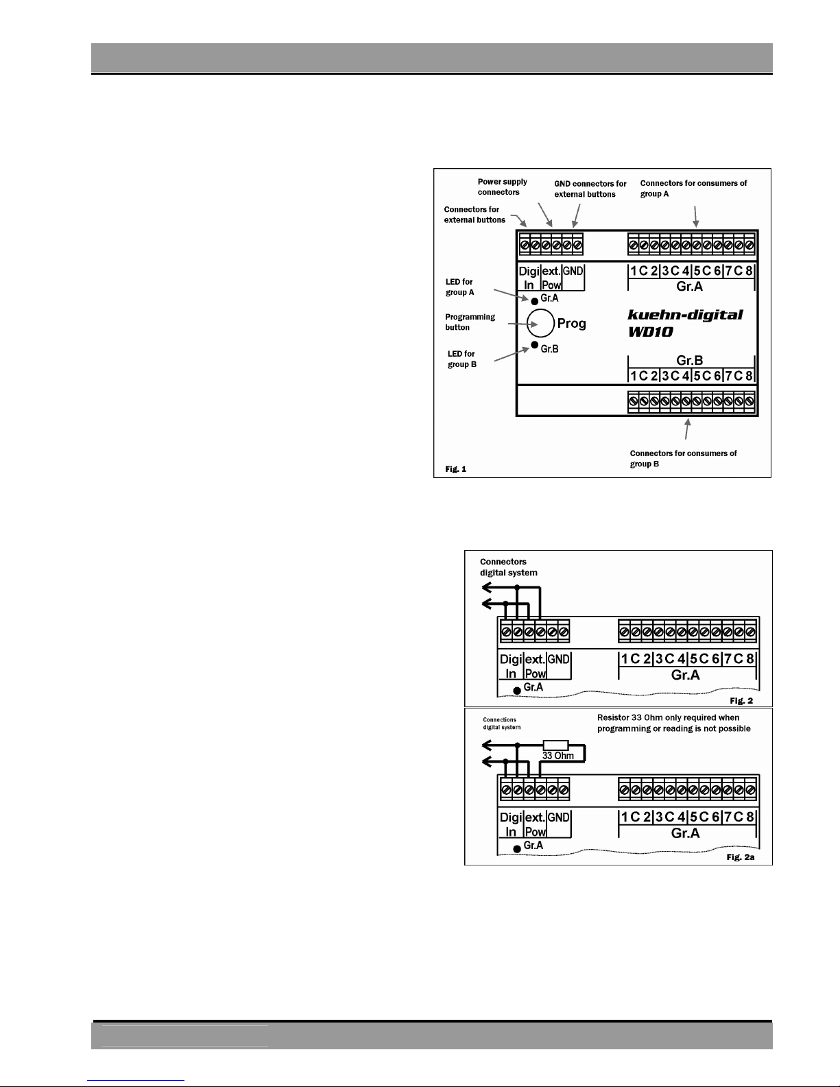
3.1. Connections and controls
The decoder has 16 switch outputs
divided in two groups (A and B) with 8
outputs each.
The connection points ext.Pow are
used to connect the power supply
(transformer connection).
The digital information is received by
the decoder over the Digi-In
connections. Should the points be
operated by local buttons then the
GND-connections come in use.
There is a sunken pushbutton in the
housing to set the decoder address.
The LEDs of the output groups are
showing the program step or the error
message of the switch decoder.
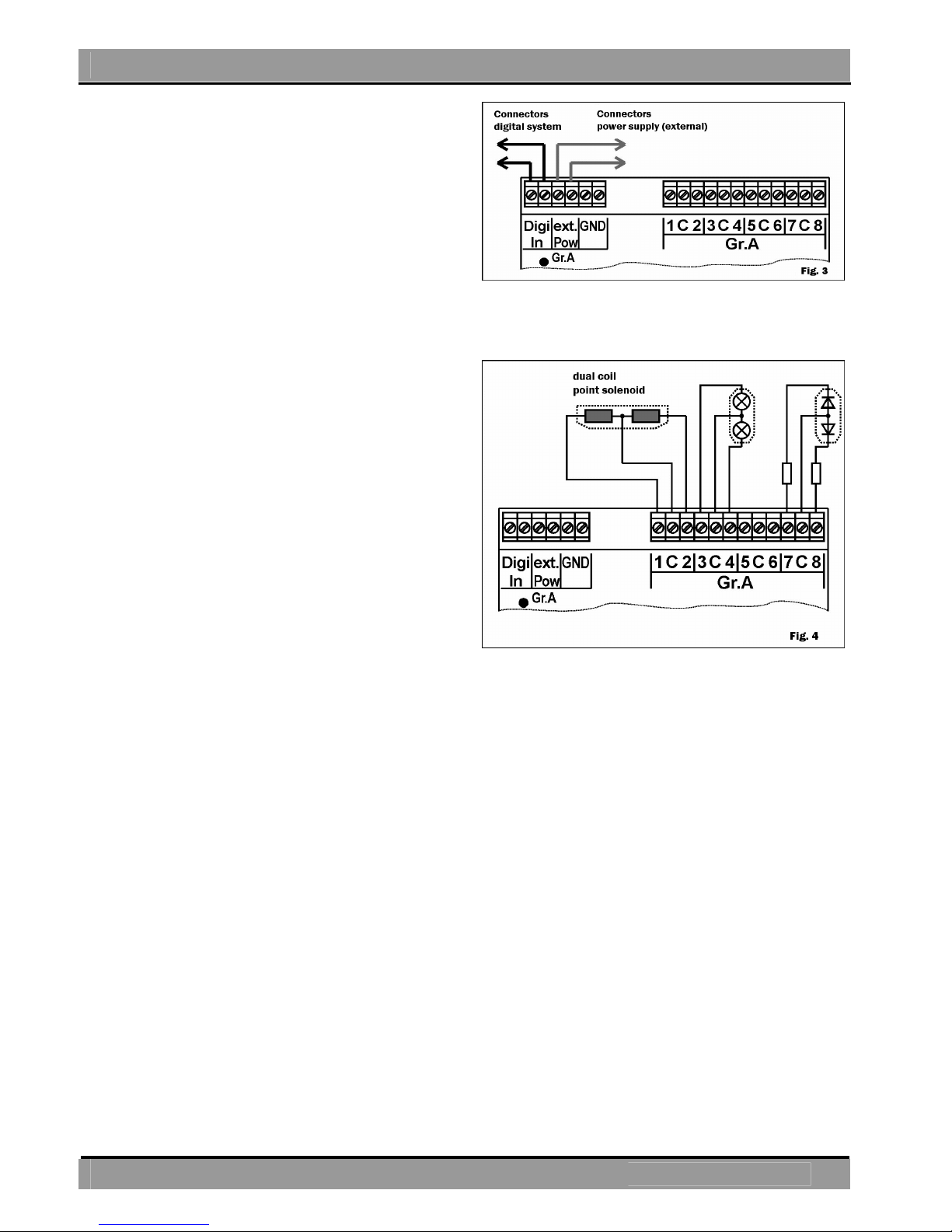
3.2.
Power from the digital controller
The easiest way to connect the power is
from the digital system. However
„expensive“ digital power is consumed in
this mode. Connect the connections
DIGI_IN with the connections ext.Pow
(external Power) according to figure 2.
This type of connection is definitely
required for programming on the program
track of your digital controller! Depending
on the controller, it may be necessary to
use a resistor 0f 33 Ohm in the power line
(See figure 2a).
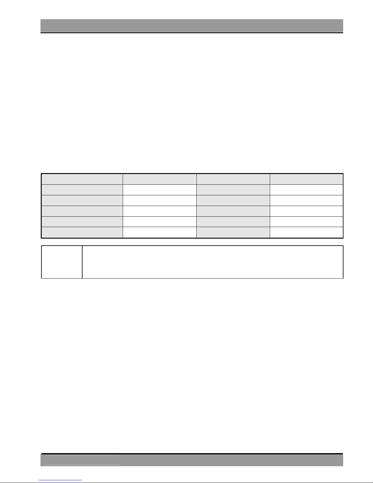
3.3. External power supply
By many consumers that need a lot of energy an external power supply for the
switch decoder is recommended. This prevents the use of „expensive” digital
current. Use only suitable power supplies (e.g. model railway transformers). The
decoder will receive the switch commands of the digital controller through the
Manual WD10
5
kuehn
connections DIGI_IN. The external
power supply is connected to the
connections ext.Pow .
Hint: Connecting the GND-connections
on the power is not allowed and can
cause damage of the WD10!
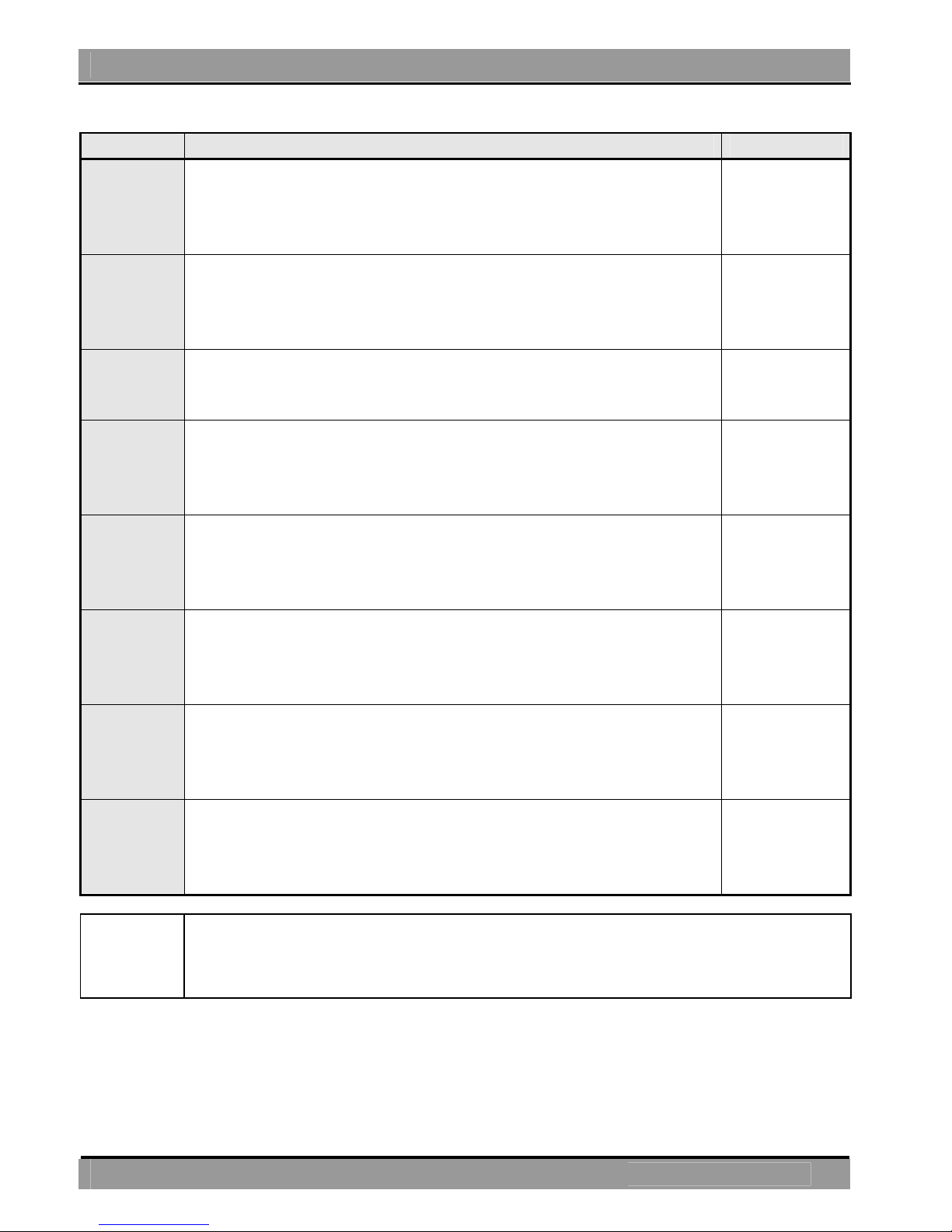
3.4. Connection of consumers
You can connect different consumers to
the switch decoder. Both the output
groups A and B behave identically.
Connecting dual solenoid points:
The common wire of the solenoid has
to be connected with C. The other two
wires of the solenoid are connected left
and right of C (see figure 4). Is the
position of the point not according to
the button pressed, exchange both
wires of the solenoid.
Connecting light signals with bulbs: The common wire of the light signal has to be
connected with C. The other two wires of the bulbs are connected left and right of
C (see figure 4).
Connecting light signals with LED: The common wire of the light signals has to be
connected with C. This connector has a positive potential, which means that the
anodes of the LED have to be connected to C. The LED should never be
connected directly. You need a series resistor! Check if your signal already has
one built-in.
Connecting point motors: Motorized points cannot be connected directly to the
decoder. Use either a toggle relays or an adapter for motorized points (MA10).
3.5. Switching of consumers
The control of the switch decoder is varies a lot from controller to controller,
please read the manual of your digital controller.
6
ManualWD10
kuehn
4. Decoder settings
4.1. General instructions of the settings
The switch decoder WD10 has two output groups with 4 connection pairs each (in
total 8 connections per group). Very often these output pairs are used for
switching points – one connection sets the point to straight the other connection
to branch. These connection pairs are addressed under their point numbers over
the digital controller. To set a connected point, the switch decoder must be set to
the number of the point. Each output group of the decoder includes 4 consecutive
point numbers. The number of this „group of four“ corresponds with the decoder
address. In the table below you will find an example of the assignment of point
numbers to a decoder address (CV#1 for group A and CV#35 for group B) for the
first 40 point numbers:
Point number
Decoder address
Point number
Decoder address
1,2,3 and 4
1
21,22,23 and 24
6
5,6,7 and 8
2
25,26,27 and 28
7
9,10,11 and 12
3
29,30,31 and 32
8
13,14,15 and 16
4
33,34,35 and 36
9
17,18,19 and 20
5
37,38,39 and 40
10
Hint
At the Multimaus (ROCO) and Lenz compact version 3.0 the point
numbers associated with the decoder address are always one down,
e.g. point 5 is associated with decoder address 1.
4.2. Operation modes of the switch decoder
The switch decoder WD10 can for the most used applications very easily be set by
the selection of operation modes.
If you want to make additional adjustments for your desired performance, set the
user-mode (mode 1). Thereby you will have full access to the many adjustments of
the WD10 through DCC programming. The setting of the operation mode is either
be done by the programming button (see next chapter) or by programming the
registers with your DCC controller.
On delivery the operation mode is set to 2. The outputs are driven in pairs (e.g.
switching points). Regardless the duration of the activation of the point button, the
output will shut down after 0,064 seconds, to protect the solenoid) (factory
settings). A renewed push on the button is only possible after 0,5 seconds.
Manual WD10
7
kuehn
Mode
Description
Similar to
1
(5)
*
User mode:
All settings can be done through the configuration
register, e.g. changing switch times, operate barriers
and barrier lights, etc.
-
2
(6)
*
4 output pairs on pulse output,
output remains active according the timer settings
(factory set 0,064 seconds) regardless the duration of
the pressing of the button
Lenz
LS100
(standard)
3
(7)
*
4 output pairs on pulse output,
output stays active as long as the button is pushed or
until the controller switches of automatically
Märklin®
K83
4
(8)
*
4 output pairs on continues operation,
available for, per example, two light signals without soft
light change or other continuous consumers (no layout
power switchable, therefore use an external relays)
Märklin®
K84 Other
wiring !
5
(9)
*
Light mode
depending on the command different light-effects are
made for construction sites or billboards (see chapter
6).
-
6
(10)
*
Light signals with two signal images (block signals)
You can connect 4 light signals with two signal images
per output group. The signal will prototypically light up
and dim.
-
7
(11)
*
Light signals with max. 4 signal images
You can connect 2 light signals with 4 signal images
per output group. The signal will prototypically light up
and dim.
8
(12)
*
NS-light signals with max 4 signal images
From „red“ to „green“ will be prototypically switched
over „yellow“. The lamps will prototypically light up and
dim.
*
)
Hint
For the Multimaus and Lenz compact version 3.0 use a 4 higher
switch number to set the mode with the programming button, e.g. for
mode 5 (light mode) switch point 9.
4.3. Set up by programming button
The switch decoder can be set to the most important applications very easily and
without extensive programming on the programming track, using the integrated
 Loading...