

Kuebler DS 417, Series 5888, Series 5868 Technical Manual
Technical Manual
Absolute Multiturn
Encoders
Fieldbus
PPrrooffiillee ffoorr
LLiifftt aapppplliiccaattiioonns
s
Series 5868
Series 5888
Technical Manual
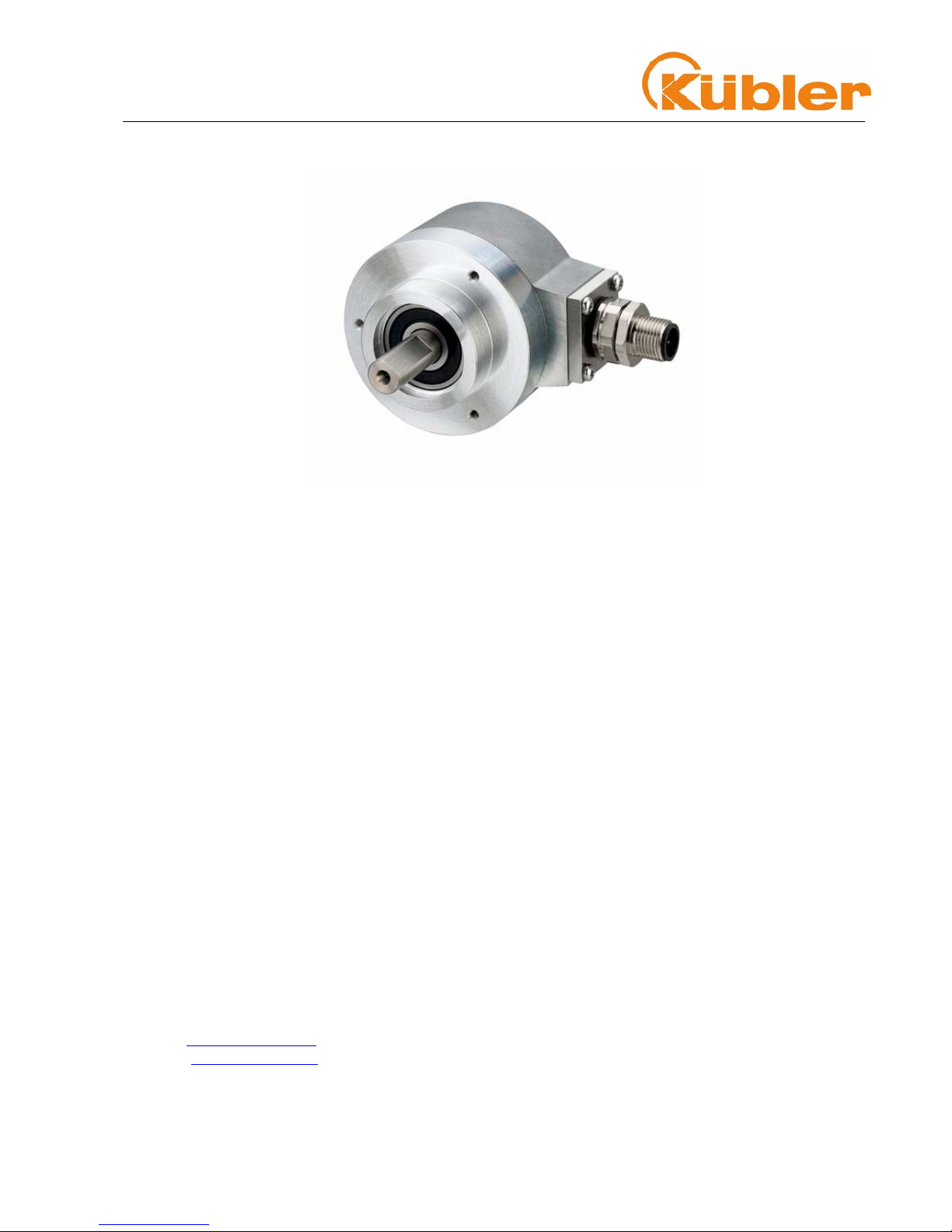
Absolute Multiturn Encoders
CCAANNLLiifft
t
R.000.000 1-2 of 41
©© FFrriittzz KKüübblleerr GGmmbbHH
Copyright Protection
The contents of this documentation are protected by copyright © Fritz Kübler GmbH. The contents of
this documentation may not be altered, expanded, reproduced nor circulated to third parties, without the
prior written agreement of Fritz Kübler GmbH.
Liability to modification without notice
As a result of ongoing efforts to improve our products, we reserve the right to make changes at any time
to technical information contained in the document to hand.
Warranty Disclaimer
Fritz Kübler GmbH provides no guarantee, neither tacit nor express, in respect of the whole manual
(whether this applies to the original German text or to the English translation) and assumes no liability for
any damage, neither direct nor indirect, however caused.
Document information
Revised 04-2006
Screen printouts used
CANalyzer
®
Fa. Vector–Informatik
CANWizard
®
Fa. Böhnke & Partner
Fritz Kübler GmbH Schubertstr.47
78054 VS-Schwenningen / Germany
Tel. +49 (0) 7720-3903-0
Fax +49 (0) 7720-21564
E-Mail: info@kuebler.com
Internet: www.kuebler.com

Technical Manual
Absolute Multiturn Encoders
CCAANNLLiifft
t
R.000.000 1-3 of 41
Table of Contents:
1
GENERAL......................................................................................1-5
CANLIFT MULTITURN ENCODER SERIES 5868/88.....................................................................................................1-5
THE CANOPEN PROFILE...........................................................................................................................................1-5
2 CANLIFT ENCODER DEVICE PROFILE DS 417 V1.1 ...............2-6
DATA TRANSMISSION ................................................................................................................................................2-6
TRANSMISSION OF PROCESS DATA ...........................................................................................................................2-6
3 CONFIGURATION USING THE CANWIZARD® ..........................3-7
4 INITIAL STARTUP - GENERAL DEVICE SETTINGS ................4-8
BAUD RATE ..............................................................................................................................................................4-8
CANBUS TERMINATION ............................................................................................................................................4-8
NODE NUMBER .........................................................................................................................................................4-9
5 CANBUS CONNECTION...............................................................5-9
D-SUB 9 CONNECTOR PIN ASSIGNMENT.....................................................................................................................5-9
M23 CONNECTOR PIN ASSIGNMENT + CABLE CONNECTION.........................................................................................5-9
M12 CONNECTOR PIN ASSIGNMENT ...........................................................................................................................5-9
6 DEFAULT SETTINGS ON DELIVERY........................................6-10
COMMUNICATION PARAMETERS .............................................................................................................................. 6-10
CANLIFT ENCODER PROFILE................................................................................................................................. 6-11
7 EXTERNAL PRESET ..................................................................7-12
8 DEFINITION OF THE TRANSMISSION TYPE OF THE PDO ...8-13
VARIABLE PDO MAPPING ...................................................................................................................................... 8-13
9 DEFAULT TRANSMIT PDO1 MAPPING ....................................9-14
TWO VIRTUAL DEVICES.......................................................................................................................................... 9-14
10 APPLICATION PROGRAMMING EXAMPLE:..........................10-15
SETTING THE PARAMETERS WITH THE CANWIZARD............................................................................................... 10-15
SAVE ALL CHANGED PARAMETERS IN THE EEPROM STORE PARAMETERS 1010H................................................. 10-16
Object 1010h Store Parameters.................................................................................................................. 10-16
Object 1011h: Load Standard Values......................................................................................................... 10-16
11 OBJECT 1018H: IDENTITY OBJECT.......................................11-17
12 CONFIGURATION OF THE SPEED OUTPUT .........................12-18
OBJECT 6384H: ENCODER MEASURING STEP VALUES FOR THE SPEED CALCULATION ........................................... 12-18
13 EMERGENCY OBJECTS..........................................................13-19
FORMAT OF AN EMERGENCY MESSAGE ................................................................................................................ 13-20
EMERGENCY OBJECT PROTOCOL......................................................................................................................... 13-20
14 CANOPEN OBJECT DICTIONARY ..........................................14-21
STRUCTURE OF THE ENTIRE OBJECT DICTIONARY:................................................................................................ 14-21
15 THE COMMUNICATION PROFILE CANOPEN PROFILE DS 301 V4.1 15-22
COMMUNICATION OBJECTS .................................................................................................................................. 15-22
MANUFACTURER-SPECIFIC OBJECTS.................................................................................................................... 15-22
16 CANLIFT DEVICE PROFILE DS 417 V1.1 ..............................16-23

Technical Manual
Absolute Multiturn Encoders
CCAANNLLiifft
t
R.000.000 1-4 of 41
CAR POSITION UNIT............................................................................................................................................ 16-23
OBJECT 6000H: SUPPORTED VIRTUAL DEVICE TYPES............................................................................................ 16-24
OBJECT 6001H: LIFTNUMBER .............................................................................................................................. 16-24
OBJECT 6380H OPERATING PARAMETERS ........................................................................................................... 16-24
OBJECT 6381H: MEASURING UNITS PER REVOLUTION (RESOLUTION) ................................................................... 16-25
OBJECT 6382H: PRESET VALUE .......................................................................................................................... 16-25
OBJECT 6383H: POSITION VALUE ........................................................................................................................ 16-26
OBJECT 6390H: SPEED VALUE ............................................................................................................................ 16-26
OBJECT 6391H: ACCELERATION VALUE............................................................................................................... 16-26
OBJEKT 63B0H: WORKING AREA STATE REGISTER 2 VALUES POSITION UNIT 1................................................... 16-27
OBJECT 63B4H: WORKING AREA LOW LIMIT 2 VALUES....................................................................................... 16-27
OBJECT 62B8H: WORKING AREA HIGH LIMIT 2 VALUES ...................................................................................... 16-27
OBJECT 63C0H: DISPLAY OPERATING STATUS .................................................................................................... 16-28
OBJECT 63C1H: SINGLETURN RESOLUTION.......................................................................................................... 16-28
OBJECT 63C2H: NUMBER OF REVOLUTIONS ........................................................................................................ 16-28
OBJECT 63C4H: SUPPORTED WARNINGS............................................................................................................. 16-28
OBJECT 63C5H: WARNINGS ................................................................................................................................ 16-29
OBJECT 63C6H: SUPPORTED ALARMS................................................................................................................. 16-29
OBJECT 63C7H: ALARMS.................................................................................................................................... 16-30
OBJECT 2100H: BAUD RATE ................................................................................................................................ 16-30
OBJECT 2101H: NODE ADDRESS.......................................................................................................................... 16-31
OBJECT 2102H: CANBUS TERMINATION .............................................................................................................. 16-31
OBJECT 2103H: FIRMWARE FLASHVERSION ......................................................................................................... 16-31
OBJECT 2130H: ENCODER MEASURING STEP ...................................................................................................... 16-32
OBJECT 1029H ERROR BEHAVIOUR..................................................................................................................... 16-32
OBJECTS NOT MENTIONED................................................................................................................................... 16-32
17 NETWORK MANAGEMENT .....................................................17-33
NMT COMMANDS ................................................................................................................................................ 17-34
18 HEARTBEAT PROTOCOL........................................................18-34
19 LED MONITORING DURING OPERATION..............................19-35
LED COMBINATIONS DURING OPERATION.............................................................................................................. 19-36
20 GENERAL RESET - SWITCHING THE DEVICE ON WITH THE SET-KEY PRESSED 20-36
21 DEFINITIONS.............................................................................21-37
ABBREVIATIONS USED ......................................................................................................................................... 21-37
22 DECIMAL-HEXADECIMAL CONVERSION TABLE.................22-38
23 GLOSSARY ...............................................................................23-39
24 INDEX ........................................................................................24-40
25 TECHNICAL DATA ELECTRICAL, MECHANICAL ................25-41

Technical Manual
Absolute Multiturn Encoders
CCAANNLLiifft
t
R.000.000 1-5 of 41
11 GGeenneerraall
CANLift Multiturn Encoder Series 5868/88
The CANLift encoders of Series 5868/88 support the latest CANopen communication
profile according to DS 301 V4.02 . In addition the device-specific profile DS 417 V1.1
has been adapted (for lift applications).
The following operating modes can be selected: Polled Mode, Cyclic Mode, Sync Mode and a High
Resolution Sync Protocol. Moreover, scale factors, preset values, limit switch values and many other
additional parameters can be programmed via the CAN-Bus. At Power ON all parameters are loaded
from an EEPROM, which had previously been saved in the non-volatile memory to protect them in case
of power failure. The following output values may be freely combined as PDO (PDO Mapping):
position, speed, acceleration as well as the status of the four limit switches.
Moreover the encoders are available with D-SUB, M12 or M23 connectors, or with a cable connection,
for which changes to the device address and baud rate are software controlled.
Three LEDs located on the back indicate the operating or fault status of the CAN bus, as well as the
status of an internal diagnostic.
CANLift encoders are available in blind hollow shaft and solid shaft versions, and are ideal for use in
harsh industrial environments thanks to their IP 65 protection rating.
The CANopen Profile
CANopen represents a unified user interface and thus allows for a simplified system structure with a
wide variety of devices. CANopen is optimized for the fast exchange of data in real-time systems and
possesses a number of different device profile that have been standardized. The CAN in Automation
(CiA) manufacturers and users group is responsible for creating and standardization of the relevant
profiles.
CANopen offers
• user-friendly access to all device parameters.
• auto-configuration of the network and of the devices
• device synchronization within the network
• cyclic and event-driven process data exchange
• simultaneous read and write of data
CANopen uses four communication objects (COB) with different properties
• Process Data Objects (PDO) for real-time data,
• Service Data Objects (SDO) for transmitting parameters and programs,
• Network Management (NMT, Life-Guarding, Heartbeat)
• Predefined Objects (for Synchronisation, Time-Stamp, Emergency)
All device parameters are filed in an Object Dictionary. This Object Dictionary contains the description,
data type and structure of the parameters, as well as the address (Index).
The dictionary is divided into a communications profile section, a section covering the device profile as
well as a section specific to the manufacturer.

Technical Manual
Absolute Multiturn Encoders
CCAANNLLiifft
t
R.000.000 2-6 of 41
22 CCAANNLLiifftt EEnnccooddeerr DDeevviiccee PPrrooffiillee DDSS 441177 VV11..11
The CANLift encoder is designed specially to fulfil the requirements of the Lift Industry
and meets the CiA specifications acc. to DSP417. The encoder is already pre-configured
with many parameters, so offering the customer a simple plug and play option. Any
necessary changes or settings for a particular application can be carried out quickly and
easily via EDS files, using a configuration tool such as CANWizard from BÖHNKE +
PARTNER® .
Firstly the encoder will be assigned a lift shaft by means of the parameter Lift Number.
The objects for the device parameters will hereupon be automatically adjusted to suit. Up
to 3 PDO channels are available for the communications, all of which have already been
configured to the position Unit 1.
Data transmission
With CANopen data are transferred via two different communication types (COB=Communication
Object) with different properties:
• Process Data Objects (PDO – real-time capable)
• Service Data Objects (SDO)
The Process Data Objects (PDO) provide high-speed exchange of real-time data (e.g.
encoder position, speed, comparative position status) with a maximum length of 8 byte. These data are
transmitted with a high priority (low COB-Identifier). PDOs are broadcast messages and provide their
real-time data simultaneously to all desired receivers. PDOs can be mapped, i.e. 4 byte of position and 2
byte of speed can be combined in one 8 byte data word.
The Service Data Objects (SDO) form the communication channel for the transfer of device parameters
(e.g. programming the resolution of the encoder). As these parameters are transmitted acyclically (e.g.
only once during boot-up of the network), the SDO objects have a low priority (high COB-Identifier).
Transmission of Process Data
With the CANLift encoder three PDO services PDO1 (tx) ,PDO2 (tx) and PDO3(tx) and a ReceivePDO are available. A PDO transmission can be triggered by a variety of events (see Object Dictionary
Index 1800h):
• asynchronously (event driven) by an internal cyclic device timer or by a change in the process
value of the sensor data
• synchronously as a response to a SYNC telegram; (a SYNC command will cause all CANopen
nodes to store their values synchronously, after which they are transferred in succession to the
bus according to their set priority)
• as a response to an RTR-Telegram (per Remote Frame=recessive RTR-bit, exactly that
message with the communicated ID will be requested)
Technical Manual
Absolute Multiturn Encoders
CCAANNLLiifft
t
R.000.000 3-7 of 41
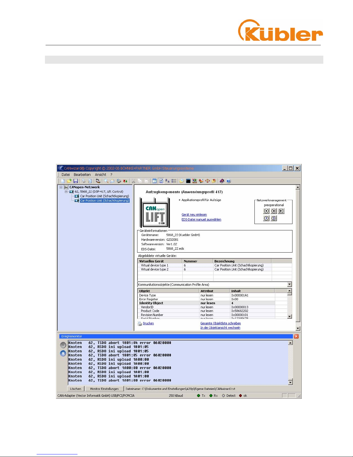
33 CCoonnffiigguurraattiioonn uussiinngg tthhee CCAANNWWiizzaarrdd®®
The CANWizard has a wide variety of features, specially for use with lifts, and which comply with the CiA
DSP-417 application profile. The Software is part and parcel of the control concept that is designed and
manufactured by the company BÖHNKE + PARTNER® GmbH.
In the upper area the Device Name, the CANopen Profile and the operating elements for the network
management are displayed. There are also two links, either for reading in the device again or for
manually assigning a particular EDS file to this device.
Below this are displayed the device information for this node and the name of the assigned EDS file.
In the lower part of the window are the selection fields for the parameter assignment of the device.
These are dependent on the particular device.
The encoder possesses two virtual devices, which can be configured independently of each other.
Technical Manual
Absolute Multiturn Encoders
CCAANNLLiifft
t
R.000.000 4-8 of 41
44 IInniittiiaall SSttaarrttuupp -- GGeenneerraall DDeevviiccee SSeettttiinnggss
Baud rate
The default setting on delivery is 125 kbit/s. The baud rate can however be changed from 0..9 by
reprogramming in Object 2100h from 0..9. The following baud rates are available to the user:
² Factory default setting
Please note the following when selecting a baud rate
The chosen cycle time (see Object 1906h,Sub-index 5 Event Timer) must be longer than
the bus transfer time, to ensure that the PDOs are communicated error-free!
With a baud rate of 10 KBaud: cycle time must be at least 14 ms
With a baud rate of 20 KBaud: cycle time must be at least 10 ms
With a baud rate of 50 KBaud: cycle time must be at least 4 ms
With a cycle time=0 in Event-Mode (i.e. PDO on value change) the baud rate must be at least 125
KBaud.
CANbus Termination
The bus termination can be switched on using the software via Object 2102h. By default the value is set
to 1, which means that the bus termination of the device is switched on.
Range of values 0..1
Default setting: 1
The CANbus must be terminated at both ends between CAN_H and CAN_L using 120 Ohm bus
termination resistors.
Value Baud rate in
kbit/s
0
10
1
20
2
50
3
100
4
125²
5
250
6
500
7
800
8
1000
9
Autobaud
Technical Manual
Absolute Multiturn Encoders
CCAANNLLiifft
t
R.000.000 5-9 of 41
Node number
It is possible to change the node number by reprogramming in Object 2101h. If the value in Object
2101h is set to FFh, then the node number will be read from the internal switches. (Switches are set to
the node number default value 10h)
Default setting
10h corresponds to 16 decimal
Node number 0 is reserved and must not be used by any node.
The resulting node numbers lie in the range 1...7Fh hexadecimal (1...127 decimal).
Please note !
No logical connection exists between the node number and the COB-ID of the transmit parameters,
i.e. the IDs for TPDO1+2 have fixed values assigned to them.
The acceptance of a new node number only becomes effective when the encoder is rebooted
(Reset/Power-on) or by means of an NMT Reset Node command. All other settings within the
object table are however retained.
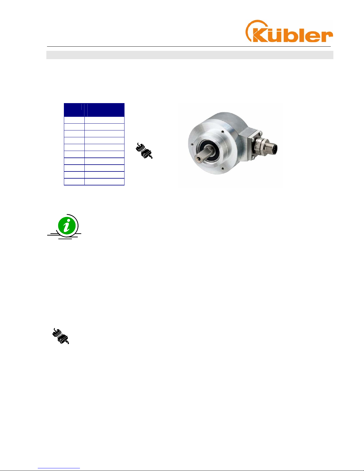
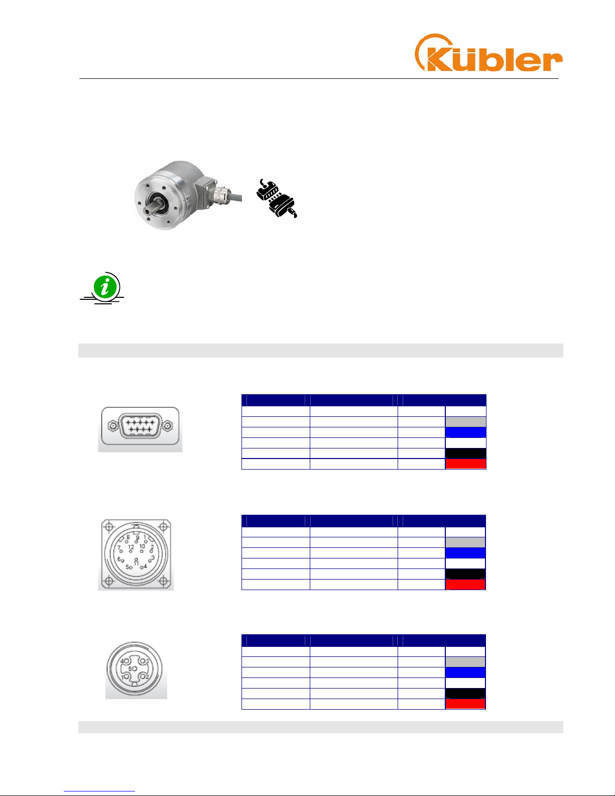
55 CCAANNbbuuss ccoonnnneeccttiioonn
D-Sub 9 Connector pin assignment
Connection diagram D-SUB pin assignment
M23 Connector pin assignment + cable connection
Connection diagram M23 connector and cable connection
M12 Connector pin assignment
Connection diagram M12 connector
Abbreviation Description PIN No. Colour
CG CAN Ground 3
CL CAN_Low (-) 2
CH CAN_High (+) 7
0V 0 Volt Supply 6
+V +UB Supply 9
Abbreviation Description PIN No. Colour
CG CAN Ground 3
CL CAN_Low (-) 2
CH CAN_High (+) 7
0V 0 Volt Supply 10
+V +UB Supply 12
Abbreviation Description PIN No. Colour
CG CAN Ground 3
CL CAN_Low (-) 5
CH CAN_High (+) 4
0V 0 Volt Supply 1
+V +UB Supply 2

Technical Manual
Absolute Multiturn Encoders
CCAANNLLiifft
t
R.000.000 6-10 of 41
66 DDeeffaauulltt sseettttiinnggss oonn ddeelliivveerryy
On delivery the following software parameters have been factory set.
Description Setting Switch Software
Baud rate 125 kBit/s
Switch setting 5 Object 2100h = 04h
Node address 16
Switch setting 10h Object 2101h = 10h
Termination ON
Switch setting off Object 2102h = 01h
Index (hex) Name Standard value
Communication parameters
1000h
Device Type 00 (Multiple Virtual Device)
1005h
COB-ID Sync 80h
100Ch
Guard Time 0
100Dh
Life Time Factor 0
1012h
COB-ID Time stamp 100h
1013h
High Resolution time stamp 0
1017h
Producer heartbeat time
2500 ms
1029h
Error Behaviour 0 = Comm Error
1 = Device specific
1 = Manufacturer Err.
1906h TPDO1 Communication Parameter
01h
COB-ID
18Ch
02h
Transmission Type 255 (asynch)
03h
Inhibit Time 0
05h
Event counter 20ms
1907h TPDO2 Communication Parameter
01h
COB-ID
18Dh
02h
Transmission Type 255 (asynch)
03h
Inhibit Time 0
05h
Event counter 20ms
1B06h TPDO1 Mapping
01h
1.Mapped Object
0x63830120
02h
2.Mapped Object 0x63900110
03h
3.Mapped Object 0x63B00108
1B07h TPDO2 Mapping
01h
1.Mapped Object
0x63830220
02h
2.Mapped Object 0x63910110

Technical Manual
Absolute Multiturn Encoders
CCAANNLLiifft
t
R.000.000 6-11 of 41
Index (hex) Name Standard value
CANLift Encoder Profile
6000h
Supported Virtual Device types
06
6001h
Lift number
1
6380h
Operating Parameter
0x04h Scaling on
6381h
Measuring Units per Revolution
8192 (13 Bit)
6382h
Preset value 0
6384H
Encoder Measuring Step
Position Measuring Step
1
Speed Measuring Step
10
Acceleration Measuring Step
1
63B1h
Work area low limit 0
63B2h
Work area high limit 33554400
63C2h
Number of Revolutions
4096
2100h
Baud rate
04h
2101h
Node number
10h
2102h
CANbus terminination
0 (not active)
The original Standard Values (default values on delivery) can be reloaded again by means
of Object 1011h (restore parameters).
In order to ensure that parameter changes are saved in the event of power failure, then these must
without fail be transferred to the EEPROM by means of Object 1010h (store parameters). This will cause
all data already present in the EPROM to be over-written!
If errors have occurred during programming of the objects and if these parameters are
then saved in the EEPROM, it will not be possible to address the encoder next time it is
switched on (the encoder will send only Emergency messages).
This error can be cleared only by means of a general Reset of the encoder.
Please note that all programmed parameters will be lost.
• Switch the encoder off
• Turn the encoder back on, keeping the Set-key* pressed for
ca. 3 seconds until the DIAG LED flashes
• Switch the device off again.
When the encoder is rebooted all values will be reset to their default settings, in exactly the same way
as sending Object 1011h Restore Parameters.
Technical Manual
Absolute Multiturn Encoders
CCAANNLLiifft
t
R.000.000 7-12 of 41
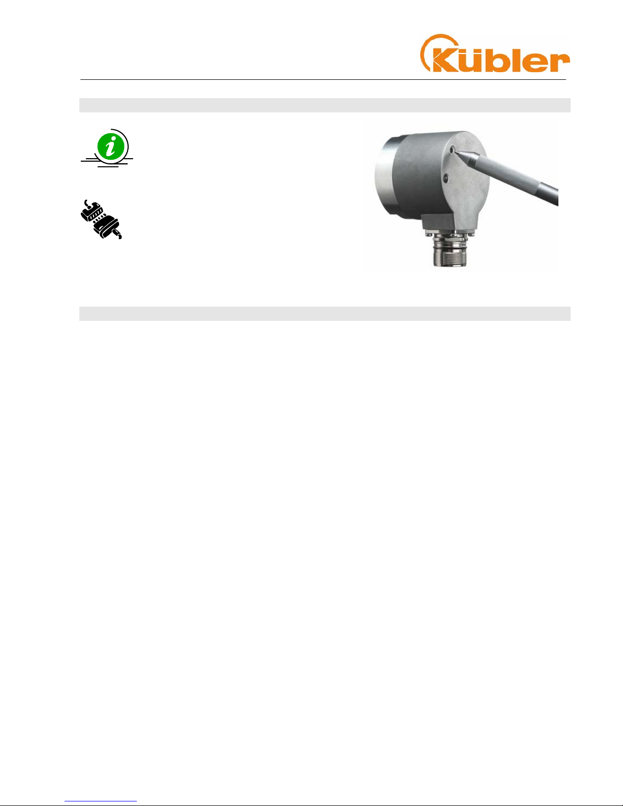
77 EExxtteerrnnaall PPrreesseett
The device can be set to the preset value
by means of the built-in SET key.
The resulting position is dependent on the
value programmed in Object 6382h.
Default setting: 0
as per illustration
Technical Manual
Absolute Multiturn Encoders
CCAANNLLiifft
t
R.000.000 8-13 of 41
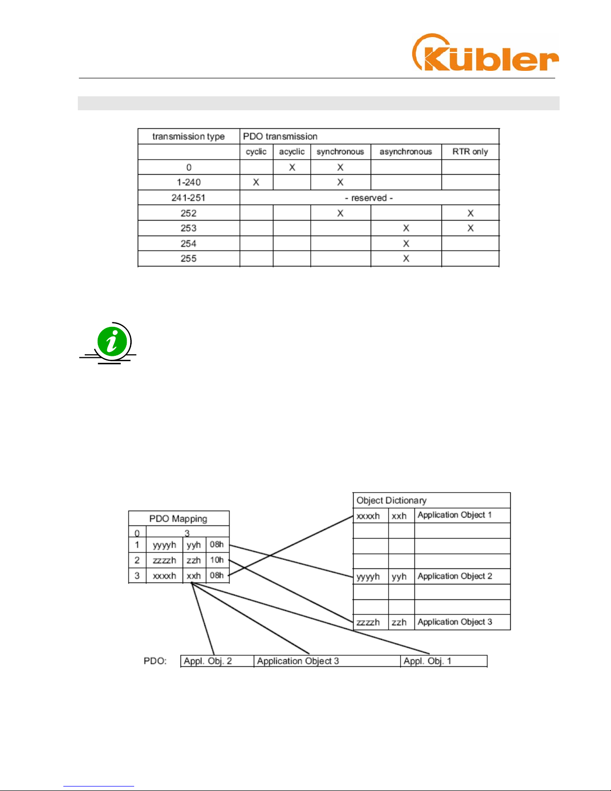
88 DDeeffiinniittiioonn ooff tthhee ttrraannssmmiissssiioonn ttyyppee ooff tthhee PPDDOO
A value between 1 ...240 means that the PDO will be sent synchronously and cyclically. The number of the
Transmission Type signifies the quantity of SYNC pulses that are necessary to forward the PDOs.
The Transmission Types 252 and 253 state that the PDO will only be sent when requested via an RTR.
Type 254 means that the event will be triggered depending on the application (application-specific),
whereas Type 255 is dependent on the device (device-specific). Additionally for Numbers 254/255
a time-controlled EventTimer can be used. The values for the timer can range from 1ms ... 65535
ms.
Variable PDO Mapping
Variable Mapping of the various objects means that the user is able to configure the content of the
Transmit PDOs dependent on the application.
Example of an entry in the Mapping Table:
The mapped PDO consists of 3 Application Object entries of varying lengths:
Application Object 2 occupies Byte 1 (08h) in the Transmit PDO. Thereafter follows Application Object 3
with a length of 16 bit (10h = 2 bytes) and finally Application Object 1 with a length of 1 byte. In total, 32
bits are occupied in this PDO.
Technical Manual
Absolute Multiturn Encoders
CCAANNLLiifft
t
R.000.000 9-14 of 41
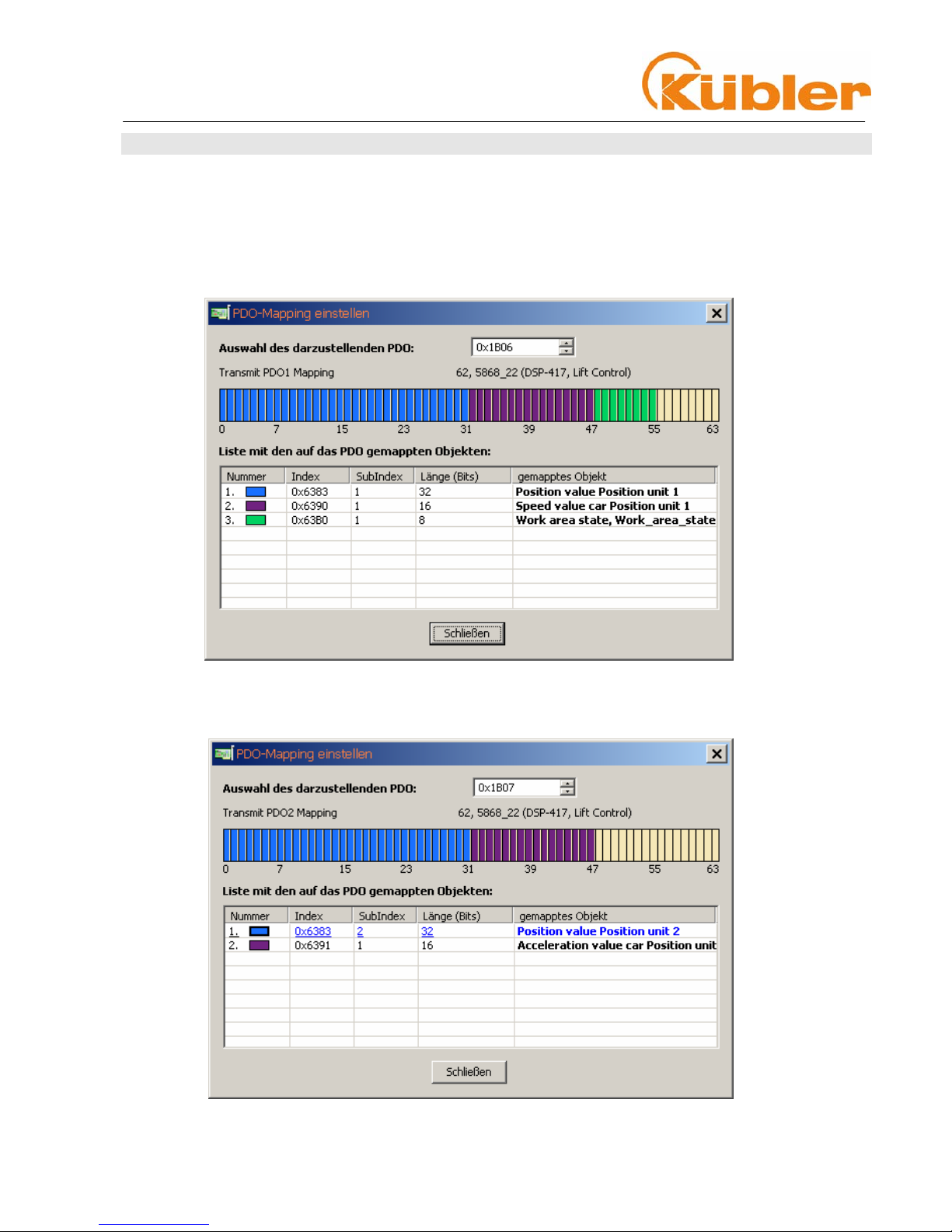
99 DDeeffaauulltt TTrraannssmmiitt PPDDOO11 MMaappppiinngg
Two Virtual Devices
The Mapping Object for Transmit PDO 1 and PDO2 is defined in the Object Dictionary Indexes 1B06h
and 1B07h. It consists of 2 entries and can be modified by the user (variable mapping). A pre-defined
mapping exists for the first virtual device.
TPDO1 Mapping Object 1B06h has the following assignment:
A pre-defined mapping exists for the second virtual device.
TPDO2 Mapping Object 1B07h has the following assignment:
Technical Manual
Absolute Multiturn Encoders
CCAANNLLiifft
t
R.000.000 10-15 of 41
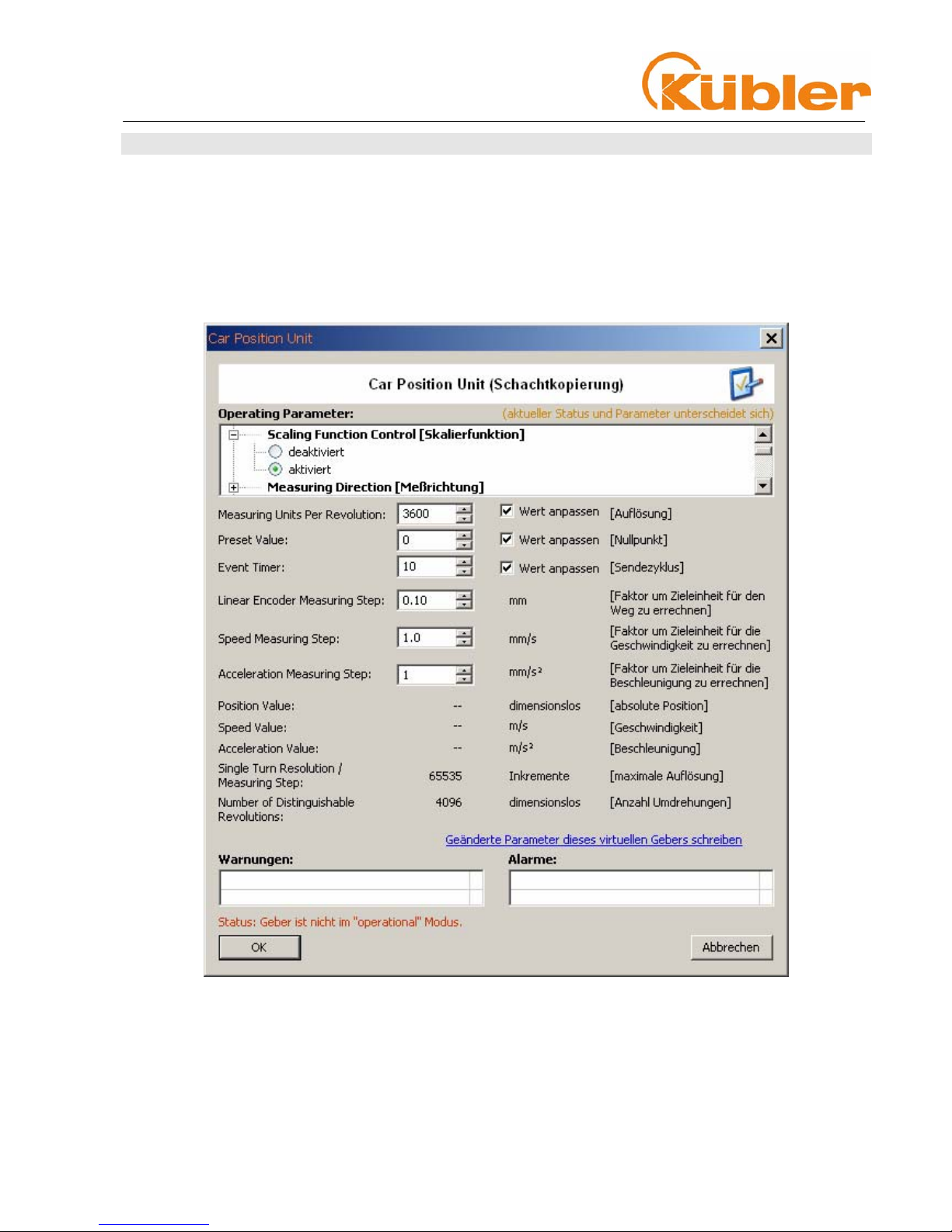
1100 AApppplliiccaattiioonn PPrrooggrraammmmiinngg EExxaammppllee::
Requirements:
• Resolution per revolution should be set to 3600 steps per revolution
• Position Value should be set to 0
• TPDO1 (Position) should transmit the event every 10 ms
• The new parameters should be saved in the EEPROM
Setting the parameters with the CANwizard
Additionally a time-controlled EventTimer can be used for the Transmit PDOs. The values for the
timer can range from 1 ms ... 65535 ms.
Technical Manual
Absolute Multiturn Encoders
CCAANNLLiifft
t
R.000.000 10-16 of 41
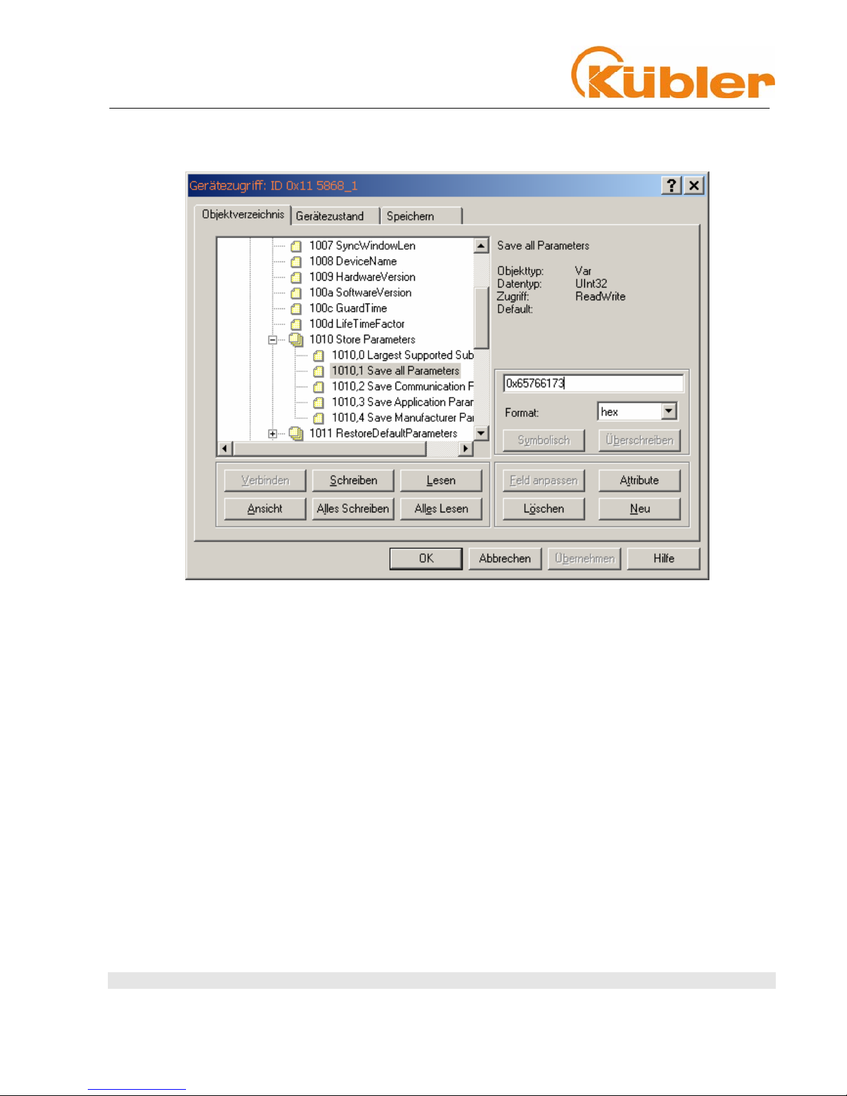
Save all changed parameters in the EEPROM
Store Parameters 1010h
OObbjjeecctt 11001100hh SSttoorree PPaarraammeetteerrss
Using the command "save" under Sub-Index 1h (Save all Parameters) causes all the parameters to be
stored in the non-volatile memory (EEPROM).
All Communication Objects, Application Objects and Manufacturer-specific Objects are saved under this
Sub-Index. This process requires ca. 14 ms.
In order to prevent an inadvertent save, the instruction will only be executed if the string "save" is
entered as a codeword into this Sub-Index.
A read access to the Sub-Index 1h provides information about the functionality of the memory.
Byte 0: 73h (ASCII-Code for "s")
Byte 1: 61h (ASCII-Code for "a")
Byte 2: 76h (ASCII-Code for "v")
Byte 3: 65h (ASCII-Code for "e")
OObbjjeecctt 110
0
1111hh:: LLooaadd SSttaannddaarrdd VVaalluueess
Using the command "load" under Sub-Index 1h causes all parameters to be reset to their standard
values. In order to prevent inadvertent loading of the standard values, the instruction will only be
executed if the string "load" is entered as a codeword into this Sub-Index.
Technical Manual
Absolute Multiturn Encoders
CCAANNLLiifft
t
R.000.000 11-17 of 41
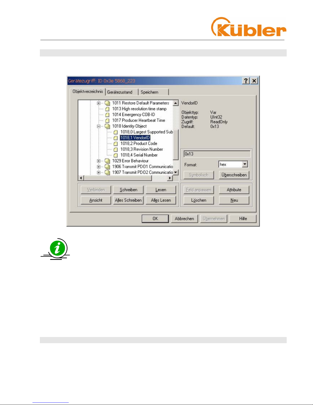
1111 OObbjjeecctt 11001188hh:: IIddeennttiittyy OObbjjeecctt
Information concerning the vendor and the device:
1018 RECORD Device – Identification read only
Sub-Index 0h : Number of Sub-indices“
supplies the value 4
Sub-Index 1h: "read" only
supplies the Vendor-ID (000000013h) Fritz Kübler GmbH
Sub-Index 2h: supplies the Product Code
(e.g. 0x58682001 CANopen encoder)
Sub-Index 3h: "read" only
supplies the Software revision Number
(e.g. 102)
Sub-Index 4h: "read" only
supplies the 8-digit Serial Number of the encoder
 Loading...