

Kucht K6502D User Manual

www.kucht.com
BE A PRO IN YOUR KITCHEN
K6502D - DISHWASHER
K430D - 166 Bottles
6
46db
WAS H
24”
BUIT-IN
DISHWASHER
INSTALLATION MANUAL
APPLICABLE MODEL: K6502D
Installation
Instructions
Dishwasher
FOR MORE DETAILS AND INFORMATION, PLEASE VISIT OUR WEBSITE
BEFORE YOU BEGIN
Read these instructions completely and
carefully.
IMPORTANT
governing codes and ordinances.
• Note to Installer – Be sure to leave these instructions
for the consumer’s and local inspector’s use.
• Note to Consumer – Keep these instructions with your
Owner’s Manual for future reference.
• Skill Level – Installation of this dishwasher requires
basic mechanical and electrical skills. Proper
installation is the responsibility of the installer.
Product failure due to improper installation is not
covered under the GE Appliance Warranty.
• Completion Time – 1 to 3 Hours. New installations
require more time than replacement installations.
Observe all
–
IMPORTANT –
MUST be installed to allow for future removal from
the enclosure if service is required.
If you received a damaged dishwasher, you should
immediately contact your dealer or builder.
FOR YOUR SAFETY
Read and observe all CAUTIONS and WARNINGS
shown throughout these instructions. While performing
installations described in this booklet, gloves, safety
glasses or goggles should be worn.
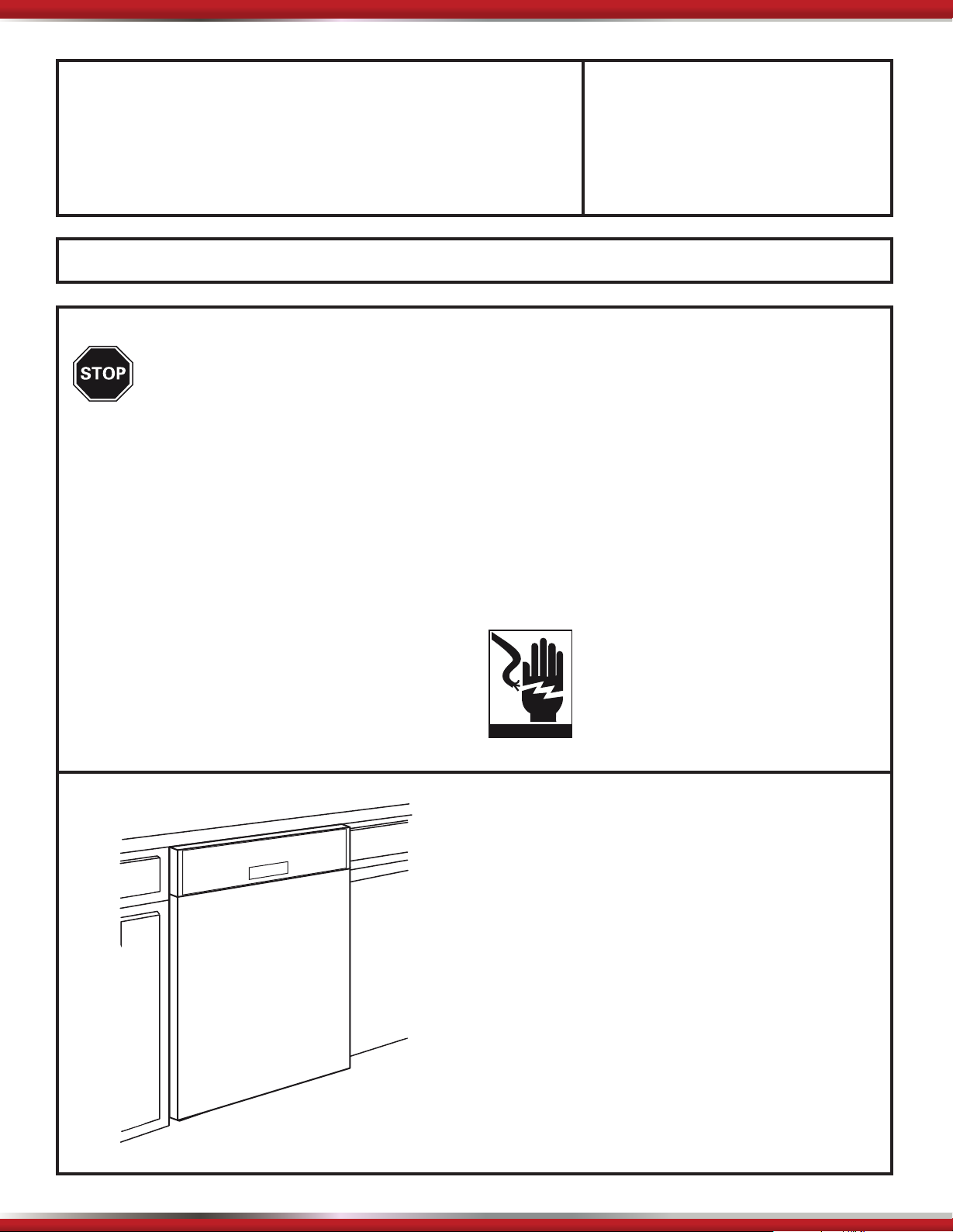
WARNING
To reduce the risk of electrical shock, fire,
or injury to persons, the installer must
ensure that the dishwasher is completely
enclosed at the time of installation.
WWW.KUCHT.COM
The dishwasher
READ CAREFULLY.
KEEP THESE INSTRUCTIONS.
If you have an installation problem, contact your
dealer or installer. You are responsible for providing
adequate electrical, exhaustingand other connecting
facilities.
Installation Preparation
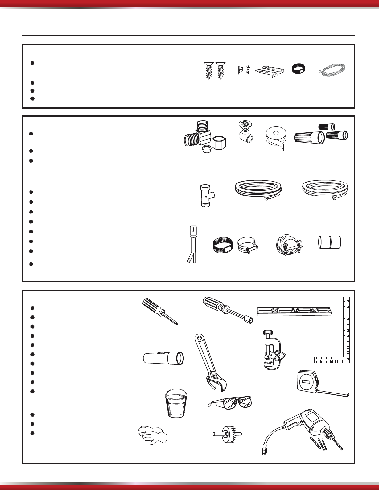
PARTS SUPPLIED:
Four flat head wood screws
dishwasher to underside of countertop
(in literature package).
Screw type hose clamps and one drain hose.
2 top mounting cl\ips.
MATERIALS YOU WILL NEED :
Ferrule, compression nut and 90° Elbow (3/8"NPT external
thread on one end, opposite end sized to fi t water supply)
Thread seal tape
UL Listed wire nuts (3)
Materials For New Installations Only:
Air gap for drain hose, if required
Waste tee for house plumbing, if applicable
Electrical cable or power cord, if applicable
Screw type hose clamps
Strain relief for electrical connection.
Hand shut-off valve
Water line 3/8" min. copper
Coupler for extending drain line, if applicable
to secure
.spilc gnitnuom edis 2@
4 Wood Screws
90° Elbow,
Ferrule and
Compression Nut
Waste Tee
Air Gap
2 Side
Mounting Clips
Hand
Shut-Off
Valve
Electrical Cable
(or Power Cord, if applicable)
Screw Type
Hose Clamps
2 Top
Mounting Clips
Thread
Seal Tape
Strain Relief
Screw Type
Hose Clamp
Wire Nuts (3)
Hot Water line
Drain Hose
Coupler
TOOLS YOU WILL NEED:
Phillips head screwdriver
5/16" and 1/4" nutdriver
6" Adjustable wrench
Level
Carpenters square
Measuring tape
Safety glasses
Flashlight
Bucket to catch water when fl ushing the line
Gloves
For New Installations Only:
Tubing cutter
Drill and appropriate bits
Hole saw set
Phillips
Head
Screwdriver
Flashlight
Gloves
Bucket
1/4"
and 5/16" Nutdriver
2
6" Adjustable
Wrench
Safety Glasses
Hole Saw Set
Level
Carpenters
Square
Tubing Cutter
Measuring Tape
Drill and Bits

Installation Preparation
PREPARE DISHWASHER ENCLOSURE
34-1/2”(876.3mm) to 35”(889mm)
24”(609.6mm)
Floor must be
even with
room floor.
• The rough cabinet opening must be at least
24”(609.6mm) deep and to 24”(609.6mm) wide. The opening
should be to 35”(889mm) max height.
24”(609.6mm)
4“(101.6mm)
6“(152.4mm)
Plumbing and
Electric Service
Must Enter
Shaded Area
• The dishwasher must be installed so that the
drain hose is no more than 10 feet(3.05mm) in
length for proper drainage.
• The dishwasher must be fully enclosed on the
top, side and back, and must not support any
part of the enclosure.
CLEARANCES: When
installed into a corner,
allow 2”(50.8mm) min. clearance
between dishwasher and
adjacent cabinet, wall or
other appliances. Allow
25-5/8”(650.9mm) min. clearance
from the front of the dishwasher for the door
opening. Fig. 2
Opening 2”(50.8mm)Minimum
25-5/8”(650.9mm)
DRAIN REQUIREMENTS:
• Follow local codes and ordinances.
• Do not exceed 10 feet(3.05mm) in distance to the drain.
• Do not connect drain lines from other devices
to the dishwasher drain hose.
• Dishwasher must be connected to waste line
with an air gap (not supplied) or 32”(812.8mm) minimum
high drain loop, depending on local codes and
ordinances to prevent back flow into the dishwasher. Air gap must be used if waste tee or
disposer connection is less than 18”(457mm) above the
floor to prevent siphoning.
DRAIN PREPARATION:
The type of drain installation depends on answers
to the following questions:
Do local codes or ordinances require installation
of an air gap?
Will waste tee or disposer connection be less
than 18”(457mm) above the floor?
If the answer to ANY of the 2 questions above is
YES, METHOD 1 MUST BE USED. Otherwise
either Method 1 or Method 2 may be used.
Fig. 3 or Fig. 4
Method 1 Air Gap with Waste Tee or disposer
Method 2 High Drain with Waste
Tee or Disposer
Provide a method to attach drain hose to
underside of countertop.
32”(812.8mm)
18”(457mm)
32”(812.8mm)
18”(457mm)
CAUTION:
An air gap MUST BE USED if the drain hose is
connected to waste tee or disposer lower than 18”(457mm)
above the floor.
Failure to provide the proper drain connection
height with an air gap or 32”(812.8mm) minimum high
drain loop will result in improper draining of
the dishwasher.
3
CABINET PREPARATION:
• Drill a 1-1/2”(38.1mm) dia. hole in the cabinet wall within the
Fig. 1 for drain hose
connection. The hole should be smooth with no
sharp edges.
Installation Preparation
PREPARE ELECTRICAL WIRING
WARNING:
FOR PERSONAL SAFETY:
Remove house fuse or open circuit
breaker before beginning installation.
Do not use an extension cord or adapter
plug with this appliance.
Electrical Requirements:
• This appliance must be supplied with 120V / 60 Hz.,
and connected to an individual properly grounded
branch circuit, protected by a 15 or 20 ampere circuit
breaker or time delay fuse.
• Wiring must be two wire with ground.
• If the electrical supply does not meet the above
requirements, call a licensed electrician before
proceeding.
1-1/2”(38.1mm) Dia
Hole
3“(76.2mm)
24”(609.6mm)
Wall
Grounding Instructions This appliance must be connected
to a grounded metal, permanent wiring system, or an
equipment grounding conductor must be run with the
circuit conductors and be connected to the equipment
grounding terminal or lead on the appliance.
WARNING:
Improper connection of the equipment
grounding conductor can result in a risk
of electric shock. Check with a qualified
electrician or service representative if
you are in doubt that the appliance is
properly grounded.
Cabinet Preparation & Wire Routing:
• The wiring may enter the opening from either
side, rear or the floor within the shaded area.
• Cut a 1-1/2”(38.1mm) max. dia. hole to admit the electrical
cable. The hole must be free of sharp edges. If
the cabinet wall is metal, the hole edge must be
covered with a bushing/grommet.
• Cable direct connections may pass through the
same hole as the drain hose and hot water line,
if convenient.
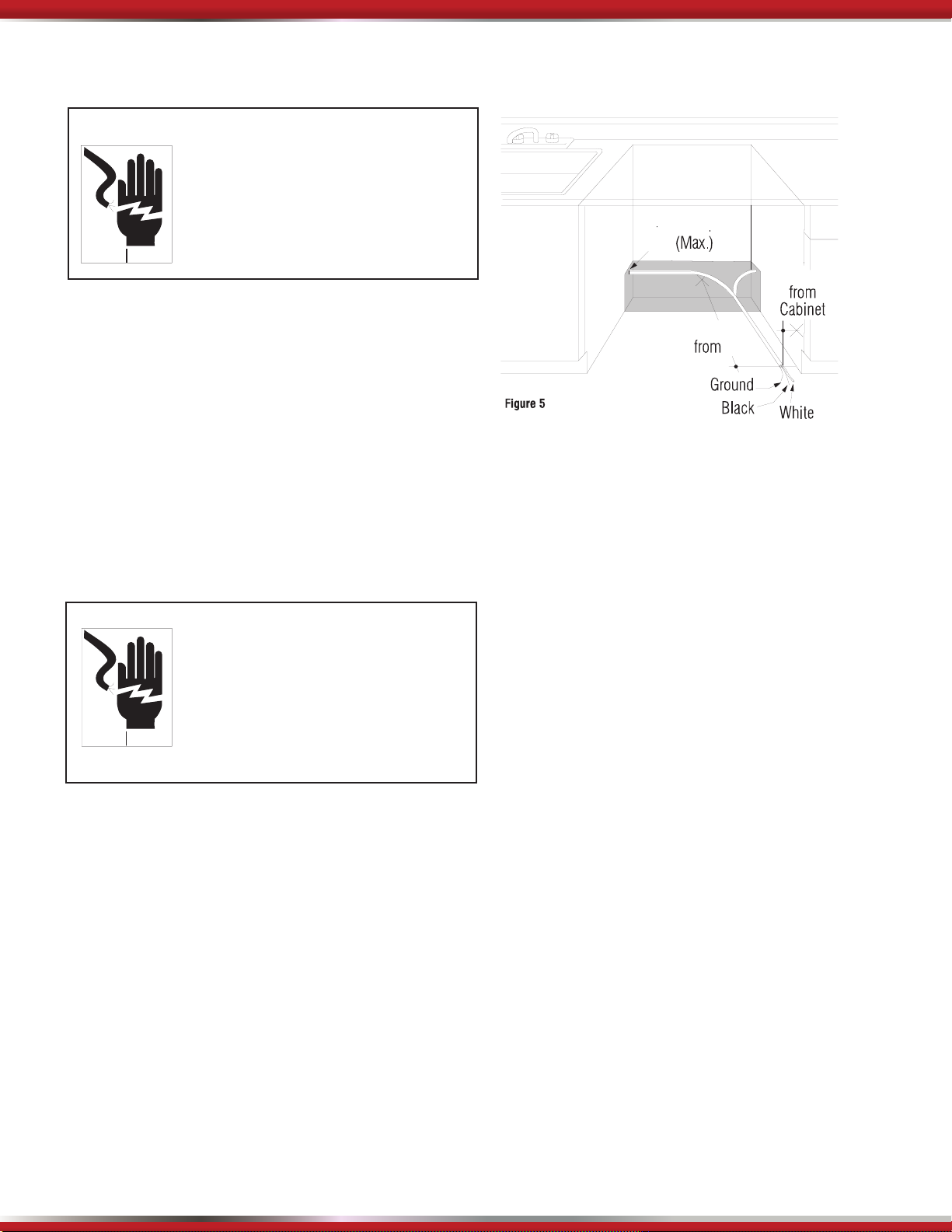
Electrical Connection to Dishwasher:
• The electrical connection is located on the right
front side of the dishwasher.
• The cable must be routed as shown in Fig. 5
Cable must extend a minimum of 24”(609.6mm) from the
rear wall.
4
 Loading...