

Kubuta BX1800, BX2200 Workshop Manual

WORKSHOP MANUAL
KiSC issued 07, 2006 A
TRACTOR
BX1800,BX2200

TO THE READER
KiSC issued 07, 2006 A
This Workshop Manual has been prepared to provide servicing personnel with
information on the mechanism, service and maintenance of KUBOTA Tractors BX1800
and BX2200. It is divided into two parts, “Mechanism” and “Servicing” for each section.
■ Mechanism
Information on the construction and function are included. This part should be
understood before proceeding with troubleshooting, disassembling and servicing.
■ Servicing
Under the heading “General” section comes general precautions, check and
maintenance and special tools. Other section, there are troubleshooting, servicing
specification lists, checking and adjusting, disassembling and assembling, and servicing
which cover procedures, pr ecauti ons , fac tor y spe cifi ca tion s and allowa bl e limits .
All information illustrations and specifications contained in this manual are based on
the latest product information available at the time of publication.
The right is reserved to make changes in all information at any time without notice.
January 2000
© KUBOTA Corporation 2000
BX1800 · BX2200, WSM
SAFETY FIRST
KiSC issued 07, 2006 A
SAFETY INSTRUCTIONS
SAFETY INSTRUCTIONS
This symbol, the industry’s “Safety Alert Symbol”, is used throughout this manual and on labels on
the machine itself to warn of the possibility of personal injury. Read these instructions carefully.
It is essential that you read the instructions and safety regulations before you attempt to repair or use
this unit.
DANGER : Indicates an imminently hazardous situation which, if not avoided, will result in
death or serious injury.
WARNING : Indicates a potentially hazardous situation which, if not avoided, could result in
death or serious injury.
CAUTION : Indicates a potentially hazardous situation which, if not avoided, may result in
minor or moderate injury.
■ IMPORTANT : Indicates that equipment or property damage could result if instructions are not
followed.
■ NOTE : Gives helpful information.
BEFORE SERVICING AND REPAIRING
• Read all instructions and safety instructions in this
manual and on your machine safety decals.
• Clean the work area and machine.
• Park the machine on a firm and level ground, and set
the parking brake.
• Lower the implement to the ground.
• Stop the engine, and remove the key.
• Disconnect the battery negative cable.
• Hang a “DO NOT OPERATE” tag in operator
station.
1
BX1800 · BX2200, WSM
KiSC issued 07, 2006 A
SAFETY INSTRUCTIONS
SAFETY STARTING
• Do not start the engine by shorting across starter
terminals or bypassing the safety start switch.
• Do not alter or remove any part of machine safety
system.
• Before starting the engine, make sure that all shift
levers are in neutral positions or in disengaged
positions.
• Never start the engine while standing on ground.
Start the engine only from operator’s seat.
SAFETY WORKING
• Do not work on the machine while under the influence
of alcohol, medication , or other substances or while
fatigued.
• Wear close fitting clothing and safety equipment
appropriate to the job.
• Use tools appropriate to the work. Makeshift tools,
parts, and procedures are not recommended.
• When servicing is performed together by two or more
persons, take care to perform all work safely.
• Do not work under the machine that is supported
solely by a jack. Always support the machine by
safety stands.
• Do not touch the rotating or hot parts while the engine
is running.
• Never remove the radiator cap while the engine is
running, or immediately after stopping. Otherwise, hot
water will spout out from radiator. Only remove
radiator cap when cool enough to touch with bare
hands. Slowly loosen the cap to first stop to relieve
pressure before removing completely.
• Escaping fluid (fuel or hydraulic oil) un der pressure
can penetrate the skin causing serious injury. Relieve
pressure before disconnecting hydraulic or fuel lines.
Tighten all connections before applying pressure.
AVOID FIRES
• Fuel is extremely flammable and explosive under
certain conditions. Do not smoke or allow flames or
sparks in your working area.
• To avoid sparks from an accidental short circuit,
always disconnect the battery negative cable first and
connect it last.
• Battery gas can explode. Keep sparks and open
flame away from the top of b attery, especially when
charging the battery.
• Make sure that no fuel has been spilled on the engine.
2
BX1800 · BX2200, WSM
KiSC issued 07, 2006 A
SAFETY INSTRUCTIONS
VENTILATE WORK AREA
• If the engine must be running to do some work, make
sure the area is well ventilated . Neve r run the eng ine
in a closed area. The exhaust gas contains poisonous
carbon monoxide.
PREVENT ACID BURNS
• Sulfuric acid in batte ry electrolyte is poisonou s. It is
strong enough to burn skin, clothing and cause
blindness if splashed into eyes. Keep electrolyte
away from eyes, hands and clothing. If you spill
electrolyte on yourself, flush with water, and get
medical attention immediately.
DISPOSE OF FLUIDS PROPERLY
• Do not pour fluids into the ground, down a drain, or
into a stream, pond, or lake. Observe relevant
environmental prot ectio n regulati ons whe n disp osing
of oil, fuel, coolant, electrolyte and other harmful
waste.
PREPARE FOR EMERGENCIES
• Keep a first aid kit and fire extingui sher handy at all
times.
• Keep emergency numbers for doctors, ambulance
service, hospital and fire department near your
telephone.
3
BX1800 · BX2200, WSM
KiSC issued 07, 2006 A
SAFETY INSTRUCTIONS
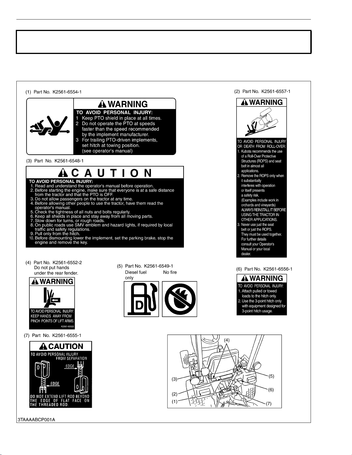
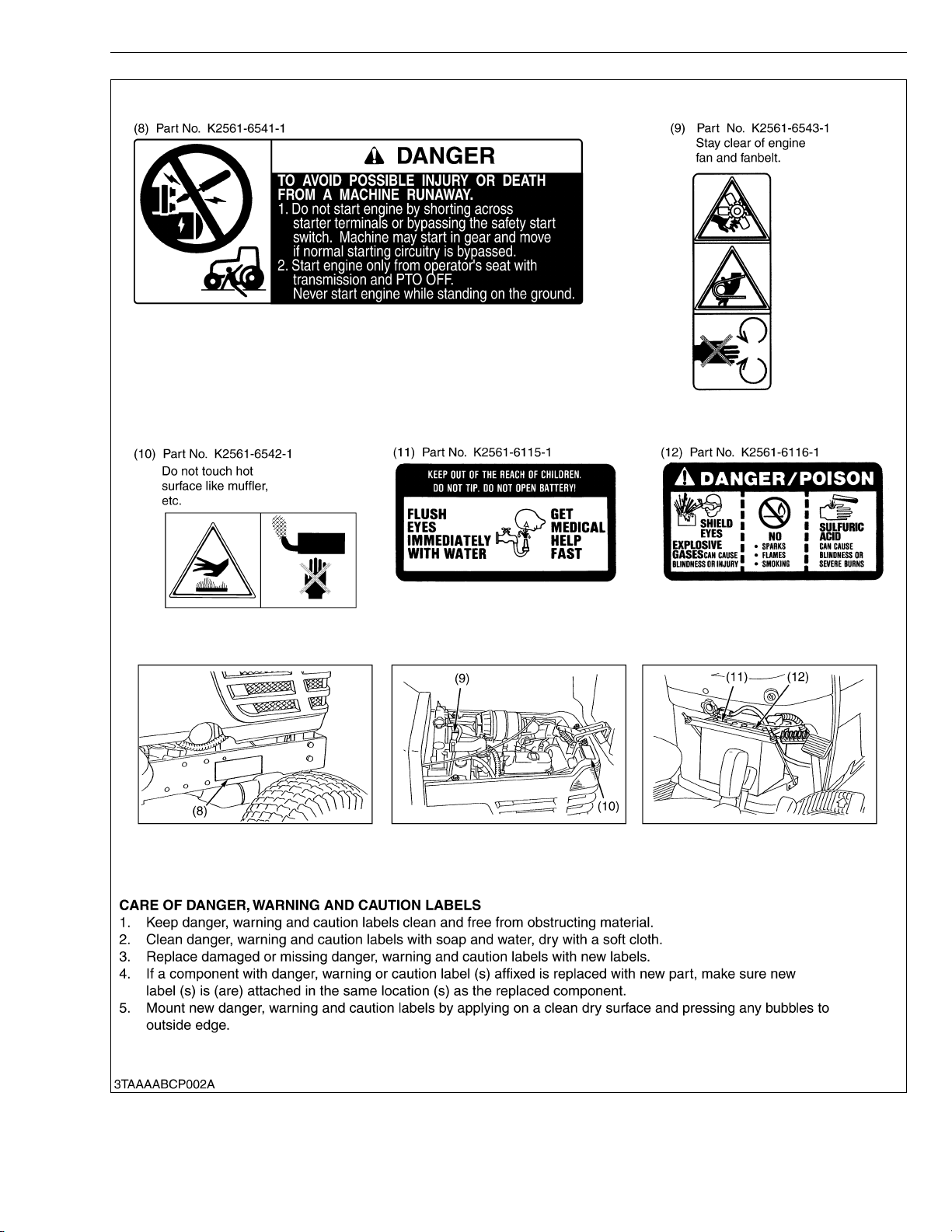
SAFETY DECALS
The following safety decals are installed on the machine.
If a decal becomes damaged, illegible or is not on the machine, replace it. The decal part number is listed in
the parts list.
4
BX1800 · BX2200, WSM
KiSC issued 07, 2006 A
SAFETY INSTRUCTIONS
5

BX1800 · BX2200, WSM
KiSC issued 07, 2006 A
SPECIFICATIONS
SPECIFICATIONS
Model BX1800 BX2200
PTO power 10.2 kW (13.7 HP)* 12.4 kW (16.7 HP)*
Maker KUBOTA
Model D722-E-BX D905-E-BX
Type Indirect Injection. Vertical, water-cooled, 4-cycle diesel
Number of cylinders 3
Bore and stroke 67 × 68 mm (2.64 × 2.68 in.) 72 × 73.6 mm (2.83 × 2.90 in.)
Total displacement 719 cm
Engine gross power (DIN) 13.4 kW (18.0 HP) 16.4 kW (22.0 HP)
Engine
Capacities
Dimensions
Weight 570 kg (1257 lbs) 590 kg (1301 lbs)
Travelling
system
Hydraulic
system
PTO system
NOTE: * Manufacture’s estimate
The company reserves the right to change the specifications without notice.
Rated revolution 53.3 r/s [3200 min
Maximum torque
Battery 12 V, CCA : 435 A, RC : 62 min. 12 V, CCA : 535 A, RC : 80 min.
Starting system Electric starting with cell starter, 12 V, 1.4 kW
Lubrication system Forced lubrication by trochoidal pump
Cooling system Pressurized radiator, forced circulation with water pump
Fuel Diesel fuel No. 2-D [above −10 °C (14 °F)], Diesel fuel No. 1 [below −10 °C (14 °F)]
Fuel tank 21 L (5.5 U.S.gals, 4.6 Imp.gals.)
Engine crankcase (with filter) 1.9 L (2.01 U.S.qts., 1.67 Imp.qts.) 2.5 L (2.64 U.S.qts., 2.20 Imp.qts.)
Engine coolant (with recovery tank) 2.9 L (3.06 U.S.qts., 2.55 Imp.qts.) 3.5 L (3.70 U.S.qts., 3.08 Imp.qts.)
Transmission case 10.1 L (2.7 U.S.gals, 2.2 Imp.gals.)
Front axle case 4.7 L (4.97 U.S.qts., 4.14 Imp.qts.)
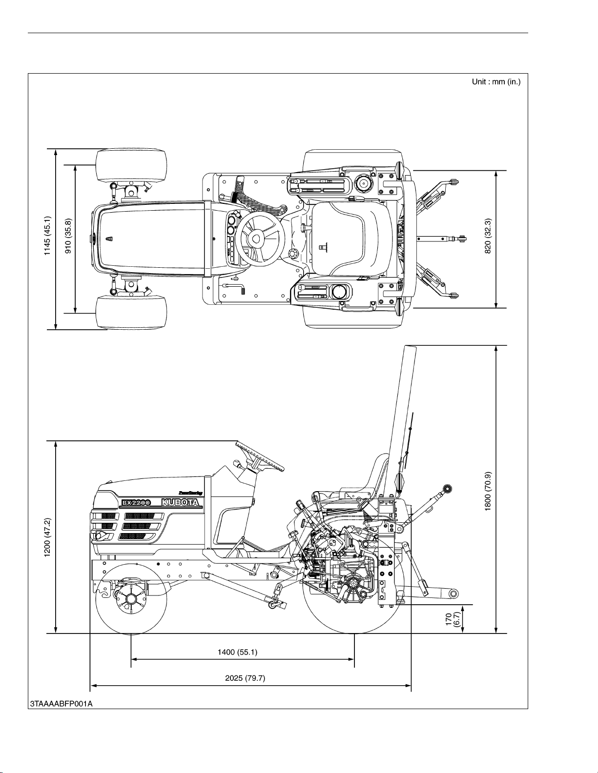
Overall length (without 3P) 2025 mm (79.7 in.)
Overall width 1145 mm (45.1 in.)
Overall height (with ROPS) 1800 mm (70.9 in.)
Overall height (top of steering wheel) 1200 mm (47.2 in.)
Wheel base 1400 mm (55.1 in.)
Minimum ground clearance (bottom of
hitch bracket)
Tread
Tires
Steering Hydrostatic power steering
Transmission Main-hydrostatic transmission, Range gear shift (2 forward and 2 reverse)
Brake Wet disc type
Min. turning radius (without brake) 2.3 m (7.5 feet)
Differential Bevel gear
Hydraulic control system Directional control, auto-return lever system
Pump capacity 21.0 L/min. (5.5 U.S.gals./min., 4.6 Imp.gals./min.)
Three point hitch SAE Category I
Max. lift force (24 in. behind lift points) 3040 N (310 kg, 684 lbs)
Clutch Wet type, multiple discs
Mid
Rear
Front 910 mm (35.8 in.)
Rear 820 mm (32.2 in.)
Front 18 × 8.50 – 8 (Turf)
Rear 26 × 12.00 – 12 (Turf)
PTO shaft
Revolution
PTO shaft
Revolution
41.5 N·m (4.23 kgf·m, 30.6 ft-lbs) / 36.7
to 43.3 r/s [2200 to 2600 min
3
(43.9 cu.in.) 898 cm3 (54.8 cu.in.)
-1
(rpm)]
-1
(rpm)]
170 mm (6.7 in.)
USA No. 5 (KUBOTA 10-tooth) involute spline
41.7 r/s [2500 min
9.0 r/s [540 min
-1
(rpm)] / engine 52.1 r/s [3125 min-1 (rpm)]
SAE 1-3/8, 6 splines
-1
(rpm)] / engine 51.1 r/s [3068 min-1 (rpm)]
54.9 N·m (5.6 kgf·m, 40.5 ft-lbs) / 36.7
to 43.3 r/s [2200 to 2600 min-1 (rpm)]
W1028103
6

BX1800 · BX2200, WSM
KiSC issued 07, 2006 A
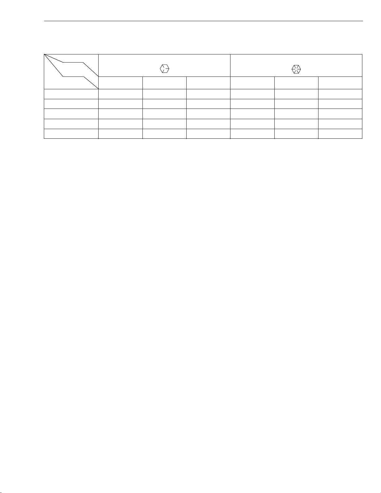
TRAVELLING SPEEDS
Model BX1800, BX2200
Tire size (Rear) 26 × 12.00 – 12
Range gear shift
lever
Low 0 to 5.9 0 to 3.7
Forward
High 0 to 13.0 0 to 8.1
Low 0 to 4.5 0 to 2.8
Reverse
High 0 to 10.0 0 to 6.2
The company reserves the right to change the spe cifi ca tion s with out notic e.
km/h mile/h
TRAVELLING SPEEDS
W1035065
7
BX1800 · BX2200, WSM
KiSC issued 07, 2006 A
DIMENSIONS
DIMENSIONS
8

G GENERAL
KiSC issued 07, 2006 A

GENERAL
KiSC issued 07, 2006 A
CONTENTS
1. TRACTOR IDENTIFICATION ......................................................................... G-1
2. GENERAL PRECAUTIONS ............................................................................ G-2
3. HANDLING PRECAUTIONS FOR ELECTRICAL PARTS AND WIRING..G-3
[1] WIRING...................................................................................................... G-3
[2] BATTERY................................................................................................... G-5
[3] FUSE.......................................................................................................... G-5
[4] CONNECTOR............................................................................................ G-5
[5] HANDLING OF CIRCUIT TESTER......................................................... G-6
4. LUBRICANTS, FUEL AND COOLANT ......................................................... G-7
5. TIGHTENING TORQUES ............................. ....... ...... ....... ...... ....... ...... ....... .... G- 8
[1] GENERAL USE SCREWS, BOLTS AND NUTS................................... G-8
[2] STUD BOLTS............................................................................................ G-8
[3] AMERICAN STANDARD SCREWS, BOLTS AND NUTS WITH UNC
OR UNF THREADS ................................................................................. G-9
6. MAINTENANCE CHECK LIST..................................................................... G-10
7. CHECK AND MAINTENANCE......... ...... ...... ....... ...... ....... ...... ....... ............... G-11
[1] DAILY CHECK........................................................................................ G-11
[2] CHECK POINTS OF INITIAL 50 HOURS........................................... G-12
[3] CHECK POINTS OF EVERY 50 HOURS........................................... G-14
[4] CHECK POINTS OF EVERY 100 HOURS......................................... G-15
[5] CHECK POINTS OF EVERY 200 HOURS......................................... G-20
[6] CHECK POINTS OF EVERY 300 HOURS......................................... G-21
[7] CHECK POINTS OF EVERY 400 HOURS......................................... G-22
[8] CHECK POINTS OF EVERY 500 HOURS......................................... G-23
[9] CHECK POINTS OF EVERY 800 HOURS......................................... G-23
[10]CHECK POINTS OF EVERY 1500 HOURS....................................... G-23
[11]CHECK POINTS OF EVERY 3000 HOURS....................................... G-23
[12]CHECK POINTS OF EVERY 1 YEAR................................................ G-23
[13]CHECK POINTS OF EVERY 2 YEARS.............................................. G-24
[14]OTHERS .................................................................................................. G-25
8. SPECIAL TOOLS.......................................................................................... G-27
[1] SPECIAL TOOLS FOR ENGINE .......................................................... G-27
[2] SPECIAL TOOLS FOR TRACTOR....................................................... G-34
9. TIRES............................................................................................................. G-35
[1] TIRE PRESSURE................................................................................... G-35
[2] TREAD..................................................................................................... G-35
[3] TIRE LIQUID INJECTION...................................................................... G-36
10. IMPLEMENT LIMITATIONS.......................................................................... G-38
BX1800 · BX2200, WSM
KiSC issued 07, 2006 A
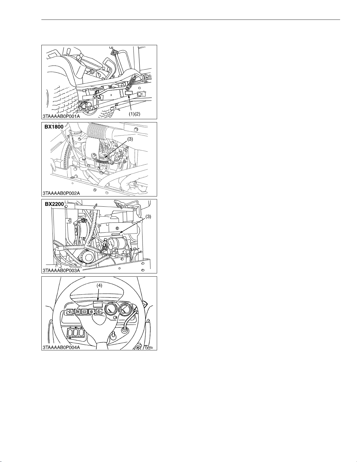
1. TRACTOR IDENTIFICATION
When contacting your loca l KUBOTA distr ibutor, alway s specify
engine serial number, tractor serial number and hour meter reading.
(1) Tractor Identification Plate
(2) Tractor Serial Number
G GENERAL
(3) Engine Serial Number
(4) Hour Meter
W1010590
G-1
BX1800 · BX2200, WSM
KiSC issued 07, 2006 A
2. GENERAL PRECAUTIONS
• During disa ssembly, ca refully ar range removed parts in a cle an
area to prevent confusion later. Bolts and nuts should be
installed in their original position to prevent reassembly errors.
• When special tools are requi red, use KUBOT A genuine speci al
tools. Special tools which are not frequently used should be
made according to the drawings provided.
• Before disassembling or servicing electrical wires, always
disconnect the ground cable from the battery first.
• Remove oil and dirt from parts before measuring.
• Use only KUBOTA genuine parts for parts replacement to
maintain tractor performance and to assure safety.
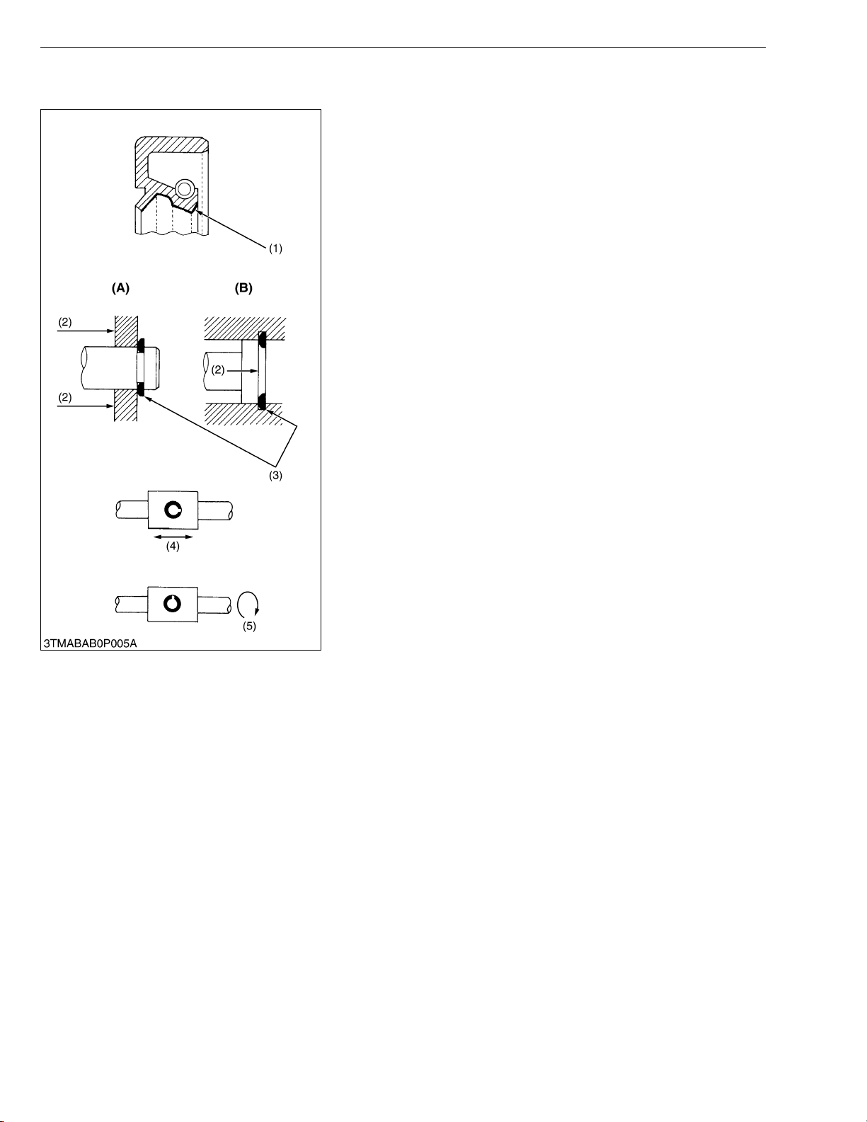
• Gaskets and O-rings must be replaced during reassembly.
Apply grease to new O-rings or oil seals before assembling.
See the figure left side.
• When reassem bling external snap rings or inte rnal snap rings,
they must be positioned so that sharp edge faces against the
direction from which a force is applied. See the figure left side.
• When insert ing spring pins, their splits must face the direction
from which a force is applied. See the figure left side.
• To prevent dam age to the hydraulic s ystem, use only sp ecified
fluid or equivalent.
(1) Grease
(2) F orce
(3) S harp Edge
(4) Axial Force
(5) Rotating Movement
G GENERAL
(A) External Snap Ring
(B) Internal Snap Ring
W10109040
G-2
BX1800 · BX2200, WSM
IMPORTANT■
KiSC issued 07, 2006 A
G GENERAL
3. HANDLING PRECAUTIONS FOR ELECTRICAL PARTS
AND WIRING
To ensure safety and prevent damage to the machine and
surrounding equipm ent, heed the following pr ecautions in handling
electrical parts and wiring.
• Check electrical wiring for damage and loosened
connection every year. To this end, educate the customer to
do his or her own check and at the s ame time recommend
the dealer to perform periodic check for a fee.
• Do not attempt to modify or remodel any electrical parts and
wiring.
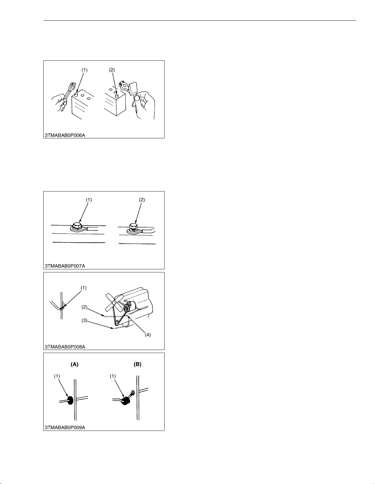
• When removing th e ba tter y cab le s, dis co nn ect t he n egat ive
cable first. When in stalling the b attery cables, c onnect the
positive cable first.
(1) Negative Terminal (2) Positive Terminal
W10111140
[1] WIRING
• Securely t ighten wiring terminals.
(1) Correct
(Securely Tighten)
(2) Incorrect
(Loosening Leads to Faulty Contact)
W10112160
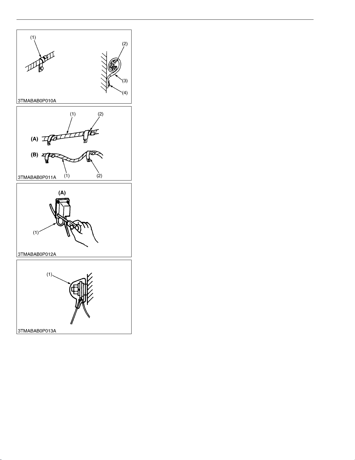
• Do not let wiring contact dangerous part.
(1) Dangerous Part
(2) Wiring (Incorrect)
(3) Wiring (Correct)
(4) Dangerous Part
• Securely insert grommet.
(1) Grommet (A) Correct
(B) Incorrect
W10113130
W10113880
G-3
BX1800 · BX2200, WSM
KiSC issued 07, 2006 A
G GENERAL
• Securely clamp, being careful not to damage wiring.
(1) Clamp
• Wind Clamp Spirally
(2) Wire Harness
(3) Clam p
(4) Welding Dent
W10114580
• Clamp wiring so that there is no twist, unnecessary sag, or
excessive tension, except for movable part, where sag be
required.
(1) Wiring
(2) Clamp
(A) Correct
(B) Incorrect
W10115870
• In installing a part, take care not to get wiring caught by it.
(1) Wiring (A) Incorrect
W10116700
• After installing wiring, check protection of terminals and clamped
condition of wiring, only connect battery.
(1) Cover
• Securely Install Cover
W10117350
G-4
BX1800 · BX2200, WSM
KiSC issued 07, 2006 A
[2] BATTERY
[3] FUSE
G GENERAL
• Take care not to confuse positive and negative terminal posts.
• When removing b attery cables, disconnect negative cable first.
When installing battery cables, check for polarity and connect
positive cable first.
• Do not install a ny battery with capacity other than is specified
(Ah).
• After connecting cables to battery terminal posts, apply high
temperature grease to them a nd sec urely in stall t erminal covers
on them.
• Do not allow dirt and dust to collect on battery.
CAUTION
• Take care not to let battery liquid spill on your skin and
clothes. If contaminated, wash it off with water immediately.
• Before recharging the battery, remove it from the machine.
• Before recharging, remove cell caps.
• Do recharging in a well- ventilated place where there is no
open flame nearby, as hydrogen gas and oxygen are formed.
W10118160
[4] CONNECTOR
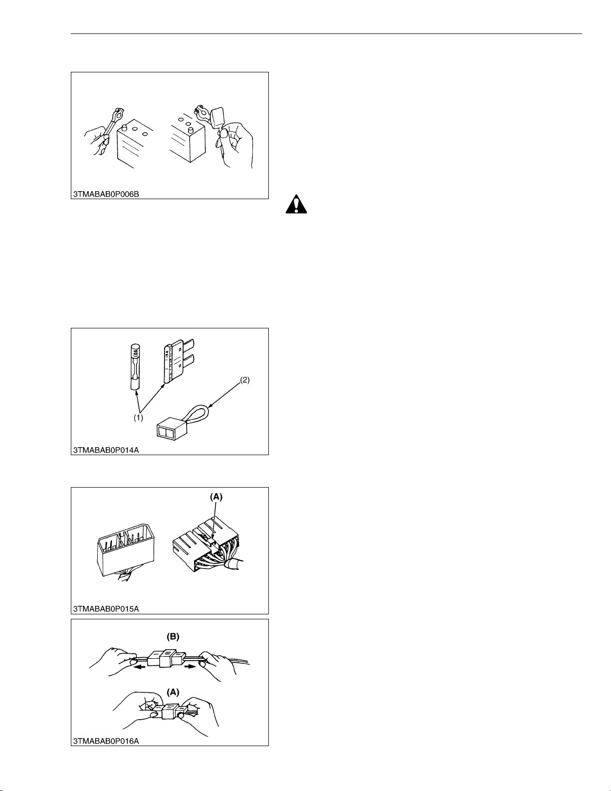
• Use fuses with specified capacity.
Neither too large or small capacity fuse is acceptable.
• Never use steel or copper wire in place of fuse.
• Do not install working light, radio set, etc. on machine which is not
provided with reserve power supply.
• Do not install accessories if fuse capacity of reserve power
supply is exceeded.
(1) Fuse (2) Fusible Link
W10120920
• For connector with lock, push lock to separate.
(A) Push
W10122110
• In separating connectors, do not pull wire harnesses.
• Hold connector bodies to separate.
(A) Correct (B) Incorrect
W10122720
G-5
BX1800 · BX2200, WSM
KiSC issued 07, 2006 A
G GENERAL
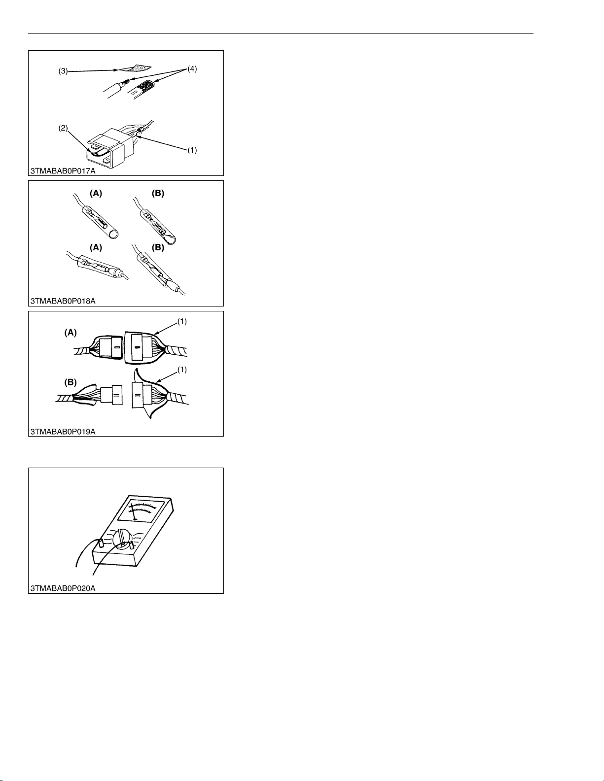
• Use sandpaper to remove rust from terminals.
• Repair deformed terminal. Make certain there is no terminal
being exposed or displaced.
(1) Exposed Terminal
(2) Bend Terminal
(3) Sandpaper
(4) Rust
W10123460
• Make certain that there is no female connector being too open.
(A) Correct (B) Incorrect
W10124300
• Make certain plastic cover is large enough to cover whole
connector.
(1) Cover (A) Correct
[5] HANDLING OF CIRCUIT TESTER
• Use tester correctly following manual provided with tester.
• Check for polarity and range .
(B) Incorrect
W10125190
W10126840
G-6

BX1800 · BX2200, WSM
KiSC issued 07, 2006 A
4. LUBRICANTS, FUEL AND COOLANT
G GENERAL
No. Place
1 Fuel tank
Cooling system
2
with recovery tank
3 Engine crankcase
4 Transmission case
5 Front axle case
No. Place No. of greasing point Capacity Type of grease
6 Battery terminal 2 Moderate amount
* KUBOTA original transmission hydraulic fluid.
BX1800 BX2200
3.06 U.S.qts.
2.55 Imp.qts.
2.01 U.S.qts.
1.67 Imp.qts.
Capacity
5.5 U.S.gals.
4.6 Imp.gals.
2.9 L
1.9 L
2.7 U.S.gals.
2.2 Imp.gals.
4.97 U.S.qts.
4.14 Imp.qts.
21.0 L
3.70 U.S.qts.
3.08 Imp.qts.
2.64 U.S.qts.
2.20 Imp.qts.
10.1 L
4.7 L
3.5 L
2.5 L
Greasing
Lubricants, fuel and coolant
No. 2-D diesel fuel
No. 1-D diesel fuel if temperature is below −10 °C
(14 °F)
Fresh clean water with anti-freeze
Engine oil : API Service CC or CD
Below 0 °C (32 °F) : SAE10W, 10W-30 or 10W-40
0 to 25 °C (32 to 77 °F): SAE20, 10W-30 or
10W-40
Above 25 °C (77 °F): SAE30, 10W-30 or 10W-40
KUBOTA SUPER UDT fluid*
KUBOTA SUPER UDT fluid* or SAE80, 90 gear
oil
Multipurpose type
grease
G-7

BX1800 · BX2200, WSM
KiSC issued 07, 2006 A
G GENERAL
5. TIGHTENING TORQUES
[1] GENERAL USE SCREWS, BOLTS AND NUTS
Screws, bolts and nuts whos e tightening torques are not spec ified i n this W orkshop Ma nual sho uld be tig htened
according to the table below.
Indication on top of
bolt
Material of bolt SS400, S20C S43C, S48C
Material of opponent
part
Unit
Diameter
M6
(6 mm, 0.24 in.)
M8
(8 mm, 0.31 in.)
M10
(10 mm, 0.39 in.)
M12
(12 mm, 0.47 in.)
M14
(14 mm, 0.55 in.)
M16
(16 mm, 0.63 in.)
M18
(18 mm, 0.71 in.)
M20
(20 mm, 0.79 in.)
No-grade or 4T 7T 9T
SCr435,
SCM435
Ordinariness Aluminum Ordinariness Aluminum Ordinariness
N·m kgf·m ft-lbs N·m kgf·m ft-lbs N·m kgf·m ft-lbs N·m kgf·m ft-lbs N·m kgf·m ft-lbs
7.85
0.80
5.79
7.85
0.80
5.79
9.81
1.00
7.24
7.85
0.80
5.79
12.3
to
9.31
17.7
to
20.5
39.3
to
45.1
62.8
to
72.5
108
to
125
167
to
191
246
to
284
334
to
392
to
0.95
1.8
to
2.1
4.0
to
4.6
6.4
to
7.4
11.0
to
12.8
17.0
to
19.5
25.0
to
29.0
34.0
to
40.0
to
6.87
13.1
to
15.1
29.0
to
33.2
46.3
to
53.5
79.6
to
92.5
123
to
141
181
to
209
246
to
289
to
to
to
8.82
0.90
6.50
16.7
19.6
31.4
34.3
1.7
12.3
to
to
2.0
3.2
to
3.5
–––
–––
–––
–––
–––
to
14.4
23.2
to
to
25.3
to
11.2
23.6
to
27.4
48.1
to
55.8
77.5
to
90.2
124
to
147
197
to
225
275
to
318
368
to
431
to
1.15
2.4
to
2.8
4.9
to
5.7
7.9
to
9.2
12.6
to
15.0
20.0
to
23.0
28.0
to
32.5
37.5
to
44.0
to
8.31
17.4
to
20.2
35.5
to
41.2
57.2
to
66.5
91.2
to
108
145
to
166
203
to
235
272
to
318
to
to
to
8.82
0.90
6.50
17.7
20.5
39.3
44.1
62.8
72.5
1.8
13.1
to
to
2.1
4.0
to
4.5
6.4
to
7.4
–––
–––
–––
–––
to
15.1
29.0
to
to
32.5
46.3
to
to
53.5
to
14.2
29.5
to
34.3
60.9
to
70.6
103
to
117
167
to
196
260
to
304
344
to
402
491
to
568
1.25
to
1.45
3.0
to
3.5
6.2
to
7.2
10.5
to
12.0
17.0
to
20.0
26.5
to
31.0
35.0
to
41.0
50.0
to
58.0
W1034542
9.05
to
10.4
21.7
to
25.3
44.9
to
52.0
76.0
to
86.7
123
to
144
192
to
224
254
to
296
362
to
419
[2] STUD BOLTS
Material of opponent
part
Unit
Diameter
M8
(8 mm, 0.31 in.)
M10
(10 mm, 0.39 in.)
M12
(12 mm, 0.47 in.)
Ordinariness Aluminum
N·m kgf·m ft-lbs N·m kgf·m ft-lbs
11.8
to
15.6
24.6
to
31.3
29.5
to
49.0
1.2
to
1.6
2.5
to
3.2
3.0
to
5.0
8.68
8.82
to
11.5
18.1
23.1
21.7
36.1
to
11.8
19.7
to
to
25.4
to
31.4 3.2 23.1
0.90
to
1.2
2.0
to
2.6
6.51
to
8.67
14.5
to
18.8
W10481390
G-8
BX1800 · BX2200, WSM
KiSC issued 07, 2006 A
G GENERAL
[3] AMERICAN STANDARD SCREWS, BOLTS AND NUTS WITH UNC OR
UNF THREADS
Grade
Unit
Nominal Diameter
5/16 23.1 to 27.8 2.35 to 2.84 17.0 to 20.5 32.5 to 39.3 3.31 to 4.01 24.0 to 29.0
3/8 47.5 to 57.0 4.84 to 5.82 35.0 to 42.0 61.0 to 73.2 6.22 to 7.47 45.0 to 54.0
1/2 108.5 to 130.2 11.07 to 13.29 80.0 to 96.0 149.2 to 179.0 15.22 to 18.27 110.0 to 132.0
9/16 149.2 to 179.0 15.22 to 18.27 110.0 to 132.0 217.0 to 260.4 22.14 to 26.57 160.0 to 192.0
5/8 203.4 to 244.1 20.75 to 24.91 150.0 to 180.0 298.3 to 358.0 30.44 to 36.53 220.0 to 264.0
SAE GR.5 SAE GR.8
N·m kgf·m ft-lbs N·m kgf·m ft-lbs
W1022485
G-9

BX1800 · BX2200, WSM
IMPORTANT■
KiSC issued 07, 2006 A
6. MAINTENANCE CHECK LIST
G GENERAL
Period
No.
Item
1 Engine oil C hange ★✩ ✩ ✩ ✩
2 Engine oil filter Replace ★✩ ✩ ✩ ✩ G-12
3 T ransmission oil filter Replace ★✩ ✩ G-13
4 T ransmission fluid Change ★✩ ✩ G-13
5 T ransmission strainer Clean ✩✩ G-22
6 Front axle case oil Change ✩✩ G-22
7 Front axle pivot Adjust ✩✩ G-22
8 Engine start system Check ✩✩✩✩
9 Greasing – ✩✩✩✩
10 Wheel bolt torque Check ✩✩✩✩
11 Battery condition Check ✩✩✩✩
12 Air cleaner element
13 Fuel filter element
14 Fan belt Adjust ✩✩✩✩
15 HST neutral spring Adjust ✩✩✩✩
16 Brake Adjust ✩✩✩✩
17 Radiator hose and clamp
18 Power steering oil line
19 Fuel line
20 Intake air line
21 Toe-in Adjust ✩✩✩✩ G-21
22 Engine valve clearance Adjust ✩ 1-S22
Fuel injection nozzle
23
injection pressure
24 Injection pump Check ✩ @1-S30
25 Cooling system Flush ✩ G-24
26 Coolant Change ✩
27 Fuel system Bleed
28 Fuse Replace G-26
29 Light bulb Replace G-26
Clean ✩✩✩✩
Replace ✩ *2 G-17
Check ✩✩✩✩
Replace
Check ✩✩✩✩ G-20
Replace ✩ G-20
Check ✩✩✩✩ G-20
Replace ✩ G-20
Check ✩✩✩✩
Replace ✩ G-18
Check ✩✩✩✩ G-21
Replace ✩ *3 G-21
Check ✩✩ @1-S20
50 10015020025030035040045050055060065070075080015003000
Indication on hour meter
✩
✩
✩
✩
✩
✩
✩
✩✩✩✩✩✩✩
✩
✩
✩✩✩✩✩✩✩
✩
✩
✩✩✩✩✩✩✩
✩
✩
✩
✩
✩
✩
✩
✩
✩
✩
✩
✩
✩
✩
✩
✩
✩
✩
✩
✩ G-12
✩ G-14
✩ G-14
✩ G-15
✩
✩ *4 G-15
✩
✩ *1
✩
✩
✩
✩ G-18
✩
✩ G-19
✩
✩ G-19
✩
✩
After
purchase
1
year2 years
Service as
required
Impor-
tant
@
@
@
Refer-
ence
page
G-17
G-18
G-18
G-18
G-24
G-25
• The jobs indicated by ★ must be done after the first 50 hours of operation.
• *1 : Air cleaner should be cleaned more often in dusty conditions than in normal conditions.
• *2 : Every year or every 6 times of cleaning.
• *3 : Replace only if necessary.
• *4 : When the battery is used for less than 100 hours per year, check the fluid level annually.
• The items listed above (@ marked) are registered as emission related critical parts by KUBOTA in the U.S.EPA nonroad emission
regulation. As the engine owner, you are responsible for the performance of the requi red maintenance on the en gine according t o
the above instruction.
Please see the Warranty Statement in detail.
W1035769
G-10

BX1800 · BX2200, WSM
KiSC issued 07, 2006 A
G GENERAL
7. CHECK AND MAINTENANCE
CAUTION
• Be sure to check and service the tractor on a flat place with engine shut off, the parking brake on and chock
the wheels.
[1] DAILY CHECK
To prevent trouble from occurring, it is important to kno w the condition of the tractor. Che ck the following items
before starting.
Checking
• Check areas where previous trouble was experienced.
• Walk around the tractor.
1. Check the tire press ure, and check for wear and damage.
2. Check for oil and water leaks.
3. Check the engine oil lev el.
4. Check the transmi ssio n flui d level.
5. Check the coola nt lev el .
6. Check the condition of seat belt and ROPS attaching hardware.
7. Check and clean the radiator screen and grill.
8. Check the bolts and nuts of tires are tight.
9. Check the number plate or SMV emblem for damage and cleaner replace as necessary if equipped.
10.Care of danger, warning and caution labels.
11.Clean around the exhaust manifold and the muffler of the engine.
• While sitting in the operator’s seat.
1. Check the HST pedal and brake pedals.
2. Check the parking brake.
3. Check the steering wheel.
• Turning the key switch.
1. Check the performance of the easy checker lights.
2. Check head lights, tail lights and hazard lights. Clean if necessary.
3. Check the performance of the meters and gauges.
• Starting the engine.
1. Check to see that the lights on the Easy Checker go off.
2. Check the color of the exhaust gas.
3. Check the brakes for proper operation.
G-11
BX1800 · BX2200, WSM
■
IMPORTANT■
KiSC issued 07, 2006 A
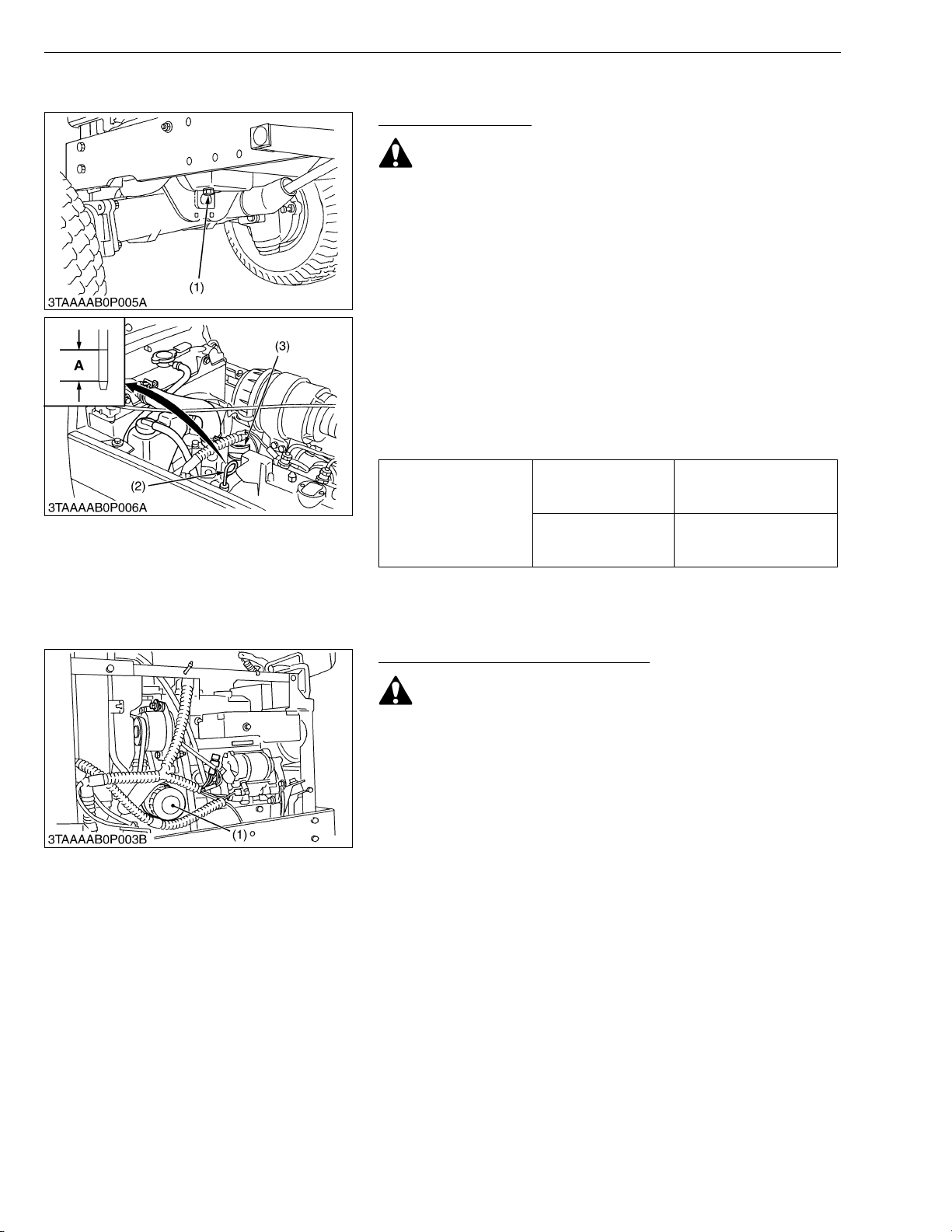
[2] CHECK POINTS OF INITIAL 50 HOURS
Changing Engine Oil
CAUTION
• Be sure to stop the engine before changing engine oil.
1. Start and warm up the engine for approx. 5 minutes.
2. Place an oil pan underneath the engine.
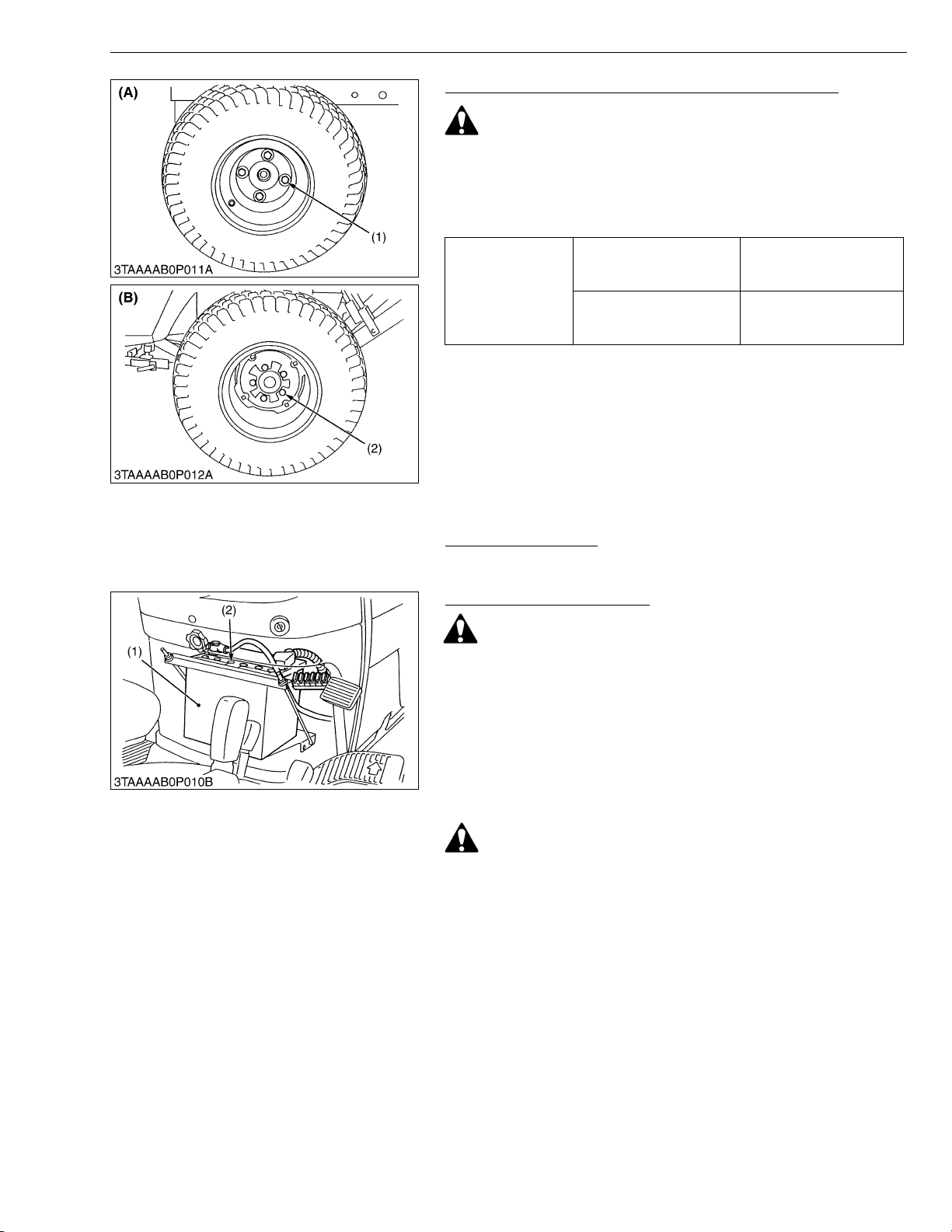
3. To drain the us ed oi l, remov e the d rain plug (1 ) at th e bottom of
the engine and drain the oil completely.
4. Screw in the drain plug (1).
5. Fill new oil up to upper line on the dipstick (2).
IMPORTANT
• When using an oil of different manufacture or viscosity from
the previous one, remove all of the old oil.
• Never mix two different types of oil.
• Use the proper SAE Engine Oil according to ambient
temperatures.
• Refer to “LUBRICANTS, FUEL AND COOLANT”. (See page
G-7.)
Engine oil capacity
BX1800
BX2200
G GENERAL
1.9 L
2.01 U.S.qts.
1.67 Imp.qts.
2.5 L
2.64 U.S.qts.
2.20 Imp.qts.
(1) Drain Plug
(2) Dipstick
(3) Oil Inlet
A : Oil level is acceptable within this
range.
W1014065
Replacing Engine Oil Filter Cartridge
CAUTION
• Be sure to stop the engine before changing oil filter
cartridge.
1. Remove the oil filter cartridge with the filter wrench.
2. Apply a slight coat of oil onto the cartridge gasket.
3. To install the new cartridge, screw it in by hand. Over tightening
may cause deformation of rubber gasket.
4. After the new cartridge has been replaced, the engine oil
normally decrease a little. Thus see that the engine oil does not
leak through the seal and be sure to read the oil level on the
dipstick. Then, replenish the engine oil up to the specified level.
• To prevent serious damage to the engine, replacement
element must be highly efficient. Use only a KUBOTA
genuine filter or its equivalent.
(1) Engine Oil Filter Cartridge
W1014316
G-12
BX1800 · BX2200, WSM
■
IMPORTANT■
KiSC issued 07, 2006 A
G GENERAL
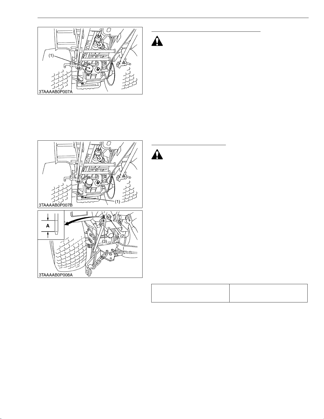
Replacing Transmission Oil Filter Cartridge
CAUTION
• Be sure to stop the engine before changing the oil filters.
1. Remove the oil filter cartridge by using a filter wrench.
2. Apply a slight coat of oil onto the cartridge gasket.
3. To install the new cartridge, screw it in by hand. Over tightening
may cause deformation of rubber gasket.
4. After the new cartridge has been replaced, the transmission fluid
level will normally decrease slightly. Make sure that the
transmission fluid does not leak through the seal. Check the fluid
level.
IMPORTANT
• To prevent serious damage to the hydraulic system. Use
only a genuine KUBOTA filter or its equivalents.
(1) Transmission Oil Filter Cartridge
W1014458
Changing Transmission Fluid
CAUTION
• Be sure to s top the engine be fore ch anging t he transm ission
fluid.
1. Place an oil pan under the tractor.
2. Remove the drain plugs (1) at the bottom of the transmission
case and drain the oil completely.
3. After draining, screw in the drain plug.
4. Fill new oil from filling port after removing the filling plug (2) up to
the upper notch on the dipstick.
5. After running the engine for a few minutes, stop it and check the
oil level again, if low, add oil to prescribed level.
• Use only multi-grade transmission oil. Use of other oils may
damage the transmission or hydraulic system.
Refer to “LUBRICANTS, FUEL AND COOLANT”. (See page
G-7.)
• Never work the tractor immediately after changing the
transmission oil. Keeping the engine at medium speed for a
few minutes to prevents damage to the transmission.
• Do not mix different blands oil together.
Transmission fluid capacity
(1) Drain Plug
(2) Filling Plug
(3) Dipstick
10.1 L
2.7 U.S.gals.
2.2 Imp.gals.
A : Oil level is acceptable within this
range.
W1014665
G-13
BX1800 · BX2200, WSM
KiSC issued 07, 2006 A
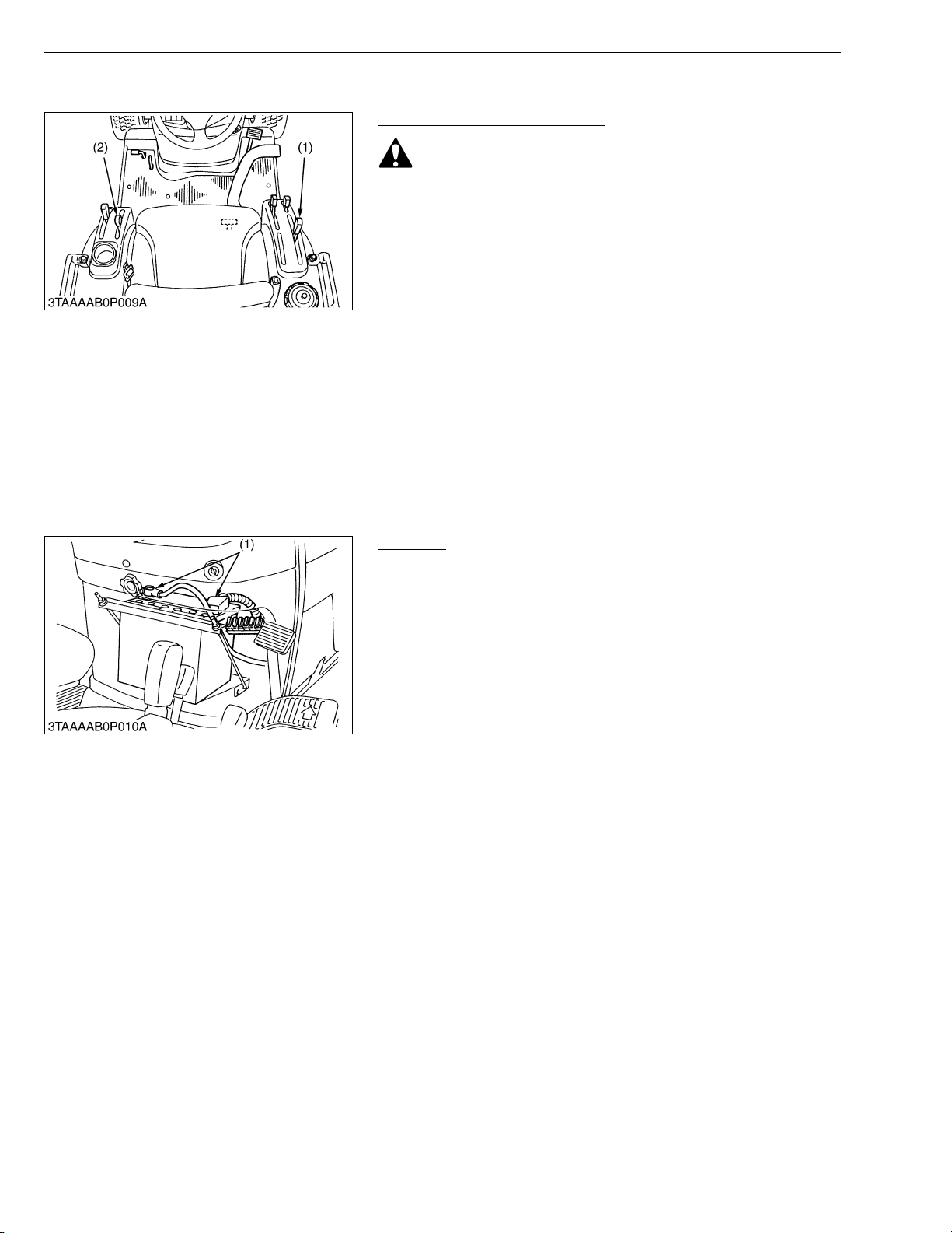
[3] CHECK POINTS OF EVERY 50 HOURS
Checking Engine Start System
CAUTION
• Do not allow anyone near the tractor whil e testing.
• If the tractor does not pass the test do not operate the
tractor.
■ Preparation before testing.
1. Sit on operator’s seat.
2. Set the parking brake and stop the engine.
3. Shift the range gear shift lever in “NEUTRAL” position.
4. Shift the PTO clutch lever to “OFF” position.
■ Test 1 : Safety switch on the range gear shift linkage
1. Shift the range gear shift lever to “LOW” or “HIGH” position.
2. Turn the key to “START” position.
3. The engine must not crank.
■ Test 2 : Safety switch on the PTO clutch lever
1. Shift the range gear shift lever to “NEUTRAL” posit ion .
2. Shift the PTO clutch lever to “ON” position.
3. Turn the key to “START” position.
4. The engine must not crank.
(1) Range Gear Shift Lever (2) PTO Clutch Lever
Greasing
1. Apply a small amount of grease to the battery terminals (1).
(1) Battery Terminal
G GENERAL
W1014904
W1015242
G-14
BX1800 · BX2200, WSM
KiSC issued 07, 2006 A
G GENERAL
Checking Wheel Mounting Screws Tightening Torque
CAUTION
• Never operate tractor with a loose rim, wheel, or axle.
• Any time screws are loosened, retighten to specified torque.
• Check all screws frequently and keep them tight.
1. Check wheel screws regularly especially when new. If there are
loosened, tighten as follows.
Front wheel mounting
screws
Tightening torque
Rear wheel mounting
screws
149.2 to 179.0 N·m
15.3 to 18.2 kgf·m
110 to 132 ft-lbs
108.5 to 130.2 N·m
11.1 to 13.2 kgf·m
80 to 96 ft-lbs
(1) Front Wheel Mounting Screw
(2) Rear Wheel Mounting Screw
[4] CHECK POINTS OF EVERY 100 HOURS
Changing Engine Oil
1. See page G-12.
Checking Battery Condition
DANGER
To avoid the possibility of battery explosion:
For the refillable type battery, follow the instructions below.
• Do not use or charge the refillable type battery if the fluid
level is below the LOWER (lower limit level) mark.
Otherwise, the battery component parts may prematurely
deteriorate, which ma y shorten the batte ry’s service life or
cause an explosion. Check the fluid level regularly and add
distilled water as required so that the fluid level is between
the UPPER and LOWER levels.
(A) Front
(B) Rear
W1015311
W1015501
CAUTION
• Never remove the vent plugs while the engine is running.
• Keep electrolyte away fr om eyes, h and s and clothe s. If you
are spattered with it, wash it away completely with water
immediately and get medical attention.
• Wear eye protection and rubber gloves when working
around battery.
1. Mishandling the battery shortens the service life and adds to
maintenance costs.
2. The original battery is maintenance free type battery, but need
some servicing.
If the battery is weak, the engine is difficult to start and the lights
become dim. It is important to check the battery periodically.
(1) Battery (2) Vent Plug
W1015551
G-15
BX1800 · BX2200, WSM
KiSC issued 07, 2006 A
G GENERAL
■ Battery Charging
CAUTION
• When the battery is being activated, hydrogen and oxygen
gases in the battery are extremely explosive. Keep open
sparks and flames away from the battery at all times,
especially when charging the battery.
• When charging the battery, ensure the vent caps are
securely in place (if equipped).
• When disconnecting the cable from the battery, start with
the negative terminal first.
When connecting the cable to the battery, start with the
positive terminal first.
• Never check battery charge by placing a metal object across
the posts.
Use a voltmeter or hydrometer.
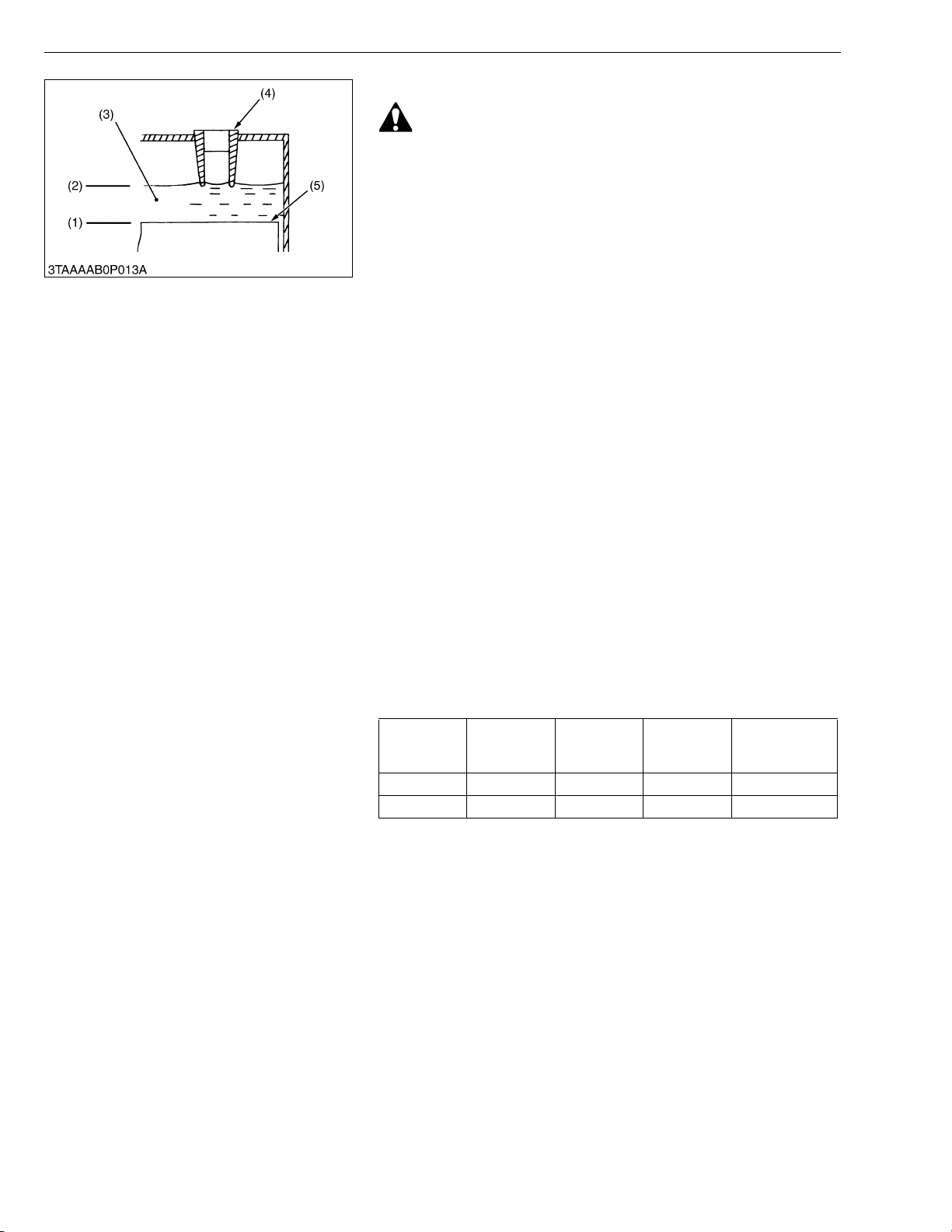
1. Make sure each e lec trol yte lev el is to the bottom of vent wells, if
necessary add distilled water in a well-ventilated area.
2. The water in the electrolyte evaporates during recharging. Liquid
shortage damage s the battery . Excessiv e liquid s pills over a nd
damages the tractor body.
3. To slow charge the battery, connect the battery positive terminal
to the charger positive terminal and the negative to the negative,
then recharge in the standard fashion.
4. A boost ch arge is only f or emergen cies. It will par tially c harges
the battery at a high rate and in a short time.
When using a boost-charged battery, it is necessary to recharge
the battery as early as possible.
Failure to do this will shorten the battery’s service life.
5. When the specific gravity of electrolyte become betwee n 1.27
and 1.29 charge has completed.
6. When exchanging an old battery into new one, use battery of
equal specification shown in table 1.
Table 1
Reserve
Tractor Type Battery Type Volts (V)
BX1800 26/26R 12 62 435
BX2200 526RA 12 80 535
Capacity
(min.)
Cold Cranking
Amps
■ Direction for Storage
1. When storing the tractor for long periods of time, remove the
battery from tractor, adjust the electrolyte to the proper level and
store in a dry place out of direct sunlight.
2. The battery self-discharges while it is stored.
Recharge it once every three months in hot se asons and once
every six months in cold seasons.
(1) Lowest Level
(2) Highest Level
(2) Electrolyte
(4) Vent Well
(5) Separator
W1019057
G-16

BX1800 · BX2200, WSM
IMPORTANT■
KiSC issued 07, 2006 A
G GENERAL
Cleaning Air Cleaner Element
1. Remove the air cleaner cover (2) and element (1).
2. Clean the element if:
- When dry dust adheres to the element, blow compressed air
from the inside, turn ing the element. Pres su re o f c omp r ess ed
2
air must be under 205 kPa (2.1 kgf/cm
, 30 psi).
- When carbon or oil adheres to the element, soak th e element
in detergent for 15 minutes then wash it several times in water,
rinse with clean water and dry it naturally. After element is fully
dried, inspect inside of the element with a light and check if it is
damaged or not.
3. Replace the element (1) once a year or after every six ti mes of
cleaning, whichever comes first.
• The air cleaner uses a dry element, never apply oil.
• Do not run the engine with filter element removed.
• Be sure to refit the dust cup with the arrow ↑ upright. If the
dust cup is improperly fitted, evacuator valve will not
function and dust will adhere to the element.
■ Evacuator Valve
Open the evacuator valve once a week under ordinary conditions
or daily when used in a dusty place to get rid of large particles of dust
and dirt.
(1) Element
(2) Cover
(3) Evacua tor Valve
W1017166
G-17
BX1800 · BX2200, WSM
IMPORTANT■
NOTE■
KiSC issued 07, 2006 A
G GENERAL
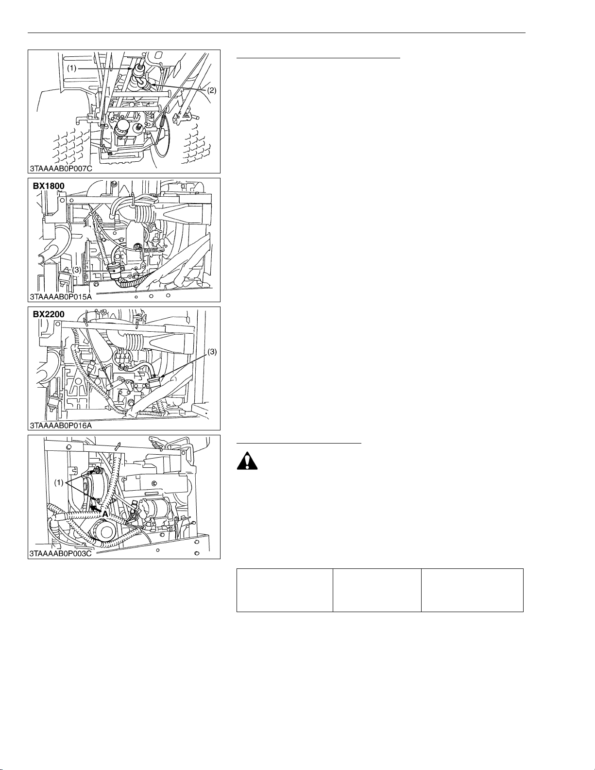
Checking Fuel Lines and Fuel Filter
1. The fuel line is made of rubber an d ages regardless of service
period.
2. After inspection, if the fuel line and clamps are found damaged or
deteriorated, replace them.
3. Check fuel filter, if it is clogged by debris or contaminated by
water, replace it.
• When the fuel line is disconnected for maintenance or
repair, plug both ends of the fuel line with a clean plug of
suitable size to prevent dust and dirt from entering.
Particular care must be taken not to admit dust a nd dirt into
the fuel system. Entrance of dust and dirt causes
malfunction of the fuel pump.
• If the fuel line is removed, be sure to properly bleed the fuel
system (see page G-25).
(1) Fuel Pump
(2) Fuel Filter
(3) Fuel Filter
W1017546
Checking Fan Belt Tension
CAUTION
• Be sure to stop engine before checking belt tension.
1. Stop the engine and remove the key.
2. Apply moderate thumb pressure to belt between pulleys.
3. If tension is incorrect, loosen the alternator mounting bolts and
using a lever placed between the alternator and the engine block,
pull the alternator out until the deflection of the be lt falls within
acceptable limits.
4. Replace fan belt if it is damaged.
A deflection of between 7
Fan belt tension Factory spec .
(1) Mounting Bolt A : Check the belt tension
to 9 mm (0.28 to 0.34 in.)
when the belt is pressed
in the middle of the span.
W1017708
G-18
 Loading...