

Kubuta B1830, B2230, B2530, B3030 Workshop Manual

WORKSHOP MANUAL
KiSC issued 05, 2012 A
TRACTOR
B1830,B2230,B2530,B3030

TO THE READER
KiSC issued 05, 2012 A
This Workshop Manual tells the servicing personnel about the mechanism, servicing and
maintenance of the B1830, B2230, B2530 and B3030. It contains 4 parts: "Information", "General",
"Mechanism" and "Servicing".
Information
This section primarily contains information below.
• Safety First
• Safety Decal
• Specification
• Dimension
General
This section primarily contains information below.
• Engine Identification
• Model Identification
• General Precautions
• Maintenance Check List
• Check and Maintenance
• Special Tools
Mechanism
This section contains information on the structure and the function of the unit. Before you continue
with the subsequent sections, make sure that you read this section.
Refer to the latest version of Workshop Manual (Code No. 9Y021-01870 / 9Y021-18200) for the
diesel engine / tractor mechanism that this workshop manual does not include.
Servicing
This section primarily contains information below.
• Troubleshooting
• Servicing Specifications
• Tightening Torques
• Checking, Disassembling and Servicing
All illustrations, photographs and specifications contained in this manual are of the newest
information available at the time of publication.
KUBOTA reserves the right to change all information at any time without notice.
Since this manual includes many models, information or illustrations and photographs can show
more than one model.
January, 2007
© KUBOTA Corporation 2007

I INFORMATION
KiSC issued 05, 2012 A

INFORMATION
KiSC issued 05, 2012 A
CONTENTS
1. SAFETY FIRST .............................................................................................................................. I-1
2. SAFETY DECALS .......................................................................................................................... I-4
[1] WITHOUT OPC ........................................................................................................................ I-4
[2] WITH OPC.............................................................................................................................. I-10
3. SPECIFICATIONS........................................................................................................................ I-13
4. TRAVELING SPEEDS.................................................................................................................. I-16
5. DIMENSIONS ............................................................................................................................... I-18
B1830,B2230,B2530,B3030, WSM
SAFETY FIRST
DANGER
WARNING
CAUTION
IMPORTANT
NOTE
KiSC issued 05, 2012 A
INFORMATION
1. SAFETY FIRST
• This symbol, the industry's "Safety Alert Symbol", is used throughout this manual and on labels on the
machine itself to warn of the possibility of personal injury. Read these instructions carefully.
• It is essential that you read the instructions and safety regulations before you attempt to repair or use
this unit.
• Indicates an imminently hazardous situation which, if not avoided, will result in death or serious injury.
• Indicates a potentially hazardous situation which, if not avoided, could result in death or serious injury.
• Indicates a potentially hazardous situation which, if not avoided, may result in minor or moderate
injury.
• Indicates that equipment or property damage could result if instructions are not followed.
• Gives helpful information.
WSM000001INI0001US1
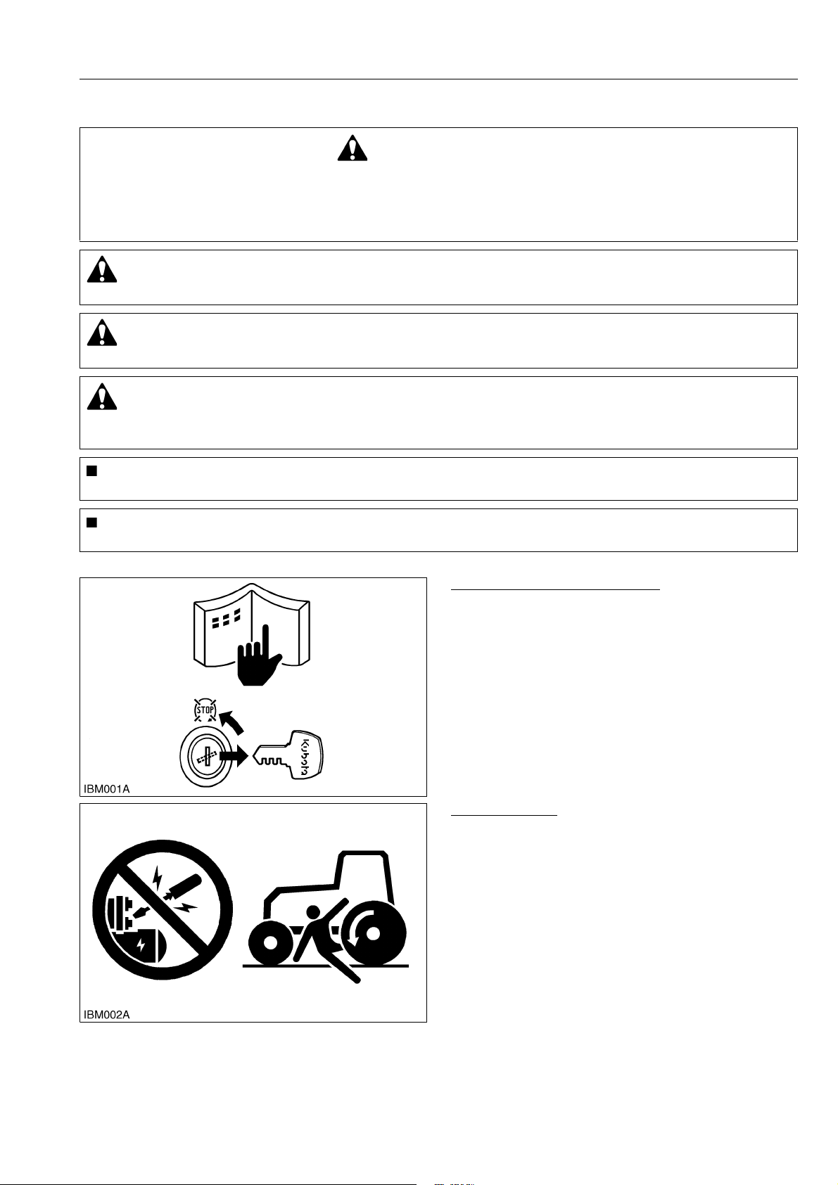
BEFORE YOU START SERVICE
• Read all instructions and safety instructions in this
manual and on your machine safety decals.
• Clean the work area and machine.
• Park the machine on a stable and level ground, and
set the parking brake.
• Lower the implement to the ground.
• Stop the engine, then remove the key.
• Disconnect the battery negative cable.
• Hang a "DO NOT OPERATE" tag in the operator
station.
WSM000001INI0010US1
START SAFELY
• Do not do the procedures below when you start the
engine.
– short across starter terminals
– bypass the safety start switch
• Do not alter or remove any part of machine safety
system.
• Before you start the engine, make sure that all shift
levers are in neutral positions or in disengaged
positions.
• Do not start the engine when you stay on the ground.
Start the engine only from operator's seat.
WSM000001INI0015US0
I-1
B1830,B2230,B2530,B3030, WSM
KiSC issued 05, 2012 A
INFORMATION
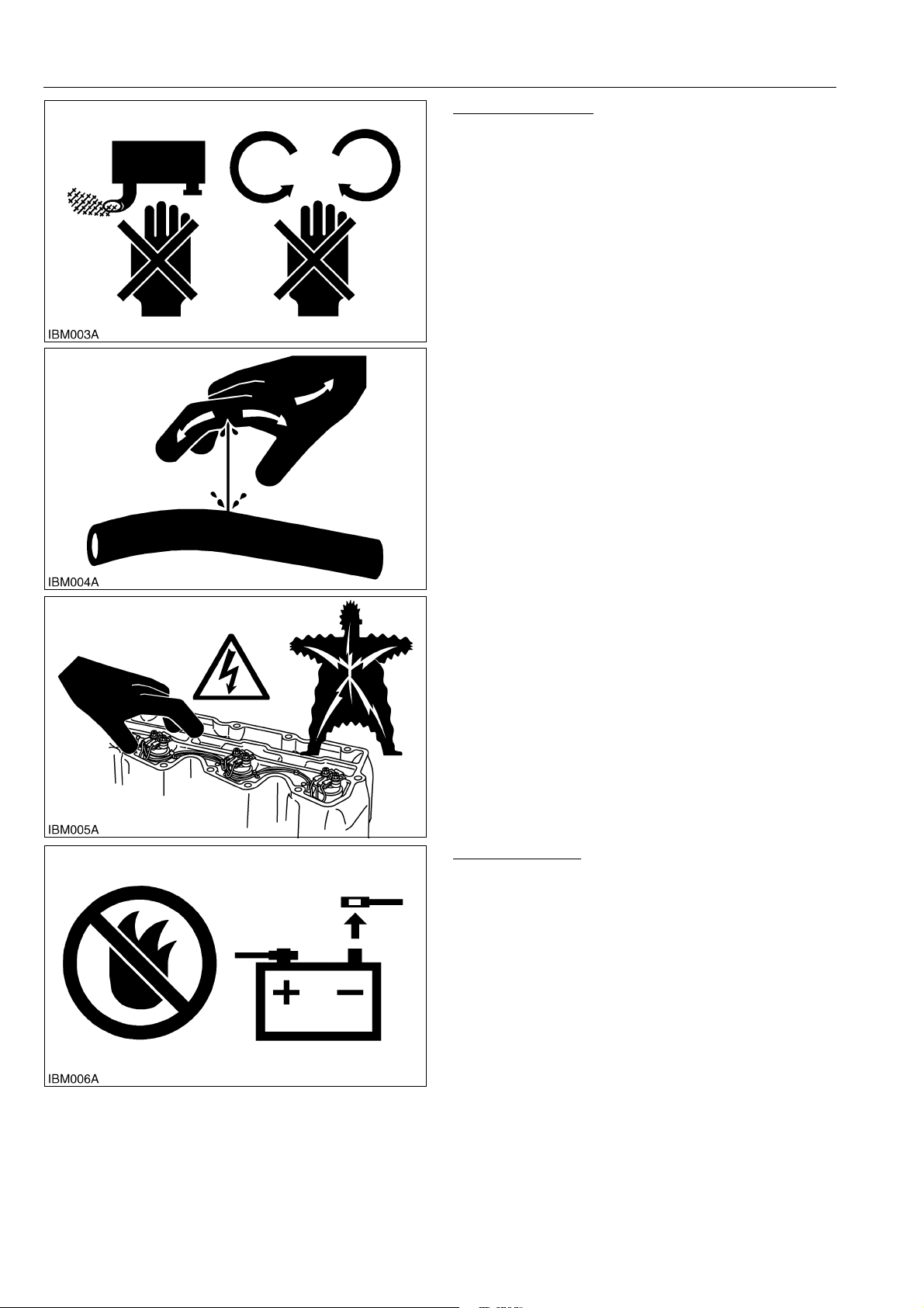
OPERATE SAFELY
• Do not use the machine after you consume alcohol
or medication or when you are tired.
• Put on applicable clothing and safety equipment.
• Use applicable tools only. Do not use alternative
tools or parts.
• When 2 or more persons do servicing, make sure
that you do it safely.
• Do not operate below the machine that only a jack
holds. Always use a safety stand to hold the
machine.
• Do not touch the hot parts or parts that turn when the
engine operates.
• Do not remove the radiator cap when the engine
operates, or immediately after it stops. If not, hot
water can spout out from the radiator. Only remove
the radiator cap when it is at a sufficiently low
temperature to touch with bare hands. Slowly loosen
the cap to release the pressure before you remove it
fully.
• Released fluid (fuel or hydraulic oil) under pressure
can cause damage to the skin and cause serious
injury. Release the pressure before you disconnect
hydraulic or fuel lines. Tighten all connections before
you apply the pressure.
• Do not open a fuel system under high pressure.
The fluid under high pressure that stays in fuel lines
can cause serious injury. Do not disconnect or repair
the fuel lines, sensors, or any other components
between the fuel pump and injectors on engines with
a common rail fuel system under high pressure.
• Put on an applicable ear protective device (earmuffs
or earplugs) to prevent injury against loud noises.
• Be careful about electric shock. The engine
generates a high voltage of more than DC100 V in
the ECU and is applied to the injector.
WSM000001INI0012US1
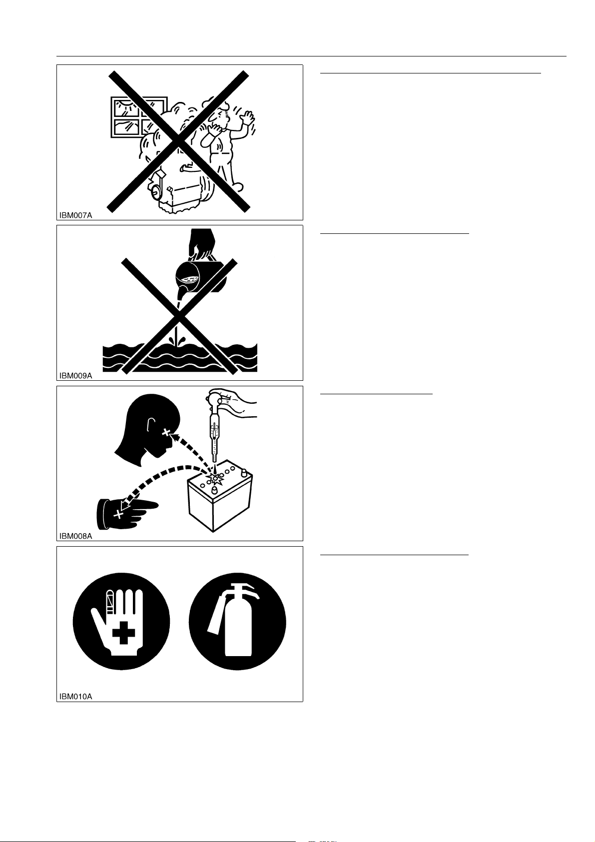
PREVENT A FIRE
• Fuel is very flammable and explosive under some
conditions. Do not smoke or let flames or sparks in
your work area.
• To prevent sparks from an accidental short circuit,
always disconnect the battery negative cable first
and connect it last.
• The battery gas can cause an explosion. Keep the
sparks and open flame away from the top of battery,
especially when you charge the battery.
• Make sure that you do not spill fuel on the engine.
WSM000001INI0005US1
I-2
B1830,B2230,B2530,B3030, WSM
KiSC issued 05, 2012 A
INFORMATION
KEEP A GOOD AIRFLOW IN THE WORK AREA
• If the engine is in operation, make sure that the area
has good airflow. Do not operate the engine in a
closed area. The exhaust gas contains poisonous
carbon monoxide.
WSM000001INI0006US1
DISCARD FLUIDS CORRECTLY
• Do not discard fluids on the ground, down the drain,
into a stream, pond, or lake. Obey related
environmental protection regulations when you
discard oil, fuel, coolant, electrolyte and other
dangerous waste.
WSM000001INI0007US1
PREVENT ACID BURNS
• Keep electrolyte away from your eyes, hands and
clothing. Sulfuric acid in battery electrolyte is
poisonous and it can burn your skin and clothing and
cause blindness. If you spill electrolyte on yourself,
clean yourself with water, and get medical aid
immediately.
WSM000001INI0008US1
PREPARE FOR EMERGENCIES
• Keep a first aid kit and fire extinguisher ready at all
times.
• Keep the emergency contact telephone numbers
near your telephone at all times.
WSM000001INI0009US1
I-3
B1830,B2230,B2530,B3030, WSM
KiSC issued 05, 2012 A
INFORMATION
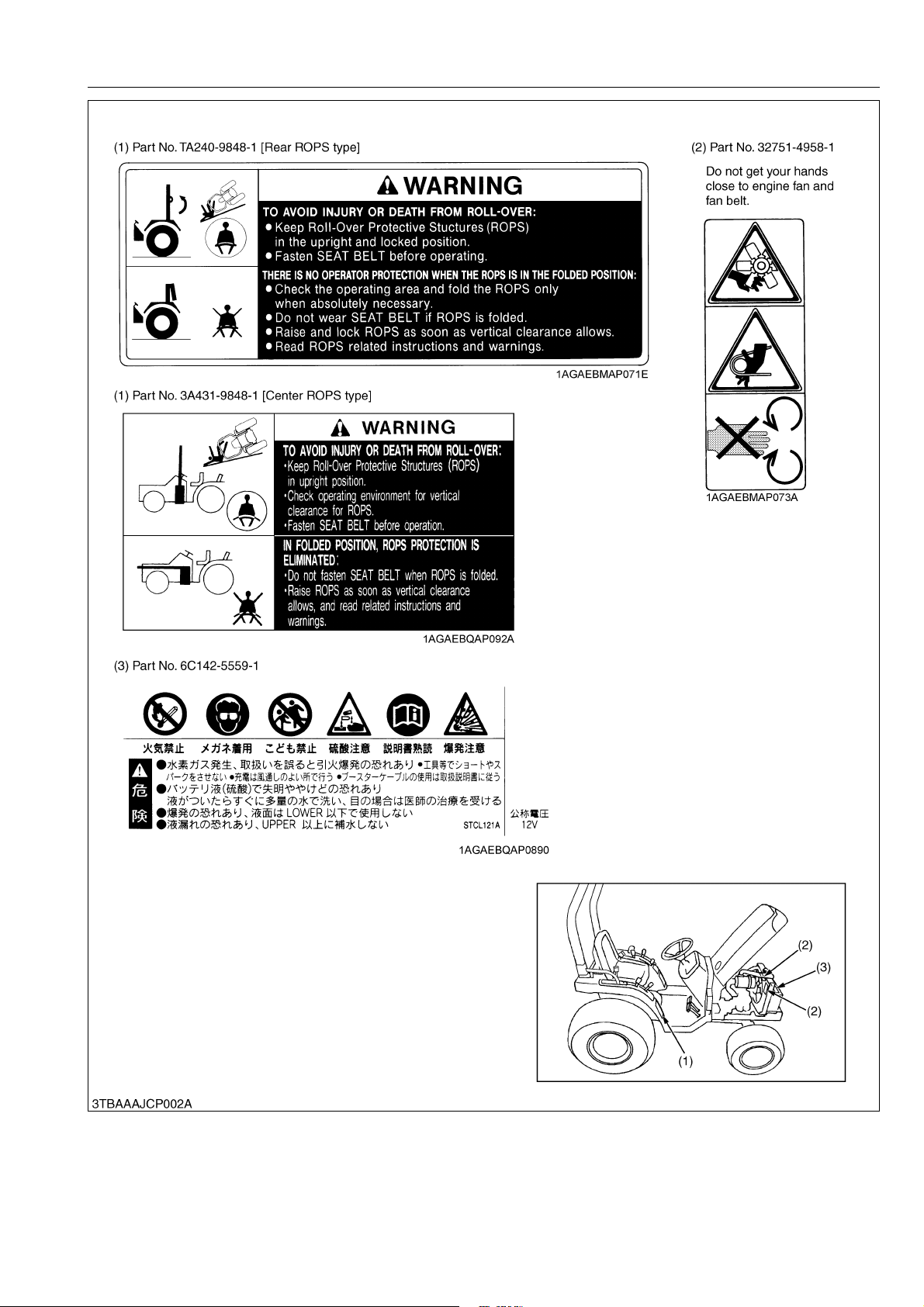
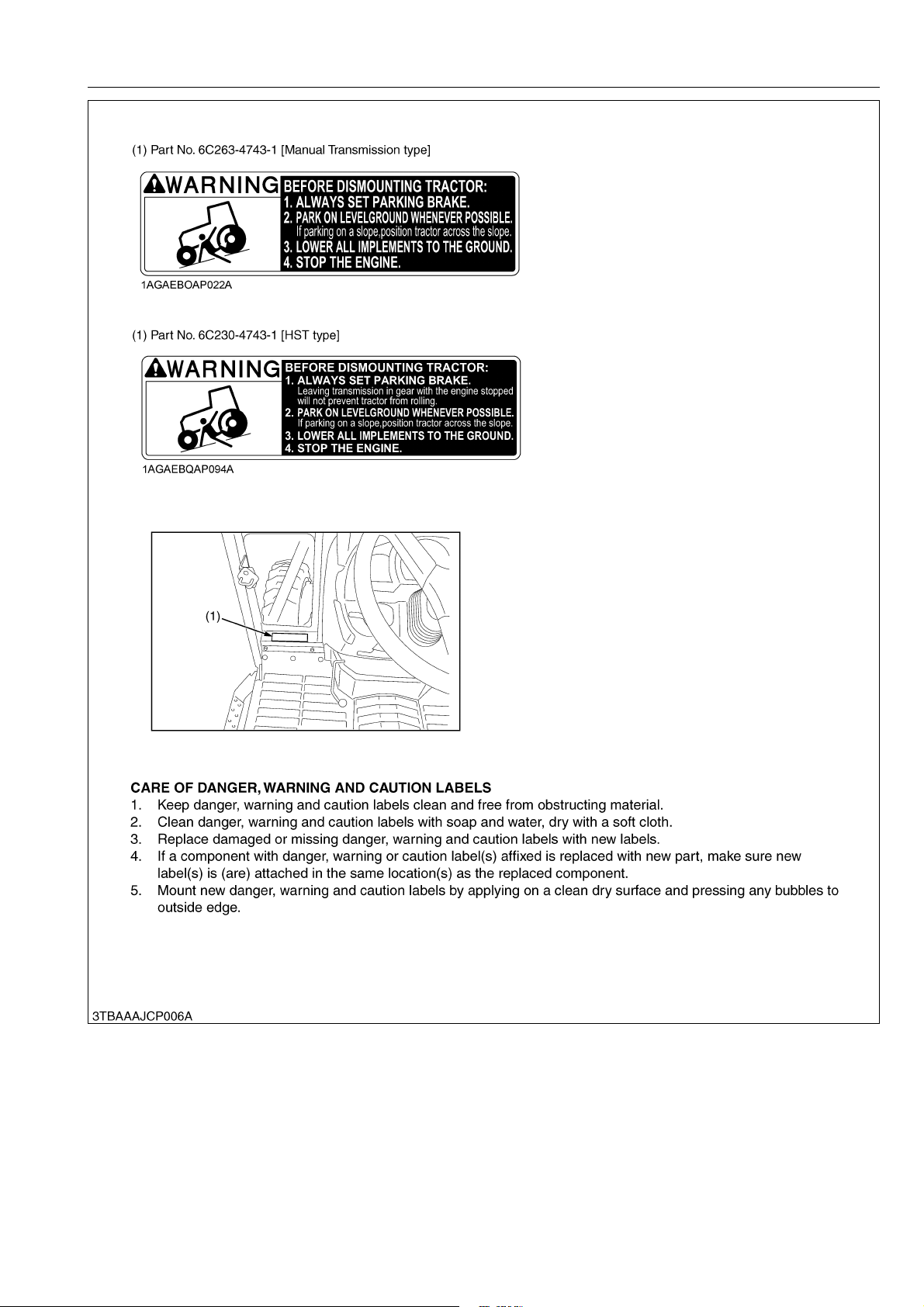
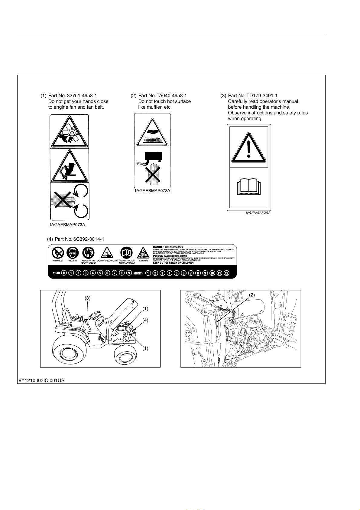
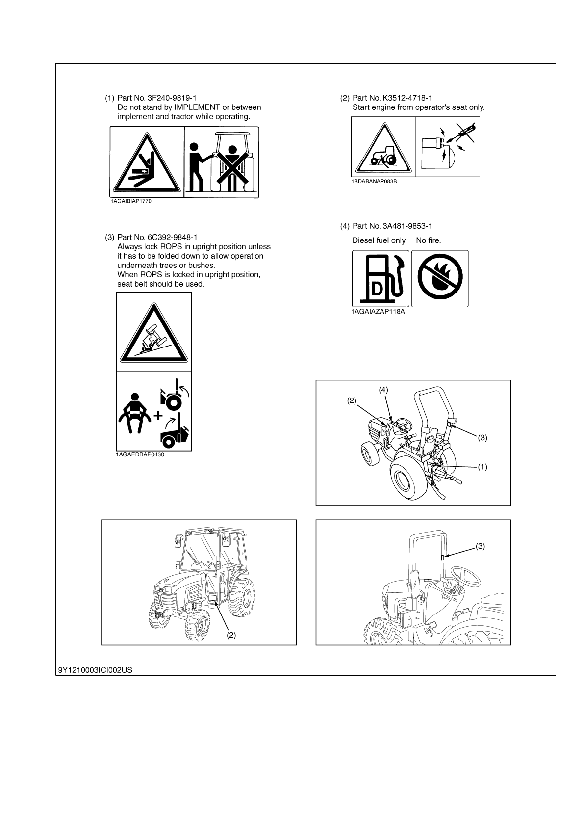
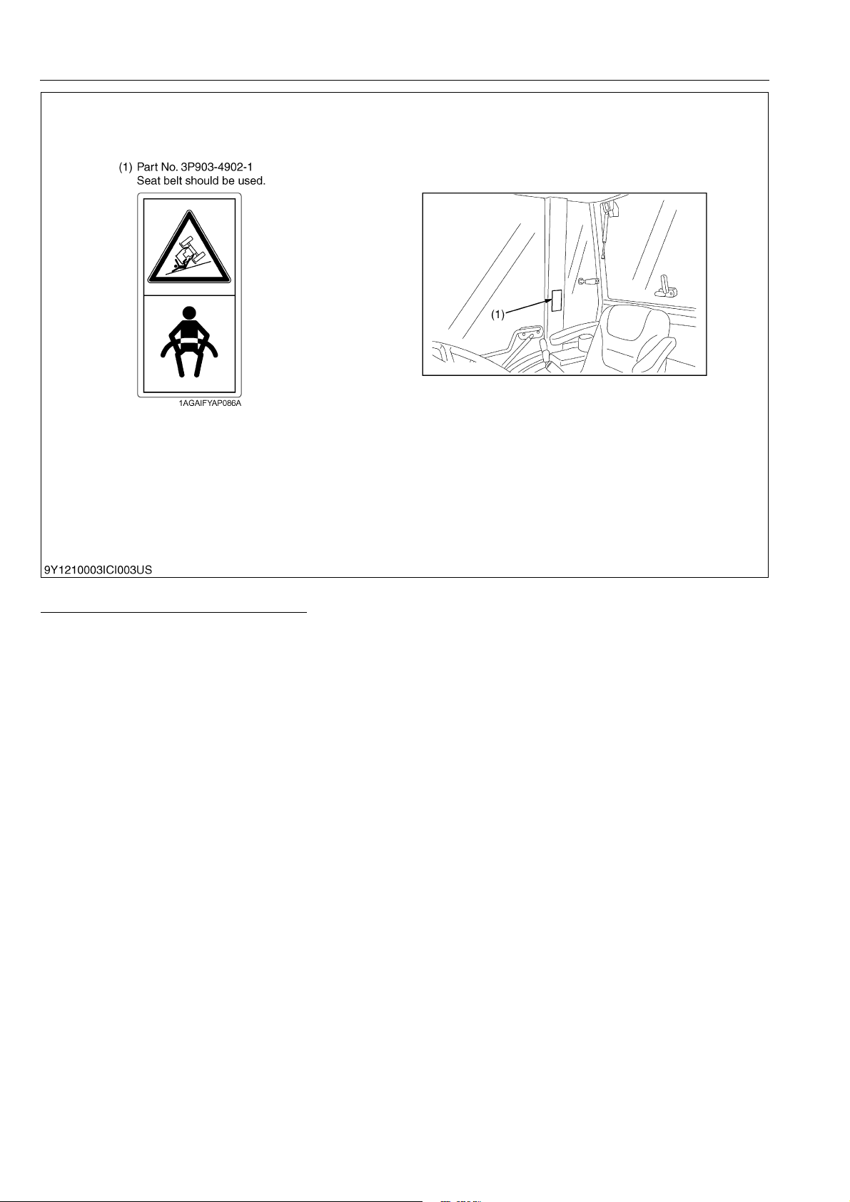
2. SAFETY DECALS
[1] WITHOUT OPC
The following safety decals (pictorial safety labels) are installed on the machine. If a decal becomes
damaged, illegible or is not on the machine, replace it. The decal part number is listed in the parts list.
WSM000001INI0014US0
ROPS and CABIN
9Y1210003INI0001US0
I-4
B1830,B2230,B2530,B3030, WSM
KiSC issued 05, 2012 A
INFORMATION
9Y1210003INI0002US0
I-5
B1830,B2230,B2530,B3030, WSM
KiSC issued 05, 2012 A
INFORMATION
9Y1210003INI0003US0
I-6
B1830,B2230,B2530,B3030, WSM
KiSC issued 05, 2012 A
INFORMATION
9Y1210003INI0004US0
I-7
B1830,B2230,B2530,B3030, WSM
KiSC issued 05, 2012 A
INFORMATION
CABIN
Careful operation is your best insurance against an accident.
Read and understand carefully this section of the separately issued operator's manual before operating the
tractor.
9Y1210003INI0005US0
I-8
B1830,B2230,B2530,B3030, WSM
KiSC issued 05, 2012 A
INFORMATION
9Y1210003INI0006US0
I-9
B1830,B2230,B2530,B3030, WSM
KiSC issued 05, 2012 A
INFORMATION
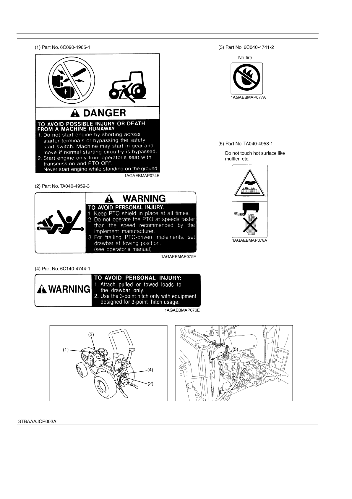
[2] WITH OPC
The following safety decals (pictorial safety labels) are installed on the machine. If a decal becomes
damaged, illegible or is not on the machine, replace it. The decal part number is listed in the parts list.
WSM000001INI0014US0
9Y1210003INI0007US0
I-10
B1830,B2230,B2530,B3030, WSM
KiSC issued 05, 2012 A
INFORMATION
9Y1210003INI0008US0
I-11
B1830,B2230,B2530,B3030, WSM
KiSC issued 05, 2012 A
INFORMATION
9Y1210003INI0009US0
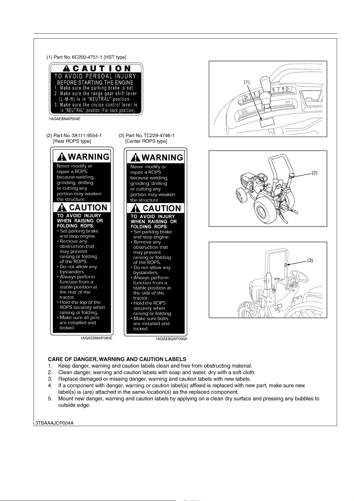
CARE OF PICTORIAL SAFETY LABELS
1. Keep pictorial safety labels clean and free from obstructing material.
2. Clean pictorial safety labels with soap and water, dry with a soft cloth.
3. Replace damaged or missing pictorial safety labels with new labels.
4. If a component with pictorial safety label(s) affixed is replaced with new part, make sure new label(s) is (are)
attached in the same location(s) as the replace component.
5. Mount new pictorial safety labels by applying on a clean dry surface and pressing any bubbles to outside edge.
9Y1210003INI0010US0
I-12

B1830,B2230,B2530,B3030, WSM
KiSC issued 05, 2012 A
INFORMATION
3. SPECIFICATIONS
[HST Model]
Model B2230 B2530 B3030
PTO power 12.5 kW (17.0 PS)* 14.0 kW (19.0 PS)* 16.9 kW (23.0 PS)*
Maker KUBOTA
Model D1005-E2-D21-EU D1105-E2-D21-EU V1505-E2-D21-EU
Type E-TVCS, water-cooled, 4-cycle diesel
Number of cylinders 3 4
Engine
Capacities
Dimensions
Weight
Travelling
system
Hydraulic
system
Bore and stroke 76 × 73.6 mm (3.0 × 2.9 in.) 78 × 78.4 mm (3.1 × 3.1 in.) 78 × 78.4 mm (3.1 × 3.1 in.)
Total displacement 1001 cm
Engine gross power 16.2 kW (22.0 PS)* 18.4 kW (25.0 PS)* 22.1 kW (30.0 PS)*
Rated revolution 2700 min
Maximum torque
Battery 12 V, RC: 75 min, CCA: 430 A
Starting system Electric starting with cell starter 12 V, 1.4 kW
Lubricating system Forced lubrication by trochoidal pump
Cooling system Pressurized radiator, forced circulation with water pump
Fuel Diesel fuel No. 2-D [above −10 °C (14 °F)], Diesel fuel No. 1 [below −10 °C (14 °F)]
Fuel tank 28 L (7.4 U.S.gals, 6.2 Imp.gals)
Engine crankcase (with filter) 3.0 L (3.2 U.S.qts, 2.6 Imp.qts)
Engine coolant 5.2 L (5.5 U.S.qts, 4.6 Imp.qts)
Transmission case 17 L (4.5 U.S.gals, 3.7 Imp.gals)
Front axle case 3.7 L (3.9 U.S.qts, 3.3 Imp.qts)
Tire
Overall length
(with 3P)
Overall width (min. tread) 1105 mm (43.5 in.) 1095 mm (43.1 in.) 1365 mm (53.7 in.)
Overall height
Wheel base 1500 mm (59.1 in.) 1666 mm (65.6 in.)
Minimum ground clearance 240 mm (9.5 in.) 270 mm (10.6 in.) 315 mm (12.4 in.)
Tread
ROPS 745 kg (1643 lbs) 750 kg (1654 lbs) 840 kg (1852 lbs)
CABIN 955 kg (2106 lbs) 960 kg (2117 lbs) 1035 kg (2282 lbs)
Clutch N/A
Steering Hydrostatic power steering
Transmission Main-hydrostatic transmission, 3 range gear shift (3 forward and 3 reverse)
Brake Wet disk type
Min. turning radius
(with brake)
Differential Bevel gear
Hydraulic control system Position control
Pump capacity
Three point hitch SAE Category 1
Max. lift force
Front 6-12B 6-12 6.00-2 7.00-12
Rear 8-16 9.5-16 9.5-18 10.5-18
ROPS 2735 mm (107.7 in.) 2900 mm (114.2 in.)
CABIN 2835 mm (111.6 in.) 3010 mm (118.6 in.)
ROPS 2260 mm (89.0 in.) 2290 mm (90.2 in.) 2320 mm (91.3 in.)
CABIN 2060 mm (81.1 in.) 2090 mm (82.3 in.) 2125 mm (83.7 in.)
Front 835 mm (32.9 in.) 935 mm (36.8 in.)
Rear
At lift points 970 kg (2139 lbs)
24 in. behind
lift points
3
(61.1 cu.in.) 1123 cm3 (68.5 cu.in.) 1498 cm3 (91.4 cu.in.)
-1
(rpm) 2600 min-1 (rpm)
62 N·m
(6.3 kgf·m, 13.9 lbf·ft)
Farm Turf Farm Turf
855 to 1075 mm
(33.7 to 42.3 in.)
3P: 20.5 L/min (5.4 gals/min)
Power steering: 15.4 L/min (1.4 gals/min)
(7.3 kgf·m, 16.2 lbf·ft)
72 N·m
22 ×
8.50-12
31 ×
13.5-15
850 to 1095 mm
(33.5 to 43.1 in.)
2.1 m (6.9 feet)
760 kg (1676 lbs)
24 ×
8.5-12
315/75D
-15
92 N·m
(9.4 kgf·m, 20.7 lbf·ft)
31 L
(8.1 U.S.gals, 6.8 Imp.gals)
4.1 L
(4.3 U.S.qts, 3.6 Imp.qts)
4.7 L
(5.0 U.S.qts, 4.1 Imp.qts)
7-12 24 × 8.5-12
12.4-16 13.6-16
1050 mm (41.3 in.)
3P: 19.7 L/min
(5.2 gals/min)
Power steering:
14.8 L/min (3.9 gals/min)
I-13

B1830,B2230,B2530,B3030, WSM
NOTE
KiSC issued 05, 2012 A
Model B2230 B2530 B3030
Rear
PTO system
Mid
PTO shaft SAE 1-3/8, 6 splines
Revolution 1 speed (540 min
PTO shaft U.S.A. No.5 (KUBOTA 10-tooth) involute spline
Revolution 1 speed (2500 min
• * Manufacture's estimate
The company reserves the right to change the specifications without notice.
-1
(rpm) at 2592 engine min-1 (rpm))
-1
(rpm) at 2600 engine min-1 (rpm))
INFORMATION
I-14

B1830,B2230,B2530,B3030, WSM
NOTE
KiSC issued 05, 2012 A
INFORMATION
[Manual Transmission Model]
Model B1830 B2230 B2530
PTO power 11.0 kW (15.0 PS)* 13.2 kW (18.0 PS)* 14.7 kW (20.0 PS)*
Maker KUBOTA
Model D905-E2-D21-EU D1005-E2-D21-EU D1105-E2-D21-EU
Type E-TVCS, water-cooled, 4-cycle diesel
Number of cylinders 3
Engine
Capacities
Dimensions
Weight
Travelling
system
Hydraulic
system
PTO system
Bore and stroke 72 × 78.4 mm (2.8 × 3.1 in.) 76 × 73.6 mm (3.0 × 2.9 in.) 78 × 78.4 mm (3.1 × 3.1 in.)
Total displacement 898 cm
Engine gross power 13.2 kW (18.0 PS)* 16.2 kW (22.0 PS)* 18.4 kW (25.0 PS)*
Rated revolution 2700 min
Maximum torque
Battery 12 V, RC: 75 min, CCA: 430 A
Starting system Electric starting with cell starter 12 V, 1.4 kW
Lubricating system Forced lubrication by trochoidal pump
Cooling system Pressurized radiator, forced circulation with water pump
Fuel Diesel fuel No. 2-D [above −10 °C (14 °F)], Diesel fuel No. 1 [below −10 °C (14 °F)]
Fuel tank 28 L (7.4 U.S.gals, 6.2 Imp.gals)
Engine crankcase (with filter) 3.0 L (3.2 U.S.qts, 2.6 Imp.qts)
Engine
coolant
ROPS 4.5 L (4.7 U.S.qts, 4.0 Imp.qts)
CABIN – 5.2 L (5.5 U.S.qts, 4.6 Imp.qts)
Transmission case
Front axle case 3.7 L (3.9 U.S.qts, 3.3 Imp.qts)
Tire
Front 6-12B 6-12 6.00-12 7.00-12 22 × 8.50-12 24 × 8.5-12
Rear 8-16 9.5-16 9.5-18 10.5-18 31 × 13.5-15 315/75D-15
Overall length
(with 3P)
ROPS 2735 mm (107.7 in.)
CABIN – 2835 mm (111.6 in.)
Overall width (min-tread) 1025 mm (40.4 in.) 1105 mm (43.5 in.) 1095 mm (43.1 in.)
Overall height
ROPS 2240 mm (88.2 in.) 2260 mm (89.0 in.) 2290 mm (90.2 in.)
CABIN – 2060 mm (81.1 in.) 2090 mm (82.3 in.)
Wheel base 1500 mm (59.1 in.)
Minimum ground clearance 220 mm (8.7 in.) 240 mm (9.5 in.) 270 mm (10.6 in.)
Front 835 mm (32.9 in.)
Tread
Rear
ROPS 705 kg (1555 lbs) 720 kg (1588 lbs) 725 kg (1599 lbs)
CABIN – 930 kg (2051 lbs) 935 kg (2062 lbs)
Clutch Dry single plate
Steering Hydrostatic power steering
Transmission Gear shift (9 forward and 9 reverse)
Brake Wet disk type
Min. turning radius
(with brake)
Differential Bevel gear
Hydraulic control system Position control
Pump capacity 3P: 20.5 L/min (5.4 gals/min) / Power steering: 15.4 L/min (4.1 gals/min)
Three point hitch SAE Category 1
At lift points 970 kg (2139 lbs)
Max. lift force
24 in. behind
lift points
Rear
Mid
PTO shaft SAE 1-3/8, 6 splines
Revolution 1 speed (540 min
PTO shaft U.S.A. No.5 (KUBOTA 10-tooth) involute spline
Revolution 1 speed (2500 min
3
(54.8 cu.in.) 1001 cm3 (61.1 cu.in.) 1123 cm3 (68.5 cu.in.)
-1
(rpm)
54 N·m
(5.5 kgf·m, 12.1 lbf·ft)
62 N·m
(6.3 kgf·m, 13.9 lbf·ft)
(7.3 kgf·m, 16.2 lbf·ft)
Bi-Speed: 16.5 L (4.4 U.S.gals, 3.6 Imp.gals),
No Bi-Speed: 15 L (4.0 U.S.gals, 3.3 Imp.gals)
Farm Turf
800 to 970 mm
(31.5 to 38.2 in.)
855 to 1075 mm
(33.7 to 42.3 in.)
850 to 1095 mm
(33.5 to 43.1 in.)
2.1 m (6.9 feet)
760 kg (1676 lbs)
-1
(rpm) at 2592 engine min-1 (rpm))
-1
(rpm) at 2600 engine min-1 (rpm))
72 N·m
• * Manufacture's estimate
The company reserves the right to change the specifications without notice.
9Y1210003INI0011US0
I-15

B1830,B2230,B2530,B3030, WSM
KiSC issued 05, 2012 A
4. TRAVELING SPEEDS
[HST Model]
Model B2230 / B2530
Tire size (Rear)
Forward
Reverse
Range gear shift
lever
Low
Middle
High
Max. Speed
(at 2850 engine
rpm)
Low
Middle
High
Max. Speed
(at 2850 engine
rpm)
8-16
Farm
0 to 3.95
(0 to 2.5)
0 to 7.35
(0 to 4.6)
0 to 19.05
(0 to 11.8)
20.10
(12.5)
0 to 3.16
(0 to 2.0)
0 to 5.88
(0 to 3.7)
15.
0 to
(0 to 9.5)
24
16.08
(10.0)
9.5-16
Farm
0 to 4.18
(0 to 2.6)
0 to 7.77
(0 to 4.8)
0 to 20.14
(0 to 12.5)
21.26
(13.2)
0 to 3.34
(0 to 2.1)
0 to 6.21
(0 to 3.9)
0 to 16.11
(0 to 10.0)
17.01
(10.6)
9.5-18
Farm
0 to 4.49
(0 to 2.8)
0 to 8.34
(0 to 5.2)
0 to 21.63
(0 to 13.4)
22.83
(14.2)
0 to 3.59
(0 to 2.2)
0 to 6.68
(0 to 4.2)
0 to 17.31
(0 to 10.8)
18.27
(11.4)
10.5-18
Farm
km/h
(mile/h)
0 to 4.69
(0 to 2.9)
0 to 8.73
(0 to 5.4)
0 to 22.63
(0 to 14.1)
23.88
(14.8)
0 to 3.75
(0 to 2.3)
0 to 6.98
(0 to 4.3)
0 to 18.10
(0 to 11.2)
19.11
(11.9)
31 × 13.5-15
Turf
0 to 3.87
(0 to 2.4)
0 to 7.19
(0 to 4.5)
0 to 18.65
(0 to 11.6)
19.69
(12.2)
0 to 3.09
(0 to 1.9)
0 to 5.75
(0 to 3.6)
0 to 14.92
(0 to 9.3)
15.75
(9.8)
INFORMATION
315 /75D -15
Turf
0 to 4.22
(0 to 2.6)
0 to 7.85
(0 to 4.9)
0 to 20.34
(0 to 12.6)
21.47
(13.3)
0 to 3.37
(0 to 2.1)
0 to 6.28
(0 to 3.9)
0 to 16.27
(0 to 10.1)
17.18
(10.7)
Model B3030
Tire size (Rear) 12.4-16 Farm 13.6-16 Turf
Range gear shift lever km/h (mile/h)
Low 0 to 4.59 (0 to 2.9) 0 to 4.73 (0 to 2.9)
Middle 0 to 8.54 (0 to 5.3) 0 to 8.79 (0 to 5.5)
Forward
Reverse
The company reserves the right to change the specifications without notice.
High 0 to 22.15 (0 to 13.8) 0 to 22.80 (0 to 14.2)
Max. Speed
(at 2750 engine rpm)
Low 0 to 3.67 (0 to 2.3) 0 to 3.78 (0 to 2.3)
Middle 0 to 6.83 (0 to 4.2) 0 to 7.03 (0 to 4.4)
High 0 to 17.72 (0 to 11.0) 0 to 18.24 (0 to 11.3)
Max. Speed
(at 2750 engine rpm)
23.43 (14.6) 24.11 (15.0)
18.74 (11.6) 19.29 (12.0)
I-16

B1830,B2230,B2530,B3030, WSM
KiSC issued 05, 2012 A
[Manual Transmission Model]
Model B1830 / B2230 / B2530
Tire size (Rear)
Range gear
shift lever
1
Low
2 1.65 (1.0) 1.75 (1.1) 1.88 (1.2) 1.96 (1.2) 1.62 (1.0) 1.77 (1.1)
3 2.57 (1.6) 2.71 (1.7) 2.91 (1.8) 3.05 (1.9) 2.51 (1.6) 2.74 (1.7)
4
Middle
5 3.07 (1.9) 3.25 (2.0) 3.49 (2.2) 3.65 (2.3) 3.01 (1.9) 3.28 (2.0)
6 4.77 (3.0) 5.05 (3.1) 5.42 (3.4) 5.67 (3.5) 4.67 (2.9) 5.10 (3.2)
Forward
7
8
High
9
Max. Speed
(at 2850
engine rpm)
1
Low
2 1.67 (1.0) 1.77 (1.1) 1.90 (1.2) 1.99 (1.2) 1.64 (1.0) 1.78 (1.1)
3 2.59 (1.6) 2.74 (1.7) 2.95 (1.8) 3.08 (1.9) 2.54 (1.6) 2.77 (1.7)
4
Middle
5 3.11 (1.9) 3.29 (2.0) 3.53 (2.2) 3.69 (2.3) 3.04 (1.9) 3.32 (2.1)
6 4.82 (3.0) 5.10 (3.2) 5.48 (3.4) 5.73 (3.6) 4.72 (2.9) 5.15 (3.2)
Reverse
7
8
High
9
Max. Speed
(at 2850
engine rpm)
INFORMATION
8-16
Farm
9.5-16
Farm
9.5-18
Turf
10.5-18
Farm
31 ×
13.5-15Turf
315
/75D-15Turf
km/h
(mile/h)
1.00 (0.6) 1.05 (0.7) 1.13 (0.7) 1.18 (0.7) 0.98 (0.6) 1.06 (0.7)
1.85 (1.1) 1.96 (1.2) 2.11 (1.3) 2.20 (1.4) 1.82 (1.1) 1.98 (1.2)
6.65 (4.1) 7.03 (4.4) 7.55 (4.7) 7.90 (4.9) 6.51 (4.0) 7.10 (4.4)
11.03
(6.9)
17.12
(10.6)
18.07
(11.2)
11.67
(7.3)
18.10
(11.2)
19.11
(11.9)
12.53
(7.8)
19.44
(12.1)
20.52
(12.8)
13.11
(8.1)
20.34
(12.6)
21.47
(13.3)
10.80 (6.7) 11.78 (7.3)
16.76 (10.4) 18.28 (11.4)
17.69 (11.0) 19.30 (12.0)
1.01 (0.6) 1.07 (0.7) 1.14 (0.7) 1.20 (0.7) 0.99 (0.6) 1.08 (0.7)
1.87 (1.2) 1.98 (1.2) 2.13 (1.3) 2.23 (1.4) 1.84 (1.1) 2.00 (1.2)
6.73 (4.2) 7.11 (4.4) 7.64 (4.7) 7.99 (5.0) 6.58 (4.1) 7.18 (4.5)
11.15
(6.9)
17.31
(10.8)
18.27
(11.4)
11.80
(7.3)
18.30
(11.4)
19.32
(12.0)
12.67
(7.9)
19.66
2.2)
(1
20.75
(12.9)
13.25
(8.2)
0.56
2
(12.8)
21.71
(13.5)
10.92 (6.8) 11.91 (7.4)
16.95 (10.5) 18.49 (11.5)
17.89 (11.1) 19.51 (12.1)
9Y1210003INI0012US0
I-17
B1830,B2230,B2530,B3030, WSM
KiSC issued 05, 2012 A
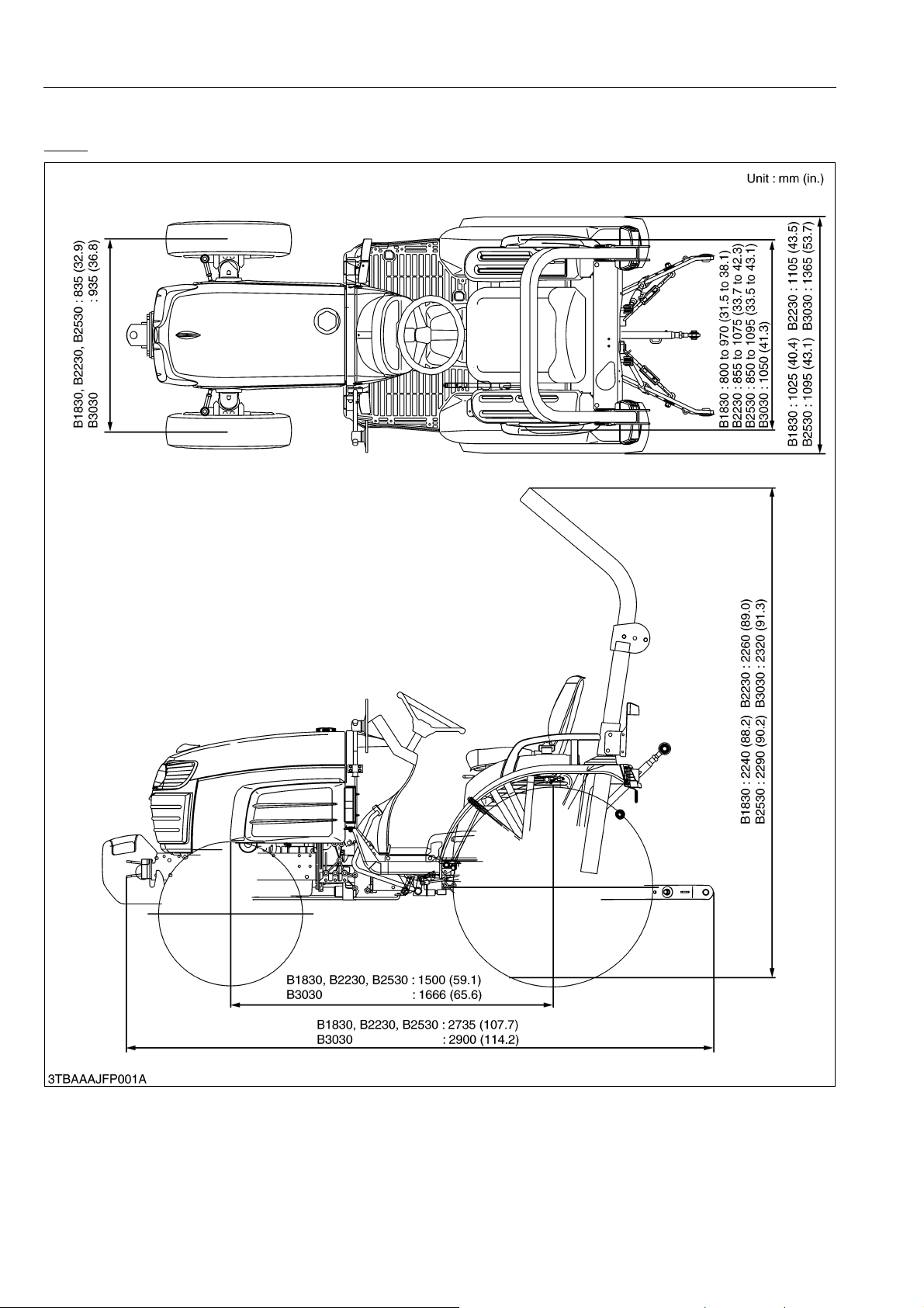
5. DIMENSIONS
ROPS
INFORMATION
9Y1210003INI0013US0
I-18
B1830,B2230,B2530,B3030, WSM
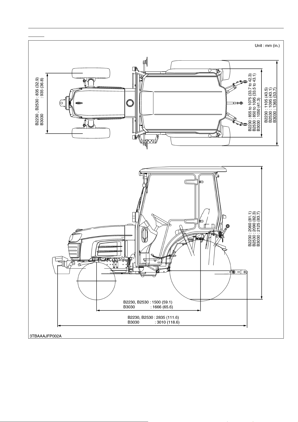
KiSC issued 05, 2012 A
CABIN
INFORMATION
9Y1210003INI0014US0
I-19

G GENERAL
KiSC issued 05, 2012 A

GENERAL
KiSC issued 05, 2012 A
CONTENTS
1. TRACTOR IDENTIFICATION ....................................................................................................... G-1
2. GENERAL PRECAUTIONS......................................................................................................... G-2
3. HANDLING PRECAUTIONS FOR ELECTRICAL PARTS AND WIRING .............................. G-3
[1] WIRING .................................................................................................................................. G-3
[2] BATTERY ............................................................................................................................... G-5
[3] FUSE ...................................................................................................................................... G-5
[4] CONNECTOR ........................................................................................................................ G-5
[5] HANDLING OF CIRCUIT TESTER ..................................................................................... G-6
[6] COLOR OF WIRING ..............................................................................................................G-7
4. LUBRICANTS, FUEL AND COOLANT......................................................................................... G-8
5. TIGHTENING TORQUES .......................................................................................................... G-10
[1] GENERAL USE SCREWS, BOLTS AND NUTS ............................................................. G-10
[2] STUD BOLTS ...................................................................................................................... G-10
6. MAINTENANCE CHECK LIST ................................................................................................... G-11
7. CHECK AND MAINTENANCE ................................................................................................... G-13
[1] DAILY CHECK...................................................................................................................... G-13
[2] CHECK POINTS OF INITIAL 50 HOURS ............................................................................ G-14
[3] CHECK POINTS OF EVERY 50 HOURS ............................................................................ G-18
[4] CHECK POINTS OF EVERY 100 HOURS .......................................................................... G-23
[5] CHECK POINTS OF EVERY 200 HOURS .......................................................................... G-30
[6] CHECK POINTS OF EVERY 300 HOURS .......................................................................... G-34
[7] CHECK POINTS OF EVERY 400 HOURS .......................................................................... G-36
[8] CHECK POINT OF EVERY 800 HOURS ............................................................................. G-38
[9] CHECK POINTS OF EVERY 1500 HOURS ........................................................................ G-39
[10]CHECK POINTS OF EVERY 1 YEAR.................................................................................. G-40
[11]CHECK POINTS OF EVERY 2 YEARS ............................................................................... G-42
[12]OTHERS............................................................................................................................... G-46
8. SPECIAL TOOLS ....................................................................................................................... G-54
[1] SPECIAL TOOLS FOR ENGINE .......................................................................................... G-54
[2] SPECIAL TOOLS FOR TRACTOR ...................................................................................... G-60
[3] SPECIAL TOOLS FOR CABIN............................................................................................. G-63
9. TIRES ......................................................................................................................................... G-66
G
[1] TIRE PRESSURE.................................................................................................................
[2] TREAD ................................................................................................................................. G-67
(1) Front Wheels .................................................................................................................. G-68
(2) Rear Wheels................................................................................................................... G-69
[3] TIRE LIQUID INJECTION AND BALLAST ........................................................................... G-71
10. IMPLEMENT LIMITATIONS ....................................................................................................... G-74
-66
B1830,B2230,B2530,B3030, WSM
KiSC issued 05, 2012 A
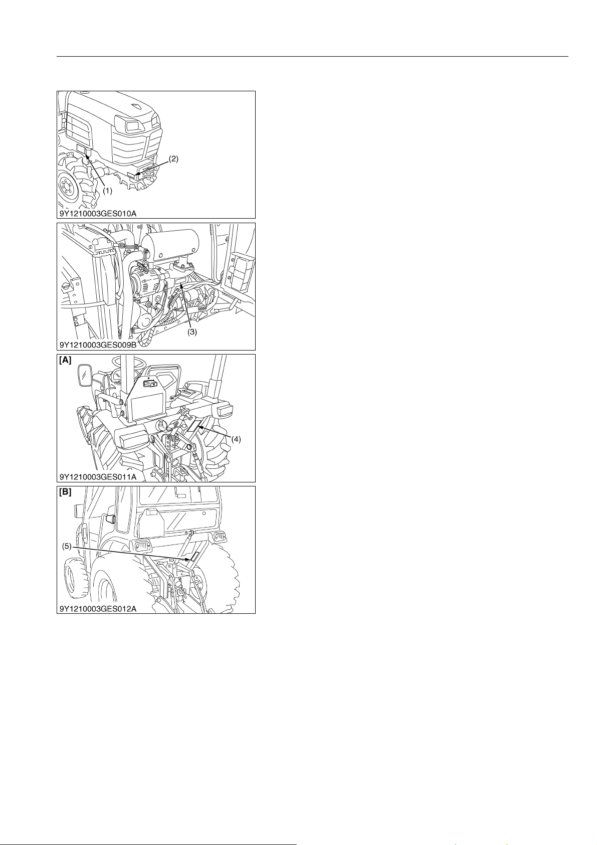
1. TRACTOR IDENTIFICATION
When contacting your local KUBOTA distributor, always specify
engine serial number, tractor serial number and hour meter reading.
(1) Tractor Identification Plate
(2) Tractor Serial Number
(3) Engine Serial Number
(4) ROPS Identification Plate
(ROPS Serial Number)
(5) CABIN Identification Plate
(CABIN Serial Number)
GENERAL
[A] ROPS
[B] CABIN
9Y1210003GEG0001US0
G-1
B1830,B2230,B2530,B3030, WSM
KiSC issued 05, 2012 A
2. GENERAL PRECAUTIONS
• When you disassemble, carefully put the parts in a clean area
to make it easy to find the parts. You must install the screws,
bolts and nuts in their initial position to prevent the reassembly
errors.
• When it is necessary to use special tools, use KUBOTA special
tools. Refer to the drawings when you make special tools that
you do not use frequently.
• Before you disassemble or repair machine, make sure that you
always disconnect the ground cable from the battery first.
• Remove oil and dirt from parts before you measure.
• Use only KUBOTA genuine parts for replacement to keep the
machine performance and to make sure of safety.
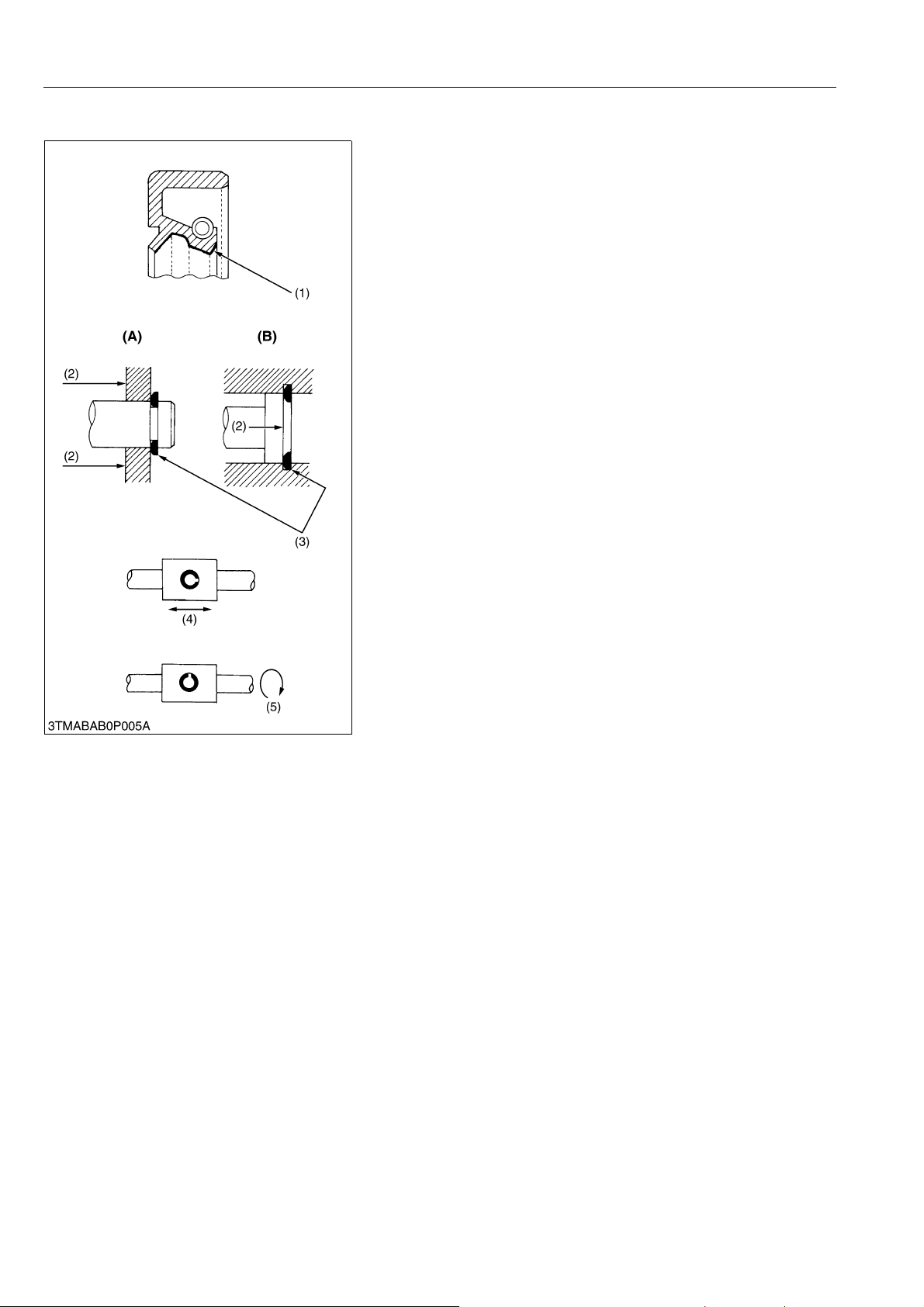
• You must replace the gaskets and O-rings when you assemble
again. Apply grease (1) to new O-rings or oil seals before you
assemble.
• When you assemble the external or internal snap rings, make
sure that the sharp edge (3) faces against the direction from
which force (2) is applied.
• When inserting spring pins, their splits must face the direction
from which a force is applied. See the figure left side.
• To prevent damage to the hydraulic system, use only specified
fluid or equivalent.
• Clean the parts before you measure them.
• Tighten the nipples to the specified torque. Too much torque
can cause damage to the hydraulic units or the nipples. Not
sufficient torque can cause oil leakage.
• When you use a new hose or pipe, tighten the nuts to the
specified torque. Then loosen (approx. by 45 °) and let them be
stable before you tighten to the specified torque (This is not
applied to the parts with seal tape).
• When you remove the two ends of a pipe, remove the lower end
first.
• Use two pliers in removal and installation. One to hold the stable
side, and the other to turn the side you remove to prevent twists.
• Make sure that the sleeves of flared connectors and taper s of
hoses are free of dust and scratches.
• After you tighten the nipples, clean the joint and apply the
maximum operation pressure 2 to 3 times to examine oil
leakage.
(1) Grease
(2) Force
(3) Sharp Edge
(4) Axial Force
(5) Rotating Movement
GENERAL
(A) External Snap Ring
(B) Internal Snap Ring
WSM000001GEG0106US1
G-2
B1830,B2230,B2530,B3030, WSM
IMPORTANT
KiSC issued 05, 2012 A
GENERAL
3. HANDLING PRECAUTIONS FOR ELECTRICAL PARTS AND WIRING
To ensure safety and prevent damage to the machine and
surrounding equipment, heed the following precautions in handling
electrical parts and wiring.
• Check electrical wiring for damage and loosened
connection every year. To this end, educate the customer
to do his or her own check and at the same time
recommend the dealer to perform periodic check for a fee.
• Do not attempt to modify or remodel any electrical parts
and wiring.
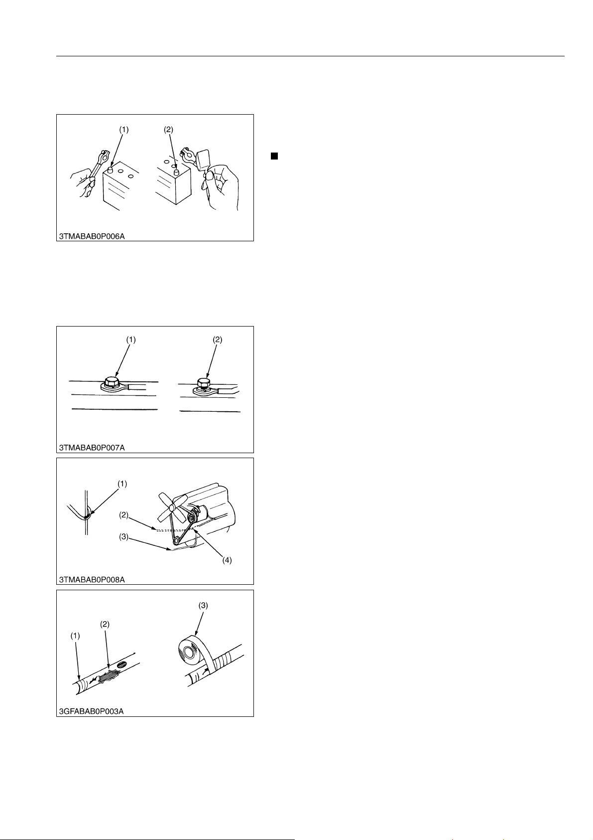
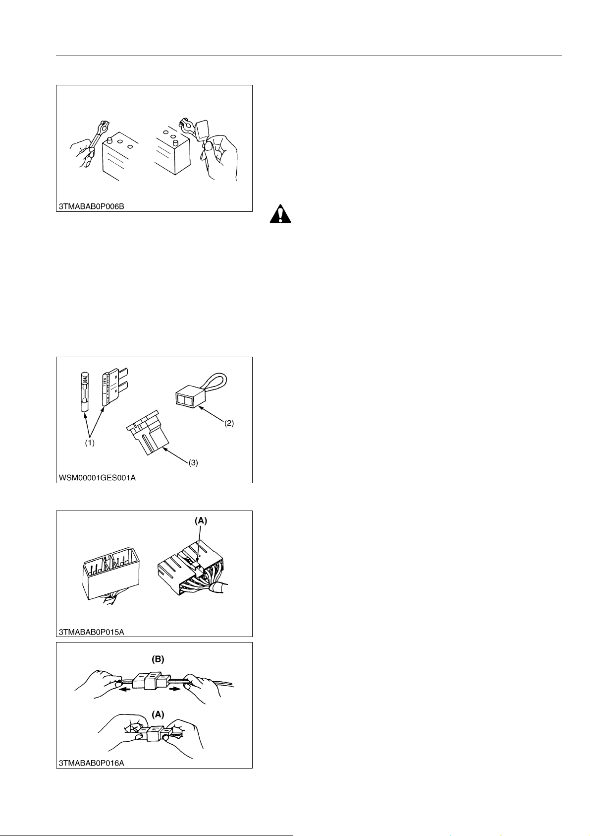
• When removing the battery cables, disconnect the negative
cable first. When installing the battery cables, connect the
positive cable first.
(1) Negative Terminal (2) Positive Terminal
WSM000001GEG0062US1
[1] WIRING
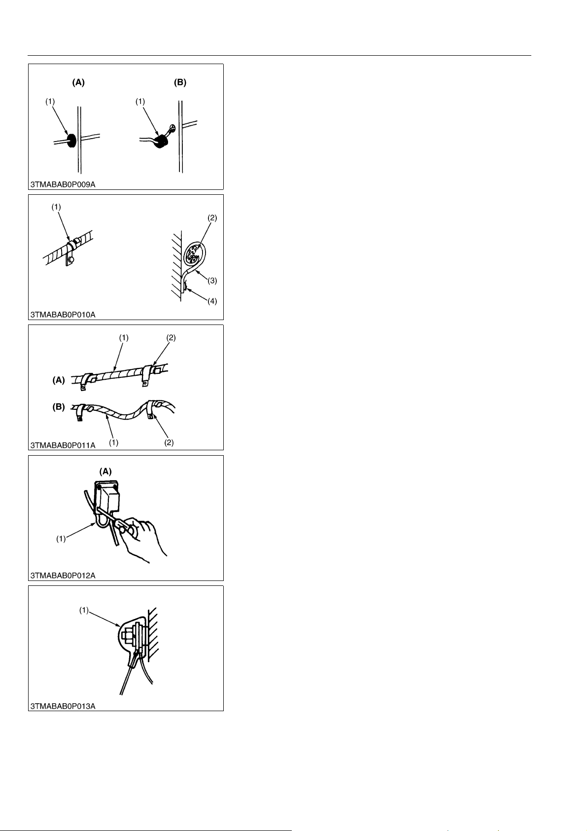
• Securely tighten wiring terminals.
(1) Correct
(Securely Tighten)
(2) Incorrect
(Loosening Leads to Faulty Contact)
WSM000001GEG0063US1
• Do not let wiring contact dangerous part.
(1) Dangerous Part (Sharp Edge)
(2) Wiring (Incorrect)
(3) Wiring (Correct)
(4) Dangerous Part
WSM000001GEG0064US1
• Repair or change torn or aged wiring immediately.
(1) Aged
(2) Torn
(3) Insulating Vinyl Tape
WSM000001GEG0065US1
G-3
B1830,B2230,B2530,B3030, WSM
KiSC issued 05, 2012 A
GENERAL
• Securely insert grommet.
(1) Grommet (A) Correct
(B) Incorrect
WSM000001GEG0066US1
• Securely clamp, being careful not to damage wiring.
(1) Clamp
(Wind Clamp Spirally)
(2) Wire Harness
(3) Clamp
(4) Welding Dent
WSM000001GEG0067US1
• Clamp wiring so that there is no twist, unnecessary sag, or
excessive tension, except for movable part, where sag be
required.
(1) Wiring
(2) Clamp
(A) Correct
(B) Incorrect
WSM000001GEG0068US1
• In installing a part, take care not to get wiring caught by it.
(1) Wiring (A) Incorrect
WSM000001GEG0069US1
• After installing wiring, check protection of terminals and
clamped condition of wiring, only connect battery.
(1) Cover
(Securely Install Cover)
WSM000001GEG0070US1
G-4
B1830,B2230,B2530,B3030, WSM
CAUTION
KiSC issued 05, 2012 A
[2] BATTERY
GENERAL
• Take care not to confuse positive and negative terminal posts.
• When removing battery cables, disconnect negative cable first.
When installing battery cables, check for polarity and connect
positive cable first.
• Do not install any battery with capacity other than is specified
(Ah).
• After connecting cables to battery terminal posts, apply high
temperature grease to them and securely install terminal covers
on them.
• Do not allow dirt and dust to collect on battery.
• Take care not to let battery liquid spill on your skin and
clothes. If contaminated, wash it off with water
immediately.
• Before recharging the battery, remove it from the machine.
• Before recharging, remove cell caps.
• Do recharging in a well-ventilated place where there is no
open flame nearby, as hydrogen gas and oxygen are
formed.
WSM000001GEG0071US1
[3] FUSE
[4] CONNECTOR
• Use fuses with specified capacity.
Neither too large or small capacity fuse is acceptable.
• Never use steel or copper wire in place of fuse.
• Do not install working light, radio set, etc. on machine which is
not provided with reserve power supply.
• Do not install accessories if fuse capacity of reserve power
supply is exceeded.
(1) Fuse
(2) Fusible Link
(3) Slow Blow Fuse
WSM000001GEG0072US1
• For connector with lock, push lock to separate.
(A) Push
WSM000001GEG0073US1
• In separating connectors, do not pull wire harnesses.
• Hold connector bodies to separate.
(A) Correct (B) Incorrect
WSM000001GEG0074US1
G-5
 Loading...