

Page 1

SPECIFICATIONS----------1
DIMENSIONS
CONTENTS
13
M.
MECHANISM
1.ENGINE------------
[1] AUTOMATIC
RELIEVING
[2]
CARBURETOR
[3]
SUB
PTO
(Except
G.
GENERAL
[1] IDENTIFICATION ······································5-1
GENERAL
,[2]
[3]
GENERAL
[4]
LUBRICANTS
[5]
TROUBLESHOOTING
SERVICING
[6]
[7] TIGHTENING
(1)
Tightening
Screws, Bolts and Nuts ......................
Tightening
(2)
Use
Screws, Bolts and Nuts ................
[8] MAINTENANCE
[9]
CHECK
(1) Check Points
or
Daily··
(2) Check Points
or
Initial 20 Hours .............................
(3) Check Points
or
50
(4) Check Points
or
100 Hours ......................................
(5) Check Points
or
300 Hours ......................................
SPECIAL
[10]
1.
ENGINE
[1]
SEPARATING
DISASSEMBLING
[2]
ENGINE
CHECKING
DISASSEMBLING
(1) External Components .......................
(2) Cylinder Head and Valves .................
(3) Camshaft, Piston and Crankshaft ......
SERVICING
(1) Valves··· .... · .... ···........··.......... · .... ·..· ....
(2) Cylinder
PRESSURE
MECHANISM .......................
........................................ M-3
SHAFT
-P,
-PC,
-PCC) ··..........······ .. ···· .... ·M-3
DISASSEMB~:
S.
SAFETy···································
PRECAUTION
AND FUEL.······ ...... ·············S-3
SPECIFICATIONS··················S-ll
TORQUES
Torques
Torques
CHECK
AND MAINTENANCE ................
of
..
·.····..······............................
of
of
Hours ........................................
of
of
TOOLS ··...... ···· ......
ENGINE
AND
BODY
·.·· ...... ··· ....
AND
ADJUSTING
AND
...............................................
liner
..........................
································S-5
.........................
for
Important
for
General
LIST
.................
Each
Use
First
Month
Every 3
Every 6
Every Year
....................................
Months
Months
·· ..
·········· .... ·5-43
·······........ · .... · ..·· ..
ASSEMBLING
··
.. ······· ....···....
····..........
ASSEMBLING
.... ···S-47 [2]
....·
M-1
M-l
S-24
S-24
S-24
S-27
S-29
S-29
S-33
S-35
S-35
S-41
S-47
·5-47
·S-51
·· ..
·S-51
..
S-51
S-51
S-59
S-61
S-71
S-71
S-77
5-1
5-3
2. TRANSMISSION
(EXCEPT
[1]
3. MOWER
(EXCEPT
NG
::~~~:~::~::::::i::CE)um.muu.u.~·:!
[3] FUEl
[4] IGNITION
[5]
[6]
2.
MOWER
3.
TRANSMISSION
(EXCEPT
[1]
4.
FRONT
5.
HANDLE AND
-P,
-PC,
-PCC)
POWER
(4) Connecting Rod, Crankshaft and
CHECKING
(1) Governor ...........................................
(2)
DISASSEMBLING
(1) Carburetor ........................................
CHECKING
(1) Spark
(2)
(3) Stop Switch .......................................
STARTING
CHECKING
DISASSEMBLING
SERVICING
CHARGING
CHECKING
DISASSEMBLING
SERVICING
SEPARATING
DISASSEMBLING
TRANSMISSION
DISASSEMBLING
SERVICING
DISASSEMBLING
SERVICING
CHECKING
DISASSEMBLING
TRAIN
BLADE
.p, .T)
Camshaft···········································5-83
SYSTEM
ChokeRod·
Ignition
BLADE
-P,
-PC,
WHEEL
...................................... M·5
CLUTCH
---------
........................................
AND
ADJUSTING
............ ··········· ... ···· ...... ··.·S·91
AND
SYSTEM
AND
PI
ug ......................................... 5-95
Unit
SYSTEM
..
···........ · ...... · ..···....· .... ···..· .. · ....
............................................. S-l
SYSTEM
...... · .................. · ..·
... ············ ...... ··· .... ············ ......
-PCC)
.............................................
AND
.............................................
DISCHARGE
AND
................................
ADJUSTING
.....................................
········..······················S-99
AND
·····..· ...... ··· ..···..· ....
CLUTCH
AND
TRANSMISSION
AND
...................................
AND
REAR
AND
ADJUSTING
AND
···················S-91
ASSEMBLING
···················5-95
ASSEMBLING ··..
.. ·· ..
AND
BLADE
ASSEMBLING ..·..S-105
ASSEMBLING
ASSEMBLING
WHEEL--S-121
ASSEIVIBLING ··..
GUARD
..........
ASSEMBLING
·······S-93
· .......... S-l
- S-105
....····......
·....
.... ·S-l13
--S-129
·· ..
.... ·S-129
·S-101
···S-129
M-5
M-9
5-91
S-91
S-93
S-95
S-95
S-97
S-99
01
S-103
03
S-105
S-111
S-lll
S-111
S-113
S-115
·S-121
S-125
'=
.:.
~
.:.
~
Page 2

TABLE
DE
MATIERES
CARACTERISTIQUES
DIMENSIONS 13
1.
MOTEUR
[1] MECANISME
AUTOMATIQUE ..................................... M-2
[2]
CARBURATEUR
[3]
ARBRE
DE
FORCE
G.
GENERALITES
[1] IDENTIFICATION ......................................
(2]
SECURITE
[3]
PRECAUTION
[4) LUBRIFIANT5
(5) INCIDENT5
[6]
CARACTERI5T1QUE5
ET
REGLAGE5
[7]
COUPLE5
(1) Couples
boulons
utilisation
(2) Couples
boulons
generale ........................................... 5-25 (1) Bougie d'all
[8] TABLEAU
D'ENTRETIEN
(9] VERIFICATION
(1) Points
utilisation
(2) Points a
premieres 20 heures ·························5-34
(3) Points
ou
toutes
(4) Points
ou
toutes
(5) Points a
ou
toutes
[10)
OUTILS
1. MOTEUR 5-48
[1) 5EPARATION
DEMONTAGE
[2)
CORP5
VERIFICATION
DEMONTAGE
(1) Composantes externes ......................
(2) Culasse
(3)
Arbre
et
vilebrequin
---------5
DE
DECOMPRESSION
......................................
AUXILIAIRE
(SAUF
GENERALE
DE
DE
de
et
particuliere
de
et
DE5
a
verifier
ou
verifier
a
verifier
les
a
verifier
les 100 heures ....................
verifier
les 300 heures ....................
SPECIAUX
DU
MOTEUR .............................
et
DE
PRISE
-P,
-PC,
-PCC)
S.
DEMONTAGE
·······························5-2
GENERAlE5 .......................
ET
CARBURANT ················5-4
CONCTIONNEMENT ·········5-7
DETAILLEES
········································5-16
5ERRAGE
serrage
ecrous
serrage
ecrous
PERIODICITES
.........................................
ET
journellement
50
DU
ET
ET
ET
sou pa
·························5-25
pour
vis,
d'une
......................
pour
vis,
d'utilisation
ENTRETIEN
toutes
premier
toutes
heures ······················5-36
toutes
MOTEUR·
REMONTAGE ....· .... · .... ·S-48
REGLAGE
REMONTAGE ........ · ......
chaque
mois
les 3 mois
les 6 mois
tous les ans
.................................
..··
................... 5-52
pes
.......................... 5-60
acames, piston
...................................
M.
MECANISME
M·2
M-4
............. M-4
S-2
S-2
S-4
S-25
S-27
···············S-30
............. 5-30
ou
S-36
S-42
S-44
........ · ..·
..
S-48
S-52
S-52
S-52
S-62
2. TRANSMISSION (SAUF
[1] CIRCULATION
3.
EMBRA Y
(SAUF
4. DEMARRAGE
(-SCE.
ET
ENTRETIEN
(3] 5Y5TEME D'ALIMENTATION ······· ..· .. · .... 5-92
(4]
[5]
(6]
2.EMBRAYAGE
3. TRANSMISSION (SAUF-P.
[1] SEPARATION
(2] TRANSMISSION
4.
ROUE
5.
POIGNEE
AGE
DE
-P,
-T) M-10
DES
-TCE)
ENTRETIEN
(1) 50upapes .......................................... 5-72
(2) Chemise
(3) Piston
(4) Bielle,
arbre acames .................................... 5-84
VERIFICATION
(1) Regulateur··· ..................................... 5-92
(2) Tige de starter .................................. 5-92
DEMONTAGE
(1) Carburateur ......................................
SYSTEME
VERIFICATION
(2) Bloc
(3)
Interrupteur
SYSTEME
VERIFICATION ·· .... · ............ ····· ................ S-100
DEMONTAGE
SYSTEME
VERIFICATION ········ ................ ····· ........ · .. S-104
DEMONTAGE
ENTRETIEN
TRANSMISSION ................................... S-112
DEMONTAGE
DEMONTAGE
ENTRETIEN
AVANT
DEIVIONTAGE
ENTRETIEN
VERIFICATION
DEMONTAGE
..............................................
de
et
segment .............................
vilebrequin
D'ALLUMAGE
de
commande
DE
DE
DE
··········....·..······· ............ ··· ...... S-106
............................................ S-116
ET
......··............ · .... ·..······..·..· .... ·S-126
ET
GARDE
.p.
-PC.-PCC)--M-6
DE
PUISSANCE
LA LAME
CABLAGES
cylindre
ET
ET
ET
umage
d'arret
DEMARRAGE .... ··· .... · .. ···S-100
ET
CHARGE
LA LAME
ET
DE
ET
ET
ROUE
ET
ET
ET
.........................
et
REGLAGE
REMONTAGE
REGLAGE
............................
d'allumage
..........................
REMONTAGE ............
....·· .................. ·S-l 04
REMONTAGE ··· ..·· .. ····S-106
-PC.-PCC)--S-112
LA
REMONTAGE ............
..··..
· .. ······......· .... ·······..·S-114
REMONTAGE ............ S-114
ARRIERE
REMONTAGE ............
D'EJECTION S-130
REGLAGE
REMONTAGE ............ S-130
.......•.......
··················
.............. 5-94
..··..
· ................ ·5-96
....
·· .. ·..
·········5-96
......... 5-96
ET
LAME-S-106
................. S-130
M-6
M-13
S-72
S-78
S-80
..5-92
5-94
S-96
S-98
S-102
S-112
S-122
S-122
Page 3

VERZEICHNIS
TECHNISCHE
ABMESSUNGEN 13
1. MOTOR
[1]
AUTOMATISCHER DRUCKENT-
LASTUNGSMECHANISMUS .................... M-2
[2]
VERGASER
[3]
HILFSZAPFWELLE
(AUBER
G.
AllGEMEINES
[1} KENNZEICHNUNG ...................................
[2] ALLGEMEINE
SICHERHEITSVORSCHRIFTEN
[3} ALLGEMEINE VORKEHRUNGEN ..............
[4] 5CHMIERMITTEL UNO
[5]
FEHLERSUCHT
[6} WARTUNGSDATEN ............................... S-20
[7] ANZUG5DREHMOMENTE ......................
(1)
(2)
[8] WARTUNGS-CHECKLl5TE ......................
[9]
OBERPROFUNG
(1) Nach
(2) Nach 1
(3)
(4)
(5) Jtihrlich
[10]
1.
MOTOR S-48
[1]
AUSBAU UNO EINBAU ....·
[2} MOTORKORPER ....................................
OBERPROFUNG
AUSBAU UNO EINBAU · .... ···
(1) AuBere Bauteile ................................
(2)
(3) Nockenwelle, Kolben
DATEN
Anzugsdrehmomente
Schrauben, Bolzen
Anzugsdrehmomente
allgemeine
Bolzen
taglich
ersten
OberprOfende Punkte ....... · ....
Aile 3 Monate
Stunden zu OberprOfende
Punkte ..............................................
Aile 6 Monate
5tunden
Punkte .............................................. 5-36
uberprOfende Punkte ...................
zu
SPEZIALWERKZEUGE
TRENNEN
Zylinderkopf
und
Kurbelwelle
---------
M.
.............................................
-P,
-PC,
-PCC)
····························M-4
S.
AUSBAU
...................
KRAFTSTOFF
ABELLE
5chrauben,
und
Muttern
jeder
Verwendung
zu OberprOfende Punkte .......
Monat
20
Stunden zu
zu OberprOfende
oder
DES
UNO
.............................
fUr
wichtige
und
Muttern
fur
..........................
UNO WARTUNG ..........
oder
oder
nach
den
··..···.... ·5-34
oder
aile
50
oder
aile 100
aile
300 Stunden
............................
MOTOR5 .......................
..
· .............. · .. · ..5-48
EINSTELLUNG
..
· ................
und
Ventile
...............................
.................. 5-60
MECHANISMUS
.......
........
........
9
M-2
M-4
S-2
S-2
S-2
S-4
S-4
S-9
S-26
S-26
S-26
S-28
S-30
S-30
S-36
S-42
S-44
S-48
S-52
S-52
·S-52
S-52
S-62
2.
GETRIEBE
[1]
3.
MESSERKUPPlUNG (AUBER -p. -T)
4. seHAlTPLAN (-SeE. -TeE) M-13
UNO
WARTUNG
WARTUNG ..............................................
(1)
(2) LaufbOchse ....................................... 5-78
(3) Kolben
(4) Pleuelstange,
[3}
OBERPROFUNG
(1) Drehzahlregler ..................................
(2) Chokestab .........................................
AU5BAU UNO EINBAU ··· ..··· ........ · .... · ......
(1) Vergaser ........................................... S-94
[4}
OBERPROFUNG
(1) Zundkerze ........................................ S-96
(2)
(3) Abstellschalter ..................................
[5}
OBERPROFUNG ..··
AUSBAU UNO ZU5AMMENBAU
WARTUNG
[6} LADESY5TEM ...................................... S-104
OBERPROFUNG
2.
MESSERKUPPLUNG
AUSBAU UNO EINBAU ········
WARTUNG ..· ................ ···
GETRIEBE
3.
[1]
AUSBAU UNO EINBAU ·· ........ · ..· ...... · .. ·
[2]
AUSBAU UNO EINBAU .............. ··· ..·..· .. ·S-114
WARTUNG ............................................ S-116
4. VORDERRAD UNO HINTERRAD S-122
AU5BAU UNO EINBAU
WARTUNG ............................................
5.
HANDGRIFF UNO AUSWURFSeHUTZ - S-130
OBERPROFUNG
AU5BAU UNO EINBAU ...... · .......... · ........ S-130
(AUBER
KRAFTOBERTRAGUNG
Ventile
und
Nockenwelle ..............................
KRAFTSTOFFSYSTEM
ZONDANLAGE
Zundeinheit
ANLASSERSY5TEM
(AUBER
TRENNEN
GETRIEBE
-Po
·PC.
..............................................
und Kolbenring
Kurbelwelle
UNO
EINSTELLUNG
.......................................
UNO
EINSTELLUNG
......................................
.......... · ..· ................ ·S-100
...... · .. · ..·..··..· .... ·· ..· ...... 5-100
··
.. ·..··..
· .... ···· .. · ..···· .... ····· .... ·
....· ............
UNO
-P.
-pe.-peC)
DES
GETRIEBE5
....· ........ · ..· .... · .... ···....· .... · ..·
UNO
-PCC)
..........................
--
....................
............................
....
··
......··..·..
MESSER
..
· .... ··....· .... 5-106
.. ··..···
.. ·..
..................
.... ·····................ ·S-122
EINSTELLUNG
M-6
M-6
M-10
S-72
S-72
S-80
S-84
S-92
S-92
······
..
S-92
S-92
S-94
S-96
........
S-96
S-96
S-98
··
......S-102
..
S-102
·· ..· .. 5-104
S-106
· ...... ··S-106
S-112
S-112
S-112
..
..
5-114
S-126
...... S-130
Page 4

SPECIFICATIONS
SPECIFICATIONS
[Engine]
WS019WS021 WSM,10482
Machine
Engine
Type
Number
Bore x Stroke
Maximum
Maximum
Compression Ratio
Cooling System
Lubricating System
Starting System
Ignition
Model
Model
of
Cylinders
Displacement
mum
Horsepower
Torque
No-load Speed
System
W5019-P
GH
Recoil starter
W5019-PC
I
150V-L-P2
(With
Non-contact
W5019-T
GH
Air-cooled, 4-cycle, OHV gasoline engine
1
q,
61 x 50
mm
(q,
2.4 x 2.0 in.)
cm3 (8.9 co.in.)
146
3.73
kW
13600
rpm
5.0
HP
13600
rpm
9.8 N'm
12800
rpm
12800
12800
rpm
8.3
air
cooling
type
(Transistor controlled)
automatic
magneto
kgf·m
1.0
7.2 ft-Ibs
3050 rpm
Forced
Splash
pressure relieving mechanism)
ignition
I
150V-L-
rpm
WS019-TC
T2
W5019-TCE
GH1S0V-L-TE2
Electric Starter
(12V,0.12kw)
Ignition
Spark Plug
Carburetor Type
Governor Type
Air
Battery
Engine Oil
Fuel
Dry
Timing
Cleaner
Weight
Type
r.
Capacity
type,
B.T.D.C.
(NGK)
butterfly
flywheel
element
type
0.40 rad. (23°)
BPR2ES
Horizontal
Centrifugal
Dry-type paper
-
A.P.L type,
(0.6 U.s.qts. 0.53Imp.qts.)
Unleaded gasoline, 87 OCTANE
(1.6 U.Sqts. 1.32Imp.qts.)
14.3I<g
(31.5lbs)
SE
0.61
1.51
ISF
class
valves
12V,2.9Ah
minimum
IJillL
Page 5

WS019W5021 WSM,10482
SPECIFICATIONS
W5021-PC
GH
150V-L-P
Recoil
W5021-PCC W5021-T
Air-cooled, 4-cycle, OHV gasoline
.p
61)(
146
3.73
5.0
9.8 N·m
1.0
7.2
Forced
starter
(With
automatic
Non-contact
pressure relieving mechanism)
magneto
W5021-TC.
I
GH150V-L-T
1
50
mm
(.p
2.4)( 2.0 in.)
cm 3 (8.9 cu.in.)
kW
13600 rpm
HP/3600
kgf·m
ft-Ibs 12800 rpm
3050 rpm
Splash
ignition
rpm
12800 rpm
12800
8.3
air
cooling
type
(Transistor controlled)
rpm
SC
engine
W5021-SCC,
GH150V-L-TC
HTC
W5021-SCE,
GH150V-L-TE
Electric sta
(12V,O.12kW)
TCE
rter
I
I
I
I
1.51
(1.6 U.Sqts.
1.32Imp.ats.)
3.51
0.7
U.S.qts.
3.08Imp.qts.)
Horizontal
Unleaded gasoline, 87
14.3 kg
(315Ibs)
type,
B.T.D.C.
(NGK)
butterfly
flywheel
element
valves
type
0.40 rad. (23")
BPR2ES
Centrifugal
Dry-type paper
-
A.P.1.
type.
SE
ISF
class
(0.6 U.5.qts. 0.53 Imp.qts.)
(1.6 U.S.qts. 1.32 Imp.qts.)
0.61
OCTANE
LSI
minimum
3.5 I
(3.7 U.S.qts
3.08Imp.qts.)
14.5I<g
(32.0Ibs)
12V.2.9Ah
1.51
0.6
U.S.qts
1.32Imp.qts.)
kg
15.5
(34.2 Ibs)
I
2
Page 6

SPECIFICATIONS
W5019W5021 WSM. W482
[Walk Behind
Machin
..
Model
Cutting
I
Push
81ade
Overall Length
Overall
Overall
Handle
Tread
Wheel8ase
Tire Size (Diameter x
Cutting
Blade Speed
Blade Thickness
Width
Type I Self Propelled
Clutch System
Width
Height
Width
Height
(at
engine
Mower]
Front
Rear
Width)
3050 rpm)
W::;019-P
(with
None
mechanism)
I
Push
type
slip I
W5019-PC
81ade
brake
clutch
W5019-T
470
mm
None
(with
mechanism)
1705 mm (67.1 in.)
510
mm
(20.0 in.)
1030
mm
460 mm (18.1 in.)
mm
mm
mm
51
mm
76 mm (5/8
m/s
(252.7 ftls)
3.2
mm
(0.13 in.)
(16.1
(17.8 in.)
(23.5 in.)
(8.0 x 2.0 in.)
203 x
16
to
75.0
408
452
596
(19 in.)
slip I
(40.6 in.)
in.)
to
3 in.)
W5019-TC
I
Self propelled
Blade
I
brake
W5019-TCE
clutch
Grass Catcher
Travelling Speed
Speed Range
Drive Clutch System Ball
Transmission
weight
Dry
Bag
Capacity
Type
Oil
Capacity -
681
-
-
- Hypoid
39 kg (85.8Ibs) I40 kg (88.2 Ibs)
(18.0 U.S.gal.. 14.9Imp.gal.)
2.8km/h,
(1.7 mph, 2.5 mph)
2 speeds
gear
0.11
(0.1
U.S.qts.,O.09Imp.qts.)
41kg
(90.2Ibs) I 44 kg (96.8Ibs) I
oil, HD80W-HD90W
4.0 km/h
forward
type
47.5I<g
(104.7Ibs)
3
Page 7
WS019WS021 WSM,10482
SPECIFICATIONS
W5019-PC W5021-PCC
Push
type
Blade brake clutch
472
mm
(18.6 in.)
499
mm
(19.7 in.) 504
203x51
(8.0 x 2.0 in.) (8.9 x
16to
(S/8
to
76
3 in.)
mm
mm
481
mm(18.9in.)
mm
225 x
25
to
(1
to
(19.8 in.)
59
mm
2.3
in.)
88 mm
3.5 in.)
WS021-T
(with
None
mechanism)
203xSl
16
W5021-TC,
I
530
mm
(21
in.)
slip
I
(697
1770 mm
566 mm (22.3 in.)
mm
1040
460 mm (18.1 in.)
472
mm
mm
499
633
mm
mm(8.0x2.0in.)
to
76
mm
84.6 m/s (279.3 ftls)
mm
4.0
in.)
(40.9 in.)
(18.6 in.)
(197
in.)
(24.9 in.)
(5/8
to
(0.16 in.)
3 in.)
SC
Self propelled
W5021-SCC,
Blade brake clutch
481
504 mm (19.8 in.) 499
HTC
mm
(18.9 in.) 472 mm (18.6 in.)
22SxS9mm
2.3
(8.9 x
25t088mm
(1
in.) (8.0 x 2.0 in.)
to
3.5 in.)
WS021-SCE,
203xSl
16to
(518
mm
(197
76 mm
to
3 in.)
TCE
in.)
mm
42.5 kg (94Ibs)
-
-
-
-
48.5 kg (107Ibs)
7S1 (19.8 U.S.gal., 16.Slmp.gal.)
2.8 km/h, 4.0 km/h (2.5 mph,
43
kg (94.6
(1.7 mph,
(0.1
U.S.qts.,0.09Imp.qts.)
Ibs)
2.S
mph)
0.11
46 kg (101.Slbs)
I
Hypoid gear oil, HD80W-HD90W
2 speeds
Ball type
-SCC
4.1
km/h, 5.6 km/h
3.S
-HTC
3.4 km/h,
(2.1
forward
0.171(0.18
50.5 kg (111.5Ibs)
4.1
mph,
2.S
US.qts.,
0.15Imp.qts.)
mph)
km/h
mph)
kmlh,
2.8
(1.7 mph,
0.11
4.0 km/h
(0.1
0.09Imp.qts.)
49 kg (108Ibs)
2.5
mph)
U.S.qts.,
4
Page 8

SPECIFICA
nONS
CARACTERISTIQUES
[Moteur]
W5019W5021 WSM,10482
Modele
Modele du
Type
Nombre de cylindres
AI~sage
Cylindree
Puissance maximum
Couple
Regime maximum ~ vide
Rapport
Systeme de refroidissement
Systeme de lubrification
Systeme de
Systeme d'allumage
Temps d'allumage
moteur
x Course
totale
maximum
volumetrique
d~marrage
W5019-P
I
GH150V-L-P2
Refroidissement par air
Systeme d'allumage
W5019-PC
forc~,
4 temps, soupape en UHe,
61 x 50mm
3,73
kW
5,0
CV
9,8 N'm
1,0 kgf·m 12800
Refroidissement par
Lubrification par
Lanceur de d'emarrage
sans
contact par
0,40 rad. (23°) avant P.M.H.
W5019-T
GH150V-L-T2
1
3
146
cm
{3600
13600
{2800
3050tr/mn
8,3
barbotage
magneto
I
tr/mn
tr/mn
tr/mn
tr/mn
air
force
(Control~
W5019-TC
moteur ~ essence
par transistor)
W5019-TCE
GH150V-L-TE2
Demarreur
electrique
Bougie d'allumage
Carburateur
Filtre
~
air
R~gulateur
Batterie
Huile
moteur
Carburant Type
Poids ~ sec
Type
Capacit~
Capacit~
BPR2ES
(NGK)
Vanne-papillon, type
Type
seches,
element
Systeme ~ masselottes centrifuge
en papier
-
Classe
SE
{SF,
type
0,61
Essence
sans
plomb, 87
14,3 kg
OCT
1,51
horizontal
rempla~able
A.P.1.
ANES
minimum
12V,2.9 Ah
I
15,5 kg
5
Page 9

WS019-WS021
WSM,10482
SPECIFICATIONS
W5021-PC
I
GH150V-l-P
W5021-PCC
Refroidissement par
Syst~me
d'allumage
lanceur
W5021-T
GH150V-l-T
air
force, 4 temps, soupape en tOte,
61
146cm
3.73
kW
5.0
CV
9,8 N'm 12800
1,0 kgf·m 12800
3050
Refroidissement par
lanceur
de
d'emarrage
sans
contact par
OAO
rad. (23°) avant P.M.H.
W5021-TC,
J
1
x50mm
3
13600
tr/mn
13600
tr/mn
tr/mn
tr/mn
tr/mn
8,3
air
force
de d'emarrage
magneto
SC
(Controle par transistor)
moteur
W5021-SCC,
GH150V-l-TC
1\
essence
HTC
W5021-SCE.
GH
150V-l-TE
D~marreur
electrique
TCE
1,51
I
3.51
Type
Essence
I
14.3kg
BPR2ES
Vanne-papitlon.
s~ches,
element
Syst~me
1\
masselottes centrifuge
Classe
SE I SF.
sans
plomb, 87
(NGK)
type
en papier
type
0,61
OCTANES
1,51
horizontal
rempla~able
A.P.1.
minimum
12V,2.9Ah
3.51
14,5 kg 15.5
1,51
kg
6
Page 10

CARACTERISTIQUES
[Tondeuse]
W5019W5022 WSM,10482
Modele
Largeur de coupe
Modele apousser I Autotractee
la
Systeme d'embrayage de
longueur
largeur
Hauteur hors-tout
Largeur de poignee
Voies
Empattement
Pneus
Hauteur de coupe
Vitesse de la lame (Moteur: 3050
Epaisseur de
(apacite
hors-tout
hors-tout
(Diametre
la
du
sac
)(
Largeur)
lame
aherbe
lame
Avant
Arriere
tr/mn)
W5019-P
Modele a pousser
Autun
~gede
I
W5019-PC
lame
W5019-T
470mm
1705mm
510mm
1030 mm
460mm
408mm
452mm
596mm
203)(51 mm
16
a76 mm, 6
75,0 m/s
Autun
3,2mm
681
W5019-TC
I I
Autotractee
Embrayage de frein de lame
I
eta
pes
W5019-TCE
Vitesses d'avancement
Gamme de vitesse
Systeme d'embrayage
Huile de
transmission
Poidsa
sec
d'entrainement
Type
(apacite
39
kg
2,S
km/h, 4,0 km/h
-
-
-
I
40kg
41kg
2 vitesses en marche avant
Type
abilles
Huile pour engrenages
hypoldes, HDSOW-HD90W
0,11
44kg
I I
47.5 kg
7
Page 11

W5019·W5021
WSM,10482
CARACTERISTIQU
ES
W5019-PC W5021·PCC
Modele 8 pousser
Embrayage
472mm
499mm
203x51mm
16876mm
6
eta
pes
de
frein de lame
225x59mm
25888
481
mm
504mm
mm
6 etapes
W5021-T
530mm
Aucun Embrayage de frein de lame
1770mtn
566mm
1040 mm
460mm
472mm
499mm
633mm
203 x51 mm
166
76mm.
84.6
4.0mm
W5021-TC.
6 eta
m/s
pes
SC
Autotractee
W5021-SCC.
481
mm
504mm
225 x 59 mm
25888
6 eta
pes
HTC
mm
751
W5021-SCE.
472mm
499mm
203x
51
16876mm
6etapes
TCE
mm
I
I
I
42.5 kg
-SCC:
-
-
-
-
-
48.5 kg
2.8 km/h. 4.0 km/h
43kg
-HTC:
2 vitesses en marche avant
Type 6 billes
Huile pour engrenages hYPoides. HD80W-HD90W
0.11
46 kg 50.5 kg
4.1
5.6 km/h
3,4kmlh
4,1
0.171
kmlh
2.8 km/h. 4,0 km/h
km/h
0.11
49 kg
8
Page 12

TECHNISCHE
DATEN
TECHNISCHE DATEN
[Motor]
~
Modell
Motormodell
Typ
Zylinderzahl
WS019-P
I
GH
150V-l-P2
luftgekOhlter,
WS019-PC
4-Takt-Benzinmotor
WS019-T
mit
1
WS019WS021 WSM,10482
W5019-TC
I
GH
150V-l-T2
oben gesteuerten Ventilen
WSOI9-TCE
GH
lS0V-l-TE2
Bohrung
i
Cylindree
MaximalePS
Maximale Drehmoment
Maximale
VerdichtungsverhAltnis
KOhlungssystem
Schm
Anlal3system
ZOndanlage
ZOndversteliung
ZOndkerze
Vergaser
luftfilter
Regier
Batterie
)(
Hub
totale
leerlaufdrehzahl
ieranlage
61)(SOmm
3
146cm
3.73
kW
(5,0
PS)
13600 U/min
9,8 N'm (1,0 kp·m)
3050 U/mn
GeblasekOhlung
Spritzschmierung
ROckstol3anlasser
Kontaktl05e MagnetzOndung (Transistorgesteuert)
OAO
rad. (23°)
BPR2ES
Horizontal-Drosselklappenvergaser
Auswechselbarer Papiereinsatz in trockener AusfOhrung
Fliehkraftregler
12800 U/min
8,3
'lor
(NGK)
OT
-
Elektrisch
Zellenanlasser
12V,2,9Ah
mit
MotorOI
Kraftstoff
leergewicht
Sorte
FassungsvermOgen
Sorte
FassungsvermOgen
A.P.L
Typ der
Unverbleites Benzin
14,3 kg
Klasse
SE
ISF
0,61
mit
mindestens 87 OKTAN
1.51
I
15,5 kg
9
Page 13

WS019·WS021
WSM.10482
TECHNISCHE
DATEN
WS019-PC
I
GH150V-L-P
WS021-PCC W5021-T
LuftgekOhlter,
4-Takt-Benzinmotor
3,73
9,8 N·m (1,0 kp·m)
ROckstoBanlasser
Kontaktlose
kW
Spritzschmierung
Magnetzundung
0.40 rad. (23°) vor OT
W5021-TC.
I
GH150V-L-T
mit
oben gesteuerten Ventilen
1
61x50mm
3
146cm
(5,0
PS)
13600 U/min
12800
3050 U/min
8,3
GebUlsekOhlung
(Transistorgesteuert)
BPR2ES
(NGK)
Ulmin
SC
W5021-SCC,
GH150V-l-TC
HTC
W5021-SCE,
GH150V-l-TE
Elektrisch
Zellenanlasser
TCE
mit
1,51
I
Horizontal-Drosselklappenvergaser
Auswechselbarer Papiereinsatz in
-
A.P.1.
Unverbleites Benzin
3,51
I
14,3 kg
trockener
Fliehkraftregler
Typ
der
Klasse
0,61
mit
mindestens 87 OKTAN
1,51
SE 1SF
AusfOhrung
3,51
14,5 kg
12V,2,9Ah
1,51
15,5 kg
10
Page 14

TECHNISCHE
DATEN
[Rasenmaher]
WS019·WS021 WSM,10482
Modell
Schnittbreite
SchiebeausfOhrungl Radantrieb
Messerkupplungssystem
Gesamtlange
Gesamtbreite
GesamthOhe
G riffsta ngen breite
Spurweite
Radstand
ReifengrOBe (Durchmesser x Breite)
SchnitthOhe
Messergeschwi ndig k
(Motordrehzahl: 3050 U/min)
Messerdicke
Vorn
Hinten
eit
W5019-P
SChiebeausfOhrung
J
-
W5019-PC
Messerbrems-
kupplung
I
16
bis
WS019-T
470mm
-
170S
510mm
1030mm
460mm
408mm
452mm
596mm
203xS1
76 mm.
75.0
3.2mm
mm
mm
In
6 Schritten
m/s
1
W5019-TC
Radantrieb
Messerbrems-kupplung
J
W5019-TCE
I
I
FassungsvermOgen
Fahrgeschwindigkeit
Anzahl der Gange
Antrie
bsk
u pplu ngssystem
Sorte
GetriebeOI
Fassungsvermogen
leergewicht
des
Grasfangsack
39
kg
681
-
-
-
-
-
I
40kg
4lkg
2.8 km/h, 4,0 km/h
2 VorwArtsgAnge
KugelausfOhrung
HypoidgetriebeOI.
HD80W-HD90W
0,11
1
44kg
I
47.S
kg
11
Page 15

WS019WS021
WSM,10482
TECHNISCHE
DATEN
W5019-PC
SchiebeausfOhrung
Messerbrems-k upplung
472mm
499mm
203 x
51
mm
16
bis
76
mm
In 6 Schritten
W5021-PCC
481
mm
504mm
225x59
25
In
mm
bis88mm
6 Schritten
W5021-T
-
16
bis
W5021-TC,
530mm
1770mm
566mm
1040 mm
460mm
472mm
499mm
633mm
203 x51 mm 225
76
mm,ln
6 Schritten
84.6
m/s
4.0mm
SC
Radantrieb
W5021-SCC,
Messerbrems-kupplung
HTC
481
mm
504mm
x59mm
25
bis88 mm
In 6 Schritten
W5021-SCE,
472mm
499mm
203 x
51
16
bis
76 mm
In 6 Schritten
TCE
[
I
I
I
[
mm
42,S
kg
751
4,1
-SCC:
-
-
-
-
-
48,S
I
kg
2,8 km/h, 4,0 km/h
0,11
431<:g
-HTC:
2 VorwArtsgAnge
Kugelausfuhrung
HypoidgetriebeOl, HD80W-HD90W
I
46kg
5.6 kmth
3,4 km/h
4.1
0,171
50,S
kmth
km/h
kg
2.8 km/h, 4,0 km/h
0,11
49
kg
12
Page 16

DIMENSIONSI
DIMENSIONS
DIMENSIONS
I
ABMESSUNGEN
W5019W5021
WSM.l0482
DIMENSIONS
ABMESSUNGEN
~w
(ON
(7\N
~N
~-
.:1''''
0'"
",In
W5019 :
W5021
W5021
464
(PCC,
(PC,
T,
WS019:
W5021
W5021
(18.27)
SCC,
HTC)
TC,
se. seE,
408 (16.06)
(PCC,
(PC,
T,
: 540 (21.26)
SCC,
HTC):
TC,
sc.
reEl:
SCE.
528
481
TCE):
(2079)
(18.94)
472
(1858)
W5019:
W5021
(PCC,
W5021 (Pc'
W5019:
W5021 (PCe.
W5021
452 (17.80)
(PC.
510 (20.08)
scc,
HTC)
T,
TC,
sc. seE.
SCC,
HTC)
T.
re.
sc. seE.
Unit
Unite
Einheit:
: 563 (22.17)
TCE):
555
: 504 (19.84)
TCE):
499
(2l85)
(1965)
mm (in.)
mm
(in.)
mm
(in.)
0617FOOl
W5019: 504 (19.84)
W5021: 633
(21.192)
W5019:
W5021: 1 770
1705(6713)
(6968)
0617F002
13
Page 17

M.
MECHANISM
MECANISME
MECHANISMUS
Page 18

M.l
ENGINE
W5019'WS021 WSM,10481
o
[1]
ENGINE
AUTOMATIC
PRESSURE
RELIEVING
MECHANISM
5
0617F003
(1)
FlyWeight
(2)
Fly
Weight
(3) Tappet (Exhaust Valve Side)
The
installed
engine.
When
located
decompression spring
tappet
pin
(6).
Shaft
automatic
on
the
on
(3)
(exhaust valve side) via
pressure relieving mechanism
the
camshaft
engine
the
is
camshaft
to
facilitate a
started,
tension
(4) Tappet
(5) Decompression Spring
the
(7)
and
the
(Intake
Valve Side)
start
of
the
fly
weight
undergoes
pushes up
decompression
(1)
the
is
a
(6) Decompression Pin
(7) Camshaft
By
so doing,
recoil tension
When the engine speed has
rpm,
both
are
pressed against
the
centrifugal force
M-l
the
the
is
reduced.
fly
weight
(8) Cam Gear
(9) Drive Gear
compression
and
the
inner wall
to
permit normal running state.
is
relieved and
reached
the decompression pin
of
1000-1100
the
device
the
by
Page 19

W5019·W5021
WSM,10481
M.l
MOTEUR I MOTOR
o
[1]
installe
demarrage
(1) situee sur I'arbre
ressort de decompression
(cote de la soupape d'echappement) vers
la
relachee
reenroulement est reduite.
tr/mn, la masselotte
sont toutes les deux appuyees contre la paroi interne
du dispositi
un
(1)
(2) Arbre de masselotte
(3) Poussoir (Cote
(4) Poussoir (Cote de la soupape d'admission)
(5) Ressort de decompression
(6) Goupille de decompression
(7) Arbre
(8)
(9) Pignon
MOTEUR
MECANISME
DECOMPRESSION
Le
mecanisme de decompression
sur
I'arbre
du
moteur.
Lorsque
goupille
Lorsque
etat
Ma~selotte
Pig
Ie
moteur
de
decompression (6).
par
cette
Ie
regime du
f par la force centrifuge
de
fonctionnement
de
la soupape d'echappement)
Acames
non Acames
d'entrainement
DE
a cames
est mis en marche, la masselotte
acames (7) subit une tension
et
operation
moteur
et
la
goupille
normal.
AUTOMATIQUE
automatique
puor
pousse Ie poussoir (3)
et
faciliter
Ie
La
compression est
la
tension
atteint
de decompression
pour
1000-1100
permettre
haut
est
du
par
de
o
[1]
MOTOR
AUTOMATISCHER
DRUCKENT-
LASTUNGSMECHANISMUS
Der automatischer Druckentlastungsmechanismus
Ie
ist an der Nockenwelle
des
Motors zu erleichtern.
Beim Anlassen
Nockenwelle (7) befindliche Fliehgewicht (1)
die
Dekompressionsfeder
wobei
(AuslaBventilseite) Ober den Dekompressionsstift (6)
nachoben drOck. Dabei
und
Wenn
erreicht hat,
auch der Dekompressionsstift
gegen die Innenwand der Vorrichtung gedrOckt, um
einen normal en Laufzustand
(1) Fliehgewicht
(2) Fliehgewichtswelle
(3)
Mitnehmerbolzen
(4)
Mitnehmerbolzen
(5) Dekompressionsfeder
(6) Dekompressionsstift
(7) Nockenwelle
(8) Nockengetriebe
(9) Antriebszahnrad
es
den
die
ROcklaufspannung
die
Motordrehzahl
werden
montiert,
des
Motors
sowogl
(AuslaBventiiseite)
(EinlaBventiiseite)
wird
unter
Mitnehmerbolzen
erfolgt
wird
das
durch
zu
um das Anlassen
das sich an
Spannung gesetzt,
eine Dekompression,
verringert
1000-1100
fliehgewicht
die
ermoglichen.
der
durch
(3)
U/min
als
Fliehdraft
•
M-2
Page 20

M.l
ENGINE
[2]
CARBURETOR
WS019WS021
WSM.l0482
0617F004
(1) Ring
The
entire
gasoline
(2), ready
To
machine
is
to
check
is
downward.
(3]
SUB
ring
is
usually in gasoline.
well sucked
start
the
engine. combustion chamber (no excessive
the
inside
laid
down
on
In
this posture,
PTO
SHAFT
(2) Fuel
through
of
the
the
side
the
(EXCEPT
Intake
In
the
fuel intake
mower
with
the
fuel intake
0617F005
Port
this state,
port
deck,
the
carburetor
port
is
-P,
-PC,
above
above. This
and
the
machine has
-PCC)
(3) Gasoline Level
the
gasoline level (3), as shown in
means
engine
brought
gasoline does
is
ready
back
to
to
restart
the
the
figure
not
flood into
gasoline
just
inside)
after
upright position.
(1)
Crankshaft
(2)
Camshaft
(3) Sub
(4)
(5)
PTO
Driven
Drive
Shaft
Gear (20T)
Gear (7T)
the
the
0617F006
The driven
driven by
the
gear
drive
(20[)
gear
(4)
(IT)
on
sub pro shaft
(5)
that
is
located
5
on
(3)
is
the
bottom
of
• Reduction ratio
M-3
camshaft (2).
-------------
0.175
Page 21

W5019·W5021
[2]
CARBURATEUR
WSM,10482
[2]
VERGASER
M.l
MOTEUR/MOTOR
Toute
"essence. Dans cet tHat, I'essence est
par
demarrer
Pour
est couchee sur Ie cote, Ie
bas.
cette
comme Ie
que
combustion
que
ramene la tondeuse en
(1) Bague
(2) Orifice d'admission
(3) Niveau d'essence
la
I'orifice
Ie
verifier
L'orifice
position,
montre
I'essence
Ie
moteur
bague
d'admission
moteur.
(pas d'exces d'essence
se
trouve
du
carburant
I'interieur
d'admission
au-dessus
la
ne
s'esoule pas dans la
est
pr~t
du
de
carburateur
du
figure
ill
redemarrer
position
carburant
la
du
niveau
ci-dessus. Cela
normalement
tondeuse, la machine
carburant
verticale.
ill
juste apres
dans
bien
aspiree
(2),
prete
etant
vers Ie
est, dans
d'essence (3),
signifie
chambre
I'interieur)
de
et
avoir
Der
ganze
eingetaucht.
a
Benzin
angesaugt,
konnen,
Vergaser seitwarts aufstellen. In dieser Lage
sich
Benzinstand
bedeutet,
Verbrennungskammer
befindet
erneut
wieder
(1) Ring
(2)
(3) Benzinstand
durch
die
Um
die
startbereit,
aufrecht
KraftstoffeinlaBoffnung
Ring
ist
normalerweise
In
diesem
die
um
den
Motor
Innenseite des Messerwerks uberprOfen
den
Maher
KraftstoffeinlaBoffnung
(3),
wie
daB
sich
nicht
unmittelbar
aufgestellt
Zustand
KraftstoffeinlaB6ffnung
startbereit
mit
nach
in
Abbildung
kein
zuviel
Benzin
flieBt
Benzin);
nachdem
worden
wi
rd
zu machen.
unten
gezeigt.
(in
der
der
ist.
in
Benzi
genugend
(2)
zu
weisendem
befindet
Ober
dem
in
Kammer
Motor
der
Maher
Dies
die
ist
n
•
[3]
ARBRE
FORCE
Le
pignon
prise
de
d'entrainement
I'arbre
• Taux de
(1) Vilebrequin
(2) Arbre
(3) Arbre auxiliaire de prise
(4)
(5)
ill
cames (2).
acames
Pig
non mene (20D)
Pig
non
AUXILIAIRE
(SAUF
mene (200) (4) sur I'arbre
force
d'entrainement
(3)
(7D) (5)
reduction
DE
-P,
·PC,
est
entraine
qui
est situe par Ie
------------- 0,175
de
force
(7D)
PRISE
·PCC)
auxiliaire
par
Ie
DE
pig
fond
de
non
de
[3]
HILFSZAPFWELLE
(AUBER
Das
Abtriebszahnrad
Hilfszahpfwelle
(7T) (5)
Nockenwelle
• Untersetzungsverhaltnis ------------- 0,175
(1) Kurbelwelle
(2) Nockenwelle
(3) Hilfszapfwelle
(4) Abtriebszahnrad (20T)
(5) Antriebszahnrad (7T)
angetrieben,
.p, ·pe, .PCe)
(3)
wird
durch
das sich an
(2)
befindet.
(20T)
das Antriebszahnrad
der
Unterseite
(4)
an
der
der
M-4
Page 22

M.2
TRANSMISSION
WS019WS021 WSM,10482
Ea
[1]
TRANSMISSION
POWER
TRAIN
The transmission consists
shafts
travelling
~hown
below.
and
operation
• Neutral
It
offers
of
a series
the
by
combination
of
gears and
suitable speed
of
these
(EXCEPT-P,-PC,-PCC)
for
gears.
machine has 2
It
transmits
power
forward
speeds.
[A]
to
the
rear wheels. This
B048F001
(1
)
Driving Gear
29T-26T, Others: 31T-25T)
(2)
Shifter
(3)
Shift
(4)
Clutch
(5)
Final Shaft
(-SCC:
Rod
Arm
33T-29T,
-HTC:
(6)
Bush
(7)
Bevel Pinion
(8)
Bevel Gear
(9)
Ball Retainer
(10) Ball
(11
)
Counter Shaft
(-SCC,
·HTC
only)
(11)
Counter Shaft
(12)
Bush
Clutch Fork
(13)
(14)
Pin
(15)
Bush
(·SCC,
(-SCC.
·HTC
-HTC
0613F01B
[9]
0613F017
only)
only)
06}
Final Gear
36T,
Others: 34T-40T)
Clutch
[AJ
[BJ
Clutch
(-SCC:
-HTC:
36T-39T,
"Disengaged"
"Engaged"
32T-
In neutral position,
push
the
balls (10)
(11 ).
Power
which
the
in
the
is
transmitted
ball
hole
retainer
on
the
from
the
(9) does
counter
engine
shaft
to
not
the
bevel
the
transmitted
M-5
gear
ball
type
(8) via
dutch.
to
the
the
bevel
pinion
Therefore
counter shaft.
the
(7)
is
power
stopped
can
not
on
be
Page 23

WS019WS021
WSM.10482
M.2
TRANSMISSION I GETRIEBE
~
(;..:I
[1] CIRCULATION
d'arbres. indiquee ci-dessous. Elle
adequate pour
par une combinaison de
TRANSMISSION
(SAUF-P,-PC,-PCC)
DE
PUISSANCE
La
transmission consiste en une serie de pignons
garantit
Ie
deplacement
ces
et
Ie fonctionnement
pignons. Elle transmet la
la vitesse
puissance aux roues arriere. Cette machine a deux
vitesses de marche avant.
Au
point
les
).
La
puissance
mort
mort, I'anneau de retenue abilles
(9)
billes (10) dans I'orifice de I'arbre de renvoi
qui
est
transmise
Ie
peut
du
moteur
pig non conique (7),
type
a billes. Par
donc
pas
ne
etre
• Point
pousse
(11
I'engrenage conique (8), via
est arretee sur I'embrayage de
consequent. la puissance ne
transmise aI'arbre de renvoi.
(1) Pignon
(2) Manchon de
(3) Tige de selection
(4)
(5) Arbre
(6) Bague
(7) Pig non conique
(8) Engrenage conique
(9) Anneau de
(10) Bille
(11) Arbre
(12) Bague (-sec. -HTe seulement)
(13) Fourchette
(14) Goupille
(15) Bague
(16) Pig
fA) Embrayage
IB] Embrayage
(·see: n
levier
non
d'embrayage
final
(-SeC,
de
(-SeC,
d'entrainement
D
·29D, -HTe;
crabat
·HTC
seulement)
retenue
renvoi
d'embrayage
final
<\
billes
-HTe seulement)
(-see:
"Desengrene"
"Engrene"
32
D
D
29
-26D,
·36D, -HTe;
autre:
36
31
D
-39D,
D
·25D)
autre:
34
D
.40D)
GETRIEBE
(AUSSER-P,-PC,-PCC)
[1] KRAFTOBERTRAGUNG
et
a
Das
Getriebe
Zahnradern und
werden.
Es
Zahnrader eine
Fahren und Mahen.
besteht
Wellen,
bietet
durch
geeingnete
Es
Hinterrader. Dieser Maher weist 2
auf
.
• Leergang
In der neutralen Stellung
die
Kugeln
(10)
nicht
Vorgelegewelle (11).
Die vom
Kegelrad
Kupplung
Motor
(8)
in
uber das Kegelritzel (7)
Obertragene
KugelausfOhrung
Die Kraft kann daher nicht
ubertragen werden.
(1) Antriebszahnrad
(-sec: 33T-29T,
(2) Schaltvorrichtung
(3) Schaltstab
(4) Kupplungsarm
(5) Endwelle
(6) Buchse (nur beim -sec,
(7) Kegelritzel
(8) Kegelrad
(9)
Kugelk3fig
(10) Kugel
(11) Vorgelegewelle
(12)
Buch~e
(13) Kupplungsgabel
Stift
(14)
(15) Buchse
(16) Endzahnrad
(-sec: 32T-36T, -HTe: 36T-39T, aul3erdem: 34T-40T)
[Aj
Kupplung
IBI Kupplung
-HTC:
(nur beim -Sec.
(nur
beim
-sec, -HTe)
II
Ausgerastet"
"Eingerastet"
29T-26T, aul3erdem: 31T-25T)
-HTC)
-HTC)
aus
einer
die
nachstehend
Kombinieren
Geschwindigkeit
Obertragt die
Vorwartsgange
druckt
der Kugelkafig
in
das
Kraft
nicht
weitergegeben.
auf
die Vorgelegewelle
Reihe
Kraft
Loch
wird
von
gezeigt
dieser
fOr
auf
die
(9)
in
der
auf
das
an
der
I
M-6
Page 24

M.2
TRANSMISSION
• 1st Speed
As
the
1st speed,
is
slid
(5)
gear
26T)
SCC:
36T, -HTC: 39T)
final
shaft
Therefore
shift
rod (1)
driving
to
the
(Driving
(7).
power
gear
right,
gear)
WS019W5021
is
put
(2)
on
and 25T
will
gear
(Final gear) (8)
is
transmitted
on
the
(-SCC:
engage
the
position
counter
as
WSM,10481
of
shaft
29T, -HTC:
to
40T (-
on
the
follows.
Bevel Pinion (4) - Bevel Gear (6) - Ball (3)
2ST
- Counter Shaft (5) 26T) Gear
HTC:
(7)
(1) Shift Rod
(2) Driving Gear
(3) Ball
(4) Bevel Pinion
(5) Counter Shaft
(6) Bevel Gear
(7) Final Shaft
(8) Final Gear
(Driving
Gear) (2) - 40T
39T) Gear (Final Gear) (8) - Final Shaft
(-SCC:
33T·29T. -HTC: 29T-26T, Others:
31T -25T Gear)
(-SCC:
32T-36T, -HTC: 36T-39T, Others: 34T-
40T)
(-SCC:
29T, -HTC:
(-SCC:
36T, -
B048F002
• 2nd Speed
As
the
shi
2nd
speed,
shaft
(5)
HTC:
29T)
34T
(-SCC:
on
the
Therefore
ft rod (1)
driving
is
slid
to
gear
(Driving
32T, -HTC: 36T)
final
shaft
power
is
gear
the
left,
(7).
is
transmitted
put
on
(2)
on
and 31T
gear) (2)
gear
the
position
the
(-SCC:
will
engage
of
counter
33T, -
to
(Final gear) (8)
as
follows.
Bevel Pinion (4) - Bevel Gear (6) - Ball (3)
Counter
29T) Gear (Driving Gear)
HTC:
36T) Gear (Final Gear) (8) - Final Shaft
Shaft (5) - 31T
(2)-
(-SCC:
34T
33T, -HTC:
(-SCC:
32T, -
(7)
(1)
Shift
(2) Driving Gear
(3) Ball
(4) Bevel Pinion
(5) Counter Shaft
(6) Bevel Gear
(7)
(8) Final Gear
Rod
31T-25TGear)
final
Shaft
(-SCC:
40T)
(-SCC:
33T-29T, -HTC: 29T-26T, Others:
32T-36T, -HTC: 36T-39T, Others: 34T-
8048F003
M-7
Page 25

W5019W5021
WSM,10481
M.2
TRANSMISSION I GETRIEBE
• 1 ere vitesse
Des
que la
position de la 1ere vitesse,
(2) sur I'arbre
pignon
d'entrainement)
sec:
36
tige
de selection (1) est placee sur la
de
2sD
renvoi (S) glisse vers la droite,
(-Sec:
29
D
s'enclenchera avec Ie
D
, -HTe: 39D) (Pignon
Ie
pignon
-HTe:
,
d'entrainement
D
26
pignon
final)
(8)
final (7).
Par
consequent, la puissance est transmise
maniere suivante.
Pignon conique (4) - Engrenage
Bille (3) 29D, -HTe: 26D) (Pignon
Arbre
de
renvoi (S) - Pignon 25D (-Sec:
d'entrainement)
conique
Pignon 40D (-sec: 36D, -HTe: 39D) (Pignon
-
Arbre
final
(7)
(1) Tige
(2) Pignon
(3) Bille
(4) Pig
(5)
(6) Engrenage conique
(7)
(8) Pig
de
selection
d'entrainement
(-Sec: 330_290, -HTe;
non
conique
Arbre
de
rellvoi
Arbre
final
non
final
(-Sec:
32
290-260,
0
-360, -HTC; 360-39
autre:
31 0 -25
0
0
,
autre:
)
)
(Pignon
sur
I'arbre
(2) -
final)
340-40
et
40D
de
(6) -
Ie
la
(8)
0
.1.
Gang
Wenn
bewegt
der
Schaltstab (1) zur Stellung des
wird,
wird
das Antriebszahnrad (2) an
Vorgelegewelle (5) nach rechts verschoben, und das
25T
(-Sec:
(-
zahnrad) (2)
39T)-Zahnrad (Endzahnrad)
29T,
kommt
-HTe:
mit
26T)-Zahnrad
dem
40T
(-Sec: 36T, -HTe:
(8) an der Endwelle
zum Eingriff.
Die
Kraft
wird
daher
wie
folgt
ubertragen.
Kegelritzel
Vorgelegewelle (5) -
Zahnrad (Antriebszahnrad) (2) HTe: 39T)-Zahnrad (Endzahnrad)
(1) Schaltstab
(2)
Antriebszahnrad
(-sec: 33T-29T,-HTC: 29T-26T,auBerdem:
(3) Kugel
(4)
Kegelritzel
(5)
vorgelegewelle
(6) Kegelrad
(7) Endwell€'
(8) Endzahnrad
(-sec: 32T-36T, -HTC: 36T-39T.
)
(4) -
Kegelrad
25T
(-Sec: 29T, -HTe: 26T)-
auBerdem:
(6) -
Kugel
40T
(-sec: 36T, -
(8) - Endwelle (7)
3H-2ST)
34T -lIOT)
1.
Gangs
der
(Antriebs-
(3) -
(7)
eme
• 2
position
d'entrainement
la
(Pignon
pignon
sur I'arbre final
vitesse
Des
que la
gauche, et Ie
34
Par
consequent, la puissance est transmise
tige
de selection (1) est placee sur la
la
eme
2
de
(2) sur I'arbre de renvoi (5) glisse vers
pignon
d'entrainement)
D
(-Sec:
D
32
, -HTe: 36D) (Pignon
(7).
vitesse,
D
31
(-Sec:
33
(2) s'enclenchera avec Ie
D
maniere suivante.
Pignon conique (4) - Engrenage coni
Bille
(3) -Arbre
33D, -HTe: 29D) (Pig
Pignon 34D (-sec:
Arbre
-
(1) Tige
(2) Pig
(3)
(4) Pignon conique
(5)
(6)
(7)
(8)
final (7)
de
selection
non
d'entrainement
(-sec:
330 -29
Bille
Arbre
de
Engrenage
Arbre
final
Pig
non
final
(-sec:
0
32
renvoi
de renvoi (5) - Pignon
non
d'entrainement)
D
32
, -HTe: 36D) (Pignon final) (8)
0
,
-HTe; 290 -26
conique
-360, -HTe; 360-390,
0
,
autre:
autre:
31 0 -25
340-400)
Ie
pignon
, -HTe:
final)
que
31
D (-Sec:
0
)
29
de
(6) -
(2) -
.2.
Gang
Wenn
bewegt
der Schaltstab (1) zur Stellung des
wird,
wird
das Antriebszahnrad (2) an
Vorgelegewelle (5) nach links verschoben,
D
31T
(8)
)
(-Sec:
zahnrad) (2)
36T)-Zahnrad (Endzahnrad) (8) an der
33T, -HTe:
kommt
mit
29T)-Zahnrad
dem
zum EingrifL
Die
Kraft
wird
daher
wie
la
Kegelritzel
Vorgelegewelle (5) -
(4) -
Kegelrad
folgt
31T
(-Sec: 33T, -HTe: 29T)-
Zahnrad (Antriebszahnrad) (2) -
HTe: 36T)-Zahnrad (Endzahnrad) (8) - Endwelle
(1)
Schaltstab
(2)
Antriebszahnrad
(-sec: 33T-29T. ·HTC: 29T-26T. auBer'dem: 31T-25T)
(3) Kugel
(4)
Kegelritzel
(5)
Vorgelegewelle
(6) Kegelrad
(7) Endwelle
(8) Endzahnrad
(-sec: 32T-36T,-HTC: 36T-39T,auBerdem: 34T-40T)
2.
Gangs
und
(Antriebs-
34T
(-see:
32T,
-HTe:
Endwelle
ubertragen.
(6) - Kugel (3) -
34T
(-sec: 32T, -
der
das
(7)
(7)
M-8
Page 26

M.3
MOWER
BLADE
CLUTCH
W5019W5021 WSM,10481
~
A,
• Braking
MOWER
The
mower
e,
drive disk and blade holder.
blade clutch
BLADE
is
composed
of
actuator
CLUTCH
(EXCEPT-P,-T)
0617F011
(1)
Cutter
(2)
Actuator
(3)
Actuator
With
the
mower
position
just
when
lining
on
spring (5).
Housing
A
B (6) Set Plate
the
to
the
mower
blade
pull
the
blade
blade
dutch
the
actuator
actuator
holder
(4) Crankshaft (7)
(5) Set Spring (8) Turbofan
clutch
cable
A (2). The brake
B (3)
is
(10)
by
lever
disengaged,
(12) is
pressed against
the
not
force
of
in
works
the
the
the
set
(9) Drive Disk
engaged
running
blade
M-9
Mower
At
Blade (10) Blade Holder
(11) Return Spring
(12)
Mower
the
same
time,
the
drive
with
the
idle
holder.
crankshaft (4)
without
contact
through
with
Blade Clutch Cable
disk
(9)
which
the
the
lining
is
spline is
on
the
Page 27

WS019WS021
WSM,10481
M,3
EMBRAYAGE
DE
LA
LAME/MESSERKUPPLUNG
~
E:..i
de commande A,
d'un
• Freinage
Ie cable
position pour
le
commande B
porte-lame
est engage avec
a vide
lame.
(1) Carter
(2) Dispositif de commande A
(3)
(4)
(5) Ressort
(6) Plaque
(7)
(8) Turbo-ventilateur
(9) Disque
(10) Porte-lame
(11) Ressort de rappel
(12) C3ble d'embrayage de lame
EMBRAYAGE
LAME
l'embrayage
porte-lame.
Ie
lorsque
frein
En
meme temps, Ie disque
Dispmitif
vilebrequin
lame
levier d'embrayage
d'embrayage
tirer
ne fonctionne que lorsque Ie
(3) est appuye contre la
(10) par la force
sans
contact avec la
d'outil
de
de
commande B
de
reglage
de
reglage
d'entrainement
(SAUF-P,-T)
de lame est compose
B,
d'un
de
Ie
dispositif
Ie
vilebrequin (4) par la saillie
coupe
DE
disque
lame
du
d'entrainement
de
(12)
de
ressort de reglage (5).
d'entrainement
garniture
LA
des
lame est relilche,
n'est
commande A (2).
dispositif
garniture
sur Ie
dispositifs
et
pas
en
de
sur Ie
(9) qui
tourne
porte-
~
E:..i
Betatigungsgliedern A
und dem Messerhalter .
• Bremsen
Messerkupplungsseilzug (12)
Betatigungsglied
funktioniert
Betatigungsglied 8 (3) durch die
(5)
gedruckt
Kurbelwelle (4) im
(9)
Messerhalter leer.
(1) Messergehause
(2) Betiitigungsglied A
(3) Betlltigungsglied B
(4) Kurbelwelle
(5) Stellfeder
(6) Stellplatte
(7) Messer
(8) Turbogebliise
(9) Antriebsscheibe
(10) Messerhalter
(11) ROckholfeder
(12) Messerkupplungsseilzug
MESSERKUPPLUNG
(AUSSER-P,-T)
Die
Messerkupplung
und
B,
Bei
losgelassenem Messerkupplungshebel ist
nicht
A
(2)
zu
ziehen,
umnittelbar
gegen
Gleichzeitig
ohne
den
wird.
Kontakt
Belag
lauft
Eingriff
auf
dem
die
Ober
stehende Antriebsscheibe
mit
dem
besteht
der
Antriebsscheibe
in
der
Die
dann,
Kraft
Messerhalter
die
Keilhut
Bel
ag
wenn
der
aus
den
der
lage,
auf
das
Bremse
das
Stellfeder
(10)
mit
der
dem
•
M-l0
Page 28

M.3
MOWER
• Mowing
BLADE
CLUTCH
W5019W5021
WSM,10461
0617F013
(1)
Actuator
(2)
Actuator
(3) Ball
By
"Engaged"
(9) pulls the
comes
of
the balls (3), thus disengaging
Because
A (4)
S
putting
the
mower
position, the
actuator
off
the
lining
the
actuator
A (1). The actuator B (2)
on
the
Crankshaft
Mower
(5)
blade clutch
mower
blade
A has
blade clutch cable
holder
the
brake.
come
Slade
lever
in
(7) by means
down,
the
now
the'
(6) Drive Disk
(7) Slade
drive disk (6)
the
spline becomes
blade holder; thus
In this way, the
the
blade
M-l1
Holder
holder
in
mesh
the
mower
also starts
(8) Return Spring
(9)
Mower
with
the
crankshaft (4)
coupled
to
the
drive disk starts
blade (5)
turning.
Slade Clutch Cable
through
lining
on
turning.
that
is
bolted
the
on
Page 29

W5019W5021
WSM,10481
M.3
EMBRA
YAGE
DE
LA
LAME I MESSERKUPPLUNG
• Tonte
En
mettant
position
(9)
tire
Ie dispositif
de commande B (2) s'ecarte alors de
Ie porte-lame
ainsi Ie frein.
Parce
descendu, Ie disque
Ie
vilebrequin
garniture
d'entrainement
De
cette maniere, la lame
Ie porte-lame commence egalement
(1) Dispositif de commande A
(2) Dispositif de com
(3) Bille
(4) Vilebrequin
(5) Lame
(6) Disque
(7) Porte·lame
(8) Ressort de rappel
(9) C3ble
Ie levier d'embrayage de lame en la
"Engrene",
(7)
que
sur
d'entrainement
d'embrayage
Ie cable d'embrayage de
de
commande A (1).
au moyen des billes (3), relachant
Ie
dispositif
d'entrainement
(4)
par
Ie
commence donc atourner.
mande
de lame
la
porte
B
de
saillie
lame;
(5)
commande
s'accouple avec la
qui est
Le
dispositif
garniture
la
(6)
en prise avec
Ie
disque
boulonnee
atourner.
lame
A
sur
est
sur
• Mahen
Wenn
"Eingerastet"
Messerkupplungsseilzug (9) am
(1).
Das
der
Kugeln (3) vom Belag
wegbewegt,
Da
hat,
wird
im
Eingriff
Belag
beginnt
Auf
Messerhalter verschraubte Messer (5) zu drehen.
(1) Bet3tigungsglied A
(2) Bet3tigungsglied B
(3) Kugel
(4)
Kurbelwelle
(5) Messer
(6) Antriebsscheibe
(7) Messerhalter
ROck
(8)
(9) Messerkupplungsseilzug
der
Betatigungslied B (2)
sich das Beti:itigungsglied A nach
die uber
auf
dem Messerhalter
sich
diese Weise
holfeder
Messerkupplungshebel
eingestellt
auf
um
somit
die
Bremse
die
Keilnut
stehende
die
Antriebsscheibe
Antriebsscheibe
beginnt
sich auch das
wird,
Betatigungsglied
wird
dem Messerhalter (7)
zu
losen.
mit
der
gekuppelt;
zu
drehen.
zieht
dabei
mit
unten
Kurbelwelle (4)
bewegt
(6)
an
daraufhin
mit
auf
der
A
Hilfe
den
dem
•
M-12
Page 30

M.4
WIRING
DIAGRAM I DIAGRAMME
DES
CABLAGES I SCHAl
TPLAN
WS019WS021 WSM.10481
~
WIRING
DIAGRAMME
~
CABLAGES
SCHALTPLAN
~
[W5021SCE]
(
-SCE,-TCE)
DIAGRAM
Engll\£'
stop
COl
de
moteur
Unit
dispm:!hf
Arr~t
HKl·MotorstoppelOheit
DES
(-SCE,-TCE)
Starter
sWItch
(01
Commande
Anlasserschaltef
de
demarreur
(-SCE,-TCE)
StMtor motor
M Oemarreuf
rq
~I
;;1
Anlasset
Rect.jler
Redre,\eut
Glelchfldaer
Charge
cOil
Boblne
de
lade..pu!e
charge
Battery
Batten£'
Battede
B048F012
[W5019TCE, W5021TCE]
Engine
stop
COl
de
mateur
unIt
dispO'>ltlf COl
..
Arr~t
H Kl
-MotorstoppelOhelt
~
~
~
aw
c::::!----'--
FU$lble
Madlon de fusible
lamellenskhe
o
/
1/
link
run
9
Color of Wire Harness Couleur dues
R
Red
B
Black
Y
...
Yellow
Brown
Sr
White
W
. BlacklWhite BW
BW
....
RedlYeliow
RY
RedlWhite
RW
R
S
Y
Br
W
RY
RW
St.,tormoto,
M
Demarreur
Anlauer
~
Rectifier
Redfes~eur
Gh~l(hrichter
fils
Rouge
Noir
...
Jaune
Marron
. Blanc
. NoirlBlanc
.... Rouge/Jaune
....... RougelBlanc
Charge COIl
Bobine
de
ladespule
charge
Kabelbaum
R
B
Y
Sr
«
W
BW
RY
RW
farbe
Rot
5chwarl
Gelb
•.
«.
Braun
We,B
5chwarzIWeiB
ROtiGeib
.... RotIWeiO
B048F013
Battery
8attene
Battede
Fusible Imk
Maillon df' fusible
lamellemrcherung
M-13
Page 31

DISASSEMBLING AND SERVICING
s.
DEMONTAGE
AUSBAU
UND WARTUNG
ET
ENTRETIEN
Page 32

S.G
GENERAL
WS019WS021
WSM,10481
B
GENERAL
[1] IDENTIFICATION
0617F014
[2] GENERAL SAFETY
• Stop
•
• The exhaust
• Gasoline
• Keep away
the
If
the
mower
sparks
removed.
in
engine and remove the spark
must be running, make sure
gas
contains poisonous carbon monoxide.
is
extremely flammable and
your
working
from
area.
rotating
or
hot
When contacting your local KUBOTA
always specify
serial number.
(1)
Mower
Serial
(2) Engine Serial
plug
cap before servicing
the
area
is
well
ventilated. Never run
is
explosive under certain conditions. Do
parts and
high
voltage cords
the
when
engine
Number
Number
mower.
the
serial
the
not
engine
number
engine in a closed area.
smoke
is
or
run
allow
with
distributor,
and
mower
flames
its cover
or
S-l
Page 33

WS019WS021
WSM,10481
S.G
GENERALITESI
ALLGEIVIEINES
m
GENERALITES
[1] IDENTIFICATION
Lorsque vous vous adressez a
local KUBOTA, veuillez toujours specifier Ie numero
de serie du
tondeuse.
(1) Numero de serle
(2) Numero
moteur
de
serie
de
du
et
la
tondeuse
moteur
Ie
numero
votre
fournisseur
de serie de la
[2] SECURITE GENERALE
• Arreter Ie
bougie avant
•
Si
la tondeuse
travail, s'assurer que la zone est bien aeree.
jamais
fermee.
•
Les
gaz d'echappement contiennent du monoxyde
de carbone, gaz toxique.
• L'essence
explosive dans certaines conditions.
ni autoriser de flammes ou
zone de travail.
• Tenir it ,'ecart de pieces rotatives ou chaudes
cordons
utilise avec
moteur
faire
haute
it
est
son
et
deposer
d'entretenir
doit
etre utilisee pour faire quelque
tourner
capot depose.
Ie
extremement
tension lorsque Ie
Ie
capuchon de la
la tondeuse.
moteur
dans
inflammable
d'etincelles
Ne
une
zone
pas
fumer
dans la
moteur
et
Ne
et
de
est
m
ALLGEMEINES
[1] KENNZEICHNUNG
Wenn
Sie
sich
an einer ortilichen KUBOTA-Handler
werden,
Motors und
(1) Rasenmiiher-Seriennummer
(2) Motor-Seriennummer
geben
des
Sie stets
Rasenmaher.
die
[2] ALLGEMEINE
SICHERHEITSVORSCHRIFTEN
• Den
•
•
• Benzin ist
•
Motor
abziehen, bevor der Maher
Bei
Betrieb des Mahers
Umgebungsbereich
niemals
lassen.
Das
Auspuffgas
idgas.
bestimmten Bedingungen explosiv.
bereich nicht rauchen und
Funken fernhalten.
Sich
drehende
Hochspannungskabel
Motor
abstellen,
in
einem geschlossenen Raum
enthalt
au
Berst leicht entflammbar und
mit
entfernter
und
gewartet
darauf
gut
belOftet ist. Den
giftiges
offene
oder
heiBe
nicht
Abdeckung lauft.
Seriennummer
den
Kerzenstecker
wird.
achten, daB der
Kohlenmonox
1m
Arbeits-
Flzmmen
Teile
berOhren.
und
wenn
des
Motor
laufen
unter
oder
das
der
•
5-2
Page 34

S.G
GENERAL
[3] GENERAL PRECAUTION
WS019WS021
WSM.l0482
SGOOFOOI
IA]
18J
• Do
not
operate
or
idle
ventilated area.
•
When
the
inspecting
engine
to
or
servicing
cool
operations.
During
•
parts
disassembly,
in
a clean area
carefully
to
Screws, bolts and nuts should
original positions
•
When
special
to
prevent reassembly errors.
tools
are
KUBOTA tools. Special tools
frequently
should
be
drawings provided.
only
before
genuine
• Clean parts
• Use
replacement
to
assure safety.
• Gaskets and
reassembly.
seals
before reassembling. (See
When
•
snap rings,
edge
force
Use
•
reassembling external snap rings
they
facing against
is
applied. (See
detergents
measuring them.
KUBOTA
to
maintain
a-rings
Apply
must
grease
must be positioned
the
the
for
industrial
engine parts.
the
before
prevent
required,
made
engine
the
performing
arrange
be
which
according
parts
ina
engine,
later
confusion.
replaced
use
are
for
wait
removed
in
genuine
not
to
parts
engine performance and
be
to
new
the
direction
left
figure)
parts
replaced
a-rings
left
with
from
figure)
or
to
during
or
internal
the
sharp
which
clean
non-
for
any
their
used
the
oil
a
the
SGOOF005
[4]
LUBRICANTS
Place Capacity
Engine crankcase
Transmission
(Except
-P,
-PC,
-pcq
Fuel
tank
case
AND
FUEL
0.61
0.6 U.S.qts.
0.53Imp.qts.
0.11
0.1
U.S.qts.
0.09Imp.qts.
-sec,
-HTC:
Others:
3.51
3.7 U.S.qts.
3.1
Imp.qts.
1.51
1.6
U.s.qts.
1.32
Imp.qts.
(1) Grease
(2) Force
A.P.1.
type,
SE I SF
!SW.205W-301
=20
i
-30 -20 -10
0617F01S
Hypoid gear
Unleaded gasoline, 87
$-3
class
0
, ,
.
,
i
oil:
HD80W
Remarks
I
10W-30.
20
i
i i
0
OCTANE
[AI
181
II
10W-40
40 60
.
,
10
or
HD90W
External
Internal
I
I I
30
I
80
.
30
20
minimum
Snap Ring
Snap Ring
!
100
, ,
,
,
40
'F
·c
Page 35

WS019WS021
WSM,10482
S.G
GENERALITES I ALLGEMEINES
[3] PRECAUTION GENERALES
•
Ne
pas
actionner ou faire
ralenti dans une zone non aeree.
En
cas
•
laisser
• Pendant
demontees dans un
toute
les
initiale.
• Utiliser des outils speciaux KUBOTA d'origine.
outils speciaux peu utilises peuvent etre fabriques
d'apres les plans fournis.
•
Nettoyer
mesures.
• Pour
pieces KUBOTA
rendement
securite de fonctionnement.
Les
•
changes lors du remontage.
sur
neufs avant de
gauche)
• Pour remonter les cirdips externes ou internes,
placer de maniere a
dans Ie
la figure
•
Se
nettoyage des pieces du moteur.
(1) Graisse
(2) Force
d'inspection ou
refroidir
confusion ulterieure.
ecrous
les
joints
les
joints
sens
avant
Ie
demontage, ranger avec soin
doivent
les pieces
pieces de rechange, utiliser
du
plats
d'ou
etre replaces dans leur position
d'origine,
moteur
et
les
toriques ou sur les
les
remonter. (Voir la figure a la
ce
provient
ala gauche)
servir de detergents a usage industriel
tourner
d'entrerien
d'effectuer
endroit
Les
avant
joints
que
de
afin
et
en assurer
toriques
I'
an~te
la force appliquee. (Voir
Cirdip
[AI
IBI Circlip
Ie
moteur
du moteur,
les
operations.
propre
Mettre
joints d'etancheites
pour
vis, les boulons
proceder
toujours
de conserver Ie
doivent
de la graisse
vive soit dirigee
externe
interne
les
pieces
eviter
a des
toute
pour
au
Ie
et
Les
les
la
etre
les
Ie
[3] ALLGEMEINE VORKEHRUNGEN
• Den
• Beim OberprOfen oder Warten
• Beim Ausbau sind die
• Wenn Spezialwerkzeuge erforderlich sind, sollten
• Die Teile vor dem Messen reinigen.
•
•
• Beim
•
motor
betreiben oder leerlaufen lassen.
abkOhlen lassen,
ausgefOhrt werden.
abzulegen,
vermeiden.
sollten
ausgetauscht
Wiederzusamenbau auszuschliel3en.
Originaklwerkzeuge
werden. Nicht
ten
soli
hergestellt werden.
FOr
den
Originalteile von KUBOTA
einwandfreie
Betriebssicherheit zu gewahrleisten.
Dichtungen
Wiederzusammenbau auszuwechseln. Vor
Einbau
Olabdichtungen
Linken
Sicherungsringen ist
derart
Kanten in die Richtung weisen, aus
Kraft aufgetragen ist. (Siehe Linken
Technische
Reinigung
in einem nicht belOfteten
bevor
entfernten
um
eine
sp~Here
Schrauben,
in
ihrer
anhand
Austausch
sind
Abblidung)
Wiedereinbau
eingesetzt
Reinigungsmittel
der
ursprOnglichen
werden,
haufig
Leistung
Motorteile
benutzte
der
vorliegenden
und
die
neuen
mit
Fett zu beschichten. (Siehe
von aul3eren
darauf
werden,
von
von
O-Ringe
Raum
des
Motors
irgendwelche
Teile ordentlich
Verwechslung
Bolzen
um
IrrtOmer
K UBOT A
Spezialwerkzeuge
Teilen
zu
verwenden, um eine
des
Motors
O-Ringe
zu
achten, daB diese
daB
zu
gebrauchen.
Arbeiten
und
Position
Zeichnungen
sind
und
sind
oder
die
scharfen
welcher
Abblidung)
sind
Muttern
benutzt
inneren
fur
nicht
diesen
zu
beim
nur
eine
beim
dem
oder
die
die
[4] LUBRIFIANTS
Emplacement
Carter
Carter
-PCC)
Reservoir
du
moteur
de
boite
vitesses (sauf
acarburant
-P,
ET
de
-PC,
[4] SCHMIERMITTEL
Ort
Motorkurbelgehause
Getriebegehause
-P,
-PC,
(auBer
Kraftstofftank
-PCC)
CARBURANT
Contenance
0,61
0,11
-SCC,
-HTC:
autre:
UNO
KRAFTSTOFF
Fassungsvermognen
0,61
0,11
-SCC,
-HTC:
auBerdem:
3,51
1,51
3,51
1,51
(1) Sehmierung
(2)
Kraft
Remarques
Classe
SE I SF,
(Voir la
pour
Huile
Essence
87
OCTANES
A.P.L
Typder
(Siehe Linken
Hypoidgetriebeol: HD80W
Unverbleites Benzin
type
A.P.L
figure
ala gauche)
engrenages hypoides:
sans
plomb
minimum
Bemerkungen
KlasseSE/SF
Abblidung)
mit
mindestens 87 OKT AN
[AI AuBe(e-Sieherungsring
IBI Innere·Sicherungsring
HD80W ou H D90W
oder
HD90W
S-4
Page 36

S.G
GENERAL
[5]
TROUBLESHOOTING
WS019WS021
W5M,10481
Symptom
Engine
Crank
Engine Cranks
Slowly
Start
Engine Cranks
Normal Speed
Does
Will
but
Not
Not
Does
Start
at
but
Probable Cause
• Recoil starter
• Engine jammed
• Battery discharged
•
Wiring
• Starter defective
• Starter switch defective
• Increased resistance
Not
• Battery discharged
• Excessively
engine oil
• No fuel
•
Air
in
fuel system
Water
•
• Fuel pipe
damaged
• Compression leak from cylinder
(Compression pressure
• Piston ring and cylinder
• Improper valve clearance
• Defective
• Defective spark plug
• Defective fuel system
• Overchoking
• Flooding
• Clogged
in
faulty
harness disconnected
high
viscosity
at
low
fuel system Take
or
fuel
filter
ignition
from
carburetor
air
cleaner
of
moving
of
fuel or
temperature
dogged
too
low)
liner
unit
parts
or
worn
Solution
Repair
starter
Check engine
trouble
Charge
Connect
Repair or replace
Repair or replace
Repair or replace
parts
Charge
Use
oil
Replenish fuel
Bleed
Clean
Replace head gasket and
tighten
or
piston ring
Replace piston
cylinder
Adjust valve clearance
Replace
Adjust spark
replace spark
Check fuel
carburetor, and repair
Wipe
Check carburetor and repair
Clean
or
replace recoil
to
and repair
the
battery
the
battery
specified fuel
air
out
water
or
replace
cylinder head screw,
check cylinder
ring
liner
ignition
plug
plug
line
and
spark
plug
or
replace
find
moving
or
engine
liner
and
unit
gap
air
cleaner
and
or
Reference
Page
-
-
M-13
5-101
5-99
-
5-3
5-29
-
-
5-35,5-41
5-77,5-81
5-83
5-51
5-97
5-35
5-93
-
5-93
5-31
Rough
Running and
Rough High-speed
Running
Engine Speed Does
Not
low
low-speed
Idling
Increase
Output
• Defective
• Defective spark
• Incorrect
• Improper valve clearance
• Defective
• Defective spark
• Incorrect governor adjustment
• Defective
• Incorrect carburetor adjustment
•
Improper
sealing
• Defective spark
•
Excessive
• Improper valve clearance
• Piston
ignition
governor
ignition
ignition
intake
carbon
ring
and cylinder
unit
plug
adjustment
unit
plug
unit
or
exhaust valve
plug
in
engine
liner
worn
S-5
Replace
Adjust spark plug gap
replace spark
Adjust
Adjust valve clearance
Replace
Adjust spark plug
replace spark
Adjust governor
Replace
Adjust carburetor
Repair valve seat
Adjust spark
replace spark
Remove carbon
Adjust valve clearance
Replace piston
cylinder
ignition
plug
governor
ignition
plug
ignition
plug
plug
ring
liner
unit
unit
gap
unit
gap
and
or
or
or
5-97
5-35
5-91
5-51
5-97
5-35
5-91
5-97
5-73,5-75
5-35
-
5-51
5-77,5-81
5-83
Page 37

W5019W5021 WSM,10481
S.G
GENERAL
Symptom Probable
Engine
Blade
Rotate
Uneven
Clogged Discharge
Chute
Is
Noisy
will
Not
Mowing
• Improper valve clearance
• Spark knock due
carbon
• Rattles
components
• Engine jammed
•
Mower
adjustment
• Ground speed
Mower
•
•
Grass
accumulation
• Dull blade
• Chute clogged
•
Wrong
•
Mower
• Engine overloaded
Cause
to
low-octane fuel
from
loosely
blade clutch cable cut or
gauge wheels
blade
too
low
too
mounted
fast
not
under
external
set correctly
mower
out
Solution
Adjust valve clearance
Use
or
of
higher-octane fuel and
remove carbon
Retighten
and nuts
Check engine
trouble
Adjust
Shift
Adjust gauge wheels
proper
Clean
Sharpen blade
Empty grass catcher bag and
chute
Use
or
equivalent
Raise
Operate
work
cutter
Set
desired
then
on second
mounting
to
find
and repair
or
replace cable
to
lower
gear
cutting
mower
genuine KUBOTA blade
mower
slowly
height
cut
height
deck
or
at
full
throttle
deck higher than
for
to
desired
pass
screws
to
replace
and
first
pass,
height
Reference
Page
S-51
-
-
-
5-39
-
-
-
S-33
-
-
-
will
Not
Move,
Clutch
Engage Properly
When Gear
in Transmission
Excessive
will
Not
Is
Vibration
Shifted
or
• Faulty
• Gear
• Abnormal clutch engagement
•
•
• Blade
can
loosen
loosen
dutch
not
engine
blade
out
of
assembly
be shifted
mounting
mounting
balance
nuts
screws
Adj ust or repai r
Adjust or repair
or
Adjust
Retighten
Retighten blade
screws
Repair or replace blade
repair
mounting
mounting
nuts
S-49
S-31
S-33
-
-
•
5-6
Page 38

:>.0 OENEAAUI
E:>
W5019W5021
WSM,10481
[5] INCIDENTS
Incident
le
moteur
pas
du
le
moteur
lentement. mais
refuse de demarrer
le
moteur
vitesse normale.
mais refuse de
demarrer
tout
ne
toune
tourne
toune
a
DE
CONCTIONNEMENT
Cause
probable
• Mauvais
de demarrage
•
Moteur
• Batterie dechargee
• Cablage debranche
• Mauvais
demarreur
• Mauvais
commutateur de demarreur
• Resistance accrue
• Batterie dechargee Charger
• Viscosite de carburant ou
moteur
basse
•
Pas
•
Air
Eau
•
• Tuyau de carburant ou
carburant encrasse ou endommage
• Fuite de compression
cylindre (Ia pression de compression
est
• Segment de piston
cylindre
• Mauvais jeu de soupape
• Bloc de commande d'allumage
defectueuse
• Bougie d'allumage defectueuse
• 5ysteme
Moteur
•
• Noyage a
• Filtre
fonctionnement
cale
fonctionnement
fonctionnement
des
trop
elevee
de carburant Remplir carburant
dans Ie circuit de carburant
dans Ie circuit de carburant
trop
basse)
uses
d'alimentation
noye
partir
du
aair obstrue
du
lanceur
du
du
pieces mobiles
d'huile
ala temperature
filtre
a
a
partir
du
et
alesage du
defectueux
carburateur
Reparer ou remplacer
Verifier Ie
trouver Ie probleme
reparer
Charger
Brancher
Reparer ou rem placer
Reparer ou rem placer
Reparer ou remplacer
Utiliser Ie carburant ou
I'huile
Purger
50rti r
Nettoyer ou rem placer
Remplacer Ie
et
verifier I'alesage
et
Remplacer
Regier 5-52
Remplacer
Regier I'ecartement
electrodes ou rem placer la
bougie
Verifier
carburant
et
Nettoyer la bougie
d'allumage
Verifier
reparer
Nettoyer ou remplacer
specifie
I'air
I'
eau
serrer la
Ie
segment
les
reparer
Ie carburateur
Solution
moteur
vis
conduites de 5-94
et
si
afin
et
joint
de wlasse
de wlasse, ou
du
cylindre
de
piston
des
Ie
carburateur,
necessaire
et
de
Page
reference
M-13
5-102
5-100
5-4
5-30
5-36,5-42
5-78,5-82
5-84
5-98
5-36
5-94
5-32
de
-
-
-
-
-
-
-
Vitesse lente
instable
normal
de ralenti
Vitesse elevee • Bloc de commande d'allumage
instable
normal
aregime
et
aregime
aregime
• Bloc de commande
defectueuse
• Bougie d'allumage defectueuse
• Mauvais reglage du regulateur
Mauvais jeu de soupape
•
defectueuse
Bougie d'allumage defectueuse
•
• Mauvais reglage du regulateur
d'allumage
5-7
Remplacer
Regier I'ecartement
electrodes ou remplacer la
bougie
Regier
RegIer
Remplacer
Regier I'ecartemenet
electrodes ou remplacer la
bougie
Regier
des
des
5-98
5-36
5-92
5-52
5-98
5-36
5-92
Page 39

WS019WS021
WSM,10481
S.G
GENERALITES
Incident
La
vitesse
n'augmente pas
Manque de
puissance
Le
moteur
bruyant
Les
tournent
du
est
lames ne
pas
moteur
Cause probable
• Bloc de commande
defectueuse
• Mauvais reglage
• Mauvaise etancheite de soupape
d'admission ou d'echappement
• Bougie d'allumage defectueuse
• DepOt
• Mauvais jeu
• 5egmenet de piston
• Mauvais jeu de soupape
• Cognement
• Bruit de c1iquetis provenant de pieces
•
•
de
carbone excessif dans
moteur
de
cylindre
utilise est
parce
externes mal serrees
Moteur
Le
coupe ou hors de reglage
uses
dO
afaible indice d'octane ou
qu'il
ya
cale
cable d'embrayage de la lame
d'allumage
du
carburateur
soupape
et
parce que
du
carbone
alesage
Ie
carburant
Ie
du
Solution
Remplacer
Regier
Reparer
Regier I'ecartement
electrodes ou rem placer
bougie
Enlever Ie carbone
Regier
Remplacer
Regier
Utiliser Ie carburant
d'octane plus eleve
enlever Ie carbone
Resserrer
Verifier
trouver la panne
Regier ou remplacer
Ie
moteur
des
aindice
et
pour
et
reparer
Ie
page;J
refere
5-98
-
5-74,5-76
5-36
la
-
5-52
5-78,5-82
5-84
5-52
-
-
cable 5-40
Tonte inegale
Couloir d'ejection
bouche
Ne
se
deplace pas ou
I'embrayage ne
s' engage pas
correctement
boite
lorsque la
vitesses est en prise
Vibration
de
excessive
• Vitesse au
les
roues de la jauge de la tondeuse
•
sont incorrectement reglees
• Accumulation
tondeuse
• Lame emoussee
• Couloir bouche
• Mauvaises lames
• Tondeuse
•
Moteur
• Ensemble d'embrayage defectueux
•
La
vitesse ne
• Engagement anormal de I'embrayage
• Ecrou de
Vis
de
•
lame
•
sol
trop
d'herbe
trop
basse
surcharge
peut
pas
fixation
fixation
desequilibree
du
de la lame desserree
rapide
sous
etre
moteur
la
changee
desserre
Retrograder
les
Ajuster
a
la
bonne hauteur de
coupe
Nettoyer
tondeuse
Aiguiser la lame ou
placer
rem
Vider
couloir
Utiliser des lames KUBOTA
d'origine
Relever la tondeuse
Utiliser
travailler
Regier
haut
pour
puis couper
desiree pour
passage
Ajuster ou reparer
Ajuster ou reparer
Ajuster ou reparer
Resserrer
Resserrer
Reparer ou remplacer la
lame
roues de la auge
Ie
pont
de la
Ie
sac
aherbe
ou equivalentes
apleins gaz
lentement
Ie
pont
de
coupe plus
que la
Ie
hauteur
premier passage,
ala hauteur
Ie
second
et
Ie
et
desiree
5-34
5-50
5-32
5-34
-
•
-
-
-
-
-
-
5-8
Page 40

S.G
ALLGEMEINES
[5]
FEHLERSUCHTABELLE
WS019WS021
W5M,10482
Anzeichen
Motor
an
Motor
langsam an. springt
aber nicht an
Motor
normaler
Drehzahlan. springt
aber nicht an
kurbelt nicht
kurbelt
kurbelt bei
Mogliche Ursache
• ROckstoBstarter fehlerhaft
Motor
•
• Batterie entladen
• Verdrahtung gelost
• Fehlerhafte Funktion
• Fehlerhafte Funktion
Hauptschalter
• Erhohter Widerstand der bewegten
Teile
• Batterie entladen
• OberrnaBig hohe Kraftstoff-Viskositat
oder Ternperatur
niedrig
• Kein Kraftstoff
•
luft
•
Wasser
• Kraftstoffleitung oder Kraftstoffilter
ist verstopft oder beschadigt.
• Kompressionsverlust
(Kompressionsdruck
• Kolbenring und laufbOchse
verschlissen
•
Falsches
• Ferlerhafte ZOndeinheit
• Fehlerhafte ZOnderze Elektrodenabsta nd
• Ferlerhafte Kraftstoffanlage
• Ersaufen
• Vergaser abgesoffen 5-94
• Verstopfter
festgefressen
des
des
des
Motorals
irn Kraftstoffsystern.
irn Kraftstoffsystem.
aus
zu
Ventilspiel
des
Motors
luftfilter
Anlassers
zu
dem Zylinder
niedrig)
Ausbessern oder
austauschen
Motor
Fehler
ausbessern
Aufladen
AnschlieBen
Reparieren oder
austauschen
Reparieren oder
austauschen
Bewegte Teile ausbessern
oder austauschen
Aufladen
Vorgeschriebenen
Kraftstoff bzw.
Motoral
Kraftstiff nachfOllen
EntlOften
Wasser ablassen
Reinigen oder auswechseln
Zylinderkopfdichtung
austauschen und
Zylinderkopfschraube
anziehen, oder Zylinder und
Kolbenringe OberprOfen
Kolbenring und laufbOchse
austauschen
Ventilspiel einstellen
ZOndheinheit austauschen
einstellen oder ZOndkerze
austauschen
Kraftstoffleitung und
Vergaser OberprOfen und
ausbessern
ZOndkerze abwischen
Vergaser uberprOfen end
ausbessern
luftfilter
austauschen
Abhilfe
OberprOfen, urn
zu
finden und
verwenden
reinigen oder
Bezugsseite
M-B
5-102
5-100
5-4
5-30
5-36,5-42
5-78,5-82
5-84
5-52
5-98
5-36
5-94
5-32
-
-
-
-
-
-
-
-
-
lauf
lauf
bei
bei
Harter
niedriger Drehzahl
und
leerlauf
Harter
hoher Drehzahl
Motordrehzahl
erhoht sich nicht
• Fehlerhafte ZOndeinheit
• Fehlerhafte ZOndkerze
Falsche
•
•
Falsches
• Fehlerhafte ZOndeinheit
• Fehlerhafte Zundkerze
•
Falsche
• Fehlerhafte ZOndeinheit
Fa/sche
•
Reglereinstellung
Ventilspiel
Vergasereinstellung
Vergasereinstellung
S-9
ZOndeinheit austauschen
EI
ektrodenabsta nd
einstellen oder Zundkerze
austauschen
Regier einstellen
Ventilspiel einstellen
Zundeinheit austauschen
Elektrodenabstand
einstellen oder ZOndkerze
austauschen
Regier einstellen
Zundeinheit austauschen
Vergaser einstellen
5-98
5-36
5-92
S-52
5-98
5-36
5-92
S-98
-
Page 41

W5019W5021
WSM.10481
S.G
ALLGEIVIEINES
Anzeichen
Zu
niedrige Leistung
Motorzu
gerauschvoll
dreht
Messer
nicht
UngleichmaBiges
Mahen
sich
Magliche Ursache
• 5chlechte Verdichtung der Ein-bzw.
Auslaufventils
• Fehlerhafte ZOndkerze
Motor
•
•
Falsches
• Kolbenring und LaufbOchse
verschlissen
•
Falsches
• ZOndungsklopfen wegen
mit
wegen Olkohle
• Rattern wegen lose befestigten
AuBenteilen
•
Motor
• Messerkupplungsseilzug ist gerissen
oder falsch eingestellt
• Fahrgeschwindigkeit ist
• Maher-Radstelzen sind
eingestellt
•
Gras
• Messer
• 5chOtte ist verstoopft
ObermaBig
Ventilspiel
Ventilspiel
zu
miedriger
festgefressen
sammelt sich
1st
stumpf
verkohlt
Kraftstoff
Oktanzahl oder
zu
hoch
nicht
richtig
unter
dem Maher an
Abhilfe
Ventilsitz ausbessern
Elektrodenabstand
einstellen oder ZOndkerze
austauschen
Olkohle beseitigen
Ventilspiel einstellen
Kolbenring und LaufbOchse 5-78,5-82
austauschen 5-84
Ventilspiel einstellen 5-52
Kraftstoff
Oktanzahl verwenden und
Olkohle beseitigen
Montageschrauben und
Muttern
Motor
5torung ausfindig
machen, dann reparieren
5eiJzug einstellen oder
auswechseln
Auf
schalten
Radstelzen
5chnitthohe einstellen
Messerwerk reiningen
Messer scharfen ode
auswechseln
Grasauffangsack und
5chOtte leermachen
mit
hoherer
nachziehen
OberprOfen, urn die
zu
einen niedrigeren Gang
auf
die richtige
Bezugs-
seite
5-74,5-76
5-36
5-52
-
-
-
5-40
-
-
-
5-34
-
Verstopfte •
AuswurfschOtte
Maher
nichtbzw.
Kupplung rOckt nicht
einwandfrei
wenn
eingelegt
UbermaBige
Vibration
bewegt
ein.
ein Gang
wird
sich
Falsches
• Maher ist
Motor
•
• Fehlerhafte Kupplungseinheit
• Kein Gang kann
• Ungewohnlihces EinrOcken der
Kupplung
•
Motor-Montagemuttern
• Messer-Montageschrauben losen
• Messer ist
Messer
ist Oberlastet
wird
zu
niedrig eingestellt
eingelegt
nicht
richtig ausgewuchtet
verwendet
werden
losen
Nur Original-KUBOTAMesser
verwenden
Maher
Voligas geben und langsam
mahen
Messerdeck fOr den ersten
Mahvorgang hoher
gewOnschte Hohe
einstellen, dann beim
zweiten Mahvorgang bis zur
gewOnschten Hohe mahen
Einstellen
Einstellen oder ausbessern
Einstellen oder ausbessern
Montagemuttern
nachziehen
Messer-Montageschrauben
nachziehen
Messer ausbessern oder
austauschen
oder
gleichwertige
hoher einstellen
als
oder
ausbessern
die
-
-
-
-
-
5-50
5-32
5-34
5-10
Page 42

S.G
GENERAL
[6]
SERVICING
ENGINE BODY
i
Valve Clearance (Cold)
SPECIFICATIONS
Item
Factory Specification
0.02
to
0.08
mm
0.0008
to
0.0031 in.
W5019W5021 WSM,10481
Allowable
limit
-
Valve Stem
(Intake Valve Side)
(Exhaust Valve Side)
Valve Seat
Valve Spring
Cylinder Liner
to
Valve Guide
Valve Stem
Valve Guide
Valve Stem
Valve Guide
Clearance
0.0.
1.0.
Clearance
0.0.
1.0. 5.500
Width
length
Free
1.0.
0.040
0.00157
5.448
0.21449
5.500
0.21654
0.060
0.00236
5.428
0.21370
0.21654toO.21701 in.
0.6toO.8mm
0.024
33.0
1.299
61.00to61.02mm
2.4016
to
0.064
to
0.00252 in.
to
5.460
to
0.21496 in.
to
5.512
to
0.21701 in.
to
0.084
to
0.00331 in.
to
5.440
to
0.21417 in.
to
5.512
to
0.031 in.
to
33.5
to
1.319 in.
to
2.4024 in.
mm
mm
mm
mm
mm
mm
mm
0.1
mm
0.004 in.
-
0.1
mm
0.004
in
1.3
mm
0.051 in.
mm
32.5
1.280 in.
61.12mm
2.4063 in.
Oversize
Piston Skirt
Oversize
Piston Pin Hole
Piston Pin
1.0. (0.25
1.0. (0.50
0.0.
0.0.
(0.25
0.0
(0.50
1.0.
0.0.
OS)
OS)
OS)
OS)
5-11
to
61.25
2.4114
61.50
2.4213
60.95
2.3996
61.20to61.22mm
2.4095
61.45
2.4193
13.009
0.51217to
13.000
0.51181
61.27
to
2.4122 in.
to
61.52
to
2.4220 in.
to
60.97
to
2.4004 in.
to
2.4102 in.
to
61.47
to
2.4201 in.
to
13.017
0.51248 in.
to
13.005
to
0.51201 in.
mm
mm
mm
mm
mm
mm
mm
61.37
2.4161 in.
mm
61.62
2.4260 in.
60.85mm
2.3957 in.
mm
61.10
2.4055 in.
mm
61.35
2.4153 in.
13.04mm
0.5134 in.
12.96 mm
0.5102 in.
Page 43

W5019W5021
WSM,10481
S.G
GENERAL
ENGINE
Top Compression Ring
Second Compression Ring
Oil Ring
Top Compression Ring
Groove
Second Compression Ring
Groove
Oil Ring
Top Compression Ring
Second Compression Ring
Oil Ring
Connecting
Crank Pin
End
BODY (Continued)
to
Ring Groove
Rod
Small
to
Connecting
Crank Pin O.D. 25.475
to
End
Rod
Item
Ring
to
Ring
Big
Factory Specification
Thickness
Thickness
Clearance
Gap 0.20
I.D. 13.015
Oil Clearance 0.015
1.47
0.0579
2.47
0.0972
0.02
0.0008
0.0079toO.0157 in.
0.51240
0.00059
1.00295
to
1.49 mm
to
0.0587 in.
to
2.49
to
0.0980 in.
to
0.06
to
0.0024 in.
to
0.40 mrn
to
13.025 mm
to
0.51280 in.
to
0.041
to
0.00161 in.
to
25.485
to
1.00335 in.
mm
mm
mrn
mm
Allowable
1.45 mm
0.0571 in.
2.45 mm
0.0965 in.
0.1
rnm
0.004 in.
0.9mm
0.035 in.
13.07
0.5146 in.
0.1
mm
0.004 in.
-
limit
mm
Connecting
Undersize Crank Pin
Undersize Connecting
Undersize Crank Pin
Undersize Connecting
Rod
Connecting
Crankshaft
Cam
(Intake and Exhaust)
Rod
to
Big
End
on
Crank Pin
Rod
Rod
Big
Big
End
End
I.D. 25.500
1.00394
Oil Clearance
(0.25
US,
0.50
O.D. (0.25
O.D. (0.50
1.0. (0.25
1.0. (0.50
Side Clearance
Side Clearance
Height
US)
US)
US)
US)
US)
0.015
0.00059
25.225
0.99311
24.975
0.98327
25.250
0.99410
25.000
0.98425
0.2
0.008
27.335
1.07618
to
25.516
to
1.00457 in.
to
0.041
to
0.00161 in.
to
25.235
to
0.99350 in.
to
24.985
to
0.98366 in.
to
25.266 mm
to
0.99472 in.
to
25.016
to
0.98488 in.
toO.9mm
to
0.035 in.
-
to
27.365
to
1.07736 in.
mm
mm
mm
mm
mm
mm
-
0.1
mrn
0.004 in.
-
-
-
-
1.5mm
0.059 in.
0.2mm
0.008 in.
mm
27.15
1.0689 in.
S-12
Page 44

S.G
GENERAL
IGNITION SYSTEM
WS019WS021
WSM,10482
Item
Spark Plug
nition
Coil Test
(Simplified Test
Unit
Core
to
with
Primary Coil
Secondary Coil
Rotor
Magnet
Ohmmeter)
STARTER (-SCE, -TCE)
Brush
Commutator
Commutator
to
Armature
Shaft
CHARGING SYSTEM (-SCE, -TCE)
Gap
Clearance
Resistance
Resistance
Length
0.0.
Resistance
Factory Specification
0.7toO.8mm
0.028
to
0.031
in.
0.5mm
0.020 in.
Approx. 0.6 U
Approx. 12.6 kU
Allowable
-
-
-
-
3.Smm
0.138 in.
21
mm
0.827 in.
ore than
limit
0.1
MQ
ICharging Coil Resistance
MOWER
Blade
Blade
Right Cutting Height
Left Cutting Height
Actuator B to
Blade Holder Lining Depth
Clutch Spring
TRANSMISSION (EXCEPT -P, -PC, -PCe)
Bevel Pinion
(RH)
BLADE CLUTCH
to
Cutter Housing
Blade Holder Clearance
to
Transmission
Hole
to
AND
Case
BLADE
End
Clearance
Difference
Free
Clearance
Play
Length
0.4 Q ±
3 mm
0.12 in.
3
O.l2to
1.0
0.039 in.
0.013
0.00051
15%
or
less
or
to
7 mm
0.28 in.
mm
or
more
or
1.0mm
0.039 in.
28.0mm
1.102 in.
to
0.037 mm
to
0.00416 in.
less
more
-
-
3mm
0.12 in.
-
O.Smm
0.020 in.
27.5 mm
1.083 in.
0.1
mm
0.004 in.
or
or
less
less
Bevel Pinion
Transmission
Hole 0.39370
Case
(RH)
0.0.
1.0.
S-13
9.978
0.39283
10.000to
to
9.987
to
0.39319 in.
10.015
to
0.39429 in.
mm
mm
-
-
Page 45
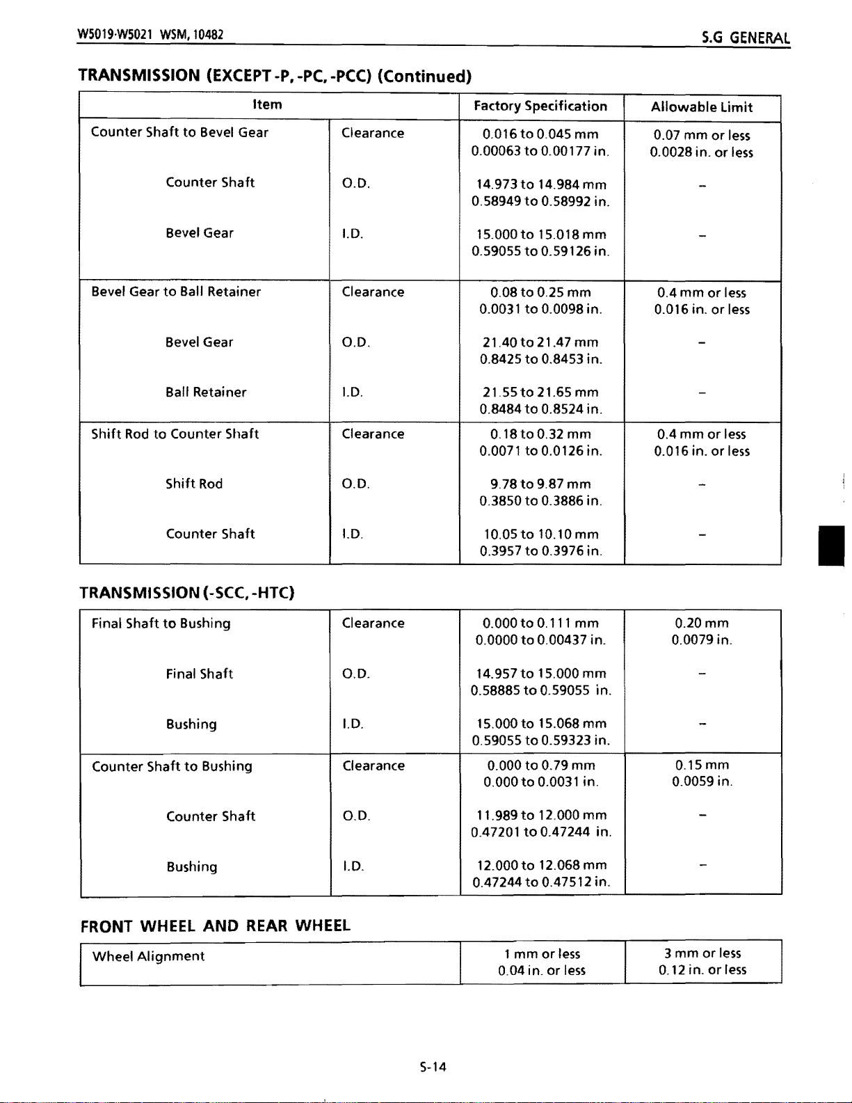
WS019WS021
WSM,10482
S.G
GENERAL
TRANSMISSION (EXCEPT -P, -PC. -PCC)
Item
Counter Shaft
Bevel Gear
Rod
Shift
to
Bevel Gear
Counter Shaft
Bevel Gear
to
Ball Retainer
Bevel Gear
Ball Retainer
to
Counter Shaft
Clearance
0.0.
1.0.
Clearance
0.0.
1.0.
Clearance
(Continued)
Factory Specification
to
0.045
0.016
0.00063
14.973
0.58949
15.000
0.59055
0.0031
0.8425
0.8484
0.0071
to
to
to
to
to
0.08
to
to
21.40to
to
21.55to21.65mm
to
0.18
to
to
mm
0.00177 in.
14.984 mm
0.58992 in.
15.018mm
0.59126 in.
0.25 mm 0.4 mm
0.0098 in.
21.47
mm
0.8453 in.
0.8524 in.
0.32 mm 0.4 mm
0.0126 in.
Allowable
0.07
mm
0.0028 in.
-
-
or
0.016 in.
-
-
or
0.016 in.
limit
or
or
or
or
less
less
less
less
less
less
Shift
Rod
Counter Shaft
TRANSMISSION (-SCC, -HTC)
Final Shaft
Counter Shaft
to
Bushing
Final Shaft
Bushing
to
Bushing
Counter Shaft
Bushing
0.0.
1.0.
Clearance 0.000
0.0.
1.0.
Clearance
0.0.
1.0.
9.78
0.3850
10.05to
0.3957
0.0000
14.957
0.58885
15.000
0.59055
0.000
O.OOOto
11.989to 12.000 mm
0.47201
12.000to 12.068mm
0.47244
to
9.87 mm
to
0.3886 in.
10.10mm
to
0.3976 in.
to
0.111 mm
to
0.00437 in.
to
15.000
to
0.59055 in.
to
15.068 mm
to
0.59323 in.
to
0.79
0.0031 in.
to
0.47244 in.
to
0.47512 in.
mm
mm
-
-
•
0.20mm
0.0079 in.
-
-
0.15 mm
0.0059 in.
-
-
FRONT WHEEL
Wheel
Alignment
AND
REAR
WHEEL
S-14
1
mm
0.04 in.
or
or
less
less
3 mm
0.12 in.
or
or
less
less
Page 46

S.G
GENERAL
HANDLE AND DISCHARGE GUARD
W5019W5021 WSM,10482
Mower
(Exccept
Drive Clutch
(Except
Blade Clutch Lever
-P,
-P,
-T)
lever
-PC,
-PCC)
Item
Total Travel
Distance
Total Travel (L2)
Distance
(12)
(12-L1)
(L2-L1)
Factory Specification
(-PC.
-PCC) 165
-SC,
-SCC
-SCE
TcE
(-TC,-
-HTC
CC.
-Pce)
-SC,
-SCC
-SCE
t-TC,-TcEl138to142mm
-HTC
90to97
3.54
86
3.39
to
148
5.43
3.82 in.
95 mm
3.74 in.
175 mm
to
6.89 in.
to
6.
to
152
to
5.98 in.
to
5.59 in.
mm
lOin.
6.50
l14Oto155mm
5.51
5.83
to
to
to
mm
Allowable
-
-
-
-
Limit
5-15
Page 47

W5019·W5021
{Gl
CA.R.A.CT(;'R.'ST'QU~S
WSM,10481
DE.TA\LUiES
ET REGLAGES
S.G
GENERALITES
CORPS
Jeu
Queue de soupape a
soupape
(Admission)
(Echappement)
Siege de soupape
Ressort de soupape
Chemise de cylindre
DU
MOTEUR
des
soupapes (il froid)
Queue de soupape 5,448 a5,460
Guide de soupape -
Queue de soupape
Guide de soupape
Article
guide
de
Jeu
D.E.
D.L
Jeu
D.E.
D.L
largeur
contact
longueur
D.1.
de
libre
Valeur
de
reference
a0,08
0,02
0,040 a0,064
5,500 a5,512 mm
0,060 a 0,084 mm
5,428 a 5,440 mm
5,500 a5,512 mm
0,6aO,8mm
33,0 a 33,5
61,OOa61,02mm 61,12
mm
mm
mm
mm
limite
0,1
0,1
1,3mm
32,5mm
de service
-
mm
-
mm
-
mm
Sur-dimension 61,25 a61,27 mm 61,37
Jupe de piston
Sur-dimension
logement
Axe de piston
Segment coup de feu
Segment d'etancheite
Segment
Segment coup de feu dans la gorge
du
piston
Segment
du
piston
Segment
piston
Segment coup de feu
Segment d'etancheite
Segment
d'axe de piston
radeur
d'
etancheite dans la gorge
radeur
radeur
dans la gorge du
D.1.
(0,25
D.1.
(0,50
D.E.
D.E.
(0,25
D.E.
(0,50
D.E.
Epaisseur
Epaisseur
Jeu
Jeu
a la coupe
OS)
OS)
OS)
OS)
mm
61,50 a 61,52 mm 61,62 mm
60,95 a 60,97
61,20a61,llmm
61,45 a61,47
13,009 a 13,017mm
13,000 a13,005
1,47 a 1,49 mm
2,47 a 2,49
it 0,06
0,02
0,20 a0,40
mm
mm
mm
mm
mm
mm
60,85mm
61,10
mm
61,35mm
t3,04mm
ll,96mm
mm
1,45
2,45 mm
0,1
mm
O,9mm
5-16
Page 48

S.G
GENERALITES
TRANSMISSION (-SCC, -HTC)
W5019W5021
WSM,10482
Arbre
de sortie
Arbre
de renvoi
ROUE
AVANT
Alignement
POIGNEE
Levier
d'embrayage
(sauf
-P,
Article
et
bague
Arbre
de
sortie
Bague
et
bague
Arbre
de
renvoi
la
que
lame
Engrenage coni
ET
ROUE ARRIERE
de roue 1
ET
GARDE D'EJECTION
de
-T)
Jeu
D.E.
D.1.
Jeu
D.E.
D.1.
Course
Distance
totale
(L2-L1)
(L2)
Valeur de reference
0,000 a 0,111
14,957 a15,000
15,000 a15,068
0,000 a 0,079
11,989 a 12,000
12,000 a12,068
mm
ou moins
CC,-PCCl
-SC,
-SCC
-SCE
(-TC,
-TCE)
-HTC
(-PC.
-PCC)
-SC,
-SCC
-SCE
165a175mm
140 a 155
148a152mm
mm
mm
mm
mm
mm
mm
mm
Limite
O,2mm
O,15mm
mm
3
de service
-
-
-
-
ou moins
-
-
Levier
d'embrayage
d'
entrainement
(sauf
-P,
-PC,
-PCC)
Course
Distance
totale
(L2)
(L2-L1)
(-TC,
-HTC
-TCE)
90a
86a95
138a
97
mm
mm
142
mm
-
-
S-19
Page 49

WS019WS021
WSM,10482
S.G
GENERALITES
EMBRAYAGE
lame
lame
a carter
Hauteur de coupe
hauteur
Dispositif
porte-lame
Garniture de porte-lame Profondeur 1,Omm O,5mm
Ressort d'embrayage
de coupe gauche
TRANSMISSION
Pignon conique a
transmission (Droit)
DE
LA
LAME
Article
d'outil
de commande B a
de coupe
droite
a
(SAUF
trou
de carter de
Pignon coni que
Trou
de carter de
transmission (Droit)
-P,
ET
-PC,
LAME
Jeu
"extremite
Jeu
Difference
Jeu
longueur
-pee)
Jeu
D.E.
D.1.
de
libre
Valeur de reference
mmou
3
moins
3a7mm
-
1,0
mm ou plus
28,Omm
0,013 a 0,037 mm
9,978 a 9,987
10,000 a 10,015 mm
mm
Limite
27,S
0,1
mm
de service
3mm
-
-
-
mm
ou
-
-
moins
de renvoi a
Arbre
engrenage
Engrenage conique
anneau de retenue
Tige
de selection aarbre de renvoi
coni que
de renvoi
Arbre
Engrenage conique
a
abilles
Engrenage coni que
Anneau
billes
Tige
Arbre
de retenue a
de selection
de
renvoi
Jeu
D.E.
D.1.
Jeu
D.E.
D.1.
Jeu
D.E.
D.1.
a0,045
0,016
14,973 a14,984 mm
15,000
a15,018 mm
0,08
a0,25
21,40 a21,47 mm
a21,65 mm
21,55
0,18 a 0,32 mm
a9,87
9,78
10,05 a 10,10 mm
mm
mm
mm
0,07
mm
ou moins
-
-
0,4 mm ou moins
-
-
0,4 mm ou moins
-
-
Page 50

S.G
ALLGEMEINES
MOTORKORPER (Fortgesetzt)
WS019WS021
WSM,10481
Teil
Olabstreifring
Oberer Verdichtungsring und
Ringnut
Zweiter Verdichtungsring und
Ringnut
Olabstreifring und Ringnut
Oberer Verdichtungsring
Zweiter Verdichtungsring
Olabstreifring
Pleuelstangenkopfbohrung
Kurbelzapfen und
PleuelstangenfuBbohrung
Kurbelzapfen
PleuelstangenfuBbohrung
UntergroBen-Kurbelzapfen und
UntergroBenPleuelstangenfuBbohrung
Dicke
Spiel
Spalt
Innen-
durchmesser
Olspiel
AuBendurchmesser
Innendurchmesser
Olspiel
US,
(0,25
0,50
Werkdaten
2,47 bis 2,49 mm
0,02 bis 0,06 mm
0,20 bis 0,40 mm
13,015 bis 13,025 mm
0,015bisO,041 mm
25,475 bis 25,485 mm
25,500 bis 25,516 mm
0,015 bis
US)
0,041
mm
ZuUissiger
2,45 mm
0,1
0,9mm
13,07 mm
0,1
0,1
Grenzwert
mm
mm
-
-
mm
UntergroBenKurbelzapfen
UntergroBenPleuelstangen-
fuBbohrung
Pleuelstange
Kurbelzapfen
Kurbelwelle
Nocken (EinlaB und AuslaB)
auf
dem
AuBendurchmesser
US)
(0,25
AuBendurchmesser
US)
(0,50
Innen-
durchmesser
US)
(0,25
Innen-
durchmesser
US)
(0,50
Seitenspiel
Seitenspiel
Hohe 27,335 bis 27,365 mm
25,225 bis 25,235 mm
24,975 bis 24,985 mm
25,250 bis 25,266 mm
25,000 bis 25,016 mm
0,2 bis 0,9 mm
-
-
-
-
-
1,5mm
0,2mm
27,15 mm
S-21
Page 51

WS019WS021 WSM,10481
[6]
WARTUNGSDATEN
MOTORKORPER
S.G
ALLGEMEINES
Tei!
Ventilspiel (Kalt)
Ventilschaft und VentilfOhrung
(EinlaBventilseite)
Venti
Ischaft
VentilfOhrung
(AuslaBventilseite)
Ventilschaft
VentilfOhrung
Ventilsitz
Ventilfeder
laufbOchse
Spiel
Au Bendurchmesser
Innen-
durchmesser
Spiel
Au Ben-
durchmesser
Innendurchmesser
Breite
Freie
lange
Innendurchmesser
Werkdaten
0,02 bis 0,08
0,040 bis 0,064 mm
5,448 bis 5,460 mm
5,500 bis 5,512 mm
0,060 bis 0,084
5,428 bis 5,440
5,500 bis 5,512
0,6 bis 0,8
33,0 bis
61,00 bis 61,02 mm
33,S
mm
mm
mm
mm
mm
mm
Zulassiger
0,1
0,1
1,3mm
32,5
61,12mm
Grenzwert
-
mm
-
-
mm
-
-
mm
ObergroBe
Kolbenschaft
ObergroBe
Kol benbolzenbohru ng
Kol benbol zen
Oberer Verdichtungsring
Zweiter Verdichtungsring
Innendurchmesser
(0,25
OS)
Innendurchmesser
OS)
(0,50
AuBen-
durchmesser
AuBendurchmesser
OS)
(0,25
AuBendurchmesser
(0,50
OS)
Innen-
durchmesser
AuBen-
durchmesser
Dicke
61,25bis61,27mm
61,50bis61,52mm
60,95 bis 60,97
61,20 bis 61,22
61,45bis61,47mm
13,009 bis 13,017
13,000 bis 13,005
1,47 bis 1,49
mm
mm
mm
mm
mm
61,37 mm
61,62 mm
60,85mm
61,10
mm
61,35mm
13,04
mm
12,96 mm
1,45
mm
•
5-20
Page 52

S.G
GENERALITES
W5019W5021
WSM.10481
CORPS
Pied de bielle
Maneton
Maneton sous-dimensionne a
tete
Bielle
DU
MOTEUR
a
tete
de bielle
Maneton
Tete de bielle
de bielle sous-dimensionnee
Maneton
dimensionne
Tete de bielle
sous-dimensionnee
ilebrequin
(Suit)
Article
sous-
Valeur de reference
0.1.
Jeu
de marche
D.E.
0.1.
Jeu
de marche
(0,25
US, 0,50 US)
D.E.
(0,25 US)
D.E.
(0,50 US)
0.1. (0,25 US)
(0,50 US)
0.1.
Jeu
lateral
Jeu
lateral -
13,015
25,475 a25,485 mm
25,500 a25,516
25,225 a 25,235 mm
24,975 it 24,985 mm
25,250 a25,266 mm
25,000 a 25,016 mm
a13,025 mm
a
0,041
0,015
O,015aO,041 mm
0,2
a
mm
mm
0,9mm
Limite de service
13,07 mm
0,1
mm
-
0,1
mm
-
-
-
-
1,5mm
0,2mm
Cames d'admission
d'
echappement
et
SYSTEME 0'ALLUMAGE
Bougie d'allumage
Noyau du bloc de commande
d'allumage
magnetique
Bobine
(Essai
DEMARREUR
Balai
Commutateur
Commutateur et arbre de
a
aimant
d'allumage
simplifie avec un ohm metre)
Enroulement primaire
Enroulement
secondaire
du
(-SCE, -
volant
TCE)
induit
Hauteur 27,335
Ecartement des
electrodes
Jeu
Resistance
Resistance
Longueur
D.E.
Resistance
0,7
Environ 0,6
Environ 12,6 kU
a27,365
a0,8 mm
0,5mm
mm
Q
27,15mm
-
-
-
3,5mm
21
mm
0,1
Q ou plus
SYSTEME
Bobine de charge
DE
CHARGE
(-SCE,
-TCE)
Resistance
S-17
O,4U ±
15%
Page 53

WS019WS021
WSM,10482
ZUNOANLAGE
S.G
ALLGEMEINES
Tei!
ZOndkerze
ZOndeinheitskern und
Rotormagnet
Spulenprobe (Vereinfachte Probe
mit
einem Ohmmeter)
Primarspulen
Sekundarspulen
ANLASSER
BOrste
Kommutator
Kommutator
LAOESYSTEM
(-SCE, -
zu
TCE)
Ankerwellen
(-SCE,-TCE)
I ladespule
MESSERKUPPLUNG
UNO
Widerstand
AD.
Widerstand
MESSER
Elektrodenabstand
Zwischenraum
Widerstand
lange
Widerstand
Werkdaten
0,7 bis 0,8 mm
0,5mm
Ca.
0,6 Q
Ca.
12,6 kQ
-
-
O,4n
±
15%
Zulassiger
3,5mm
21
0/1
MQ oder mehr
Grenzwert
-
-
-
-
mm
Messer Endspiel 3 mm oder
Messer und Messergehause Zwischenraum 3 bis 7
Rechte Schnitthohe und
Linke Schnitthohe
Betatigungsglied B und
Messerhalter
Messerhalterbelag
Kupplungsfeder
GETRIEBE
Kegelritzel und
loch
Vorgelegewelle und Kegelrad
(AUBER
im
GetriebegeMuse
-P,
-PC,
-pcq
(RH)
Unterschied
Zwischenraum
der
Tiefe
Freie Lange 28,Omm
Zwischenraum
AuBendurchmesser
Innen-
durchmesser
Zwischenraum
Riefe 1,Omm
1,0
mm
0,013 bis 0,037 mm
9,978 bis 9,987
10/000 bis 10,015
0,016 bis 0,045 mm
weniger
mm
-
oder mehr
mm
mm
-
-
3mm
0/5mm
27/5mm
0,1
mm
oder
weniger
-
-
0,07 mm oder
weniger
-
I
I
I
Au Ben-
durchmesser
Innen-
durchmesser
S-22
14,973 bis 14,984 mm
15,000 bis 15,018 mm
-
Page 54

S.G
ALLGEMEINES
W5019W5021 WSM,10482
GETRIEBE
Kegelrad und Kugelkafig
Schaltstab und Vorgelegewelle
GETRIEB
Endwelle zu Buchse
(AUBER -P, -PC, -peC)
leil
(-SeC, -HTC)
(Fortgesetzt)
Zwischenraum
AuBendurchmesser
Innendurchmesser
Zwischenraum
AuBendurchmesser
Innendurchmesser
Spiel
Werkdaten
bis 0,25
0,08
21,40bis21,47mm
21,55bis21,65mm
0,18 bis 0,32 mm
9,78 bis 9,87
10,05 bis 10,10 mm
0,000 bis 0,111
mm
mm
mm
Zulassiger
Grenzwert
0,4 mm oder
weniger
-
-
0,4 mm oder
weniger
-
-
0,20mm
Endwelle
Buchse
Vorgelegewelle zu Buchse
Vorgelegewelle
Buchse
A.D.
1.0.
Spiel
A.D.
1.0.
14,957 bis 15,000
15,000 bis 15,068 mm
0,000 bis 0,079
11,989 bis 12,000
12,000 bis 12,068
VOROERRAO UNO HINTERRAO
Radausrichtung 1
HANOGRIFF UNO AUSWURFSCHUTZ
Messerkupplungshebel
(auBer
-P,
-T)
Gesamthub
Entfernung
(L2-L1)
(L2)
(-PC,
-SCC,
(-lC,
-HTC
(-PC,
-SCC,
mm
mm
mm
mm
mm
oder
weniger weniger
165
-pcc,
-SC)
-SCE
-TCE)
-PCC, -SC
140 bis
-SCE
)
bis
17Smm
155
mm
148
bis
lS2mm
3
-
-
0,15 mm
-
-
mm
oder
-
-
Antriebskupplungshebel
(auBer
-P,
-PC,
-PCC)
Gesamthub
Entfernung
(L2-L
1)
(L2)
S-23
(-TC,
-HTC
-TCE)
138
90bis97
86 bis9S mm
bis
mm
142
mm
-
-
Page 55

W5019·W5021 WSM,10481
[7] TIGHTENING TORQUES
(1)
Tightening
Torques
for
Important
Screws, Bolts
and
Nuts
S.G
GENERAL
Section
Engine
and
Blade
Handle
(2)
Tightening
Screws, bolts and nuts
tightened
~
Nominal \
Diameter
according
Grade
Unit \
Torques
Item
Drain plug
Spark plug
Governor lever
Lock
nut
mounting
Rotor
Cylinder
Crankcase cover
Connecting rod screw
Float
Main
Main nozzle (Carburetor)
Blade
Handle lock grip
head
chamber
jet
mounting
for
whose
to
the
table
*(
N·m
mounting
(Rocker arm)
nut
screw
mounting
mounting
(Carburetor)
screw
General Use Screws, Bolts and
tightening
below.
or
No-grade
Qor@
kgf·m ft-Ibs
4T
screw
screw
screw
torques
)
are
N·m
19.6to
58.8
24.5
13.7to
49.0
29.4
9.8t024.5
to
11.8
6.9
to
12.7
7.8
to
68.6
to
32.4
9.8to
19.6
6.9
0.69
2.0
to
58.8
8.34
14.7
kgfom
2.0t03.0
1.0t02.5
0.7
to
1.2
0.8to
1.3
6.0t07.0
to
3.3
2.5
to
1.5
1.0
to
2.0
1.4
0.7
0.07
0.2
5.0to
6.0
0.85
14.5
43.4
18.1
10.1
36.2
Nuts
not
specified in this Workshop Manual should
7T
N·m
* (
())
kgf·m
)
ft-Ibs
7.2
5.1
5.8
7.2
0.51
6.15
ft-Ibs
to
to
to
to
to
to
to
to
5.1
1.4
to
21.7
18.1
8.7
9.4
50.6
23.9
10.8
14.5
43.4
be
I
M6
M8
M10
M12
M14
M16
M18
M20
* The figures
7.85
17.65
39.23
62.76
107.9
166.7
245.2
333.4
on
the
t09.32
to
20.59 1.80
to
45.
to
72.57 6.40
to
125.5 11.0
to
191.2
to
284.4
to
392.3
table
0.80
11
4.00
17.0to
25.0to
34.0t040.0
above are indicated
to
0.95 5.79
to
2.10 13.02
to
4.60
to
7.40 . 46.29
to
12.8 .56
19.5 123.0
29.0
28.93
180.8
245.9
the
top
to
6.87 9.81
to
15.19 23.54
to
33.27 48.05
to
53.52 77.47
to
92.58
to
141.0
to
209.8 274.6
to
289.3
of
screw
to
to
to
to
123.6to
196.1
to
to
367.7
to
or
bolt.
11.28 1.00
27.46
55.90
90.22
147.1
225.6
318.7
431.5
2.40to
4.90
7.90
12.6to15.0
20.0to
28.0
37.5
to
1.15 7.23
2.80 17.36
to
5.70
to
9.20 57.14
23.0
to
32.5 202.5
to
44.0
to
to
35.44
to
to
91.1
to
144.7to
to
271.2
to
8.32
20.25
41.23
66.54
108.5
166.4
235.1
318.3
5-24
Page 56

S.G
GENERALITES
[7]
COUPLES
(1)
Couples
de
serrage
DE
SERRAGE
pour
vis, boulons
et
ecrous
d'une
W5019W5021 WSM,10481
utilisation particuliere
Section
Moteur
Lame
et
poignee
(2) Couples
Les
vis,
boulons
de
serrage
et
Bouchon
Bougie d'allumage
Vis
Contre-ecrou (Culbuteur)
Ecrou de
Vis
Vis de
Vis
Vis
Gicleur (Carburateur)
Gicleur principal (Carburateur)
Vis
Prise
pour
ecrous
dont
de vidange
de
fixation
fixation
de
fixation
fixation
de
fixation
de
fixation
de
fixation
de verrouillage de poignee
vis, boulons
les
couples de serrage ne sont
Article
du bras de regulateur
du volant magnetique
de
culasse
de couvercle du carter
du chapeau de bielle
de cuve a niveau constant
de la lame
etre serres selon les valeurs du tableau ci-dessous.
Grade
K'
Diametre
nominal
Unite \
~
*(
N·m
Sans
Qou@
grade ou
moteur
et
ecrous d'utilisation
pas
specifies dans Ie manuel
4T
)
kgf·m N·m
N'm
19,6
is
9,8 a 24,5
6,9 a 11,8
7,8i112,7
58,8a
24,5 a 32,4
9,8a
13,7 a 19,6
6,9
0,69
2,0
49,Oa 58,8
8,34
genera
*(
29,4
68,6
14,7
Ie
0
7T
kgf'm
2,Oa 3,0
1,0 a 2,5
0,7 a 1,2
0,8 a
6,0 a 7,0
2,5 a 3,3
1,Oa 1,5
1,4 a 2,0
0,7
0,07
0,2
5,Oa 6,0
0,85
d'atelier
)
kgf·m
1,3
doivent
M6
M8
M10
M12
M14
M16
M18
M20
*
Les
chiffres du tableau
7,85 a 9,32 0,80 a 0,95
17,65 a 20,59 1,80 a 2,10
39,23 a 45,11
62,76 a 72,57
107,9a
166,7 a 191,2 17,0 a 19,5
245,2 a 284,4 25,0 a 29,0
333,4 a 392,3
ci-dessus
125,5 11,Oa 12,8
correspondent ala partie superieure
4,00a4,60
6,40 a 7,40 77,47 a 90,22 7,90 a 9,20
34,0 a 40,0
9,81al1,28
23,54 a 27,46
48,05 a 55,90
123,6a
196,1 a 225,6 20,Oa 23,0
274,6 a 318,7
367,7 a 431,5 37,5 a 44,0
des
vis
147,1
et
des boulons.
1,00 a 1,15
2,40 a 2,80
4,90a
5,70
is
15,0
12,6
28,0 a 32,5
I
S-25
Page 57

WS019WS021
WSM,10481
[7] ANZUGSDREHMOMENTE
S.G
ALLGEMEINE5
(1) Anzugsdrehmomente
Kapitel
Motor
Messer und
Handgriff
(2) Anzugsdrehmomente
Wenn
der
~
die
Anzugsdrehmomente
rachstehenden Tabelle
Klassifikation Nicht klassifiziert
fur
wichtige Schrauben, Bolzen und
AblaBschraube
ZOndkerze
Drehzahl reglerhebel-Montageschr
Gegenmutter
Rotor-Montagemutter
Zylinderkopfschraube
Kurbelgehausedeckel-Montageschraube
Pleuelstangenschraube
Schwimmerkammer-Montageschraube
HauptdOse (Vergaser)
PrimardOse (Vergaser)
Messer-Montageschraube
Lenkergriff
fur
allgemeine Schrauben, Bolzen und
nicht
angezogen.
lei!
(Kipphebel)
angegeben
oder
sind,
41
au
be
werden
Muttern
N'm
19,6 bis 29,4
9,8 bis 24,S
6,9 bis 11,8
7,8bis
58,8 bis 68,6
24,5 bis 32,4
9,8 bis 14,7
13,7 bis 19,6
49,0 bis 58,8
12,7
6,9
0,69
2,0
8,34
mkp
2,0 bis 3,0
1,0 bis 2,5
0,7 bis
0,8 bis
6,0 bis 7,0
2,5 bis 3,3
I,Obisl,5
1,4 bis 2,0
5,0 bis 6,0
1,2
1,3
0,7
0,07
0,2
0,85
Muttern
die Schrauben, Bolzen und Muttern gemaB
7T
Einheit
Nenndurchmesser
M6
M8
Ml0
M12
M14
M16
M18
M20
*
Die
in
angegeben.
der
~
~
Tabelle
*(
N·m
7,85 bis 9,32
17,65 bis 20,59
39,23 bis 45,11
62,76 bis 72,57
107,9 bis 125,5
166,7 bis 191,2
245,2 bis 284,4
333,4 bis 392,3
verwendeten
o
oder
0
Bezeichnungen
)
mkp
0,80 bis 0,95
1,80 bis 2,10
4,00 bis 4,60
6,40 bis 7,40
11,0 bis 12,8
17,0 bis 19,5
25,0 bis 29,0
34,0 bis 40,0
sind
auf
N·m
9,81 bis 11,28
23,54 bis 27,46
48,05 bis 55,90
77,47 bis 90,22
123,6 bis
196,1 bis 225,6
274,6bis318,7
367,7 bis431,5
den
Kopfen
*(
147,1
der
Schrauben
())
)
mkp
1,00 bis 1,15
2,40 bis 2,80
4,90 bis 5,70
7,90 bis 9,20
12,6 bis 15,0
20,0 bis 23,0
28,0 bis 32,S
37,5 bis 44,0
und
Muttern
I
S-26
Page 58

5.G
GENERAL I GENERAlITE5
WS019WS021 WSM,10482
[8] MAINTENANCE CHECK
"\0
~e~p
the
,machine w,orking
periodic inspection and maintenance. Check
Service Interval
Each
use
(Daily)
month
First
hours
Every 3 months
hours
Every 6 months
hours
Every year
or
initial
or
or
or
300 hours
20
50
100
LIST
in
good
• Check
• Check
•
•
• Retighten
• Check
• Change
• Clean
•
•
•
•
• Adjust
• Adjust
•
•
• Check
• Check
the
the
Check
the
Check
the
Change
Clean and readjust
Clean
the
Adjust
Clean
the
Replace
condition
the
fuel level
engine oil level
air cleaner element
and clean
the
the
mower
the
air cleaner element
the
fuel
the
the
the
fuel tank
the
the
valve clearance
the
mower
as
well
as
following
blade
engine
engine oil
filter
throttle
mower
drive clutch lever (Except
fuel pipe
points before
Check Points
the
grass
mounting
blade
oil
the
spark plug
lever
blade clutch lever (Except
blade
dutch
to
avoid any
use.
catcher bag
screw
-P,
(Except
-PC,
-P,
trouble
-P,
-pcq
-T)
-T)
or
accident, carry
Reference
Page
5-29
5-31
out
5-29
-
5-31
5-33
5-33
5-35
5-35
5-35
5-35
5-37
5-39
5-39
5-41
5-41
5-41
5-41
[8] TABLEAU
Pour
maintenir
periodiquement Ie contrOle
Peri odes
Chaque utilisation
(Journellement)
Premier mois ou
20
heures
Toutes les 3 mois
toutes les
Toutes les 6 mois ou
toutes les100 heures
Tous les ans ou toutes les
300 heures
50
DES
la machine en bon
d'entretion
premili1!res
ou
heures
PERIODICITES D'ENTRETIEN
etat
de
et
I'entretien.
•
Verifier
Verifier
•
• Verifier
Verifier
•
Resserrer les vis
•
• Verifier la lame
• Changer
• Nettoyer
• Changer
Nettoyer
•
Nettoyer Ie
•
• Regier Ie levier
Regier Ie levier d'embrayage de la lame (sauf -P,-T)
•
Regier Ie levier d'embrayage
•
(sauf
Nettoyer
•
Remplacer Ie tuyau
•
Verifier
•
Verifier
•
fonctionnement
Verifier
-P,
les points suivants avant utilisation.
Points
Ie niveau de carburant
Ie niveau
I'element
et
nettoyer
I'huile
I'elementdu
I'huile
et
-PC,
Ie
Ie jeu des soupapes
I'embrayage de la lame (sauf
d'huile
du
Ie
de
fixation
moteur
moteur
reajuster la bougie
filtre
acarburant
d'
accelerateur
-PCC)
reservoir acarburant
d'alimentation
et
;!I
verifier
moteur
filtre
aair
sac
aherbe
de la lame 5-32
filtre aair
eviter
tout
accident ou incident,
d'allumage
d'entrainement
de carburant
-P,
-T)
effectuer
Voir
page
5-30
5-30
5-32
-
5-34
5-34
5-36
5-36
5-36
5-36
5-38
5-40
5-40
5-42
5-42
5-42
5-42
5-27
Page 59

WS019·WS021
[8]
WARTUNGS-CHECKLISTE
Um
diesen regelmaBig OberprOfen und warten.
WSM,10482
den Maher
in
gutem Betriebszustand
zu
halten und um Unfalle oder BetriebsstOrungen
S.G
AllGEMEINES
zu
vermeiden,
Wartungsi ntervall
NachjederVerwendung
(Taglich)
Nach 1
den ersten
Aile 3 Monate oder aile
5tunden
Aile 6 Monate oder aile
1005tunden • ZOndkerze reinigen und Elektrodenabstand nachstellen
Jahrlich oder aile
5tunden
Monat
oder nach
20
5tunden
50
300
• Kraftstoffstand OberprOfen
MotorOlstand Oberprofen
•
Luftfiltereinsatz OberprOfen
•
Grassauffangsack oberprOfen und reinigen
•
Messer-Montageschrauben anziehen
•
• Messer OberprOfen
• MotorOI wechseln
• Luftfiltereinsatz reinigen
Motorol
•
• Kraftstoffilter reinigen
• Drosselklappenhebel einstellen
• Messerkupplungshebel einstellen (auBer
• Antriebskupplungshebel einstellen (auBer
Kraftstoffbehalter reinigen
•
Kraftstoffrohre auswechseln
•
• Ventilspiel oberprOfen
• Messerkupplung OberprOfen (auBer
wechseln
Prufpunkte
-P, -T)
-P,
-P,
-T)
-PC,
-PCC)
Bezugsseite
5-30
5-30
5-32
-
5-32
5-34
5-34
5-36
5-36
5-36
5-36
5-3B
5-40
5-40
5-42
5-42
5-42
5-42
•
5-28
Page 60

S.G
GENERAL
[9]
CHECK
W5019W5021 WSM.10481
AND MAINTENANCE
(1) Check Points
(a
(b
of
Each Use
or
Daily
Checking Fuel Level
1.
Place
the
engine).
2.
To check
(1).
3,
Check
to
4.
If
necessary. supply
proper level
machine
the
fuel level, remove the fuel
see
that
is
on a flat
there
the
reached.
is
sufficient fuel.
specified
A CAUTION
the
• Before refueling, stop
cools
down.
• Wipe up any
• IMPORTANT
Use
•
(1) Tank Cap
Checking Engine Oil
the
Refer
to
1.
Place
engine).
2.
Check
wait
at
3.
Unscrew the oil level dipstick (1),
then screw
4.
Remove
level
is
5.
If
the level
specified level
spiltfuel
specified fuel.
"LUBRICANTS AND FUEL",
level
the
machi ne on a
the oil level before starting the engine
least 5 minutes
it
in
again well.
the
gauge again and check
between
is
too
is
the
low,
reached .
engine and
immediately
after
upper (a) and
supply fresh oil
surface (level
fuel
.
(See
flat
surface (level
stopping
lower
wait
the
wipe
that
the
tank
cap
until
the
until
page
S·3)
the
engine.
it
clean,
the
(b) Iim'lts.
until
the
it
or
oil
0617F017
• IMPORTANT
•
Use
the specified engine oil.
to
Refer
•
When
viscosity
Never
(1) Oil Level DipstIck
(a) Upper
(b)
Lower
5-29
"LUBRICANTS AND FUEL".
using
mix
Limit
limit
from
two
new
oil
of a different
the
previous one, drain all used oil.
different
types
of
(See
oil.
page
maker
S·3)
or
Page 61

WS019WS021
WSM,10481
S.G
GENERALITES I ALLGEMEINE5
[9] VERIFICATION
ET
ENTRETIEN
(1) Points averifier toutes chaque utilisation
ou journellement
Verification
1.
Placer la machine sur
moteur
2.
Pour verifier Ie niveau de carburant, deposer Ie
bouchon du reservoir de carburant (1).
3.
Verifier
4.
Sinon, faire
jusqu'i\
A
ATTENTION
•
Avant
attendre
• Essuyer immediatement
• IMPORTANT
• Utiliser I'essence specifiee.
Se
(Voir page
(1) Bouthon de reservoir
du
niveau de carburant
un
sol
de niveau)
si
Ie
niveau de carburant est correct.
I'appoint
ce
qu'il
atteigne la bonne quantite.
de
refaire
qu'il
se
reporter a "LUBRIFIANTS
S-4)
avec
Ie
plein,
refroidisse.
tout
plat.
du carburant specifie
arreter
carburant renverse.
ET
(Mettre
Ie
moteur
CARBURANT".
Ie
et
[9] OBERPROFUNG
UNO
WARTUNG
(1) Nach jeder Verwendung oder taglich
OberprOfende Punkte
Oberpriifen des Kraftstoffstands
1.
Den Maher
(Der
befinden)
2.
Zum
KraftstofftankverschluB
3.
NachprOfen, ob der Kraftstoffstand richtig ist.
4.
1st
dies
bis zum richigen Stand nachfOllen.
A
VORSICHT
• Vor dem Nachtanken
abkiihlen lassen.
• Verschutteten
.WICHTIG
• Nur den vorgeschriebenen
Siehe
KRAFTSTOFF".
(1) Kraftstoffta
auf
einer ebenen Oberflache abstellen.
Motor
OberprOfen
muB sich
nicht
der
Kraftstoff
Abschnitt
(Siehe Seite
n k verschlu3
in
waagerechter
des
Kraftstoffstands
(1)
entfernen.
Fall, vorgeschriebenen Krafstoff
den
Motor
sofort
Kraftstoff
"SCHMIERMITTEL
S-4)
abstellen
aufwischen .
verwende.
zu
Lage
den
und
UND
Verification
1.
Placer la machine sur un sol
moteur
2.
Verifier
moteur
I'
avoir arrt!te.
3.
Devisser la jauge de niveau
la visser suffisamment.
4.
Redeposer la jauge pour voir
trouve entre
(b).
5.
Si
Ie niveau est
fraiche jusqu'au niveau specifie.
• IMPORTANT
• Utiliser
Se
(Voir page
•
En
viscosite
toute
d'huile.
(1) Jauge de niveau d'huile
(a)
Limite superieure de niveau
(b) Limite inferieure de niveau
du
niveau
de niveau)
Ie
niveau
en marche ou au moins 5 minutes apres
les
I'huile
reporter a "LUBRIFIANTS
S-4)
cas
d'utilisation
differente
I'huile
usee. Ne jamais melanger deux types
d'huile
d'huile
limites superieure (a)
trop
bas,
moteur
specifiee.
d'huile
de la precedente,
d'huile
d'huile
moteur
plat.
avant
d'huile
si
Ie
faire
I'appoint
ET
de
(Mettre
de
mettre
(1), I'essuyer
niveau
d'huile
et
inferieure
d'huile
CARBURANT".
marque
ou
vidanger
OberprUfen des Motorolstands
Ie
1.
Ie
2.
et
3.
se
4.
5.
.WICHTIG
•
de
•
(1) OlmeBstab
(a) Obere Grenze
(b) Untere Grenze
Den Maher
(Der
befinden)
Den Olstand vor dem Anlassen
mindestens 5
Motors OberprOfen.
Den OlmeBstab (1) abschrauben, sauber wischen
und wieder
Den
nachzuprOfen, ob
oberen (a) und unteren (b) Grenzmarke befindet.
Wenn der Stand
vorgeschriebenen Stand nachfOllen .
Das
vorgeschriebene
Siehe
KRAFTSTOFF".
Wenn
anderer ViskosiUit
ganz
Olsorten mischen.
auf
Motor
OlmeBstab
ablassen.
muB sich
weit
Abschnitt
01
eines
des
des
einer ebenen Oberflache abstellen.
in
waagerechter
des
Minuten
genug hineinschrauben.
zu
(Siehe Seite
anderen
Olstands
Olstands
nach dem
wieder
sich
der
niedrig ist, frisches
Motorol
"SCHMIERMITTEL
verwendet
Niemals
entfernen,
Olstand zwischen
verwenden.
S-4)
Herstellers
wird,
zwei
Motors
Abstellen
das
verschiedene
01
bis zum
oder
alte
Lage
bzw.
des
um
der
UND
mit
01
•
S-30
Page 62

S.G
GENERAL
W5019W5021 WSM.10481
0617F018
0617F019
Checking
1.
Unscrew
Air
Cleaner Element
two
wing
cleaner cover (2) and
urethane elements.
2.
Paper element (4) :
the
dust
Blow
off
compressed air. Replace
one
if
it
is
excessively dirty.
3.
Urethane element
the
and
element
dry
it
well.
Mounting
Wash
Rinse
(1) Wing Screw
(2) Air Cleaner Cover
Retightening Blade
A CAUTION
To
avoid injury, always handle
•
with
care.
1.
Close
the
fuel
filter
2.
Turn
the
machine sideways
always upward.
3.
Wedge a block
blade and
will
safely hold
4.
Retighten
specified torque.
5.
If
the
blade
replace them.
of
the
housing
the
the
blade
mounting
screws (1),
take
the
element from inside
the
(3)
:
with
liquid detergent.
(3) Urethane Element
(4) Paper Element
remove
out
element
Screw
the
cock.
with
wood
(1)
securely between one
in
such
a position
blade.
mounting
screws (2)
screws are
the
paper
with a new
mower
the
muffler
worn
or
the
air
and
with
blade
side
that
to
the
broken,
it
Tigh~ning
torque
(l)
Block
of
Wood
Blade
mounting
screw
(2) Blade
49.0
to
5.0
to
6.0
36.2
to
Mounting
588
N'm
kgf·m
43.4 ft-Ibs
Screw
5-31
Page 63

WS019WS021
WSM,10481
S.G
GENERALITES I AllGEMEINES
Verification de I'element du
1.
Devisser les deux vis a
couvercle de
papier
2. Element en papier (4):
Souffler aI'air comprime la poussiere de I'element
par I'interieur. Remplacer I'element par un neuf
sin
est
trop
3.
Element en polyurethane (3):
Laver I'element avec un detergent liquide. Bien Ie
rincer
et
(1)
Vis
aailettes
(2) Couverde
Resserrage de la vis de
A
ATTENTION
• Pour eviter
lame avec precaution.
1.
Fermer
2.
Tourner lateralement la machine avec Ie cote du
pot
d'echappement toujours dirige
3.
Caler de
lame
et
risque la lame.
4.
Resserrer
specifie.
5.
Si
les
cassees,
Couple de
serrage lame
filtre
aair (2)
et
en polyurethane.
sale.
Ie faire secher.
du
filtre aair
d'etre
Ie
robinet du
fa~on
sOre
Ie carter de
les
vis
de fixation de la lame
vis de
fixation
les
remplacer.
Vis
de
fixation
filtre
aair
ailettes
et
(3) Element en polyurethane
(4) Element en papier
fixation
blesse,
manipuler
filtre
acarburant.
un bloc de bois (1)
fac;on
de
la lame sont
de la
(1),
sortir
les
de la lame
vers
qu'il
maintienne
49,0 a58,8 N'm
5,0
deposer
elements en
toujours
Ie haut.
entre
(2)
au
couple
usees
a6,0 kgf·m
Ie
la
la
sans
ou
Oberprufen der Luftfiltereinsatze
1.
Die beiden FIOgelschrauben (1) abschrauben, den
Luftfilterdeckel (2) entfernen und die Papier- und
U rethanei nsatze herausnehmen.
2.
Papiereinsatz (4):
Staub von der Innenseite
Einsatz wegblasen. Den Einsatz
neuen ersetzen, wenn dieser
aus
mit
zu
schmutzig ist.
Druckluft
durch
vom
einen
3. Urethaneinsatz (3):
Den
Einsatz
abwaschen. Den Einsatz
lassen.
(1) FIOgelschrauben
(2)
luftfilterdeckel
Wiederanziehen der Messer-Montageschraube
AVORSICHT
• Um eine Verletzung zu vermeiden, das Messer
stets vorsichtig handhaben.
1.
Den
Kraftstoffilterhahn schlieBen.
2.
Die Maschine
Schalldampferseite stets nach oben weist.
3.
Ein
HolzstUck (1) fest zwischen das Messer und
Gehause drucken,
wird.
4.
Die Messer-Montageschrauben
vorgeschriebene Anzugsdrehmoment anziehen.
5.
Wenn die Messer-Montageschrauben
oder abgebrochensind, diese auswechseln.
Anzugs· Messerdrehmoment
mit
einem flOssigen Reinigungsmittel
gut
abspulen und trocken
(3) Urethaneinsatz
(4) Papiereinsatz
auf
die
Seite kippen,
so
daB
das
Messer festgehalten
(2)
Montageschraube 5,0 bis 6,0
so
wieder
abgenutzt
49,0 bis 58,8 N'm
daB
auf
mkp
die
das
•
(1)
Bloc
de
bois
(2)
Vis
de
fixation
de la lame
(1) HolzstOck
(2) Messer-Montageschraube
S-32
Page 64
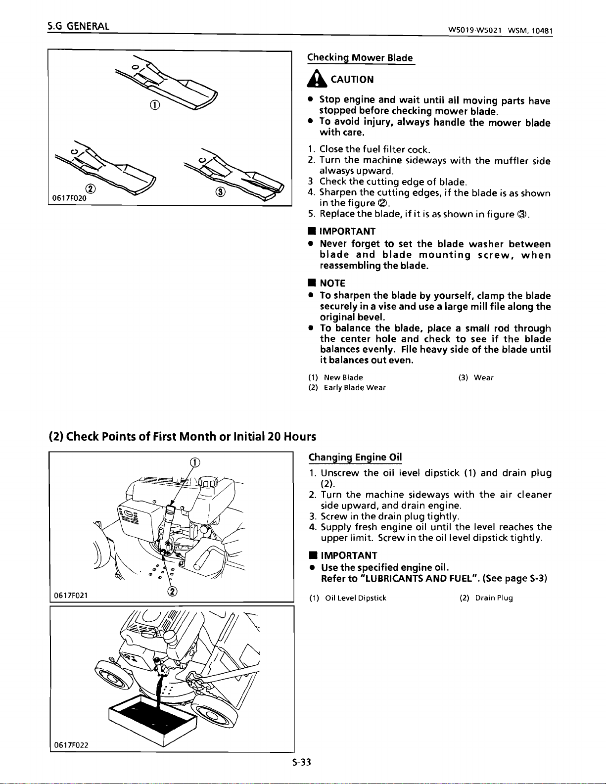
S.G
GENERAL
W5019W5021
WSM.104S1
Checking
Mower
Blade
A CAUTION
• Stop engine and
stopped before checking
•
To
avoid
with
1.
Close
2. Turn
alwasys upward.
3 Check
4. Sharpen
the
in
5. Replace
• IMPORTANT
• Never
blade
reassembling
NOTE
•
•
To
sharpen
securely in a vise and use a large
original bevel.
To
•
the
balances evenly. File heavy side
it
balances
(1)
New
(2) Early Slade
injury,
care.
the
fuel
the
machine sideways
the
cutting
the
figure~.
the
forget
and
balance
center
Slade (3)
Wear
wait
until
mower
always handle
filter
cock.
edge
of
cutting
blade,
blade
the
the
hole
out
edges,
if it
is
as
to
set
the
mounting
the
blade.
blade
by
yourself, clamp
blade, place a small rod
and check
even.
all
moving
the
with
blade.
if
the
shown in
blade
washer
to
blade.
mower
the
blade
figure
screw,
mill
file
see
if
of
the
Wear
parts have
blade
muffler
is
as
shown
<3>
.
between
when
the
blade
along
through
the
blade
blade
until
side
the
(2) Check Points
0617F021
of
First
Month
or
Initial
20
Hours
Changing Engine Oil
1.
Unscrew
(2).
2. Turn the machine sideways
side upward, and drain engine.
3.
Screw in
4. Supply fresh engine oil
upper
• IMPORTANT
Use
•
Refer
(1) Oil Level Dipstick
the
oil level dipstick (1) and drain
the
drain plug
limit.
Screw in the oil level dipstick
the
specified engine oil.
to
"LUBRICANTS AND FUEL".
with
tightly.
until
the
the
level reaches
(See
(2) Drain Plug
air
tightly
page
plug
cleaner
the
.
S-3)
0617F022
S-33
Page 65

WS019WS021 WSM,10481
S.G
GENERALITES I AllGEMEINES
Verification de
A,.ATIENTION
•
Arreter
to
utes les pieces mobiles
de
verifier
• Pour eviter d'etre blesse,
lame avec precaution.
1.
Fermer Ie robinet du
2. Tourner lateralement la machine
pot
d'echappement toujours dirige vers lei haul.
3. Verifier
4. AffGter
qu'elle est montree a la
5. Remplacer la lame
• IMPORTANT
•
Ne
jamais oublier d'installer la rondelle de la lame
entre la lame
remontage de la lame.
• NOTA
• Pour affGter soi-meme
sure
la
lime aparer
• Pour equilibrer
travers
s'equilibre de
de
la
reguliere.
(1)
lame
(2) Usure de la lame
nouvelle (3) Usure
la
lame
Ie
moteur
la
lame.
les
bords tranchants de la lame.
les
bords tranchants
et
lame dans un etau
Ie
I'orifice
lame jusqu'a
et
attendre
se
manipuler
filtre
acarburant.
figure~.
si
elle telle qu'a la figure
la vis de
long du
la
fa~on
primitive
fixation
la
cOte
lame, placer une petite
central
ce
et
uniforme. Limer Ie
qu'elle s'equilibre de
jusqu'a
soient arretees avant
avec
si
la lame est
de
la lame lors du
lame, serrer de
et
utiliser une grande
biseaute original.
verifier
(2) Points averifier premier mois ou
20
premieres
heures
ce
toujours
Ie
cOte
telle
@.
fa~on
tige
si la
lame
cOte
lourd
fa~on
que
la
du
Oberprufen des Messers
A,.VORSICHT
• Den
• Um eine Verletzung zu vermeiden, das Messer
1.
2.
3. Die Schneidkanten
4. Die Schneidkanten schaden, wenn
5.
•
• Beim
• ANMERKUNG
•
a
• Um das Messer auszuwuchten, einen kleinen Stab
(1) Neues Messer
(2) FrOhzeitige Messerabnutzung
(2) Nach 1
Motor
bewegenden Teile zum Stillstand gekommen sind,
bevor das Messer
stets vorsichtig handhaben.
Den
Kraftstoffilterhahn schlieBen.
Die Maschine
Schalldampferseite stets nach oben weist.
aus
der Abbildung ~ersichtlich aussieht.
Das
Messer auswechseln,
Abbildung @ ersichtlich aussieht .
WICHTIG
vergessen, die Messer-Unterlagscheibe zwischen
dem Messer und
anzubringen .
Urn
das Messer selbst
einen Schraubstock einspannen und
groBen Feile entlang der urspOnglichen Schneide
scharien.
in
das
Messer
Seite des Messers abfeilen, bis dieses gleichmtiBig
ausgewuchtet ist.
Stunden zu
abstellen und
uberpruft
auf
die Seite kippen,
des
Wiedereinbauen
der
Mittelloch
richtig
Monat
stecken und nachprOfen, ob das
ausgewuchtet
oder
uberprufende
warten,
wird.
Messers
wenn
des
Messer-Montageschraube
zu
scharien, dieses fest in
(3) Abnutzung
bis
so
C1berprClfen.
das
Messer
es
wie
Messers
ist. Die schwere
nach den ersten 20
Punkte
aile
daB die
aus der
niemals
mit
einer
sich
wie
"'"
•
Changement de I'huile
1.
Devisser la
bouchon de vidange (2).
2. Tourner lateralement la machine
filtre
a air dirige
moteur.
3.
Revisser
4. Faire I'appoint d'huile fraiche jusqu'a
arrive a
de niveau d'huile.
• IMPORTANT
• Utiliser I'huile moteur specifiee.
Se
reporter it "LUBRIFIANTS
(Voir page
(1) Jauge de niveau d'huile
jauge
Ie bouchon de vidange.
la
limite
S-4)
moteur
de niveau
vers
Ie haut
superieure. Bien revisser la jauge
d'huile
avec
et
vidanger
ET
CARBURANT".
(2) Bouchon
(1)
Ie
ce
de
cOte
et
Ie
du
I'huile
qu'elle
vidange
Wechseln des
1.
Den
abschrauben.
2.
Die
Luftfilterseite zur Seite kippen, und
ablassen.
Motorals
blmeBstab
Maschine
(1)
und die AblaBschraube
mit
nach
oben
wei
das
sender
Motorol
3. Die AblaBschraube fest hineinschrauben.
4. Frisches
Grenzmarke erreich. Dann den OlmeBstab wieder
fest hineinschrauben.
•
WICHTIG
•
Das
Siehe
KRAFTSTOFF".
(1) Olmel3stab
Motorol
vorgeschriebene
Abschnitt
einfCIllen, bis
(Siehe Seite
es
die
Motoral
"SCHMIERMITTEL
verwenden.
S-4)
(2) Ablal3schraube
(2)
obere
UND
S-34
Page 66

S.G
GENERAL
W5019W5021
WSM.l0482
(3) Check Points
(4) Check Points
~
SAllF002
of
Every 3
of
Every 6
Months
Months
.:
..
..
'
..
~
.
"
-.
or
50
Hours
or
100 Hours
Cleaning
Refer
(See
Changing Engine Oil
See
Cleaning and Readjusting Spark Plug
1.
electrode
2.
3.
specifications, repair
4.
5.
Spark plug
Tightening
Air
Cleaner Element
to
"Checking
page
5-31)
page
5-33.
Remove
Measure
If
If
cracked, replace
If
the
cap.
the
spark plug, and clean carbon
with a wire
the
spark plug gap
the
measurement does
the
electrode
spark plug cap
gap
torque
Air
Cleaner Element".
brush.
or
replace
or
insulator
the
spark plug.
is
defective, replace
Factory
spec.
Spark plug
with
not
meet
the
from
a feeler gauge.
the
factory
spark plug.
is
deformed
the
plug
0.7toO.8mm
0.028toO.031 in.
98
to
24.5 N·m
to
2.5
1.0
7.2to18.1
k~f.m
-Ibs
the
or
SA11F047
Except
B048F004
(1) Fuel Tank
(2) Fuel
(3) Fuel Tank
Cock
(-PCC,
and Filter
-SCC,
Q
&
-HTC)
(-PCC,
(4) Fuel
(5) Fuel Filter
(6)
(ock
(lamp
-SCC,
®
i
n
-HTC)
• IMPORTANT
• When replacing
resistor spark plug .
• When replacing
a resistor plug cap.
Cleaning Fuel Filter
(-PCC,
-SCC,
-HTC)
1.
Close
the
fuel cock (4) and remove
and fuel
2.
Clean
damage.
• IMPORTANT
• Place
toward
(Except
1. Empty the fuel
and
2.
Clean
damage.
the
the
the
-PCC,
filter
the
filter
(5).
fuel
If
damaged, replace it.
filter
tank.
-SCC,
(2)
from
fuel
If
damaged, replace it.
the
spark plug,
the
spark plug cap, be sure
filter
with
with
its
-HTC)
tank
(1) and remove
the
fuel tank.
filter
with
be
solvent and check
"MADE
solvent
sure
to
use a
to
the
clamp (6)
IN
USA"
the
fuel cock
and check
use
for
face
for
5-35
Page 67

W5019·W5021
WSM,10482
S.G
GENERALITES I ALLGEMEINES
(3) Points it
toutes les
Nettoyage de
Se
reporter a "Verification de I'element
air",
(4) Points it
toutes
Changement de I'huile
Voir page
Nettoyage
1.
Deposer la
I'electrode aI'aide d'une brosse metallique.
2.
Mesurer I'ecartement
verifier
50
I'eh~ment
(Voir page S-32)
verifier
toutes
heures
du
toutes
les 3 mois
filtre
aair
les 6 mois ou
les 100 heures
moteur
S-34.
et
reajustage de la bougie d'allumage
bougie
d'allumage,
des
electrodes de la bougie
ou
du
et
decalaminer
filtre
aI'aide d'une jauge d'epaisseur.
3.
Regier
,'ecartement
pas
4.5i
remplacer la bougie d'allumage.
5.
Si
defectueux,
Ecartement des
electrodes
bougie d'alfumage
Couple
• IMPORTANT
Si
•
neuve, veiller a utiliser une bougie d'allumage a
resistance.
•
Si
tension par un neuf, veiller
de cable de haute-tension
Nettoyage
(-pee, -sec, -HTe)
1.
Fermer Ie
(6)
2.
Nettoyer Ie
verifier s'i! est endommage.
endommage.
ou
remplacer
des
la
bougie
electrodes mesure ne correspond
ala valeur de reference.
I'electrode
Ie capuchon
de
de
serrage
on
remplace la
on remplace Ie capuchon
et
Ie
filtre
ou
de
Ie
remplacer.
la
du
filtre
acarburant
robinet
acarburant (5).
filtre
l'isolant
cable
Valeur de
reference
Bougie 9,8
d'allumage 1,0
bougie
de
iii
acarburant (4)
a carburant avec du solvant
d'allumage
est
deforme
haute-tension
0.7<'10,8
d'allumage
de
cable de haute-
ou
mm
a24,5 N'm
a2,5
kgt·m
par
it utiliser un capuchon
resistance.
et
retirer la bride
Le
remplacer s'il est
a
si
fele,
est
une
et
(3) Aile 3
Monate
oder
aile
50
Stunden zu
OberprOfende Punkte
Reinigen der Luftfiltereinsatze
Siehe
einsatze". (Siehe Seite 5-32)
(4) Aile 6
Abschnitt
Monate
"UberprOfen
oder
aile 100 Stunden zu
der
Luftfilter-
OberprOfende Punkte
Wechseln des
Siehe Seite
Reinigen und Nachstellen der ZOndkerze
1.
Die ZOndkerze
DrahtbOrste Olkohle von der Elektrode entfernen.
2.
Mit
einer
messen.
3.
Stimmt
Oberein,
ausbessern.
4.
1st
die
gesprungen, die Zondkerze austauschen.
5.
1st
der Kerzenstecker fehlerhaft, ihn austauschen.
Elektrodenabstand
Anzugsdrehmoment
• WleHTIG
• Beim Austauschen
daB eine ZOndkerze
eingesetzt
•
Beim
sichergehen.
gebautem Widerstand eingesetzt
Reinigen des
(-pee, -sec,
1.
Den
Klammer (6) und das
2.
Das
kraftstoffilter
auf
Beschadigung OberprOfen. Bei Beschadigung
ist das
Motorols
S-34.
ausschrauben
FOhlerlehre
der
MeBwert
die
ZOndkerze
Elektrode oder Kerzenstein
wird.
Austauschen
daB
Kraftstoffilters
-HTC)
Kraftstoffhahn
filter
zu ersetzen.
den
Elektrodenabstand
nicht
austauschen
Werkdaten
ZOndkerze
der
ZOndkerze sichergehen,
mit
eingebautem Widerstand
des
ein
Kerzenstecker
(4)
schlieBen,
Karaftstoffilter
mit
Losungsmittel reinigen und
und
mit
den
Werkdaten
verformt
0,7bisO,8mm
9,8
bis
24,5 N'm
bis
2,5
1,0
Kerzensteckers
wird.
mkp
mit
dann
(5) entfernen.
einer
oder
oder
I
ein-
die
• IMPORTANT
• Placer
reservoir.
(sauf -pee, -sec, -HTe)
1.
Vider
robinet de carburant
carburant.
2.
Nettoyer Ie
verifier s'it est endommage.
endommage.
(1) Reservoir
(2) Robinet
(3) Reservoir de carburant
Ie
filtre
Ie
reservoir
de
et
filtre
avec
filtre
carburant
acarburant
sa
de
et
a carburant avec du solvant
face "MADE IN USA" vers Ie
carburant
Ie
filtre
(1)
et
retirer
(2) du reservoir de
Le
rem placer s'il est
(4) Robinet de carburant
(5) Filtre
(6) Bride
<'I
carburant
Ie
et
• WleHTlG
•
Das
Filter
mit
der Aufschriftseite "MADE IN USA"
gegen den Tank weisend anbringen.
(auBer -pee, -sec, -HTe)
1.
Den
Kraftstofftank
Kraftstoffhahn
Kraftstofftank
2.
Das
kraftstoffilter
auf
Beschadigung OberprOfen.
das
ist
(1) Kraftstoffbeh31ter
(2)
(3) Kr aftstoffb@hlilt@r
S-36
filter
Kraftstoffhahn
und
abtrennen.
mit
zu ersetzen.
und kraftstoffilt@r
(1)
leeren,
kraftstoffi
Losungsmittel reinigen und
dann
Iter
(2)
Bei
Beschadigung
(4)
Kraftstoffhahn
(5)
Kraftstofffilter
(6) Klammer
den
vom
Page 68

S.G
GENERAL
0617F024
Adjusting Throttle Lever
1.
Set
the
throttle
2.
Adjust
the
and
3.
Check
position (Open)
"Hi" position and
when
4.
Start
"Stop" position
(1) Choke
(2) Speed Control Lever
(3)
(4)
(5) Lock
(6) Choke
the
speed control lever
then
that
the
the
Rod
..
Hi"
Position Stopper
Throttle
Cable Adjusting Screw
Nut
Arm
lever
throttle
tighten
the
throttle
engine, and
Retaining Screw
cable adjusting screw
the
choke arm
when
at
lever
to
assure
W5019W5021 WSM,10481
to
the
"Hi" position.
(4)
until
(2)
contacts
lock nuts
(6)
the
throttle
its right most position (Close)
is
at
the
set
the
that
the
stopper
(5).
is
at
its
left
lever
is
"Choke" position.
throttle
the
(a)
(b) "Close"
lever
engine stops.
"Open"
most
at
to
(3),
the
the
0617F025
0617F026
~
(a)
~
(b)
5-37
Page 69

W5019W5021 WSM.10481
S.G
GENERALITES I ALLGEMEINES
Reglage du levier d'accelerateur
1.
Regier Ie levier d'accelerateur
2.
Regier la
jusqu'a
entre
serrer
3.
verifier
la plus
vis
de rt!glage du cable d'accelerateur (4)
ce
que
Ie
levier de commande de vitesse
en
contact
les
contre-ecrous
que
avec
Ie dispositif
Ie
bras du starter
a gauche (ouverture)
d'accelerateur est ala position
la plus
a
droite
(fermeture)
sur"
(5).
(6)
lorsque
"Hi"
lorsque
d'accelerateur est a la position "Choke".
4.
Mettre
d'accelerateur
que
(1)
Vis
starter
(2)
Levier de commande de vitesse
(3)
Dispositif
(4)
Vis
d'accelerateur
(5)
Contre-ecrou
(6)
Bras
Ie moteur en marche
a la position "Stop" pour s'assurer
Ie
moteur s'arrete.
de fixation de
de reglage du cllble
du starter
la
tige
d'arr~t
de
et
(a) "Ouverture"
(b)
"Fermeture"
Hi".
d'arr~t
soit a
(3), puis
la
position
Ie
et
ala position
Ie
regler
Ie
(2)
levier
levier
levier
Einstellen
1.
Den
des
Drosselklappenhebels
Drosselklappenhebel
auf
die Position
einstellen.
2.
Die Drosselklappenseilzug-Einstellschraube (4)
verstellen, bis der Geschwindigkeitsregelhebel
mit
dem Anschlag
die Gegenmuttern
3.
NachprOfen,
Einstellung
des
(3)
in BerOhrung kommt, dann
(5)
anziehen.
ob
sich
der
Chokearm
Drosselklappenhebels
(6)
auf
ganz links (geoffnete Stellung) und bei Einstellung
auf "Choke" ganz rechts (geschlossene Stellung)
befindet.
4.
Den
Drosselklappenhebel
sich
Motor
zu
vergewissern, daB
anlassen,
auf
"Stop"
der
und
einstellen, um
Motor
abgestellt
wird.
"Offnen"
(1)
Chokestab-Haltesch raube
(2)
Geschwindigkeitsregelhebel
(3)
Anschlag auf
Drosselklappenseilzug-
(4)
Einstellschraube
Gegenmutter
(5)
Chokearm
(6)
"Hi"
(a)
"Schlie Ben"
(b)
"Hi"
(2)
bei
"Hi"
den
I
5-3B
Page 70

S.G
GENERAL
W5019W5021
WSM,10482
0617F027
Adjusting
1.
Make sure
blade
speci
2.
Measure
dutch
(-PC,
Before
control lever (2)
blade
3.
If
Mower
Blade Clutch Lever (Except -P, -T)
that
clutch
lever
fications.
the
free play
lever.
-pee,
-se,
-sec,
measurement,
dutch
lever.
the
distance (L2-L 1) is
the
to
specifications, loosen
the
4.
Retighten
5.
Start
lever
the
distance
the
to
lever
(L2-L
1)
with
the
lock nuts.
engine and move
check
to
assure
is
engaged and stops
released.
-PC,
·PCC,
-SCC,
travel
Total
Distance
Mower
(1)
(2) Blade Safety Control Lever
(lz)
(lz-l,)
Blade Clutch
-TC
-TCE,
-PC,
-sec,
-TC
-TCE,
·SCE
-HTC
-PCC,
·SCE
-HTC
lever
total
(1)
(l1)
-SeE)
push
the
left
the
the
that
-SC
-se
travel
(L2)
of
the
is
within
of
to
not
within
lock nuts
the
the
mower
the
blade
engage
(3)
the
the
and adjust
adjusting screw (4).
the
mower
the
Factory
spec.
Factory
spec.
Factory
spec.
Factory
spec.
lock
(3)
(4) Adjusting Screw
blade
blade starts
when
the
165to175mm
6.50
140to
5.51
148to
5.83
138to
5,43
Nut
mower
factory
blade
safety
mower
factory
dutch
when
lever
to
6.89 in.
155
mm
to6.10
152 mm
to
5.98 in.
142 mm
to
5.59 in.
is
in.
0617F028
Adjusting
Drive Clutch Lever (Except
A CAUTION
•
Be
sure
that
front
of
the
mower
or
obstructions before operating.
1.
Make sure
dutch
2. Measure
3.
If
the
specifications, loosen
the
distance
4.
Retighten
5.
Start
clutch engages and disengages properly.
Total
travel
Distance (L2-l,)
(1) Drive Clutch
(2) Adjusting Screw
that
the
lever (1)
is
within
the
free play (l1)
distance (L2-L
(L2-L1)
the
lock nuts.
the
engine and check
(ll)
lever
total
1)
is
the
with
Factory
spec.
Factory
spec.
travel
(L2)
the
factory specifications.
of
the
drive
not
withi n the
lock nuts (3) and adjust
the
adjusting screw (2).
to
assure
90to97mm
3.54
86to95
3.39
(3)
lock
-P,
-PC,
is free
of
dutch
that
to
3.82 in.
mm
to
3.74 in.
Nut
-pee)
of
people
the
lever.
factory
the
drive
drive
S-39
Page 71

WS019WS021
WSM,10482
S.G
GENERALITES I ALLGEMEINES
Reglage
(Sauf
1.
du
levier d'embrayage de la lame
-P,·
T)
S'assurer
que
d'embrayage
la course
de
la
lame
totale
(1)
soit
(L2)
en
du
levier
dec;iI des
valeurs de reference.
2. Mesurer Ie jeu
libre
(11)
du
levier d'embrayage de
lalame.
(·pe, -pee, -se, -sec,
-SeE)
Avant la mesure, pousser Ie levier de commande
de
securite
engager
Ie
de
lame
levier
(2)
vers
la
d'embrayage
gauche
de
lame
tondeuse.
3.
Si
la distance
de reference, desserrer les
regler la distance
4.
Resserrer
5.
Mettre
d'embrayage de la lame
demarre lorsque Ie levier est engage
10rsqIJe
totale
Course
(L2)
Disatance
(L2-11)
(L2-11)
les
contre-ecrous.
en marche Ie
(L2-L
n'est
1)
avec la
moteur
pour
Ie levier est rel3che.
-Pc.
-PCC,
-SCC,
-TC
-PC,
-SCC,
-TC
-TCE,
-sc Valeur de
-SCE
,
TC
-PCC,
-SC
-SCE
-HTC
reference
Valeurde
reference
Valeurde
reference
Valeur de
reference
pas
en
deC;iI
des valeurs
contr~-ecrous
vis
de reglage (4).
et
deplacer Ie levier
verifier
que
la lame
et
s'arrete
165~
175mm
140~
155 mm
148 ~ 152 mm
138~142mm
pour
(3)
de
et
des
Einstellen
1.
Sicherstellen,
Messerkuppl
Messerkupplungshebels (AuBer -P,
daB
der
ungshebels
Gesamthub
(1) i nnerhal b der
(L2)
Werkdaten lieght.
2.
Das
freie
Spiel
(L1)
des Messerkupplungshebels
messen.
(-Pc, -pee. -se,
-sec,
-SeE)
Vor der Messung den Sicherheitsreglerhebel (2)
des
Messers
Messerkupplungshebel eigreifen
3.
Wenn
die
nach
Entfernung
Ii
nks
(L2-L1)
drucken,
zu
lassen.
nicht
innerhalb
urn
Werkdaten liegt, die Gegenmuttern (3) losen, und
die
Entfernung
(L2-
L 1)
mit
Hi Ife d er
Einstellschraube (4) einstellen.
4.
Die Gegenmuttern
5.
Den
Motor
Messerkupplungshebel
sicherzustellen, daB sich das Messer
beginnt.
wenn
wieder
anziehen.
anlassen,
der
Hebel eingezogen
und
bewegen,
zu
wird,
drehen
daB das Messer beim loslassen des Hebels zum
Stillstand kommt.
-PC,
-Pce.
-sc
Gesamthub
(12)
Entfernung
(L2-11)
-SCC,
-TC
-TCE,
-PC,
-SCC,
-TC
-TCE,
-SCE
-HTC
-PCC,
-SCE
-HTC
Werkdaten 165 bis 175 mm
Werkdaten
-SC
Werkdaten
Werkdaten
140 bis 155 mm
148 bis 152 m m
138
bis
142
-T)
des
den
der
den
urn
und
mm
(1)
levier
d'embrayage de la lame (3) Contre-ecrou
levier
(2)
Reglage
{Sauf
de commande de (4)
securite de la lame
du
.p,
·pe, ·pee}
levier d'embrayage
Vis
de reglage
d'entrainement
A ATTENTION
• S'assurer que personne ni aucun obstacle ne
trouvent
marche.
1.
S'assurer
d'embrayage
valeurs de reference.
2. Mesurer
d'entrainement.
3.
Si
la distance
de reference, desserrer les contre-ecrous (3)
regler la distance
4.
Resserrer
5.
Mettre
I'embrayage
degage correctement.
Course
Dista nce
(1)
levier
d'entrainement
(2)
Vis
devant
que
Ie
les
en
totale
(L2)
(12-L
1)
d'embrayage
de reglage
1a
tondeuse
la
course
d'entrainement
jeu libre
(l2-l1)
(L2-L
(L1)
n'est
1)
avec
contre-ecrous.
marche
Ie
d'entrainement
Valeur de
reference
Valeur de
reference
avant
de la
totale
(l2)
(1) soit en
du
levier
pas
en
dec;iI
la
vis
de reglage (2).
moteur
et
s'enclenche
90~97mm
86~
95
(3) Contre-ecrou
mettre
du
levier
dec;a
d'embrayage
des
valeurs
verifier
et
mm
se
en
des
et
que
se
(1) Messerkupplungshebel
(2) Messer-Sicherheitshebe
(3)
Gegenmutter
(4) Einstellschraube
Einstellen des Antriebskupplungshebels
-P,
-Pc,
(AuBer
opeC)
A VORSleHT
• Vor der
Inbetriebnahme
keine Personen oder Hindernisse
befinden.
1.
Sicherstellen,
daB
Antriebskupplungshebels
Werkdaten liegt.
2.
Das
freie Spiel
(11)
messen.
3.
Wenn
Werkdaten liegt,
die
die
Entfernung
Entfernung
die
Einstellschraube (2) einstellen.
4.
Die Gegenmuttern
5.
Den
Motor
anlassen, dann sicherstellen, daB
wieder
Antriebskuppl u ng
ausgeruckt
Gesamthub
ntfernung
E
(1) Antriebskupplungshebel
(2) Einstellschraube
(L2)
(L2-L
wird.
1)
Werkdaten
Werkdaten
sicherstellen, daB sich
vor
der
Gesamthub
(1)
innerhalb
des
Antriebskupplungshebels
(L2-11)
nicht innerhalb
Gegenmuttern (3) losen, und
(L2-Ll)
mit
anziehen.
ei
nwa
nd
freiei
90bis97
86bis95
(3)
Gegenmutter
dem Maher
(L2) des
der
der
Hilfe
der
die
n-u nd
mm
mm
5-40
Page 72

S.G
GENERAL
W5019W5021
WSM.10482
(5) Check Points
(Except
-PCC,
-SCC,
B048F004
(Except
-PCC, -SCC,
of
Every Year
-HTCI
-HTC]
(-PCC,
(-PCC.
or
300 Hours
-SCC.
-HTC]
-SCC.
-HTC]
Cleaning Fuel Tank
1.
Empty
2.
(2), (5)
3.
Clean
Loosen
the
fuel
tank
(1), (4).
the
clamp (3). (6), and remove
from
the
fuel
tank
(1), (4).
the
inside
of
the
fuel
gasoline.
(1) Fuel Tank
(2) Fuel Cock
(3) Clamp
(4) Fuel Tank
(5) Fuel
(6) Clamp
CocK
and
Fileter
Replacing Fuel Pipe
1.
Replace
the
fuel pipe (1), (3)
pipe clamps (2), (4), (5) every year
whenever
(1) Fuel Pipe
(2) Pipe Clamp
(3) Fuel Pipe
(/I) Pipe Clamp
(5) Pipe Clam p
they
are
found
to
tank
together
be
damaged.
the
(1), (4)
or
300 hours,
fuel
with
cock
with
the
or
B04SF005
Checking Valve Clearance
See page
Checking
SeepageS-lOS, 107,
S-51.
Mower
Blade Clutch (Except
1(19.
-P, -T)
S-41
Page 73

WS019WS021 WSM,10481
S.G
GENERALITES I ALLGEMEINES
(5) Points averifier
les 300
Nettoyage
1.
Vidanger Ie carburant
heures
du
reservoir acarburant
tous
se
les
ans
trouvant
ou
toutes
dans Ie reservoir
acarburant (1), (4).
2.
Desserrer la bride (3), (6)
carburant
3.
Nettoyer Ie reservoir a carburant (1), (4) avec de
(2), (5)
du
I'essence.
(1) Reservoir a
(2) Robinet
(3) Bride
(tI)
Resersvoir aC1Hburant
(5) Robinet
(6) Bride
Remplacement
carburant
et
frlter acarburant
de
carburant
du
tuyau
carburant
1.
Remplacer Ie tuyau
(1), (3) en
d'alimentation
m~me
temps qu'avec
(2), (4), (5) tous
300 heures, ou chaque fois
sont endommages.
(1) Tuyau
(2) Bride
(3) Tuyau
(tI) Bride
(5) Bride
d'alimentation
du
tuyau
d'alimentation
du
du
d'alimentation
tuyau
d'alimentation
tuyau
d'alimentation
de
de
et
deposer Ie
robinet
reservoir acarburant (1), (4).
d'alimentation
d'alimentation
les
qu'on
carburant
carburant
de
de
carburant
les
brides
ans
du
ou toutes
decouvre qu'ils
de
tuyau
les
(5) Jahrlich
OberprOfende
Reinigen des
1.
Den
oder
aile 300
Kraftstoffbehalters
Kraftstoff
im
Stunden
Punkte
Kraftstoffbehalter
zu
(1),
ablassen.
2.
Die Klammer (3), (6) lasen, und den
(2), (5) vom
3. Die Innenseite des Kraftstoffbehalters (1), (4)
Kraftstoffbehalter
Kraftstoffhahn
(1), (4) entfernen.
Benzin reinigen.
(1)
Kraftstoffbehalter
(2)
Kraftstoffhahn
(3)
Klammer
(tI)
Kraftstoffbehalter
(5)
Kraftstoffhahn
(6)
Klammer
Auswechseln
1.
Die
Kraftstoffrahre
Klammern (2), (4),
und
Kraftstoffilter
der
Kraftstoffrohre
(5)
(1), (3) zusammen
mit
nach jeweils einem Jahr oder
300 Betriebsstunden hzw. bei Beschadigung dieser
leile
auswechseln,
(1
)
Kraftstoffrohre
(2)
Klammer
Kraftstoffrohre
(3)
(1I)
Klammer
Klammer
(5)
(4)
mit
den
Verification
Voir
du
jeu
page 5·52,
des soupapes
Verification d'embrayage de la lame (sauf
Voir page 5-106, 108,
110.
-Po
-T)
OberprGfen des Ventilspiels
5iehe 5eite 5-52.
der
OberprGfen
5iehe 5eite 5-106, 108,
Messerkupplung (AuBer
110.
•
-P, -T)
5-42
Page 74

S.G
GENERAL
W5019W5021
WSM,10481
[10]
STllF004
SPECIAL
TOOLS
Piston Ring Compressor
Code No : 07909-32111
Piston Ring Tool
Code No : 07909-32121
ST11F005
ST1lFOI2
=
Valve Seat Cutter
Code No 07909-33102
Angle
Diameter:
0.785 rad. (45°)
0.262 rad. (15")
28.6
mm
(1.126 in.)
31.6mm(1.244in.)
35.0
mm
(1.378 in.)
mm
38.0
41.3
50.8
(1.496 in.)
mm
(1.626 in.)
mm
(2.000 in.)
S-43
Page 75

WS019WS021
WSM,10481
S.G
GENERAUTES I ALLGEMEINES
[10] QUTILS SPECIAUX
Collier asegments
Reference: 07909-32111
Pince asegments
Reference: 07909-32121
[10] SPEZIALWERKZEUGE
Kolbenringverdichter
CodeNr
Kolbenringswerkzeug
Code Nr : 07909-32121
: 07909-32111
Rectifieuse pour
Reference: 07909-33102
Angle 0,785
Diametre:
Ie
siege de soupape
rad. (45°)
0,262 rad. (15°)
28,6
mm
31,6mm
35,Omm
38,Omm
41,3
mm
50,8mm
Ventilsitzschneider
Code Nr 07909-33102
Benutzung : 0,785
Durchmesser: 28,6
Rad.
0,262
Rad.
mm
31,6
mm
35,Omm
38,Omm
41,3
mm
50,8mm
(45")
(15°)
•
$-44
Page 76

S.G
GENERAL
•
NOTE
•
The
ST1IF301
following
E
VfJ
~
III
is
1.0
~
special
-,
1\1
0
""
~
9-
tool
is
120
(472)
50 (1.97)
'O"C7'O'
~2
III
is
....,
<:t
o-i
0
....
Q
<:to
O'l
not
provided; refer
1\1
C;
Q
N
t'-.
0
'"
0
....
~
Q
t'-.
9-
'"
15
(0.59)
~,
'\3
-,
III
C;
1.0
N
III
C;
N
0
0
<:t
0
...
1.0
'"
0
0
....
~
N
'"
""
8
'"
Unit:
to
~
mm
(in)
the
figure
for
specifications.
Valve Guide Replacing Tool
Application:
Use
valve guide.
Chamfer
C1
C2
C3
to
pullout
mm
2.0
1.0
0.3
WS019WS021 WSM,10481
and
to
press-fit
Unit:
mm
the
(in.)
in.
0.079
0.039
0.012
$-45
Page 77

W5019W5021 WSM,101181
S.G
GENERALITES!
ALLGEMEINES
• NOTA
•
l'outil
la
Outil
Utilisation: 5ert a
special
figure pour
de rem placement de
(hampfrein
suivant
les
soupapes.
(1
C2
C3
n'est
pas
specifications.
guide
retirer
et
installer les guides de
fourni;
de soupape
mm
se
Unite:
2,0
1,0
0,3
referer a
mm
• ANMERKUNG
• Oas
VentilfOhrungs-Ausbauwerkzeug
Benetzung: Zum
folgende
mitgeliefert;
entnehmen.
Abfassung mm
Spezialwerkzeug
Einzelheiten sind
Abziehen
Ventilfuhrung.
und
(1
C2
C3
wird
der
Abbildung
Prel3passung
Einheit:
2,0
1,0
0,3
nicht
zu
der
mm
5-46
Page 78

S.l
ENGINE
W5019W5021 WSM.10482
o
ENGINE
[1] SEPARATING ENGINE
DISASSEMBLING
AND
ASSEMBLING
Draining
1.
and
2.
Close
3.
Turn
side
(When
Tightening
torque
Engine
oil
Place an oil pan, and unscrew
drain
plug.
the
fuel
filter
cock.
the
machine sideways
upward,
and
drain
reassembling)
Drain
plug
• IMPORTANT
• Use
the
Refer
specified
to
"LUBRICANTS AND FUEL".
engine
(See page S-3)
Battery
1.
2.
3.
and
Wiring
Remove
battery
the
(5).
Disconnect
ignition
coil.
Disconnect
Harness (-SCE,·
battery
the
the
cover (7)
wiring
wiring
charging coil.
4.
Disconnect
the
wiring
starter.
5.
Remove
the
wiring
harness and
as a unit.
the
with
engine
oil.
connector
connector
connector
oil level dipstick
the
air
oil.
19.6
to
29 4 N·m
to
3.0 kgf-m
2.0
to
21.7 ft-Ibs
14.5
TCE)
and
dismount
(1)
from
(4)
from
(2)
from
battey
support
cleaner
the
the
the
the
(3)
(1)
Wiring
(2)
Wiring
Battery
(3)
(4)
Wiring
Throttle
1.
Unscrew
remove
2.
Remove
3.
Loosen
throttle
(1)
Mower
(2)
Throttle
Connector
Connector
Support
Connector
Cable and
the
the
the
the
Mower
joint
joint
cover (3).
mower
retaining
cable (2).
Blade Clutch Cable
Cable
(5)
Battery
(6) Cushion
Battery
(7)
Blade Clutch Cable
cover
blade
mounting
clutch cable (1).
screw,
(3)
and
Joint
Cover
Cover
screw,
remove
and
the
5-47
Page 79

WS019WS021
WSM,10482
5.1
MOTEUR I MOTOR
o
MOTEUR
[1] SEPARATION DU MOTEUR
DEMONTAGE
Vidange de
1.
Installer
niveau
2.
Fermer Ie
3. Tourner
filtre
moteur.
(Au remontage)
Couple
serrage
• IMPORTANT
•
Utiliser
Se
(Voir
Batterie
1.
Deposer Ie couvercle de
batterie
Deconnecter Ie connecteur
2.
bobine d'allumage.
3.
Deconnecter Ie connecteur de cablage
bobine
4.
Deconnecter
demarreur.
5. Deposer Ie faisceau de fils
(3) ensemble.
(1)
Connecteur de
Connecteur
(2)
Support
(3)
Connecteur
(4)
I'huile
un
d'huile
robinet
lateralement
a air
de
I'huile
reporter
page
S-4)
et
faisceau de fils
(5).
de charge.
de
de
batterie
de
ET
REMONTAGE
moteur
bac
et
dirige
Bouchon
moteur
d'huile
Ie
du
vers Ie
et
bouchon de vidange.
filtre
la machine avec Ie cote du
de
vidange
specifiee.
a "lUBRIFIANTS
(-SCE, -TCE)
batterie
Ie
connecteur
dlblage
dlblage
cablage
devisser la
acarburant.
haut
et
vidanger
19,6 a29.4 N'm
2,0
a3,0
ET
CARBURANT".
(7)
et
de
d3blage
de
cablage
et
Ie support de
(5)
Batterie
(6)
Plaque
(7)
Couvercle de
demonter
jauge
I'huile
kgf·m
(1)
(4)
(2)
batterie
batterie
de
la
de la
de la
du
o
[1] TRENNEN
AUSBAU
Ablassen des
1.
2. Den
3.
(Beim
Anzugs- bl B h b
drehmoment
• WICHTIG
•
Batterie und Kabelbaum
1.
2. Den Kabelstecker (1) von
3.
4. Den Kabelstecker (2) von Anlasser abziehen.
5.
(1) Kabelstecker (5)
(2) Kabelstecker
(3)
(4) Kabelstecker
MOTOR
DES
UND
Motorals
Eine
Olwanne
OlmeBstab und
Kraftstoffilterhahn
Die
Maschine
luftfilterseite
ablassen.
Wiedereinbau)
Das
vorgeschriebene
Siehe
KRAFTSTOFF". (Siehe Seite
Den Bateriedeckel (7) abnehmen und die Batterie
(5) ausbauen.
Den Kabelstecker (4) von
Den Kabelbaum und den
Einheit entfernen.
Batteriehalter
unter
die
zur 5eite kippen, und das
A a
Abschnitt
MOTORS
EINBAU
den
Motor
AblaBschraube abschrauben.
schlieBen.
mit
nach
sc
rau e
Motoral
"SCHMIERMITTEl
(-SCE,
der
der
Batteriehalter
(6) Platte
(7)
stellen,
oben
19,6 bis 29.4
2,0 bis 3,0
verwenden
S-4)
-TCE)
ZOndspule abziehen.
ladespule
Batterie
Batteriedeckel
dann
weisender
Motorol
mkp
.
abziehen.
(3) als eine
den
Nm
UND
•
Cable d'accelerateur
de la lame
1.
Devisser la vis
deposer Ie cache-joint (3).
2.
Debrancher Ie cable d'embrayage de la lame (1).
3.
Desserrer
d'accelerateur (2).
(1) Cable
(2) Cable
d'embrayage
lame
d'accelerateur
la
et
de
vis,
de la
cable
d'embrayage
fixation
et
debrancher
(3) Cache·joint
du
cache-joint,
Ie
et
cable
Drosselklappenseilzug und Messerkupplungsseilzug
1.
Die
Gelenkabdeckungs-Montageschraube
und
die
Gelenkabdeckung (3) entfernen.
2.
Den Messerkupplungsseilzug (1)
3.
Die
Drosselklappenseilzug (2)
(1) Messerkupplungsseilzug
(2) Drosselkiappenseilzug
5-48
Halteschraube
entfernen.
(3)
entfernen.
losen,
Gelenkabdeckung
und
losen,
den
Page 80

S.1
ENGINE
Joint
1.
Remove
2.
Pull
the
(Except
the
out
the
sub
PTO
.p,
-PC,
-pee)
external snap
pin
(2), and remove
shaft.
WS019WS021 WSM.10482
ring
(1).
the
joint
(3)
from
0617F019
(When
• The pins (2). (4)
(1) External Snap
(2)
(3)
reassembling)
same plane.
Pin
Joint
(See
RlI1g
of
the
figure)
joint
must
always be in
(4)
Pin
(5) External Snap Ring
the
Blade and Turbofan
1.
Turn
the
machine sideways
with
the
muffler
side
upward
2.
Wedge
blade and
will
3.
Unscrew
remove
4.
Unscrew
remove
(When
Tightening
torque
(1) Block
(2) Blade
5
(3)
a block
safely
hold
the
the
the
the
reassembling)
of
Wood
Mounting
Turbofan
Mounting
of
the
housing
the
blade
blade (4).
turbofan
turbofan
Blade
screw
Screw
Screw
wood
in
blade.
mounting
mounting
(5).
mounting
(1) securely
such a
position
screws
screws (3), and
4g.0
5.0
36.2
(4) Blade
Turbofan
(5)
(6) Blade
Washer
between
(2),
to
588
to
6.0
kgf·m
to
43.4 ft-Ibs
that
N'm
one
it
and
0617F031
Separating Engine
1.
Unscrew
the
engine.
S-49
the
engine
mounting
nuts, and separate
Page 81

WSO'9WS021
Joint
(Sauf
L Deposer Ie
2.
Enlever la
WSM,
-P,
-PC,
cirdip
goupille
'0482
-pee)
externe (1).
(2)
et
deposer Ie
I'arbre auxiliaire de prise de force.
joint
(3) de
-P,
·pe,
Gelenk (AuBer
pee)
1 Den auBerer Sicherungsring
2.
Den
Stift
(2) herausziehen, und das Gelenk (3) von
der
Hilfszapfwelle entfernen.
5.1
MOTEURI
(1)
entfernen.
MOTOR
(Au remontage)
Les
•
(1) Circlip
goupilles (2)
etre sur
(2)
Goupille
(3)
Joint
Lame
1.
Tourner lateralement la machine avec Ie cote
Ie
meme plan. (Voir la figure)
externe
et
turbo-ventilateur
pot d'echappement
2.
Caler de
lame
et
fac;on
Ie
et
sure
carter de
(4)
du
joint
(II)
Goupille
(5)
(irclip
dirige
vers
un
bloc de bois (1)
fac;on
qu'il
doivent
exteme
Ie haut.
maintienne
risque la lame.
3.
Devisser
les
vis
de
fixation
de la lame (2)
et
la lame (4).
4.
Devisser
et
les
deposer Ie
vis
de
fixation
du turbo-ventilateur (3)
turbo-ventilateur
(5).
(Au remontage)
Vis
de
Couple
serrage
(1) Bloc
(2)
Vis
(3) Vis
ventilateur
de
de
de
de
bois
fixation
fixation
lame
de
du
la
lame
turbo·
fixation
de
la 49,0 a58,8 N·m
5,0 a6,0
(4) Lame
(5)
Turbo·ventilateur
(6) Rondelle
de
la
toujours
entre
sans
deposer
kgf·m
lame
(Beim Wiedereinbau)
• Die Stifte (2), (4)
der gleichen Ebene befinden. (Siehe
(1)
AuBerer
(2)
Stift
(3)
Gelenk
Messer und Turbogeblase
du
1.
Die Maschine
Schalldampferseite nach oben weist.
2.
Ein
la
Holzstuck (1) fest zwischen das Messer
Gehause
festgehalten
3.
Die IVlesser-Montageschrauben (2) Ibsen, und
Messer (4) entfernen.
4.
Die Turbogeblase-Montageschrauben (3) Ibsen,
und
(Beim Wiedereinbau)
Anzugs- Messer- 49,0 bis 58,8
drehmoment
(1) HolzstOck (4) Messer
(2) ME>sSE>r·Montageschraube
(3)
Turbogeblase-
Montaqeschraube
Sicherungsring
drucken,
wird.
das
Turbogeblase
des
Gelenks mussen
auf
die
Seite
so daB das
(5)
entfernen.
Montageschraube
(5)
(6) Messer-Unterlagscheibe
(4)
Stift
(5)
AuBerer
kippen,
5,0
Turbogeblase
sich
stets
Abbildung)
Sicherung5ring
so
daB
Messer
6,0
N'm
mkp
bis
auf
die
und
sicher
das
Separation
1.
Devisser les ecrous
separer
du
moteur
Ie
moteur.
de
fixation
du
moteur,
et
S-50
Trennen des
1.
Die
Motor-Montagemuttern
trennen.
Motors
Ibsen, und den
Motor
Page 82

S.l
ENGINE
[2] ENGIN E BODY
W50
19W502
1 WSM, 10481
CHECKING
AND
ADJUSTING
Valve Clearance
• IMPORTANT
• Valve clearance
when
engine is cold.
1.
Remove
2.
Remove
3.
Remove
4.
Put
NOTE
•
• Turn
be closed
immediately
the
the
the
air
the
bonnet
the
cylinder head cover.
piston
in
rotor
clockwise. and
first
opened
decompression pin.
been
compression
5.
Check
closed
the
intake
again.
top
a feeler gauge.
6.
If
the
clearance
specifications, adjust
•
NOTE
•
After
adjusting
adjusting
nut
with
must
be checked and
cleaner cover.
with
the
recoil starter.
the
compression
and
the
for a short
After
the
exhaust
top
dead center.
the
intake
valve
time
the
exhaust valve has
piston
comes
dead center.
and exhaust valve clearance
is
not
the
with
valve
the
within
the
adjusting nut.
clearance. secure
lock
nut.
the
adjusted
valve
will
will
by
the
in
the
with
factory
the
be
DISASSEMBLING AND ASSEMBLING
(1) External Components
Intake
and
valve clearance (Cold)
Tightening
Mower
1.
Remove
2.
Remove
exhaust
torque
Blade Clutch
the
recoil starter (5).
the
return
three flange screws (3).
3.
Fix
the
rotor
with
flange screw (2).
4.
Tap
the
flange screw
remove
the
mower
(When reassembling)
•
Apply
Bond
molybdenum
1901
or
equivalent)
crankshaft.
(1)
Mower
Blade Clutch
(2)
Flange Screw
(3)
Flange Screw
Factory
spec
Lock
nut
spring
0.05toO.l0mm
00020
7.8to12.7N·m
0.8
5.8
(4) and
to
0.0039 in.
to
1.3
kgfm
to
9.4 ft·lbs
unscrew
a brass rod, and loosen
with
a plastic
hammer
blade clutch (1).
disulfide
to
the
(4)
Return Spring
(5)
Recoil
lubricants
spline
Starter
the
the
to
(Three
of
the
I
S-51
Page 83

WS019WS021
[2]
CORPS
WSM,10481
OU
MOTEU R
[2] MOTORKORPER
5.1
MOTEUR/MOTOR
VERIFICATION
Jeu
des soupapes
• IMPORTANT
•
le
jeu
des soupapes
suivant
1.
Deposer Ie couvercle de
2.
Deposer Ie capot avec Ie lanceur de demarrage.
3.
Deposer Ie couvercle de culasse.
4.
Amener Ie piston au
de compression.
• NOTA
• Tourner Ie
montre
premier
immediatement
moment
la
fermee, Ie piston
la
5.
Verifier
d'echappement it I'aide
6.
Si
de reference, regler it I'aide de I'ecrou de reglage.
• NOTA
• Apres
de
leu
(a
Couple de serrage
les besoins avec Ie
rotor
et
la soupape d'admission sera fermee en
et
par la
soupape
course
Ie
reglage avec Ie contre-ecrou.
des soupapes
froid)
de compression.
Ie
jeu
n'est pas compris dans la gamme de valeur
avoir
ET
REGLAGE
doit
etre
verifie
moteur
filtre
point
mort
dans Ie sens des aiguilles
la
soupape
ouverte
goupille
d'echappement a de
se
jeu
de
regie Ie jeu de soupape, serrer I'ecrou
Valeur de
reference
Contreecrou
d'echappement
de
decompression. Apres
trouve
soupape
d'une
it air.
haut
pendant
au
point
d'admission
jauge
0,05
7,aa12.7N·m
o,a
froid.
et
de la course
un
nouveau
mort
d'epaisseur.
a0,10
mm
a
1,3
kgf·m
regie
d'une
sera
court
haut
ete
de
et
OBERPRUFUNG UNO EINSTELLUNG
Ventilspiel
• WICHTIG
Das
•
1.
2.
3.
4.
• ANMERKUNG
• Den Rotor gegen den Uhrzeigersinn drehen.
5.
6.
• ANMERKUNG
•
Ventilspiel muB bei
und
eingestellt
Den
Luftfilterdeckel
Die
Motorhaube
entfernen.
Die Zylinderkopfhaube entfernen.
Den
Kolben
Verdichtungshub bewegen .
EinlaB
AuslaBventii
Dekompressionsstift
Nachdem sich das AuslaBventil
bewegt
im
Das EinlaBFOhleriehre OberprOfen.
1st
Hilfe
Einstellung vornehmen .
Nach
Einstellmutter
EinlaBAuslaBventilspiel
(Kalt)
Anzugsdrehmoment
vesntil
sieh der Kolben
Verdichtungshub.
das Spiel
der
dem
und
werden.
zum
sehlieBt
affnet
und
nicht
Einstellmutter
Einstellen
mit
der
Gegenmutter
kaltem
entfernen.
mit
dem
oberen
sich
unmittelbar
in
Aus/aBventilspiel
innerhalb der
des
Gegenmutter
Werkdaten
Motor
RuckstoBanlasser
Totpunkt
zuerst,
sieh
fUr
wieder
den oberen
Werkdaten,
eine
entsprechende
Ventilspiels
0,05
7.B
O,B
Gberpruft
und
durch
kurze
sehlieBt,
Totpunkt
mit
sichern.
bisO.l0
mm
bis 12.7 N'm
bls
1.3
mkp
einer
im
Das
das
den
Zeit.
mit
die
•
OEMONTAGE
ET
REMONTAGE
(1) Composantes externes
Embrayage de la lame
1.
Deposer Ie lanceur de demarrage (5).
2.
Deposer Ie ressort
vis it
bride
(3).
3.
Fixer Ie
bronze
4.
Frapper
marteau en plastique
de la lame (1).
(Au remontage)
Appliquer
•
(Three
cannelure
(1) Embrayage de la lame
Vis
(2)
(3)
Vis
et
Bond
abride
abride
volant
desserrer la
doucement
un
du
de
rappel (4)
magnetique
vis
sur la vis it
pour
lubrifiant
1901
vilebrequin.
it bisulfure
ou
it bride (2).
deposer
son
(1\)
Ressort de rappel
(5) Lanceur de
et
devisser
avec
une
bride
I'embrayage
de
molybdene
equivalent)
demarrage
les
tige
avec
trois
en
un
it
la
AUSBAU UNO EINBAU
(1) AuBere Bauteile
Messerkupplung
1.
Den ROckstoBanlasser (5) entfernen.
2.
Die ROckholfeder (4)
Flanschschrauben (3)
3.
Den Rotor
die Flanschschraube (2) losen.
4.
Mit
Flanschschraube klopfen, um
(1)
entfernen
(Beim Wiedereinbau)
•
Molybdandisulfid-Schmiermittel
1901
Kurbelwelle
(1)
Messerkupplung
(2}
Flal1Schschraube
(3)
Flanschschraube
S-52
mit
einem
oder
gleichwertige)
Kunststoffhammer
zu
auftragen.
IOsen.
einem Messingstab arretieren, und
kOnnen.
entfernen,
die
auf
die
Ruckholfeder
(1\)
(5)
Riickstof3anlasser
und
die
drei
leicht
Messerkupplung
auf
(Three
Uingsnut
die
Bond
der
Page 84

S.1
ENGINE
WS019W5021 WSM,10481
0617P005
Bonnet,
1.
Air
Unscrew
Cleaner and
the
two
cleaner cover (1) and
2.
Unscrew
remove
3.
Unscrew
nuts, and
the
the
the
remove
bonnet
air
gasket.
4.
Unscrew
and remove
(1)
Air
(2)
Element
(3)
Air
Fuel
Tank
1.
Disconnect
the
the
Cleaner Cover (4)
Cleaner
Case
the
(3).
2.
Unscrew
remove
(1) Fuel Tank
(2) Fuel Tank Stay
the
the
fuel
fuel
wing
bonnet
(4) .
cleaner
muffler
muffler
fuel
tank
tank
Muffler
screws, and
element
mounting
case
the
air
cleaner
mounting
(5) and gasket.
(S)
pipe
(4)
stay
mounting
(1)
with
(3)
(4)
remove
(2).
screws,
mounting
case (3)
nuts
Bonnet
Muffler
from
the
the
fuel
Carburetor
Fuel Pipe
the
and
screw and
and
and
screw,
carburetor
screws, and
tank
stay (2).
air
$-53
Page 85

W5019W5021
WSM,10481
5.1
MOTEUR I MOTOR
Capot,
1.
2.
filtre aair
Devisser les
couvercle du
Devisser
les
et
deux
filtre aair
vis
de
capot (4).
3. Devisser la
filtre a air
vis
et
et
deposer
lejoint.
4. Devisser la vis
d'echappement
(5)
et
Ie
joint.
Couvercle du
(1)
Element
(2)
Carter
du
(3)
filtre
filtre
i\ air
et
et
i\ air
Reservoir acarburant
1.
Debrancher
(4) du carburateur (3).
2.
Devisser
a carburant
avec
Ie
(1) Reservoir i\
(2)
Support
carburant
Ie
tuyau
les
vis
de
et
deposer
support du reservoir acarburant (2).
carburant
du
reservoir i\
pot
d'echappement
vis a
ailettes
(1)
et
fixation
du capot
I'ecrou de
Ie
carter du
les ecrous de
deposer
Ie
(4)
(5)
d'alimentation
fixation
du support du reservoir
Ie
reservoir a carburant (1)
(3)
(4) Tuyau
et
I'element
et
fixation
filtre a air
fixation
pot
d'echappement
Capot
Pot
d'echappement
Carburateur
d'alimentation
carburant
deposer
Ie
(2).
deposer
Ie
du carter du
(3)
et
du
pot
de carburant
de
Motorhaube,
1.
Die
Luftfilterdeckel
beiden
Luftfilter
und
Flugelschrauben
(1)
sowie
Schalldampfer
lasen,
den
Einsatz
und
entfernen.
2.
Die Motorhauben-Montageschrauben lasen,
die
Motorhaube
3. Die
4.
Luftfiltergehause-Montageschraube
Muttern
die
Die
lasen, und
Dichtung entfernen.
5challdampfer-Montagemuttern
(4) entfernen.
das
Luftfiltergehause (3) sowie
5chraube lasen, und den 5challdampfer (5) sowie
die
Dichtung entfernen.
(4)
(1)
Luftfilterdeckel
(2) Einsatz
Luftfiltergehliuse
(3)
Motorhaube
Schalldlimpfer
(5)
Kraftstoffbehalter
1.
Die
Kraftstoffrahre
2. Die
Kraftstoffbehalterstrebe-Montageschrauben
lasen, und den
mit
der
Kraftstoffbehalterstrebe (2) entfernen.
(1)
Kraftstoffbehlilter
(2)
Kraftstoffbehlilterstrebe
(4) vom Vergaser (3) trennen.
Kraftstoffbehalter
(3) Vergaser
(4)
Kraftstoffrohre
(1)
zusammen
den
(2)
und
und
und
I
5-54
Page 86

S.l
ENGINE
W5019W5021
WSM,10461
0617F032
(a)
(b)
Carburetor and Governor
1.
Loosen
remove
2.
Remove
3.
Loosen
and remove
the
choke
the
choke rod (3).
the
governor
the
governor
the
rod
carburetor (8)
lever (4).
4.
Remove
(When
• Install
• Replace
• Replace
• Install
the
• Pushing
position
governor
screwdriver
mounting
Tightening
torque
(1
)
Governor
(2)
Choke Rod
(3)
Choke Rod
(4)
Governor
Governor
(5)
Insulator
(6)
(7)
Cover
Carburetor
(6)
(9)
Governor
(a)
Carburetor
Cylinder
(b)
the
insulator (6) and cover (7).
reassembling)
the
insulator
the
carburetor gasket
the
insulator gasket
the
governor
governor
the
with
lever.
throttle
the
lever
and
screw (5) in
Governor
mounting
Spring
Retaining
Lever
lever
Mounting
lever
Shaft
Side
Head Side
as
spring in
governor
shaft
tighten
lever
Screw
lever
retaining
spring (1).
lever
mounting
shown in
with a new
valve
(9)
fully
the
that
position.
screw
Screw
screw (2), and
screw (5),
with
the
the
figure.
with a new
the
center hole on
to
the
fully
lever
(4),
clockwise
governor
6.9
to
11.8
0.7
to
1.2
5.1
to
6.7
governor
one.
one.
open
turn
with
lever
N'm
kgf·m
ft·lbs
the
a
0617F033
5-55
Page 87

WS019WS021
WSM,10481
S.1
MOTEU
RI
MOTOR
Carburateur
1.
Desserrer la
et
deposer la
2.
Deposer
3.
Desserrer la
(5)
et
regulateur
4.
Deposer I'isolant
at
levier du regulateur
vis
de
fixation
tige
de starter (3).
Ie
ressort du regulateur
vis
de fixation du levier du regulateur
deposer
Ie
carburateur (8)
(4).
(6)
et
de la
la coiffe
tige
(1)
(7).
de starter
.
avec
Ie
levier du
(Au remontage)
• Installer I'isolant comme il est montre sur la figure.
• Remplacer
• Remplacer
• Installer Ie ressort du
Ie
Ie
joint
du carburateur par un neuf.
joint
de I'isolant par un neuf.
regulateur
dans
I'orifice
central du levier du regulateur.
•
En
poussant Ie
d'ouverture complete
(4), tourner I'axe du levier du regulateur
dans Ie
d'un
sens
tournevis
du regulateur
Couple de
serrage levier du regulateur
(1) Ressort du regulateur
(2)
Vis
de
Vis
fixation de
de
fixation
(3) Tige de starter
(4) Levier du regulateur
"(5)
(6) Isolant
(7) Coiffe
(8) Carburateur
(9) Axe du levier du regulateur
(a) Cote du carburateur
(b) Cote de la wlasse
papillon
des
aiguilles
et
serrer la
(5)
dans cette position.
Vis
de fixation du
fa
tige
du levier du regulateur
des gaz a la
avec
de starter
Ie levier du regulateur
d'une
vis
position
(9)
afond
montre a I'aide
de fixation du levier
6,9
a11,8
Nom
a
1,2
0.7
kgfom
Vergaser und Drehzahlreglerhebel
1.
(2)
Die Chokestab-Halteschraube (2) losen, und den
Chokestab
2.
Die Drehzahlreglerfeder
3.
Die
(3)
entfernen.
Drehzahlreglerhebel-Montageschraube
losen, und den Vergaser
Drehzahlreglerhebel
40
Den Isolator
(6)
und die Abdeckung
(Beim Wiedereinbau)
• Den Isolator gemaB Abbildung anbringen.
• Die Vergaserdichtung durch eine neue ersetzen.
• Die Isolatordichtung durch eine neue ersetzen.
• Die
Drehzahlreglerfeder
Drehzahl reglerhebel anbringen.
• Die Drosselklappe
(4) zur ganz
Drehzahl
geoffneten
reglerhebelwelle
Schraubenzieher bis zum Anschlag entgegen dem
Uhrzeigersinn
Drehzahlreglerhebel-Montageschraube
jener Position anziehen.
Anzugs- Drehzahlreglerhebel- 6,9
drehmoment
(1) Drehzahlreglerfeder
(2) Chokestab-Halteschraube
(3) Chokestab
(4) Drehzahlreglerhebel
(5) Drehzahlreglerhebel-Montageschraube
(6) Isolator
(7) Abdeckung
(8) Vergaser
(9) Drehzahfreglerhebelwelle
(a) Vergaserseite
(b)
Zylinderkopfseite
Montageschraube 0,7
(1)
entfernen.
(8)
zusammen
(4)
entfernen.
(7)
entfernen.
am
mittleren
mit
dem Drehzahl reglerhebel
Position
drehen
drucken,
(9)
und
bis
bis
mit
11,8
1,2
mit
Loch
ei
Nom
mkp
dem
nem
(5)
(5)
im
die
die
in
•
S-56
Page 88

S.l
ENGINE
Speed Control Plate
1.
Disconnect
unit
and stop switch.
2.
Unscrew
and remove
the
the
1 P connector (1)
speed
the
control
speed
WS019WS021 WSM,10481
between
plate
mounting
control
plate
(2).
ignition
screw,
(1) 1 P Connector
Ignition
1.
2.
Unit
Disconnect
the
spark plug (2).
Unscrew
remove
the
the
and Spark Plug
the
high
ignition
ignition
(When reassembling)
•
After
clearance
magnet.
Tightening
torque
(1)
(2) Spark Plug
Ignition
installing
between
(See
page 5-95)
Spark
Unit
voltage
unit
the
the
plug
(2) Speed
unit
mounting
(1).
ignition
ignition
(3) High
Control
Plate
cord (3), and remove
unit,
unit
core and
9.8
to
1.0
to
7.2to18.1
Voltage
screws,
check
24.5 N·m
2.5
kff.m
t·lbs
Cord
and
the
rotor
Rotor
1.
Unscrew
the
rotor
starter pulley (1).
2.
Reinstall
with
3.
Remove
the
rotor
a plastic hammer, and remove
the
woodruff
(When reassembling)
• The tapered section
and dust .
Be
sure
to
•
install
crankshaft.
Tightening
torque
• NOTE
• Do
not
(1) Stater pulley
apply
Rotor
shocks
mounting
mounting
key
of
the
the
woodruff
mounting
to
the
(2) Rotor
on
the
rotor
nut
fins
nut
on
nut,
and
remove
and
tap
the
rotor
crankshaft.
must be free
key
on
58.8
to
68.6 N·m
to
7.0
6.0
43.4
the
kgf·m
to
50.6 ft-Ibs
rotor.
its end
(2).
of
oil
the
5-57
Page 89

WS019WS021 WSM,10481
S.1
MOTEU
RI
MOTOR
Plaque de commande de vitesse
1.
Debrancher
commande d'allumage
2. Devisser Ie vis
commande de vitesse
Ie
connecteur 1 P (1) entre
et
\'interrupteur
de
fixation
et
de
deposer la
la
Ie
bloc de
d'arret.
plaque
plaque
de
de
commande de vitesse (2).
(1)
Connecteur 1 P
Bloc de commande d'allumage
1.
Debrancher
Ie
cable
(2) Plaque de commande de
vitesse
et
bougie d'allumage
de
haute-tension
(3)
et
deposer la bougie d'allumage (2).
2. Devisser
d'allumage
les
vis
et
de
fixation du bloc de commande
deposer
Ie
bloc
de
commande
d'allumage (1).
(Au remontage)
• Apres la repose du bloc de commande d'allumage,
verifier Ie jeu entre Ie noyau du bloc de commande
d'allumage
(Voir page
Couplede
serrage
(1)
Bloc
de c.ommande
d'allumage (3) Cable de haute-tension
et
I'aimant
S-96)
Bougie d'allumage
du
volant
9,8 a24,5 N'm
1,0 a2,5
(2)
Bougie d'allumage
magnetique.
I<gf·m
Drehzahlregelplatte
1.
Den
1-poligen Steckverbinder
(1)
zwischen
der
ZOndeinheit und dem Abstellschalter trennen.
2. Die
(I)
Drehzahlregelplatten-Montageschraube
losen, und
I-poligen Steckverbinder (2) Drehzahlregelplatte
die
Drehzahlregelplatte (2) entfernen.
Zundeinheit und Zundkerze
1.
Das
Hochspannungskabel (3)
trennen,
und
die
ZOndkerze (2) herausschrauben.
2. Die ZOndeinheits-Montageschrauben losen, und
die ZOndeinheit
(1) entfernen.
(Heim Wiedereinbau)
• Nach
Einbauen
der
Zundeinheit
den
dem
Zwischenraum zwischen dem ZOndeinheitskern
und Rotormagnet OberpOfen. (Siehe Seite
Anzugs- Z dk
d~hmome~
(1)
ZOndeinheit
(2)
ZUndl<erze
On
e~e
(3) Hochspannungsl<abel
9,8
1,0
bis
24,5 N'm
bis2,5
S-96)
ml<p
Volant magnetique
1.
Devisser I'ecrou de
et
deposer la poulie du demarreur (1).
Reinstaller
2.
magnetique
marteau
en
fixation
I'ecrou
et
tapoter
plastique,
du volant magnetique
de
fixation
son
extremite
et
deposer
magnetique (2).
3.
Enlever la clavette disque sur
Ie
vilebrequin.
(Au remontage)
La
partie conique du volant magnetique ne
•
presenter aucune trace
Ne
pas
•
oublier
de
d'huile
mettre
etc.
la clavette disque sur Ie
vilebrequin.
Couple de
serrage
de fixation du 58,8
t magnetique 6,0
• NOTA
Ne
pas cogner les ailettes du volant magnetique.
•
(I)
Poulie du demarreur
(2) Volant magnetique
du
avec
Ie
a68,6 N'm
a7,0
I<gf·m
volant
un
volant
doit
Rotor
1.
Die Rotor-Montagemutter losen, und
die
Anlasser-
Riemenscheibe (1) entfernen.
2. Die Rotor-Montagemutter
mit
einem Kunststoffhammer leicht
klopfen, dann den Rotor
3. Die Scheibenfeder
an
wieder
(2) entfernen.
anbringen und
auf
ihr
der Kurbelwelle entfernen.
(Heim Wiedereinbau)
• Der konische Teil
Rotors
muG
frei von
01
des
Staub sein.
Darauf
•
achten,
die
Scheibenfeder
an
Kurbelwelle anzubringen.
58,8
bis
68,6 N'm
bis
7,0
6,0
mkp
• ANMERKUNG
• Die Rippen am Rotor keinen StoBen aussetzen .
(1) Anlasser·Riemenscheibe
(2) Rotor
Ende
und
der
I
I
I
S-58
Page 90

5.1
ENGINE
0617F034
(2)
Cylinder
Head
and
Valves
Breather
1.
Unscrew
and remove
gasket (2).
2.
Remove
(5).
(I)
Breather Cover
(2)
Breather Gasket
(3)
Breather Cover
Screw
W5019W5021 WSM,10481
the
breather cover
the
breather cover (1) and
the
breather spring (4) and breather valve
Mounting
mounting
(4)
Breather Spring
(5)
Breather Valve
screws (3)'
breather
0617POIl
Cylinder Head Cover, Rocker
1.
Unscrew
(3), and remove
2.
Unscrew
and remove
3.
Pull
out
the
cylinder head cover
the
cylinder head cover (2).
the
lock nuts (6) and adjusting nuts (5),
the
rocker arms (4).
the
push rods (1).
(When reassembling)
• Replace
the
cylinder head cover gasket
one.
• When
check
the
putting
that
grooves.
the
push rods
their
ends are properly engaged
• IMPORTANT
•
After
assembling,
the
factory specifications.
Tightening
torque
(1)
Push
Rod
(2) Cylinder Head Cover
(3) Cylinder Head Cover
Screw
Lock
adjust
nut
Mount
ing
Cylinder Head
1.
Unscrew
the
the
cylinder head screws (3), and remove
cylinder head
(2)
and cylinder head gasket (1).
Arm
the
(4)
(5)
(6)
and
Push
mounting
with a new
onto
the
valve
clearance
7.8to
12.7 N'm
to
1.3
0.8
5.8
to
9.4 ft-Ibs
Rocker Arm
Adjusting Nut
Nut
Lock
Rod
screws
tappets,
with
to
kgf·m
0617POI2
(When reassembling)
• Replace
Tightening
torque
(1) Cylinder Head Gasket
(2) Cylinder Head
the
5-59
cylinder head gasket
Cylinder head screw
(3) Cylinder Head Screw
with a new
245
to
32.4 N'm
2.5
to
3.3 kgf.m
181
to
23.9 ft-Ibs
one.
Page 91

WS019WS021
WSM,10481
S.l
MOTEUR/MOTOR
Reniflard
1.
Devisser
deposer
les
vis de
fixation
Ie
cache-reniflard
du cache-reniflard (3)
reniflard (2).
2.
Deposer Ie ressort du reniflard (4)
reniflard (5).
(1) Cache-reniflard
(2)
Joint
du
Vis
de
fixation
reniflard
reniflard
du
et
cache-
soupapes
(3)
(2) Culasse
Couvercle de culasse, culbuteur
1.
Devisser
(3)
2_
Devisser les contre-ecrous (6)
reglage (5),
3.
Enlever
et
deposer
les
vis
de
fixation
Ie
couvercle de
et
deposer
les
tiges de poussoir (1).
les
du
culbuteurs (4).
(Au remontage)
Ie
joint
• Remplacer
du couvercle de
neuf.
•
Lors
de la mise
les poussosirs,
en
place
verifier
des
si
leurs
correctement ajustees aux rainures.
(1)
et
Ie
joint
et
la soupape du
(4) Ressort
(5) Soupape
et
tige
de poussoir
du
reniflard
du
reniflard
couvercle de culasse
culasse
(2).
et
les ecrous
culasse
par un
tiges de poussoir sur
extremites
sont
et
du
de
EntlOfter
1.
Die EntlGfterabdeckungs-Montageschrauben (3)
losen. und die EntlGfterabdeckung
(1)
sowie
EntlGfterdichtung (2) entfernen.
2.
Die EntlGfterfeder (4) und das EntlGfterventil (5)
entfernen.
(1) EntlOfterabdecKung
(2) EntrOfterdichtung
(3) EntlOfterabdeckungs-
Montageschraube
(2)
Zylinderkopf
und
(4)
(5)
Ventile
EntlOfterfeder
EntlOfterventii
Zylinderkopfhaube, Kipphebel und StoBelstange
1.
Die
Zylinderkopfhaube-Montageschrauben
losen, und die Zylinderkopfhaube (2) entfernen.
2.
Die
Gegenmuttern
losen, dann
3.
Die 5toBeistangen (1) herausziehen.
die
(6)
und
Einstellmuttern
Kipphebel (4) entfernen.
(Beim Wiedereinbau)
• Die Dichtung der Zylinderkopfhaube
durch
neue ersetzen.
• Wenn die 5toBeistangen
gesetzt
richtig
werden.
in
die Nuten eingreifen .
sicherstellen, daB
auf
die Mitnehmerbolzen
ihre
Enden
die
(3)
(5)
eine
• IMPORTANT
• Apres montage. regler
Couple
de
serrage
(1) Tige
(2) Couvercle de culasse
(3)
de
Vis
de
culasse
fixation
Contre-ecrou
poussoir (4)
du
couvercle
Ie
jeu de soupape.
7,8312,7N'm
0,8 a1,3
Culbuteur
(5) Ecrou
de
(6) Contre-ecrou
Culasse
1.
Devisser les vis
deposer la culasse (2)
de
fixation
et
Ie
joint
de culasse (3),
de
culasse
(Au remontage)
Ie
joint
• Remplacer
Couple
de
serrage
(1) JOint de culasse
(2) Culasse culasse
de culasse par un neuf.
Vis
de
fixation
wrasse
de
(3)
24,5 a32.4
2,5 a3,3
Vis
de
kgf·m
de
reglage
kgf·m
fixation
(1).
N'm
de
• WICHTIG
• Nach dem Wiedereinbauen das Ventilspiel gemaB
den Werkdaten einstellen.
Anzugs- 7,8 bis 12,7 N'm
drehmoment
(1
) StOlle
(2)
(3)
1st
Zylinderkopfhaube
ZylinderkopfhaubeMontageschraube
Gegenmutter
a nge (4) Kipphebel
0,8
(5)
Einstellmutter
(6)
Gegenmutter
bis 1,3
Zylinderkopf
et
1.
Die Zylinderkopfschrauben (3) losen,
Zylinderkopf (2) sowie die
(1)
entferne.
Zylinderkopfdichtung
(Beim Wiedereinbau)
•
Die
Zylinderkopfdichtung
durch
ersetzen.
~~:~~~ment
(1)
Zylinderkopfdichtung
(2)
Zylinderkopf
Zylinderkopfschraube
24,5 bis 32.4
2,5 bis 3,3
(3)
Zylinderkopfschraube
mkp
und
eine
mkp
•
den
neue
N'm
5-60
Page 92

S.1
ENGINE
0617P013
(3) Camshaft. Piston and Crankshaft
2
WS019W5021 WSM,10481
Valves
1.
Compress
retainer
2.
Remove
3.
Remove
the
valve spring, and remove
(1)
and valve spring (2).
the
exhaust valve (3).
the
intake valve
as
above.
(When reassembling)
• Clean
any carbon
on
the
valve stem and valve
off
guide hole, and apply engine oil sufficiently .
or
onto
replacing
its seat.
• When repairing
lap each valve
(1) Spring Retainer (3) Exhaust Valve
(2) Valve Spring
the
valves, be sure
Crankcase Cover
1.
Unscrew
2. Tap
to
3. Remove
the
crankcase cover
the
crankcase cover (3)
remove it.
the
shims (1), (2) on
mounting
with
a plastic hammer
the
shafts.
the
spring
screws.
to
0617P014
•
NOTE
•
The
crankcase cover is
dowel
Never
pins, and thus cannot be removed easily.
try
to
pry
it
(When reassembling)
the
• Replace
crankcase cover gasket
one.
the
shims
• Install
Apply
•
is
not
Tightening
torque
(1) Shim
(2) Shim
grease
rolled when installing
in
to
the
Crankcase cover
mounting
fixed
open
with
a screwdriver, etc.
the
original position.
oil
seal
lip
the
screw
(3) Crankcase Cover
at
two
places by
with a new
and take care
crankcase cover.
9.8
to
14.7 N'm
1.0
to
1.S
k~f.m
to
10.8 t-Ibs
7.2
that
it
5-61
Page 93

W5019W5021 WSM,10481
Soupapes
1.
Comprimer
coupelle
Ie
ressort de soupape
d'appui
du ressort (1)
et
et
Ie ressort de
soupape (2).
2. Deposer la soupape d'echappement (3).
3. Deposer la soupape d'admission com me
deposer la
ci-dessus.
Venti
Ie
1.
Die
Ventilfeder
Federhalterung
entfernen.
2.
Das
AuslaBventil (3) entfernen.
3.
Das
EinlaBventil
5.1
MOTEUR/MOTOR
zusammendrOcken,
(1)
wie
sowie
gezeigt
die
entfernen.
und
Ventilfeder
die
(2)
(Au remontage)
• Decalaminer la queue de soupape
et
guide de soupape,
y appliquer suffisamment de
et
Ie
trou
I'huile moteur.
•
Lors
d'une
soupapes, s'assurer de
son
siege.
(1) Coupelle d'appui du (2) Ressort de soupape
ressort
(3) Arbre acarnes, piston
Couvercle du carter
1.
Devisser
reparation
les
vis
de
ou du rem
polir
moteur
fixation
placement
chaque soupape sur
(3) Soupape
et
d'tkhappement
vilebrequin
du couvercle du carter
moteur.
2.
Taper
moteur
legerement
(3) avec
un
sur Ie
marteau
couvercle
en
plastique
du
I'ouvrir.
3.
Deposer
les
cales (1)
et
(2) sur
les
arbres.
• NOTA
Le
couvercle du carter
•
par
endroits
peut
donc
des
pas
etre facilement demonte.
faire levier avec un tournevis
moteur
goupilles
est attache
en
d'assemblage
Ne
pour
I'ouvrir.
(Au remontage)
•
Le
joint
de couvercle du carter
moteur
doit
remplace par un neuf.
•
Poser
la cale ala position d'origine.
Enduire
•
d'etancheite
de
graisse
et
faire
la
levre
attention ace
de
qu'il
la
ne soit
plie lors de I'installation du couvercle de
moteur.
Vis
de
Couplede
serrage
fixation
couvercle de carter
moteur
du
9,8 a 14,7 N·m
I,D a
1,5
kgf·m
du
des
carter
pour
deux
et
ne
jamais
etre
bague
pas
carter
(Beim Wiedereinbau)
• Kohlenstoff
und von der
dann genOgend
• Beim Reparieren
darauf
erforderlichenfalls
VentilfOhrungsoffnung
Motorol
oder
Auswechseln
achten, jedes
Ventil
yom
auftragen.
auf
Ventilschaft
abwischen,
der
Ventile
seinen Sitz
lappen.
(1) Federhalterung
(2)
Ventilfeder
(3) Nockenwelle, Kolben
(3) AuslaBventil
und
Kurbelwelle
Kurbelgehausedeckel
1.
Die
Kurbelgehausedeckel-Montageschrauben
losen.
2.
Mit
einem
Kurbelgehausedeckel
entfernen
3.
Die Ausgleichschei ben (1) und (2) von den Wellen
Kunststoffhammer
(3)
zu
konnen.
leicht
klopfen,
um
auf
diesen
entfernen.
• ANMERKUNG
ist
• Der Kurbelgehausedeckel
PaBstiften befestigt,
werden
mit
kann. Niemals versuchen,
einem
normalen
50
daB er
an zwei Stellen
nicht
leicht
dedn
Schraubenzieher
entfernt
aufzustemmen.
(Beim Wiedereinbau)
• Die
Dichtung
des Kurbelgehausedeckels
eine neue ersetzen.
Die
•
Ausgleichscheiben
wieder
in
ursprOnglichen Position anbringen.
• Schmierfett
und
auf
darauf
die Olabdichtungslippe
achten,
daB
diese
auftragen
Wiederanbringen des Kurbelgehausedeckels
gerollt
wird
zu
den
mit
Deckel
usw.
I
durch
der
beim
nicht
(1) Cale (3) Couvercle
(2) Cale
moteur
du
carter
Anzugsdrehmoment
(1) Ausgleichscheibe (3) Kurbelgehausedeckel
(2) Ausgleichscheibe
5-62
KurbelgehausedeckelMontageschraube
9,B
bis 14,7 N'm
I,D
bis
1,5
mkp
Page 94

S.1
ENGINE
WSOl9WS021 WSM.10481
Governor Gear. Oil Splashing Gear and Sub
Shaft
1.
Remove
the
retainer
(1).
and
take
governor sleeve (2) and washer (3).
2.
Remove
the
stopper (4), and pull
out
the
gear (5).
3.
Remove
4.
Remove
sub
5.
Take
(11
PTO
out
).
the
oil splashing gear (6).
the
spring lock pin (9), and
shaft (12).
the driven gear (10) and
pullout
two
(When reassembling)
• Install
(See
(1) Retainer (8) Shim
(2) Governor Sleeve
(3) Washer
(4) Stopper
(5) Governor Gear
(6) Oil Splashing Gear
(7) Oil Splashing Gear
the
figure)
Mounting
shims (8), (11) in
Screw
the
original position.
(1
(9) Spring Lock Pin
(10) Driven Gear
<11}
(12)
(13) Oil
mm, 0.04
Shim (3 mm, 0.12 in.)
Sub
PTO
Shaft
Seal
PTO
out
the
governor
the
shims (8),
in)
0617F036
Camshaft and Tappet
1.
Turn
the
engine sideways
downward.
side
2.
Pullout
3.
Remove
the
camshaft (1).
the
two
tappets (2).
(When reassembling)
• Apply engine oil
to
• IMPORTANT
• When installing
alignment
the
marks (3) on
gear.
(1) Camshaft
(2) Tappet
with
the
the
tappets .
camshaft. be sure
the
crank gear and cam
Alignment
(3)
cylinder head
to
align
the
Mark
S-63
Page 95

WS019WS021 WSM,10481
S.l
MOTEUR/MOTOR
Pignon du regulateur, pignon it barbotage
et
graisseur
1.
Enlever I'arretoir (1)
rt?gulateur
2.
Enlever Ie
arbre auxiliaire de prise de force
et
deposer Ie manchon
(2)
et
la rondelle (3).
dispositif
d'arret
(4)
et
pignon du regulateur (5).
3.
Deposer
4.
Deposer
I'arbre auxiliaire de prise de force
5.
Enlever
(11
Ie
pignon abarbotage graisseur
la
goupille
d'arr~t
a ressort
(9)
(12).
Ie
pignon mene (10)
et
les
deux
).
(Au remontage)
• Installer
cales (8)
et
(11) dans leur position
les
originale. (Voir la figure)
(8)
(ale
(1
(1
)
Arr~toir
(2)
Manchon
(3) Rondelle
(4)
Dispositif
(5)
Pig non
(6)
Pig non a
graisseur
(7)
Vis
de
fixation
barbotage
du
regulateur
d'arr~t
du
regulateur
barbotage
de
graisseur
pig
non
(9)
(10)
(11 )
(12)
(13)
a
mm)
Goupille
Pignonmene
(ale
Arbre
force
Bague
d'arr~t
(3
mm)
auxiliaire
d'etancheite
du
deposer Ie
(6).
et
enlever
cales
(8)
et
a ressort
de
prise
de
Drehzahlregler-Kubelgetriebe, Olspritzzahnrad und
Hilfszapfwelle
1.
Die
Halterung
Drehzahlreglermuffe
Unterlagscheibe
2.
Den
Anschlag
Drehzahlregler-Kurbelgetriebe
3.
Das
Olspritzzahnrad
4.
Den
Federsicherungsstift (9)
Hilfszapfwelle
5.
Das
Abtriebszahnrad
Ausgleichscheiben (8),
(1)
(3)
herausnehmen.
(4)
(6)
entfernen.
(12)
herausziehen.
(11)
entfernen,
(2)
sowie
entfernen,
(5)
herausziehen.
entfernen,
(10)
und
herausnehmen.
die
und
und
und die
beiden
die
die
das
(Beim Wiedereinbau)
• Die Ausgleichscheiben (8), (11)
ursprunglichen
Position
wieder
anbringen.
in
der
(Siehe
Abbildung)
(1)
Halterung
(2)
Drehzahlreglermuffe
(3) Unterlagscheibe (10)
(4) Anschlag
(5)
DrehzahlreglerKurbelgetriebe
(6)
Olspritzzahnrad
(7)
Olspritzzahnrad·
Motageschraube
(8) Ausgleichscheibe
(9) Federsicherungsstift
Abtriebszahnrad
(11) Ausgleichscheibe
(12)
Hilfszapfwelle
(13)
Olabdichtung
(1
(3
mm)
mm)
Arbre Ii
1.
2.
3.
cames
Mettre
Ie
bas.
et
poussoir
Ie
moteur sur Ie cote, la
Deposer I'arbre a
Deposer
les
deux poussoirs (2).
cames
(0.
culasse
etant
(Au remontage)
• Appliquer de I'huile moteur aux poussoirs.
IMPORTANT
•
•
lorsqu'on
installe
I'arbre
a eames,
s'assurer
d'aligner les reperes de calage (3) sur Ie pignon du
vilebrequin
(1)
Arbreacames
(2) Poussoir
et
Ie
pignon Ii cames.
(3) Repere
de
calage
Vers
Nockenwelle und StoBel
1.
Den
Motor
mit
nach
unten
weisendem
Zylinderkopf zur Seite kippen.
2.
Die Nockenwelle
3.
Die beiden
StaGel
(1)
herausziehen.
(2)
entfernen.
(Beim Wiedereinbau)
auf
die
• Motoral
•
WICHTIG
StaGel
• Beim Einbauen der Nockenwelle
auftragen.
darauf
achten,
die Einstellmarken (3) am Kurbelwellen-Zahnrad
und
Nockenwellen-Zahnrad
aufeinander
auszurichten.
(1)
Nockenwelle
(2) StOBel
(3) Einstellmarke
S-64
Page 96

S.1
ENGINE
W5019W5021
W5M,10481
Connecting
1.
Unscrew
remove
Rod
Cap
the
connecting
the
connecting rod cap
(When reassembling)
•
Apply
engine
oil
connecting rod cap.
Apply
•
•
Align
engine oil
the
to
alignment
and connecting rod cap
Tightening
torque
(1) Connecting
(2) Connecting Rod Screw
Connecting
screw
Rod
Cap
rod
screws (2),
(l).
to
the
inner
the
connecting rod screws.
marks (3)
as
rod
(3)
shown
Alignment
periphery
of
in
13.7
1.4
10.1
and
of
the
connecting rod
the
figure.
to
19.6
2.0
to
Mark
kgf·m
14.5
N'm
ft·lbs
to
0617F037
5-65
Page 97

W5019.w5021
WSM,10481
S.l
MOTEURI
MOTOR
Chapeau de bielle
1.
Devisser
et deposer
les
vis
de fixation du chapeau de bielle (2),
Ie
chapeau de bielle (1).
(Au remontage)
• Appliquer de I'huile moteur
de
chapeau de bielle.
• Appliquer de I'huile moteur
sur
la surface interne
sur
les
vis
du chapeau de bielle.
• Faire
coindder
chapeau et
Couple de
serrage
(1)
Chapeau de bielle (3) Repere d'alignement
(2)
Vis
de fixation du chapeau
de bielle
les reperes
la
bielle comme
Vis
de
fixation du 13,7 a19,6 N'm
chapeau de bielle
d'alignement
Ie
montre la figure.
1.4
a2,0 kgf·m
de fixation
(3) du
Pleuelstangenkappe
1.
Die Pleuelstangenschrauben (2) losen, und
Pleuelstangenkappe (1) entfernen.
(Bairn Wiedereinbau)
•
Motorol
auf
den
Innenumfang
Pleuelstangenkappe auftragen.
Motorol
•
auf
die
Pleuelstangenschrauben
auftragen.
der
• Die Einstellmarken (3)
Pleuelstangenkappe
Pleuelstange
gemaB
Abbildung
aufeinander ausrichten.
Anzugs- Pleuelstangen- 13,7
drehmoment schraube
(1) Pleuelstangenkappe
(2) Pleuelstangenschraube
(3)
Einstellmarke
1.4
bis
bis
2,0
19,6
mkp
die
der
und
N'm
5-66
Page 98

S.l
ENGINE
WS019WS021 WSM,10.481
Piston and Connecting
1.
Turn the crankshaft
Rod
to
bring the piston
to
the
top
dead center.
2.
Pull
out
the
piston
(1)
with
the connecting rod
(2).
(When reassembling)
• Before inserting
apply engine oil sufficiently
ofthe
cylinder liner.
•
Be
sure
to
so
that
the
connecting rod faces
the
piston
insert the piston
casting
mark
toward
into
the
cylinder liner,
to
the
inside surface
into
the
"GH150V"
the
blade.
cylinder liner
(3)
of
the
• IMPORTANT
• When inserting
place
A
the
the
opposite
valves. and stagger
compression ring and oil
(120°)
from
• Carefully
compressor (4) (Code No.
Second Compression Ring
(AJ
Top
(8)
A
B
(C)
(1
(2)
(3)
Compression Ring Gap
Oil
Ring Gap
)
Piston
Connecting
Casting
(4) Piston Ring Compressor
Mark
gap (8)
side
the
gap
insert
Rod
the
of
the
piston
the
top
of
the
the
gaps (A).
of
the
top
piston
07909-32111).
Gap
into
the
cylinder liner.
compression ring
intake
ring
and
(C)
of
making
the
2.09
compression ring.
using a
piston
on
exhaust
second
rad.
ring
0129F069
c
$-67
Page 99

WS019WS021
WSM,104B1
S.l
MOTEURI
MOTOR
Piston
2.
et
bielle
1.
Tourner Ie vilebrequin
point
mort
haut.
Enlever
Ie
piston (1) avec la bielle (2).
pour
amener Ie piston au
(Au remontage)
Avant
•
cylindre,
d'inserer
enduire
Ie
piston
d'huile
dans la chemise
moteur
en
quantite
suffisante la surface interieure de la chemise de
cylindre.
• S'assurer de
"GH150V"
(3)
orienter
sur la bielle
vers
la
marque
la lame
et
moule
poser
bien
piston.
• IMPORTANT
du
• Lors de I'insertion
cylindre, placer la coupe
feu a I'oppose
d'echappement; decaler les coupes (A)
segment d'etancheite
angle de 2,09 rad. (120°) a
piston dans la chemise de
(B)
du
segment coup de
des
soupapes
et
du segment
d'admission
partir
de la coupe du
et
radeur
segment coup de feu.
• Installer
soigneusement
Ie
piston a I'aide
collier asegments (4) (Reference: 07909·32111).
(AI Coupe de segment d'etancheite
(8J
Coupe de segment coup de feu
(cJ
Coupe de segment radeur
(1) Piston
(2) Bie!!e
(3)
Marque
(4) Collier
moule
asegments
(C)
de
Ie
et
du
d'un
d'un
Kolben und Pleuelstange
1.
Die
Kurbelwelledrehen,
oberen
2.
Den Kolben (1) zusammen
Totpunkt
zu
bewegen.
um
den
Kolben
mit
der Pleuelstange (2)
herausziehen.
(Beim Wiedereinbau)
•
Vor
Zylinderlaufbuchse
Einsetzen
des
Kolbens
genugend
Motoral
in
auf
Innenflache der Zylinderlaufbuchse auftragen.
Darauf
•
Zylinderlaufbuchse
GieBmarke "GH150V" (3) der Pleuelstange
Messer
achten,
zu
weist .
den
Kolben
einzusetzen,
so
in
daB
auf
• WICHTIG
•
Beim
Einsetzen
des
Kolbens
in
Zylinderlaufbuchse die StoBfuge (B) des obersten
Verdichtungsrings so drehen, daB sie sich bei den
Ei
nlaB-und
gegenuberliegenden
StoBfugen (A),
Ausla
(C)
des
Bventi Ien
Seite
zweiten
befindet,
Verdichtungsrings
auf
und
und Olabstreifrings ab der StoBfuge des obersten
Verdichtungsrings
urn
jeweils
2,09 Rad. (120°)
versetzen.
• Den Kolben
mit
Hilfe
einem Kolbenringverdichter
(4) (Code Nr. 07909-32111) vorsichtig einsetzen.
[AJ
StoBfuge des
(8J
StoBfuge des obersten Verdichtungsrings
(C]
StoBfuge des Olabstreifrings
(1) Kolben
(2) Pleuelstange
(3) GieBmarke
(4) Kolben ringverdichter
zweiten
verdkhtungsrings
zum
die
die
die
die
das
die
der
die
I
S-68
Page 100

S.l
ENGINE
0617F038
WS019WS021
Piston Ring and Piston Pin
1.
Remove
the
piston rings using a piston ring
(Code No. 07909-32121).
2.
Put
the
piston head
3.
Remove
the
piston pin (2).
parting mark
as
shown in
the
piston pin snap ring (1), and push
(for
the
example
figure.
(When reassembling)
the
• When installing
that
the manufacture's mark (8) near
the
top
of
the
• Apply engine oil
• Immerse
the
piston
minutes, and insert
piston rings, assemble them
piston.
to
the
piston pin.
in
lOO°C
(212"F) oil
the
piston
pin
pin hole and connecting rod small end.
the
• When installing
align
the
alignment
rod
to
the
parting
connecting rod
mark (10) on
mark
(9).
i)
(9)
the
for
into
the
to
the
the
connecting
WSM, 10481
tool
on
the
out
so
gap faces
1 0
to
15
piston
piston,
SA11F008
0617F039
(1) Piston Pin Snap Ring
(2) Piston Pin
(3)
Oil Ring
(4) Second Compression Ring
(S)
Top Compression Ring
(6) Piston
(7) Connecting
(8)
Manufacturer's
(9) Parting
(10)
Alignment
Crankshaft and Governor Lever Shaft
1.
Pull
out
the crankshaft (3).
2.
Remove
the
spring lock pin (2), and pull
governor lever shaft (1).
Mark
Mark
Rod
Mark
out
the
0617P020
(When reassembling)
Pin
to
to
the
when
Shaft
• Apply engine oil
• Apply grease
it
is
not
rolled
(1) Governor
(2) Spring
lever
lock
the
governor lever shaft .
oil
seal
lip, and take care
installing
the
crankshaft.
(3) Crankshaft
that
 Loading...