

Page 1
G3907-8911-5
Page 2

ENGLISH
3
To prevent electrical shock the following instruction must be followed.
Before the generator can be connected to a building’s electrical
system, a licensed electrician must install an isolation (transfer)
switch in the building’s main fuse box. The switch is the connection
point for generator power and allows selection of generator or main
line power to the building.
This will prevent the generator from charging the main power line
(backfeeding) when the main power supply has failed or has been
turned off for line repair. Backfeeding can electrocute or injure line
maintenance personnel. Also, generator and building electrical
system damage can occur when normal operating power returns if
unit is used without an isolation switch.
WARNING
Page 3

FOREWORD
You are now the proud owner of a KUBOTA Diesel Engine Generator. This generator is a product of KUBOTA quality engineering and manufacturing. It is
made of fine materials and under a rigid quality control system with correct
maintenance. It will give you long, satisfactory service. To obtain the best use
of your generator, please read this manual carefully. It will help you become
familiar with the operation of the generator and contains many helpful hints
about generator maintenance. It is KUBOTA's policy to utilize as quickly as
possible every advance in our research. The immediate use of new techniques
in the manufacture of products may cause some small parts of this manual to
be outdated. KUBOTA distributors and dealers will have the most up-to-date
information. Please do not hesitate to consult with them.
ENGLISH
3
This symbol, the industry's "Safety Alert Symbol", is used throughout this
manual and on labels on the machine itself to warn of the possibility of personal
injury. Read these instructions carefully. It is essential that you read the instructions and safety regulations before you attempt to assemble or use this unit.
3
3
3
IMPORTANT : Indicates that equipment or property damage could result
NOTE : Gives helpful information.
DANGER : Indicates an imminently hazardous situation which, if not
avoided, will result in death or serious injury.
WARNING : Indicates a potentially hazardous situation which, if not
avoided, could result in death or serious injury.
CAUTION: Indicates a potentially hazardous situation which, if not
avoided, may result in minor or moderate injury.
if instructions are not followed.
SAFETY FIRST
Page 4

Page 5

CONTENTS
SAFE OPERATION .................................................................................................. 1
SERVICING OF GENERATOR....................................................................................1
SPECIFICATIONS .......................................................................................................2
1 Phase Type ................................................................................................................... 2
3 Phase Type ................................................................................................................... 5
NOMENCLATURE ....................................................................................................... 8
Control Panel.................................................................................................................. 10
Easy Checker ................................................................................................................. 13
Control Box.....................................................................................................................13
PREPARATION TO SUPPLY THE ELECTRIC POWER...........................................14
CONNECTING THE LOAD ........................................................................................16
Connection Notes........................................................................................................... 16
Connecting the Load (Standard Model) ......................................................................... 16
Connecting the Load (AUS Model)................................................................................. 18
HANDLING THE CIRCUIT BREAKER.......................................................................19
Handling the Circuit Breaker (Protector) (Australian model) .......................................... 19
PRE-OPERATION CHECK ........................................................................................20
DAILY CHECK........................................................................................................20
Battery ............................................................................................................................ 20
Engine Oil....................................................................................................................... 21
Coolant ........................................................................................................................... 21
Fuel ................................................................................................................................ 21
ENGLISH
OPERATING THE GENERATOR .............................................................................. 22
Starting the Engine......................................................................................................... 22
Cold Weather Starting .................................................................................................... 24
Stopping the Engine ....................................................................................................... 25
If the Engine Fails to Stop in the Usual Procedure (EMERGENCY STOP) ................... 25
MAINTENANCE ......................................................................................................... 27
SERVICE INTERVALS ...........................................................................................27
PERIODIC SERVICE .................................................................................................29
FUEL ...................................................................................................................... 29
Fuel Level Check and Refueling .................................................................................... 29
Air Bleeding the Fuel System ......................................................................................... 30
Checking the Fuel Pipes ................................................................................................ 31
Cleaning the Fuel Filter Pot ............................................................................................ 31
ENGINE OIL ........................................................................................................... 32
Checking Oil Level and Adding Engine Oil..................................................................... 32
Changing Engine Oil ...................................................................................................... 33
Replacing the Oil Filter Cartridge ................................................................................... 34
AIR CLEANER........................................................................................................34
Cleaning Secondary Air Filter Element .......................................................................... 34
Cleaning Primary Air Filter Element ............................................................................... 35
Evacuator Valve ............................................................................................................. 35
For the Air Cleaner with a Dust Cup............................................................................... 35
RADIATOR ............................................................................................................. 36
Checking Coolant Level, Adding Coolant....................................................................... 36
Page 6

ENGLISH
CONTENTS
Changing Coolant........................................................................................................... 37
Remedies for quick decrease of coolant ........................................................................ 37
Checking Radiator Hoses and Clamps .......................................................................... 38
Precaution Overheating.................................................................................................. 38
Cleaning Radiator Core (outside) ................................................................................... 38
Cleaning the Radiator..................................................................................................... 38
Anti-freeze ...................................................................................................................... 38
BATTERY ............................................................................................................... 39
Battery Charging ............................................................................................................ 39
Instructions for Long Term Storage ................................................................................ 41
Battery Boost Starting .................................................................................................... 41
ELECTRIC WIRING ............................................................................................... 41
PERIODIC SERVICING AND CLEANING OF THE GENERATOR........................42
FUSE ...................................................................................................................... 44
FAN BELT ..............................................................................................................45
Adjusting Fan Belt Tension ............................................................................................ 45
TRANSPORTING / STORAGE ..................................................................................46
Transporting ................................................................................................................... 46
Storage........................................................................................................................... 46
TROUBLESHOOTING ...............................................................................................47
Generator .......................................................................................................................47
Easy Checker ................................................................................................................. 48
Engine ............................................................................................................................ 48
AUTOMATIC START/STOP UNIT (A S/S UNIT) ....................................................... 50
WIRING DIAGRAM .................................................................................................... 51
Page 7
SAFE OPERATION
Careful operation is your best insurance against an accident. Read and understand this
operator’s manual carefully before operating the generator. All operators, no matter how
much experience they may have had, should read this manual and all labels on the
generator before operating the generator. It is the owner's responsibility to instruct all
operators in safe operation.
Be sure to observe the following for safe operation.
OBSERVE SAFETY INSTRUCTIONS
A Read and understand carefully this OPERATOR'S
MANUAL and LABELS ON THE GENERATOR before
attempting to start and operate the generator.
A Learn how to operate and work safely. Know your
equipment and its limitations. Always keep the generator
in good condition.
A Before allowing other people to use your generator,
explain to them how to operate and have them read this
manual before operation.
A DO NOT modify the engine by yourself.
UNAUTHORIZED MODIFICATIONS to the engine may
impair the function and / or safety and affect engine life.
1SAFE OPERATION
ENGLISH
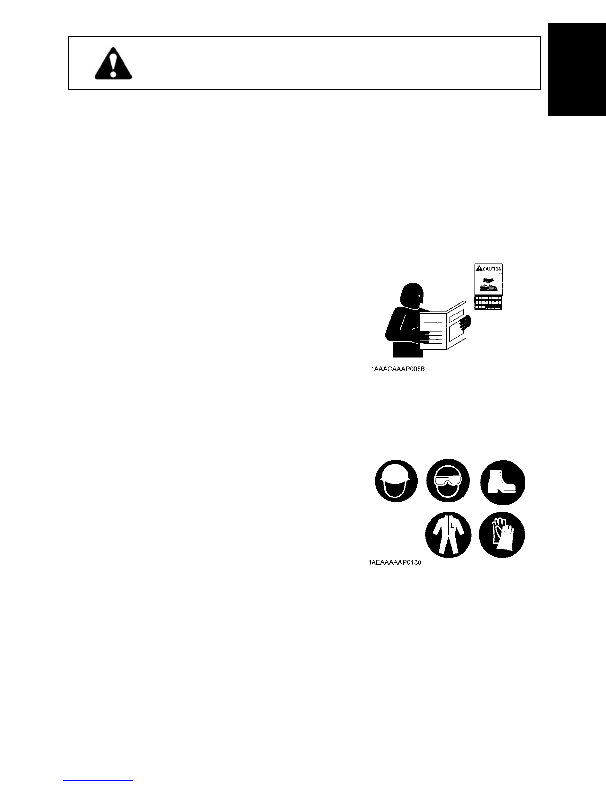
WEAR SAFETY CLOTHING
A DO NOT wear loose, torn or bulky clothing around the
generator that may catch on working controls and
projections causing personal injury.
A Use additional safety items, e.g. hard hat, safety
protections, gloves, etc., as appropriate or required.
A DO NOT operate generator or any equipment attached to
it while under the influence of alcohol, medication, or
other substances, or while fatigued.
A DO NOT wear radio or music headphones while
operating the generator.
Page 8
SAFE OPERATION2
CHECK BEFORE OPERATION & STARTING THE ENGINE
ENGLISH
A Always turn off the circuit breaker and all switches for the
electrical devices before starting the generator.
A Check the wiring and connections of the electrical
devices before starting the generator.
A Be sure to check the engine before operation. If
something is wrong with the engine, repair it immediately
and before operation.
A Keep all guards and shields in place before operating the
generator. Replace any that are damaged or missing.
A Check to see that bystanders are in a safe distance from
the generator before starting.
A Always keep the generator at least 1 m away from
buildings and other facilities.
A DO NOT allow children or livestock to approach the
generator while the engine is running.
A DO NOT start the engine by shorting across starter
terminals or bypassing normal starting circuit. The
generator may start unexpectedly causing electric shock
to others.
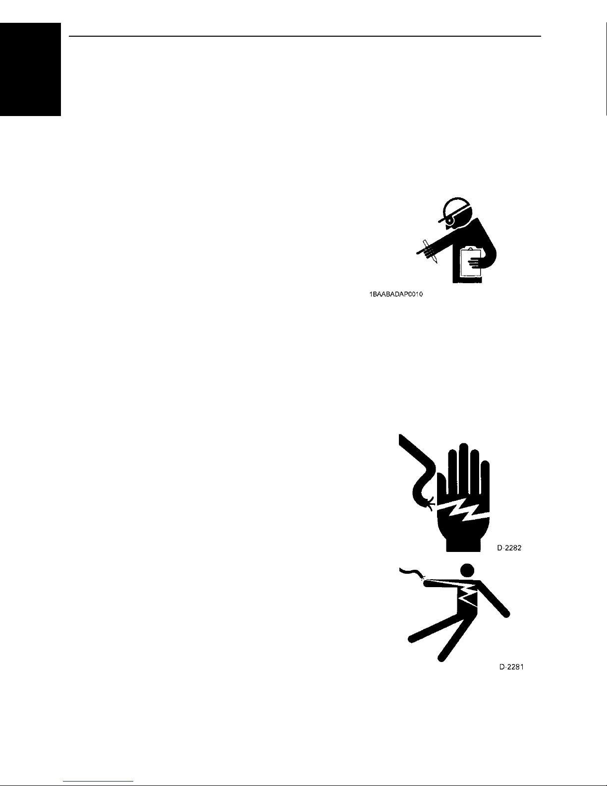
HANDLING ELECTRICAL COMPONENTS
Always exercise extra caution when handling electrical
equipment. Careless handling of electrical components can
cause serious personal injury, death by electrocution or
property damage.
A DO NOT touch the electrical system during operation.
A Connect or disconnect the load to the AC receptacles or
terminals only when the engine is stopped.
A Make certain that all power cables and wiring are in good
condition. Bare wire or frayed insulation can cause
dangerous electrical shock, burns or death.
A DO NOT use the generator in damp or wet conditions.
Handling terminals and cables with wet hands can result
in personal injury or death.
A Always shut the engine off and allow to cool before
cleaning. Use water sparingly when cleaning the outside
of the generator. Make sure that water does not splash
onto the electrical system or into the generator.
A DO NOT touch the generator with wet hands. You may
get an electric shock that can cause burns or death.
A DO NOT connect this generator to any building's
electrical system unless an isolation switch has been
installed by a licensed electrician.
A DO NOT run other generators in parallel.
Page 9
KEEP THE AREA AROUND THE ENGINE CLEAN
A Be sure to stop the engine before cleaning.
A Keep the engine clean and free of accumulated dirt,
grease and trash to avoid a fire. Store flammable fluids
away from sparks and fire.
A DO NOT stop the engine without idling. Sudden stops
can cause temperatures around the engine to rise
suddenly. Keep the engine idling for about 5 minutes
before stopping.
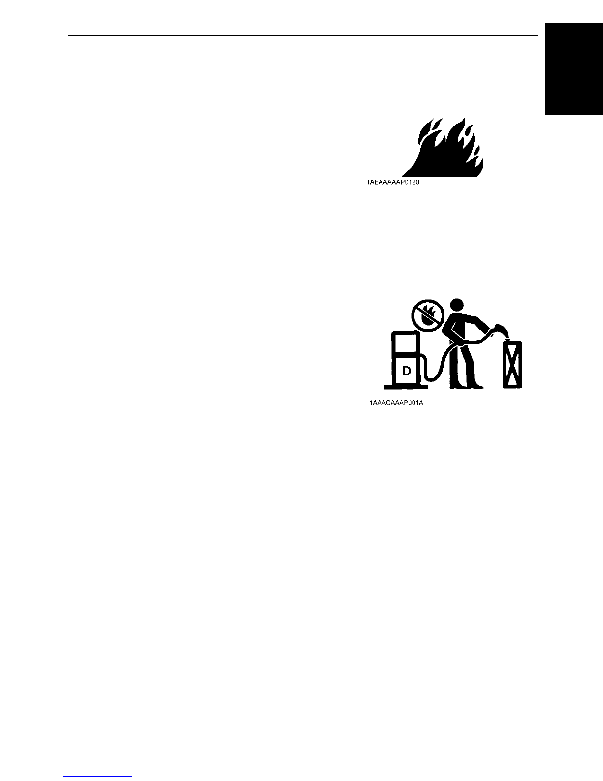
SAFE HANDLING OF FUEL AND LUBRICANTS
A Always stop the engine before refueling and/or
lubricating.
A DO NOT smoke or allow flames or sparks in the working
area. Fuel is extremely flammable and explosive under
certain conditions.
A Refuel only when the engine has cooled off. Refuel in a
well ventilated and open place. When fuel and lubricants
are spilled, clean them up before starting the engine.
A DO NOT mix gasoline or alcohol with diesel fuel. The
mixture can cause a fire and damage engine
components.
A Operate the generator on a firm and level surface only.
DO NOT tilt or move the generator while it is running
since this can cause fuel spillage.
3SAFE OPERATION
ENGLISH
Page 10
SAFE OPERATION4
EXHAUST GASES & FIRE PREVENTION
ENGLISH
A Engine exhaust fumes can be very harmful if allowing
them to accumulate. Be sure to run the engine in a well
ventilated place and where there are no people or
livestock near the generator.
A DO NOT operate the generator in a closed area such as
inside houses, warehouses, tunnels, wells, ship holds,
tanks, etc. or places without proper ventilation.
A DO NOT operate the generator where the building or
other obstructions block off air circulation or where
exhaust gas can accumulate.
A The exhaust gas from the muffler is very hot. To prevent
a fire, DO NOT expose to dry grass, papers, oil and any
other combustible materials to exhaust gas. Also, keep
the engine and muffler clean at all times.
A To avoid fire, be alert for leaks of flammables from hoses
and lines. Be sure to check for leaks from hoses or pipes,
such as fuel and engine oil by following the maintenance
check list.
A To avoid a fire, DO NOT short across power cables and
wires.
Check to see that all power cables and wiring are in good
condition.
A Keep all power connections clean and tight. Bare wire or
frayed insulation can cause a dangerous electrical shock
and personal injury.
HANDS AND BODY AWAY FROM THE ROTATING PARTS
A DO NOT operate the generator with the side covers
removed or open. Serious personal injury may result if
fingers or clothing are caught in the rotating parts.
A Be sure to stop the engine before checking or adjusting
belt tension and cooling fan.
A To avoid personal injury, keep your hands and body
away from the rotating parts, such as cooling fan, V-belt,
fan drive V-belt, pulleys or flywheel.
A DO NOT run the engine with installed safety guards
detached. Install safety guards securely before
operation.
Page 11
ESCAPING FLUID
A Relieve all pressure in the oil and the cooling systems
before any lines, fittings or related items are removed or
disconnected.
A Be alert for possible pressure when disconnecting any
device from a system that utilizes pressure.
DO NOT check for pressure leaks with your hand.
High pressure oil or fuel can cause serious personal
injury.
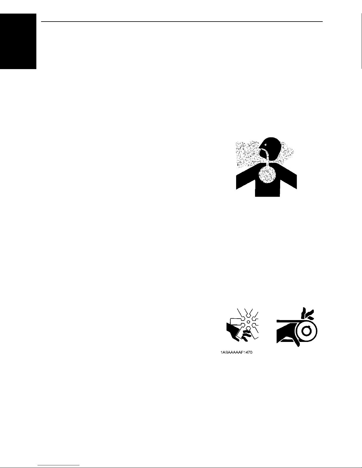
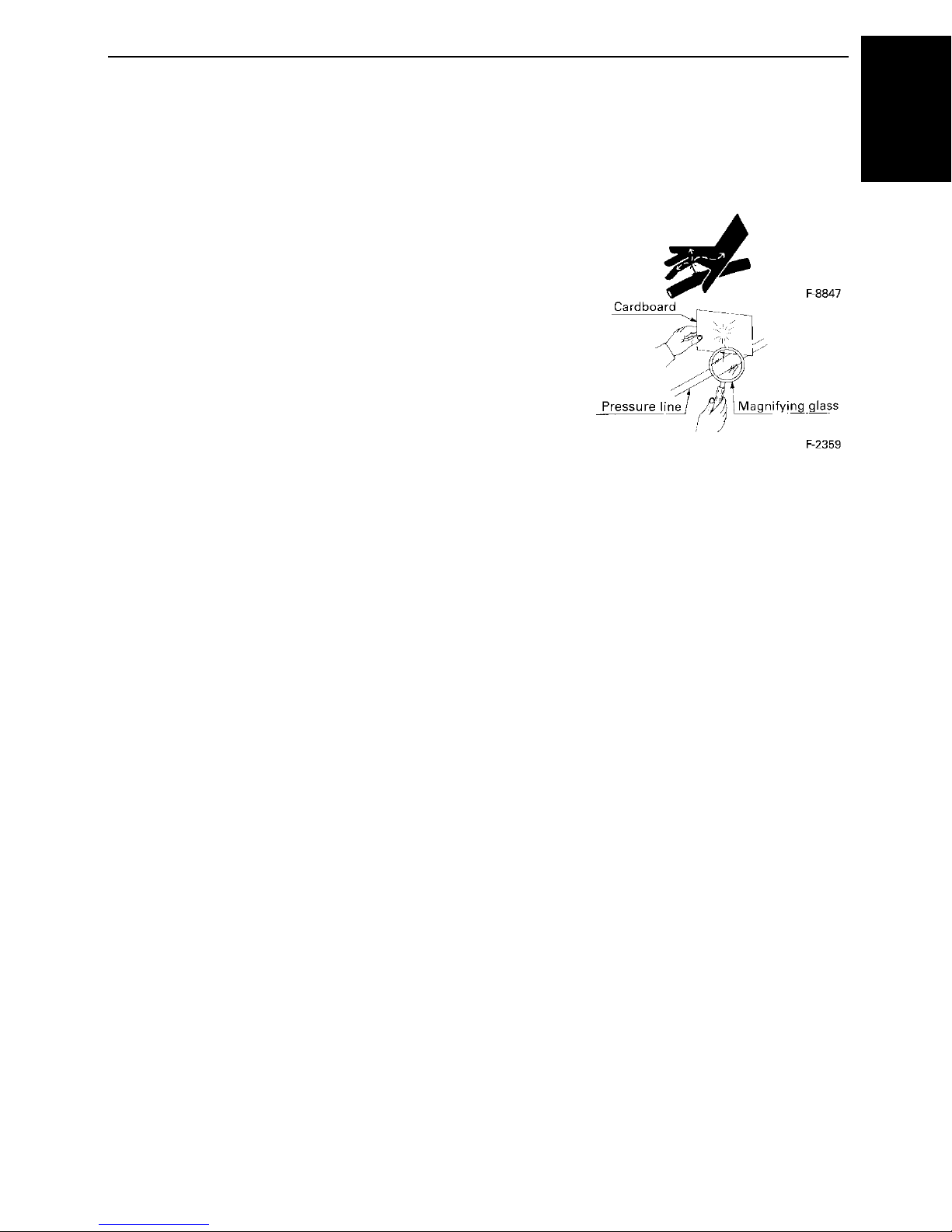
A Escaping fluid under pressure has sufficient force to
penetrate skin causing serious personal injury.
A Fluid escaping from pinholes may be invisible.
Use a piece of cardboard or wood to search for
suspected leaks: DO NOT use hands or body. Use safety
goggles or other eye protection when checking for leaks.
A If injured by escaping fluid, see a medical doctor at once.
This fluid can produce gangrene or severe allergic
reaction.
5SAFE OPERATION
ENGLISH
Page 12
SAFE OPERATION6
CAUTIONS AGAINST BURNS & BATTERY EXPLOSION
ENGLISH
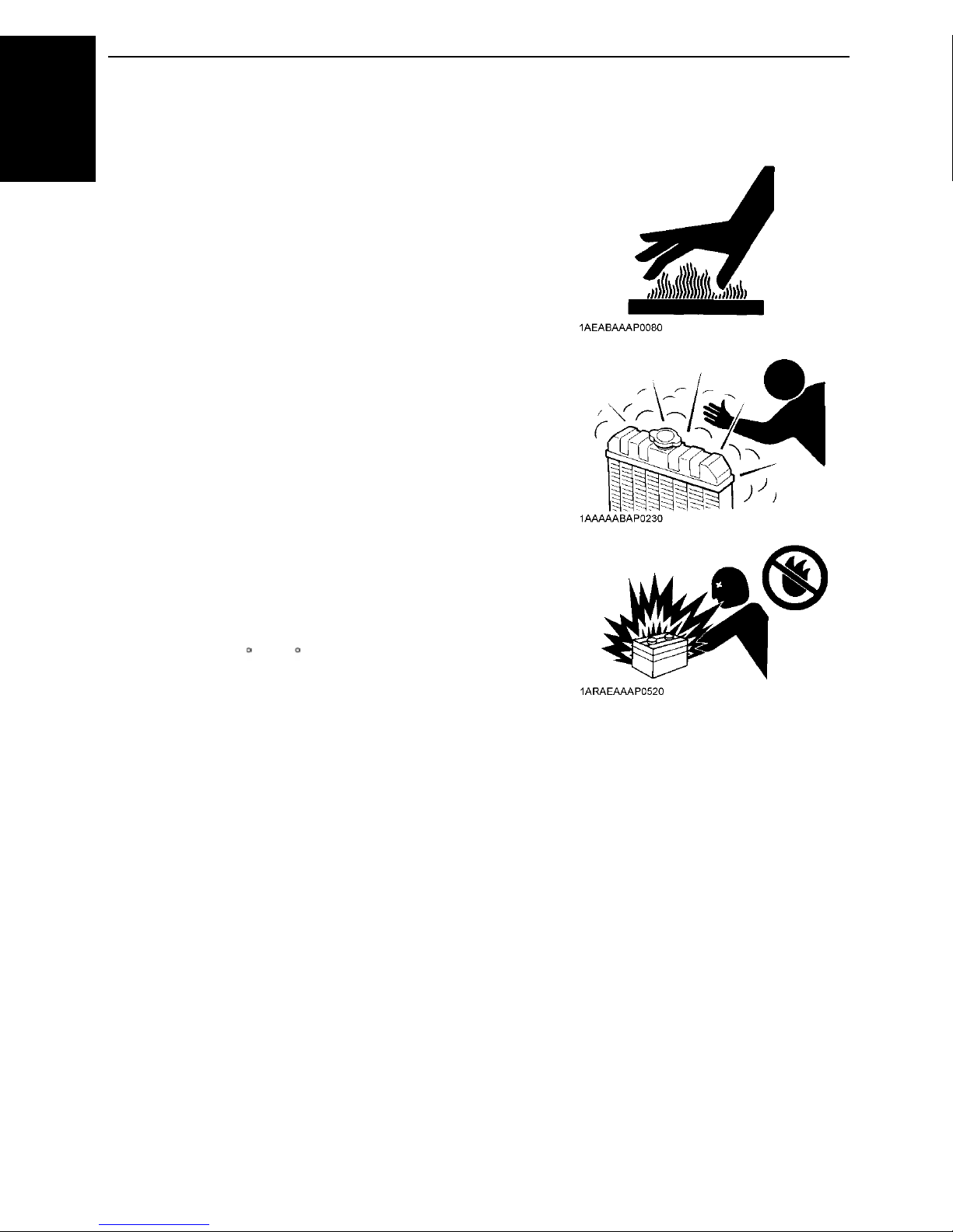
A To avoid burns, be alert for hot components, e.g. muffler,
muffler cover, radiator, pipes, hoses, engine body,
coolant, engine oil, etc. during operation and just after the
engine has been shut off.
A DO NOT remove the radiator cap while the engine is
running or immediately after stopping. Otherwise hot
water from the radiator will escape under pressure
causing injury by scalding. Wait for more than 10 minutes
to allow the coolant to cool down, before removing the
cap.
A Make sure to close the drain valve of coolant and engine
oil, close radiator pressure cap and tighten hose clamps
before operating. If any of these parts are taken off, or left
loose, serious personal injury can result.
A The battery presents an explosive hazard. When the
battery is being activated, hydrogen and oxygen gases
are extremely explosive.
A Keep sparks and open flames away from the battery,
especially when charging the battery. DO NOT strike a
match near the battery.
A DO NOT check battery charge by placing a metal object
across the terminals. Use a voltmeter or hydrometer.
A DO NOT charge battery if frozen, there is a risk of
explosion. When battery is frozen, allow the battery to
warm up to 16 C (61 F) before charging.
A DO NOT use or charge the battery if its fluid level is below
the LOWER (lower limit level) mark (refillable type battery
only).
Otherwise, the component parts may deteriorate earlier
than expected, which may shorten the service life or
cause an explosion. Add distilled water until the fluid level
Page 13
CONDUCTING SAFETY CHECKS & MAINTENANCE
A Know how to stop the generator quickly, and understand
operation of all the controls. DO NOT permit anyone to
operate the generator without proper instruction.
A When checking engine or servicing, place the generator
in an open area and level ground. DO NOT work on
anything that is supported ONLY by lift jacks or a hoist.
Always use blocks or safety stands to support the
generator before servicing.
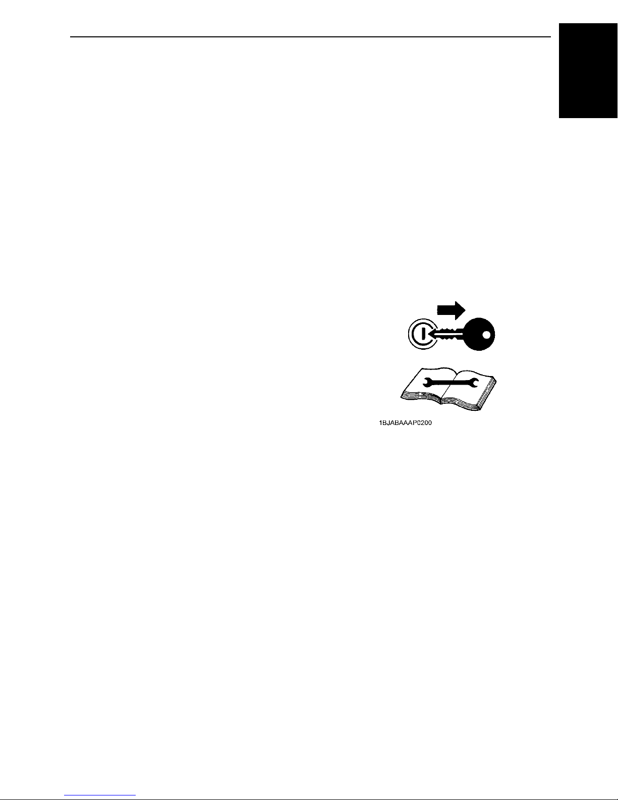
A Detach the battery from the generator before conducting
service.
Put a “DO NOT OPERATE!” tag on the key switch and
remove the key to avoid accidental starting.
A To avoid sparks from an accidental short circuit, always
disconnect the battery’s ground cable (-) first and
connect it last.
A Sulfuric acid in battery electrolyte is poisonous. It is
strong enough to burn skins and clothing and cause
blindness if splashed into eyes. Keep electrolyte away
from eyes, hands and clothing.
If you spill electrolyte on yourself, flush with water, and
get medical attention immediately.
A Be sure to stop the engine and remove the key when
conducting daily and periodic maintenance, servicing
and cleaning.
A Check or conduct maintenance after the engine, coolant,
muffler, or muffler cover have cooled off completely.
A Always use the appropriate lifting equipment and make
sure safety stands are in good condition when performing
any service work. Make sure that you understand how to
use the equipment before servicing.
A Use ONLY the correct engine flywheel rotating
techniques for manually rotating the engine. DO NOT
attempt to rotate the engine by pulling or prying on the
cooling fan or V-belt. This practice can cause serious
personal injury or premature machine damage to the
cooling fan.
A Replace fuel, lubricant and coolant hoses with their hose
clamps every 2 years or earlier if required. They are
made of rubber and deteriorate over time whether used
or not.
A When servicing is performed together by two or more
persons, take care to perform all work safely.
A Keep first aid kit and fire extinguisher handy at all times.
7SAFE OPERATION
ENGLISH
Page 14
SAFE OPERATION8
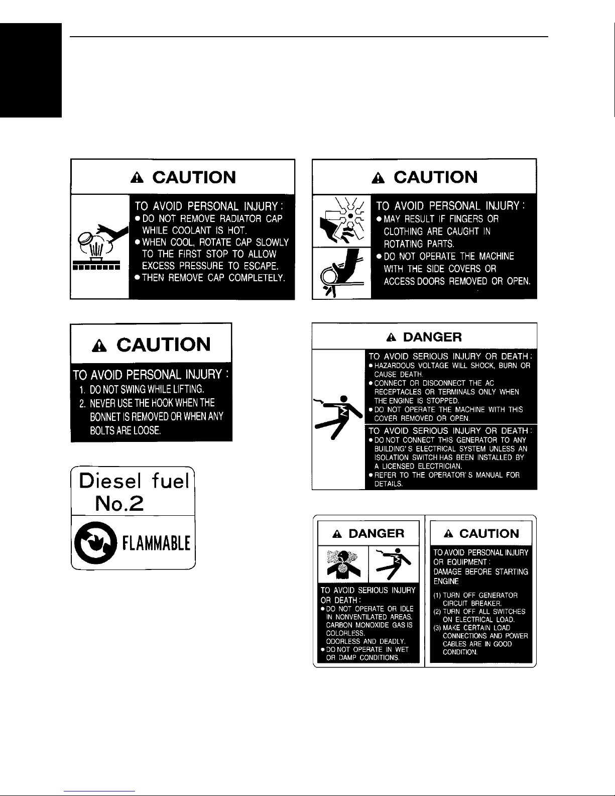
DANGER, WARNING AND CAUTION LABELS
ENGLISH
Pay special attention to all labels on the generator.
Refer to following representations for labels used on the J-Series Generator. Labels are
available individually from your KUBOTA Dealer.
(1) Part No. G3907-8832-0 (2) Part No. G3907-8830-0
(3) Part No. G3907-8836-0 (4) Part No. G3907-8831-0
(5) Part No. 18901-5090-2
(6) Part No. G3907-8824-0
Page 15

(7) Part No. 18620-8806-0 (8) Part No. G3907-8833-0
9SAFE OPERATION
ENGLISH
For the Z482 or D722-mounted machines only.
Page 16

SAFE OPERATION10
CARE OF DANGER, WARNING AND CAUTION LABELS
ENGLISH
1. Keep danger, warning and caution labels clean and free from obstructing material.
2. Clean danger, warning and caution labels with soap and water, dry with a soft cloth.
3. Replace damaged or missing danger, warning and caution labels with new labels from your
local KUBOTA Dealer.
4. If a component with danger, warning and caution label(s) affixed is replaced with new part,
make sure new label(s) is (are) attached in the same location(s) as the replaced component.
5. Mount new danger, warning and caution labels by applying on a clean dry surface and
pressing any bubbles to outside edge.
Page 17
SERVICING OF GENERATOR
Your dealer is interested in your new generator and has
the desire to help you get the most value from it. After
reading this manual thoroughly, you will find that you can
do some of the regular maintenance yourself.
However, when in need of parts or major service, be sure
to see your KUBOTA Dealer.
For service, contact the KUBOTA Dealership from which
you purchased your generator or your local KUBOTA
Dealer.
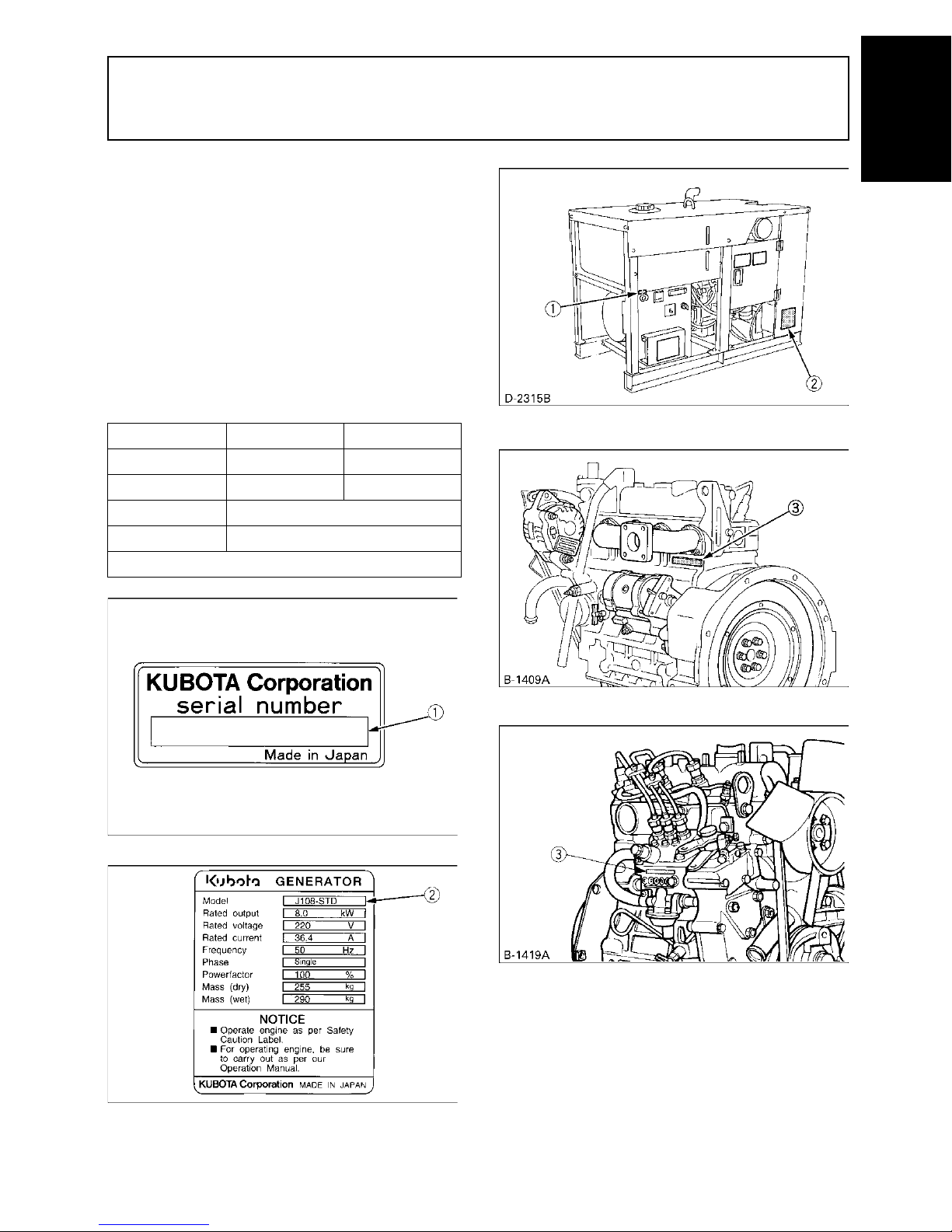
When in need of parts, be prepared to give your dealer
the generator and engine serial numbers.
Locate the serial numbers now and record them in the
space provided below.
1SERVICING OF GENERATOR
ENGLISH
Model Serial No.
Generator
Engine
Date of Purchase
Name of Dealer
(To be filled in by purchaser)
[Engine model : D1005, V1305]
[Engine model : Z482, D722]
(1) Generator serial number
(2) Generator model
(3) Engine serial number
Page 18
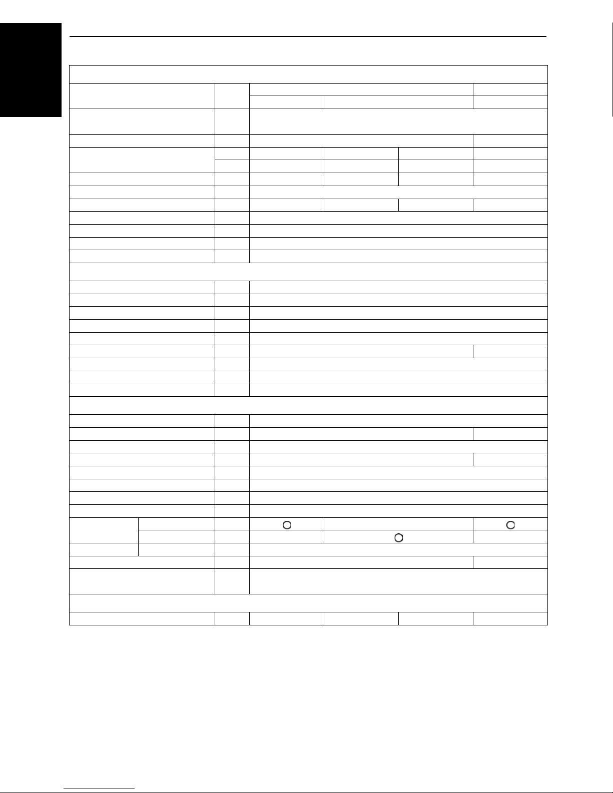
2 SPECIFICATIONS
SPECIFICATIONS
ENGLISH
MOKUJIYOU
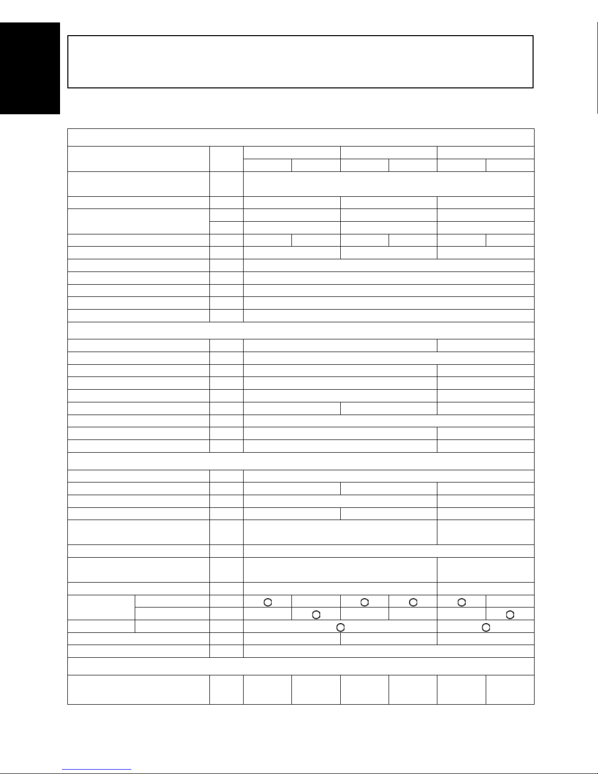
B1 Phase Type
GENERATOR
Model Unit
Design
Frequency Hz 50 60 50
Rated Output (COP)
Rated Voltage V 220 240 110/220 127/220 220 240
Phase & Wire φ-w 1-2 1-3 1-2
Power Factor % 100
No. of Poles - 2
Insulation - Rotary coil: Class F, Stator coil: Class B
Voltage Regulation % 7 (No load to full load)
Type of Coupling Direct coupled
DIESEL ENGINE
Model Z482-B-SEC D722-B-SEC
Design Vertical, water-cooled, 4-cycle diesel engine
No. of cylinders 2 3
Bore x stroke mm φ67 x 68 φ67 x 68
Displacement L 0.479 0.719
Engine speed rpm 3000 3600 3000
Lubricating Oil API service class CD or higher
Oil capacity L 2.2 3.4
Coolant capacity L 2.3 3.0
SET
kVA 5.5 6.5 8
kW 5.5 6.5 8
J106 J107 J108
-STD -AUS -STD -SA -STD -AUS
Salient-pole, revolving-field AC generator
(AVR system with separate and self-excitation brush)
Fuel Diesel fuel No. 2 (ASTM D975)
Fuel consumption (at full load) L 2.3 2.8 3.2
Fuel tank capacity L 37 37
Continuous Operating Hours hrs 16.0 13.2 11.5
Battery (V x Ah/5Hr)
Starting System Electric
L x W x H (with wheel) mm
Approx Net Wt. kg 225 255
Output
Option Caster Sound Level (full load at 7m) dB(A) 74.0 76.0 75.0
Emergency Stop System - In case of abnormal: Oil pressure, water temperature
AMPS
AMPS A 25.0 22.9
Terminal - - Receptacle - - - - -
38B20R
(12V x 28Ah)
923 x 593 x 860
(1037)
59.1/
29.5
51.2/
29.5
55B24R
(12V x 36Ah)
995 x 593 x 860
(1037)
36.4 33.3
Page 19

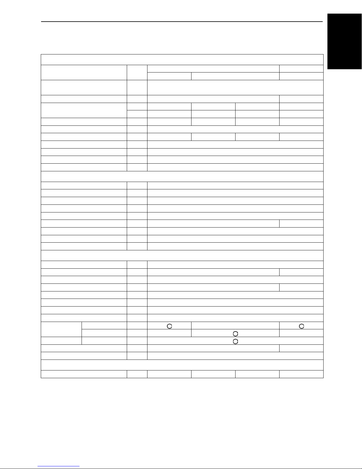
GENERATOR
3SPECIFICATIONS
Model Unit
Design
Frequency Hz 60 50 60
kVA 10 12 14
Rated Output (COP)
kW 10 12 14
Rated Voltage V 110/220 127/220 220 240 110/220 127/220
Phase & Wire φ-w 1-3 1-2 1-3
Power Factor % 100
No. of Poles - 2
Insulation - Rotary coil: Class F, Stator coil: Class B
Voltage Regulation %
Type of Coupling Direct coupled
DIESEL ENGINE
Model D722-B-SEC D1005-BG-SEC
Design Vertical, water-cooled, 4-cycle diesel engine
No. of cylinders 3
Bore x stroke mm φ67 x 68 φ76 x 73.6
Displacement L 0.719 1.001
Engine speed rpm 3600 3000 3600
Lubricating Oil API service class CD or higher
Oil capacity L 3.4 4.3
Coolant capacity L 3.0 3.3
SET
J110 J112 J114
-STD -SA -STD -AUS -STD -SA
Salient-pole, revolving-field AC generator
(AVR system with separate and self-excitation brush)
11.5/
14.0
11.5/
14.0
7 (No load to full
load)
8 (No load to full load)
ENGLISH
Fuel Diesel fuel No. 2 (ASTM D975)
Fuel consumption (at full load) L 4.2 4.5 5.8
Fuel tank capacity L 37 79
Continuous Operating Hours hrs 8.5 17.0 13.5
Battery (V x Ah/5Hr)
Starting System Electric
L x W x H (with wheel) mm
Approx Net Wt. kg 255 340
Output
Option Caster - Sound Level (full load at 7m) dB(A) 76.5 76.5 81.0
Emergency Stop System -
AMPS
AMPS A
Terminal - Receptacle---- --
55B24R
(12V x 36Ah)
995 x 593 x 860
(1037)
In case of
abnormal: Oil
pressure, water
temperature
90.9/
45.5
78.7/
45.5
In case of abnormal: Oil pressure, water
temperature, fan belt broken
54.5 50.0
80D26R(S)
(12V x 55Ah)
1215 x 611 x 922
63.6 x 2
/63.6
90.6/
63.6
Page 20

4 SPECIFICATIONS
GENERATOR
Model Unit
ENGLISH
Design
Frequency Hz 50 60
kVA 16 18.8 11.5/18.8
Rated Output (COP)
kW 16 18.8 11.5/18.8
Rated Voltage V 220 240 110/220 127/220
Phase & Wire φ-w 1-2 1-3
Power Factor % 100
No. of Poles - 2
Insulation - Rotary coil: Class F, Stator coil: Class B
Voltage Regulation % 8 (No load to full load)
Type of Coupling Direct coupled
DIESEL ENGINE
Model V1305-BG-SEC
Design Vertical, water-cooled, 4-cycle diesel engine
No. of cylinders 4
Bore x stroke mm φ76 x 73.6
Displacement L 1.335
Engine speed rpm 3000 3600
Lubricating Oil API service class CD or higher
Oil capacity L 5.7
Coolant capacity L 3.5
SET
-STD -AUS -STD -SA
(AVR system with separate and self-excitation brush)
J116 J119
Salient-pole, revolving-field AC generator
Fuel Diesel fuel No. 2 (ASTM D975)
Fuel consumption (at full load) L 6.0 7.5
Fuel tank capacity L 79
Continuous Operating Hours hrs 13.0 10.5
Battery (V x Ah/5Hr) 80D26R(S) (12V x 55Ah)
Starting System Electric
L x W x H (with wheel) mm 1300 x 611 x 922
Approx Net Wt. kg 380
Output
Option Caster - Sound Level (full load at 7m) dB(A) 77.5 82.0
Emergency Stop System -
AMPS
AMPS A 72.7 66.7
Terminal - Receptacle - - - -
In case of abnormal:
Oil pressure, water temperature, fan belt broken
85.5 x 2
/85.5
90.6/85.5
Page 21
B3 Phase Type
5SPECIFICATIONS
GENERATOR
Model Unit
Design
Frequency Hz 50 60
Rated Output (COP)
Rated Voltage V 380 415 240 220
Phase & Wire φ-w 3-4
Power Factor % 80 80 100 80
No. of Poles - 2
Insulation - Rotary coil: Class F, Stator coil: Class B
Voltage Regulation % 8 (No load to full load)
Type of Coupling Direct coupled
DIESEL ENGINE
Model D722-B-SEC
Design Vertical, water-cooled, 4-cycle diesel engine
No. of cylinders 3
Bore x stroke mm φ67 x 68
Displacement L 0.719
Engine speed rpm 3000 3600
Lubricating Oil API service class CD or higher
Oil capacity L 3.4
Coolant capacity L 3.0
SET
kVA 10 10 6 12.5
kW 8 8 6 10
-STD -AUS -STD
Salient-pole, revolving-field AC generator
(AVR system with separate and self-excitation brush)
J310 J313
ENGLISH
Fuel Diesel fuel No. 2 (ASTM D975)
Fuel consumption (at full load) L 3.2 4.2
Fuel tank capacity L 37
Continuous Operating Hours hrs 11.5 8.5
Battery (V x Ah/5Hr) 55B24R (12V x 36Ah)
Starting System Electric
L x W x H (with wheel) mm 995 x 593 x 860 (1037)
Approx Net Wt. kg 255
Output
Option Caster Sound Level (full load at 7m) dB(A) 75.0 76.5
Emergency Stop System - In case of abnormal: Oil pressure, water temperature
AMPS
AMPS A 15.2 13.9 8.3 x 3 32.8
Terminal - Receptacle - - -
Page 22
6 SPECIFICATIONS
GENERATOR
Model Unit
ENGLISH
Design
Frequency Hz 50 60
Rated Output (COP)
Rated Voltage V 380 415 240 220
Phase & Wire φ-w 3-4
Power Factor % 80 80 100 80
No. of Poles - 2
Insulation - Rotary coil: Class F, Stator coil: Class B
Voltage Regulation % 8 (No load to full load)
Type of Coupling Direct coupled
DIESEL ENGINE
Model D1005-BG-SEC
Design Vertical, water-cooled, 4-cycle diesel engine
No. of cylinders 3
Bore x stroke mm φ76 x73.6
Displacement L 1.001
Engine speed rpm 3000 3600
Lubricating Oil API service class CD or higher
Oil capacity L 4.3
Coolant capacity L 3.3
SET
kVA 15 15 9 17.5
kW 12 12 9 14
-STD -AUS -STD
Salient-pole, revolving-field AC generator
(AVR system with separate and self-excitation brush)
J315 J318
Fuel Diesel fuel No. 2 (ASTM D975)
Fuel consumption (at full load) L 4.5 5.8
Fuel tank capacity L 79
Continuous Operating Hours hrs 17.0 13.5
Battery (V x Ah/5Hr) 80D26R(S) (12V x 55Ah)
Starting System Electric
L x W x H (with wheel) mm 1215 x 611 x 922
Approx Net Wt. kg 340
Output
Option Caster - Sound Level (full load at 7m) dB(A) 76.5 81.0
Emergency Stop System -
AMPS
AMPS A 22.8 20.9 12.5 x 3 45.9
Terminal - Receptacle - - -
In case of abnormal:
Oil pressure, water temperature, fan belt broken
Page 23

GENERATOR
7SPECIFICATIONS
Model Unit
Design
Frequency Hz 50 60
Rated Output (COP)
Rated Voltage V 380 415 240 220
Phase & Wire φ-w 3-4
Power Factor % 80 80 100 80
No. of Poles - 2
Insulation - Rotary coil: Class F, Stator coil: Class B
Voltage Regulation % 8 (No load to full load)
Type of Coupling Direct coupled
DIESEL ENGINE
Model V1305-BG-SEC
Design Vertical, water-cooled, 4-cycle diesel engine
No. of cylinders 4
Bore x stroke mm φ76 x73.6
Displacement L 1.335
Engine speed rpm 3000 3600
Lubricating Oil API service class CD or higher
Oil capacity L 5.7
Coolant capacity L 3.5
SET
kVA 20 20 10.8 23.5
kW 16 16 10.8 18.8
-STD -AUS -STD
Salient-pole, revolving-field AC generator
(AVR system with separate and self-excitation brush)
J320 J324
ENGLISH
Fuel Diesel fuel No. 2 (ASTM D975)
Fuel consumption (at full load) L 6.0 7.5
Fuel tank capacity L 79
Continuous Operating Hours hrs 13.0 10.5
Battery (V x Ah/5Hr) 80D26R(S) (12V x 55Ah)
Starting System Electric
L x W x H (with wheel) mm 1300 x 611 x 922
Approx Net Wt. kg 380
Output
Option Caster - Sound Level (full load at 7m) dB(A) 77.5 82.0
Emergency Stop System -
AMPS
AMPS A 30.4 27.8 15 x 3 61.7
Terminal - Receptacle - - -
In case of abnormal:
Oil pressure, water temperature, fan belt broken
Page 24
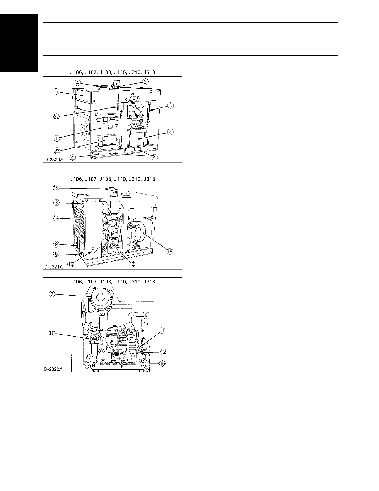
8 NOMENCLATURE
NOMENCLATURE
ENGLISH
MOKUJIYOU
(1) Control panel
(2) Hook
(3) Coolant filling port
(4) Fuel tank cap
(5) Door
(6) Engine oil drain plug
(7) Air cleaner
(8) Battery
(9) Reserve tank
(10) Fuel cock
(11) Engine oil port
(12) Oil dipstick
(13) Oil filter cartridge
(14) Radiator
(15) Coolant drain plug (radiator)
(16) Coolant drain plug (engine)
(17) Fuel tank
(18) Generator
(19) Muffler
(20) Base
(21) Fork pockets
(22) Fuel gauge
(23) Terminal cover
Page 25
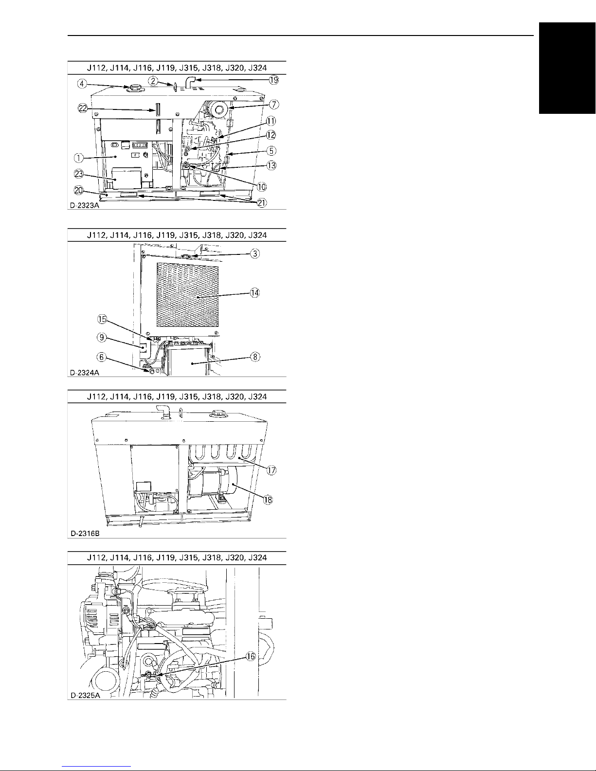
(1) Control panel
(2) Hook
(3) Coolant filling port
(4) Fuel tank cap
(5) Door
(6) Engine oil drain plug
(7) Air cleaner
(8) Battery
(9) Reserve tank
(10) Fuel cock
(11) Engine oil port
(12) Oil dipstick
(13) Oil filter cartridge
(14) Radiator
(15) Coolant drain plug (radiator)
(16) Coolant drain plug (engine)
(17) Fuel tank
(18) Generator
(19) Muffler
(20) Base
(21) Fork pockets
(22) Fuel gauge
(23) Terminal cover
9NOMENCLATURE
ENGLISH
Page 26
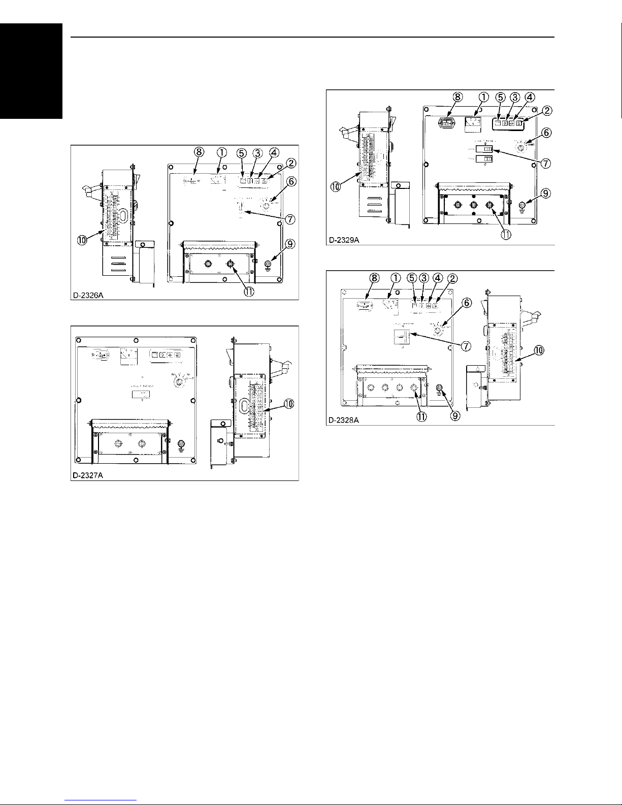
NOMENCLATURE10
BControl Panel
ENGLISH
Standard Model
C 1 Phase Type (220V Type)
[J106-STD, J108-STD]
[J112-STD, J116-STD]
C 1 Phase Type (110V/220V Dual voltage type)
[J107-STD, J110-STD]
[J114-STD, J119-STD]
(1) A.C. Voltmeter
(2) Glow plug lamp
(3) Water temperature lamp
(4) Oil pressure lamp
(5) Battery charge lamp
(6) Main switch (key)
(7) Circuit breaker
(8) Hour meter
(9) Ground terminal
(10) Terminal (Autostart unit)
(11) Terminals (output)
(1) A.C. Voltmeter
(2) Glow plug lamp
(3) Water temperature lamp
(4) Oil pressure lamp
(5) Battery charge lamp
(6) Main switch (key)
(7) Circuit breaker
(8) Hour meter
(9) Ground terminal
(10) Terminal (Autostart unit)
(11) Terminals (output)
Page 27

11NOMENCLATURE
C 1 Phase Type (127V/220V Dual voltage type)
[J107-SA, J110-SA]
[J114-SA, J119-SA]
C 3 Phase Type
[J310-STD, J313-STD]
ENGLISH
[J315-STD, J318-STD, J320-STD, J324-STD]
(1) A.C. Voltmeter
(2) Glow plug lamp
(3) Water temperature lamp
(4) Oil pressure lamp
(5) Battery charge lamp
(6) Main switch (key)
(7) Circuit breaker
(8) Hour meter
(9) Ground terminal
(10) Terminal (Autostart unit)
(11) Terminals (output)
(1) A.C. Voltmeter
(2) Glow plug lamp
(3) Water temperature lamp
(4) Oil pressure lamp
(5) Battery charge lamp
(6) Main switch (key)
(7) Circuit breaker
(8) Hour meter
(9) Ground terminal
(10) Terminal (Autostart unit)
(11) Terminals (output)
Page 28
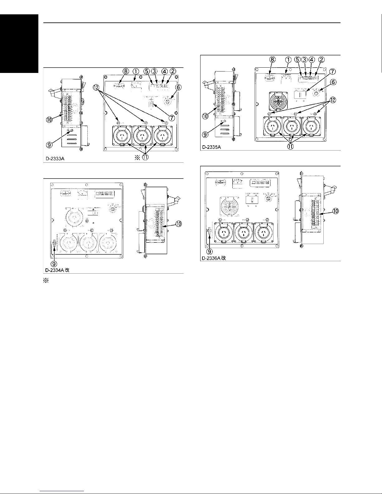
NOMENCLATURE12
AUS Model
C 1 Phase Type
ENGLISH
[J106-AUS, J108-AUS]
[J112-AUS, J116-AUS]
C 3 Phase Type
[J310-AUS]
[J315-AUS, J320-AUS]
The J106-AUS is equipped with 2 receptacles.
(1) A.C. Voltmeter
(2) Glow plug lamp
(3) Water temperature lamp
(4) Oil pressure lamp
(5) Battery charge lamp
(6) Main switch (key)
(7) Circuit breaker
(8) Hour meter
(9) Ground terminal
(10) Terminal (Autostart unit)
(11) Receptacles
(12) Circuit protector (Receptacle)
(1) A.C. Voltmeter
(2) Glow plug lamp
(3) Water temperature lamp
(4) Oil pressure lamp
(5) Battery charge lamp
(6) Main switch (key)
(7) Circuit breaker
(8) Hour meter
(9) Ground terminal
(10) Terminal (Autostart unit)
(11) Receptacles
(12) Circuit protector (Receptacle)
Page 29

13NOMENCLATURE
BEasy Checker
When an abnormal condition occurs with a part monitored
by the easy checker while the engine is running, a lamp
flashes to warn the operator of the impending trouble.
(1) Charge warning lamp
(2) Water temperature-overheat warning lamp, flashes on when
cooling water rises to 112 to 118 C.
(3) Engine oil pressure drop warning lamp, flashes on below 39
to 59 kPa (0.4 to 0.6 kgf/cm ) oil pressure.
(4) Glow plug lamp
BControl Box
ENGLISH
(1) Excitation unit
(2) Emergency relay
(3) Starter relay
(4) Glow relay
(5) Glow lamp timer
(6) Relay
(7) Relay (Solenoid)
Page 30

14 PREPARATION TO SUPPLY THE ELECTRIC POWER
PREPARATION TO SUPPLY THE ELECTRIC POWER
ENGLISH
1. Generator grounding
The end user, equipment owner or operator must contact
his local, state, county or municipal electric code
department to determine the approved generator
grounding method to be used in his application or
location.
Recommendations in the NEC (National Electrical Code),
NFPA (National Fire Protection Association),
AUSTRALIAN STANDARDS and OSHA (Occupational
Safety and Health Administration) regulations must be
followed to assure compliance and safe operation.
Always be sure to ground (earth) the generator terminals
to comply with the local, state, national or OSHA
requirements.
One possible connection method for construction site use
is as follows:
(1) Generator ground terminal (A) #6AWG
Flexible copper ground
connection
(B) Metal ground rod or
building cold water pipe
system per N.E.C. code
Page 31

15PREPARATION TO SUPPLY THE ELECTRIC POWER
Typical
Apparatus
Light and
heaters
Commutator
motor
Induction
motor
J106 5.5 kW 2.8 kW 0.8 kW
3.3 kW
4.0 kW
5.0 kW
6.0 kW
7.0 kW
8.0 kW
9.4 kW
5.0 kW
6.3 kW
7.5 kW
8.8 kW
10.0 kW
11.8 kW
0.8 kW
1.2 kW
1.6 kW
1.6 kW
2 kW
2.4 kW
2.4 kW
3.7 kW
3.7 kW
4.4 kW
5.5 kW
5.9 kW
7.4 kW
6.5 kW
8 kW
10 kW
12 kW
14 kW
16 kW
18.8 kW
8 kW
10 kW
12 kW
14 kW
16 kW
18.8 kW
J107
J108
J110
J112
J114
J116
J119
J310
J313
J315
J318
J320
J324
AC devices
Electric power (W)
= Voltage (V) Current (A) Power factor
Load type Power factor
Single-phase induction motors 0.4 to 0.75
3-phase induction motors 0.65 to 0.85
Electric heaters, incandescent
lamps
1.0
AC arc welder 0.4 to 0.6
Commutator motor 0.8 to 0.95
Fluorescent lamps, mercury
lamps
0.4 to 0.9
Motor input (kVA)
Motor output (kW)
Motor efficiency power factor
=
2. Recommended capacity of electrical
devices
APPLICATION RANGE
You can operate the J-series generator in the following
range.
A Connecting a motor.
When connecting to a line starting motor, these
generators may be used to start a submerged pump of
3.7kW, 5.5kW, 7.5kW (three phase). When starting
the motor, the voltage drops immediately. The circuit
may be opened if an electromagnetic switch is
connected to the same circuit. When connecting two
motors or more, make sure the total current capacity
of the motors does not exceed the total rated current.
A Connecting to lights and electric heaters.
When connecting to lights or electric heaters, the
generator can be used up to the rated capacity. When
using a single phase, it can be used up to the rated
current.
A Power factor calculations.
The power factor calculation is used to determine
input of the electrical devices.
Power factors of commonly used devices are listed in the
following table.
ENGLISH
A Keep an inverter load below 50% of the generator
capacity.
A Make sure that total active mercury lamp load is below
30% or so of the generator capacity. Turn on the
mercury lamps one by one. Be careful not to turn off
the lamps and on again immediately. The generator
voltage may rise to extremely high levels and the AVR
may get damaged.
A Before turning on the lamps again, wait for 10 minutes
or so until the lamps cool down enough.
A The data shown above is only a guideline to
approximate load capacities and may vary from
generator model to generator model, with different
types of loads at rated outputs. These values may be
different from actual applications because of the input
characteristics peculiar to each load.
A Ordinarily, a motor is rated in kW. This does not refer
to motor output.
A If a lighting system is employed together with some
types of computers and inverter air-conditioners and/
or the regulated power supply for TV sets, the lights
might suffer flickering. This phenomenon does not
indicate a fault of the generator: it is caused by poor
matching between the above-mentioned regulated
power supply and the generator's automatic voltage
regulator. In such a case, modify the load combination
to eliminate the flickering.
Page 32

16 CONNECTING THE LOAD
CONNECTING THE LOAD
ENGLISH
MOKUJIYOU
BConnection Notes
To avoid personal injury:
A Before the generator can be
connected to a building’s electrical
system, a licensed electrician must
install an isolation (transfer) switch
in the building’s main fuse box. The
switch is the connection point for
generator power and allows
selection of generator or main line
power to the building. This will
prevent the generator from charging
the main power line (backfeeding)
when the main power supply has
failed or has been turned off for line
repair. Backfeeding can electrocute
or injure line maintenance personnel.
Also, generator and building
electrical system damage can occur
when normal operating power
returns if unit is used without an
isolation switch.
(1) Circuit breaker
(2) Terminals (output)
(3) Cover lock bolt
C Single phase 2 terminals type
i ) J106-STD, J108-STD, J112-STD, J116-STD
50Hz 220V
[Single phase]
1. Avoid connecting the generator to commercial power
outlet.
2. Avoid connecting the generator in parallel with any
other generator.
BConnecting the Load (Standard Model)
To avoid personal injury:
A Connect or disconnect the load to
the AC receptacles or terminals only
when the engine is stopped.
A For your safety, close the terminal
cover after connecting the load.
A For your safety, secure the cover
with the lock bolts.
1. Turn OFF the circuit breaker on the control panel.
2. Connect the load to the A.C. output terminals.
3. Be sure to close the terminal cover after connecting
the load.
(1) Light
(2) Television
(3) Air conditioner
(4) Electric drill
(5) Motor pump
Page 33

17CONNECTING THE LOAD
C Single phase 3 terminals type (1P3W type)
(Dual voltage type)
i ) J107-STD, J110-STD
60Hz 110/220V
ii) J107-SA, J110-SA, J114-SA, J119-SA
60Hz 127/220V
[Single phase]
(1) Light
(2) Television
(3) Air conditioner
(4) Electric drill
(5) Motor pump
C Single phase 4 terminals type (1P4W type)
(Dual voltage type)
i ) J114-STD, J119-STD
60Hz 110/220V
[Single phase]
C 3 phase and single phase 4 terminals type
A For 3 phase power source
i ) J310-STD, J315-STD, J320-STD
50Hz 380V Use (W)-(V)-(U)
ii) J313-STD, J318-STD, J324-STD
60Hz 220V Use (W)-(V)-(U)
[Three phase]
(1) Motor
A For single phase power source
i ) J310-STD, J315-STD, J320-STD
50Hz 2 20V Use (O)- (U), (O)-( V), ( O)-( W )
ii) J313-STD, J318-STD, J324-STD
60Hz 1 27V Use (O)- (U), (O)-( V), ( O)-( W )
[Single phase]
ENGLISH
(1) Light
(2) Television
(3) Air conditioner
(4) Electric drill
(5) Motor pump
(1) Light
(2) Television
(3) Air conditioner
Page 34

CONNECTING THE LOAD18
[ A list of receptacles ]
Single Phase 3 Phase
Model 56S0315 56S0310 56S0520 56S0532
J106-
AUS
2000
J108-
AUS
3000
J112-
J116-
AUS
4000
J310-
AUS
0310
J315-
J320-
AUS
3001
A For single phase power source
i ) J310-STD, J315-STD, J320-STD
50Hz 380V single phase Use (U)-(V), (V)-(W), (W)-(U)
ENGLISH
ii) J313-STD, J318-STD, J324-STD
60Hz 220V single phase Use (U)-(V), (V)-(W), (W)-(U)
[Single phase]
(1) Electric drill
(2) Motor pump
(3) Air conditioner
BConnecting the Load (AUS Model)
2. Connect the load to the A.C. receptacles.
[Receptacles use]
To avoid personal injury:
A Connect or disconnect the load to
the AC receptacle only when the
engine is stopped.
1. Turn OFF the circuit breakers on the control panel.
(1) Circuit breaker
(1) Single phase
(2) 3 phase
Page 35

19HANDLING THE CIRCUIT BREAKER
HANDLING THE CIRCUIT BREAKER
MOKUJIYOU
C Single phase (3 terminals - Dual voltage type)
Panel control is designed to have the two A.C. circuit
breaker.
Turn ON the same voltage number circuit breaker as
using the A.C. voltage.
[3 terminals type]
(1) Circuit breaker
A Do not add the A.C. load directly, using the circuit
breaker.
A The simultaneous generation of 220V power source
and 110V (or 127V) power source is possible but the
total load should not exceed the following rated
output.
ENGLISH
BHandling the Circuit Breaker (Protector)
(Australian model)
Each of the receptacles is provided with an over-current
circuit protector.
If any of the circuit protectors is activated and the current
flow is interrupted, stop the engine and check the load.
(1) Circuit breaker (Main)
(2) Circuit protector (Receptacle)
(3) Receptacles
C Resetting the Circuit Protector
1. If an over-current occurs, the center knob of the circuit
protector pops up.
2. Press down the knob to reset the circuit protector.
To avoid personal injury:
A Before resetting the circuit protector,
be sure to stop the engine. An
attempt to reset it with the engine
running is very dangerous.
Page 36

20 PRE-OPERATION CHECK
PRE-OPERATION CHECK
ENGLISH
DAILY CHECK
To prevent problems from occurring, it is important to
know the condition of the generator. Always perform the
following check items before starting the generator.
To avoid personal injury:
A Before checking or servicing the
generator, make sure it is on a level
surface with the engine shut off.
C Check items
-Check for oil and coolant leakage
-Check cooling air inlet and outlet for obstructions or
clogging
-Check radiator fins for clogging
-Check fan belt tension
-Check engine oil level
-Check coolant level
-Check generator grounding
-Refuel
(See “FUEL” in “PERIODIC SERVICE” section.)
-Care of danger, warning and caution labels
(See "DANGER, WARNING AND CAUTION LABELS" in
" SAFE OPERATION" section.)
To avoid the possibility of battery
explosion:
The battery comes in two types:
refillable and non-refillable. For using
the refillable type battery, follow the
instructions below.
A DO NOT use or charge the battery if
the fluid level is below the LOWER
(lower limit level) mark.
Otherwise, the battery component
parts may deteriorate prematurely,
shorten the battery's service life;
which may cause an explosion.
Immediately, add distilled water until
the battery's fluid level comes
somewhere between the UPPER and
LOWER levels.
A Keep all sparks and flames away
from the battery and fuel tank. A
battery, especially when charging,
will give off hydrogen and oxygen
gases which can explode and cause
serious personal injury.
To avoid personal injury from contact
with moving parts;
A DO NOT open the door or generator
side cover while the engine is
running.
A Do not touch muffler or exhaust
pipes while they are hot; Severe
burns could result.
BBattery
The battery is shipped in dry, charged condition without
electrolyte.
The battery must be charged properly before using for the
first time.
1. Remove the vent plugs.
2. Fill cells up to the upper level with electrolyte.
[Specific gravity of sulfuric acid 1.270 to 1.290 (at
20 C=68 F)]
3. Allow the battery to sit for about one hour after filling.
4. If the electrolyte level is dropped, refill with electrolyte
up to the upper level.
5. Replace the vent plugs.
6. Charge the battery at the normal charging rate of 6.0
amperes.
7. Wash off any electrolyte which may have spilled.
(1) Vent plug opening
(2) Electrolyte level indication tube
(3) Indicated level
(A) Upper level
(B) Lower level
Page 37

21PRE-OPERATION CHECK
A The duration of dry charged efficiency, will decrease in
proportion to the period of time elapsed after shipment
and during storage. To obtain the longest service life
of the battery, it is necessary for the battery to be
charged for a sufficient period of time. Continue to
charge until all cells are gassing freely, and the
voltage and specific gravity reading in all cells remain
constant for 3 or more successive readings taken at
30 minute intervals.
A When the battery has been charged fully, the specific
gravity of electrolyte should be 1.270 to 1.290 (at 20 C
=68 F).
BEngine Oil
The generator has been shipped without engine oil.
Fill with oil to the correct level before attempting to
start the engine.
1. Place the machine on a level surface.
2. Remove the oil cap.
3. Add engine oil of grade CD or higher, up to the upper
mark on the oil level gauge.
A See "ENGINE OIL" in "PERIODIC SERVICE" section
for engine oil capacity and checking engine oil level.
BFuel
ENGLISH
To avoid personal injury:
A DO NOT refuel when engine is
running or hot.
A Always shut off the engine before
refueling.
A DO NOT overfill fuel system. If any
fuel overflows, wipe it up completely
before starting operation.
A When refueling, keep all flames,
sparks and cigarettes away from
generator.
1. Always fill the fuel through the fuel tank strainer.
2. Make sure that dirt or water does not enter the fuel
tank.
3. Fill with Diesel fuel No.2-D (ASTMD975).
4. Below 0 C (32 F) a mix of No.1-D and No.2-D is
acceptable.
5. Fuel level is read by fuel gauge.
BCoolant
To avoid personal injury:
A Place the machine on a level surface.
A DO NOT remove the radiator cap
while coolant is hot. When cool,
rotate the radiator cap slowly to the
first stop to allow excess pressure to
escape. Then remove cap
completely.
1. Remove the radiator cap and fill with specified coolant
until the coolant level is just below the port.
2. Fill with coolant to the “FULL” mark on the reserve
tank.
3. Securely tighten radiator cap and reserve tank cap.
A See "RADIATOR" in "PERIODIC SERVICE" section
for changing coolant.
A If the fuel tank should empty completely causing the
engine to stop, then the fuel system requires air
bleeding after filling the tank and before restarting the
engine.
(See "Air Bleeding the Fuel System" in "PERIODIC
SERVICE" section.)
Page 38

22 OPERATING THE GENERATOR
OPERATING THE GENERATOR
ENGLISH
MOKUJIYOU
To avoid personal injury:
A Read " SAFE OPERATION" in the
front of this manual.
A Read the danger, warning and
caution labels located on the
generator.
A To avoid the danger of exhaust fume
poisoning, do not operate the engine
in a closed building without proper
ventilation.
A Always turn OFF the circuit breaker
before starting the generator.
A Turn OFF all switches on the
electrical devices.
A Check the wiring and connections of
the electrical devices before starting
the machine.
A DO NOT touch the live parts during
operation.
BStarting the Engine
1. Turn off all switches on the electrical
devices.
2. Turn off the circuit breakers on the
control panel.
[Dual voltage type]
[ 3 Phase type etc.]
(1) Circuit breaker
(2) "OFF"
Page 39

23OPERATING THE GENERATOR
3. Ensure that the fuel lever is set to the
"OPEN" Position.
(1) Fuel lever
(2) Water separator
(A) "OPEN"
4. Insert the key into the main switch and
turn it "ON".
5. Check the battery charge lamp and oil
pressure lamp are "ON".
6. Turn the key to "GLOW" position.
A See "Cold Weather Starting" section as to the
preheating times.
7. Turn the key to the "START" position
and release when the engine starts.
(1) Main switch (Key) (A) "OFF"
(B) "ON"
(C) "GLOW"
(D) "START"
ENGLISH
(1) Water temperature lamp
(2) Oil pressure lamp
(3) Battery charge lamp
(4) Glow timer lamp
A Do not use ether or any starting fluid for starting the
engine, or severe engine damage will occur.
A When there is a severe overload or short circuit in the
wiring of the generator, the circuit breaker turns OFF.
If this happens, eliminate the cause and then turn the
circuit breaker ON again.
A Do not run the starter motor continuously for more
than 10 seconds at a time, or it may damage the
starter. If the engine fails to start, wait for about 30
seconds and try again.
8. Check to see that the battery charge
lamp, oil pressure lamp and water
temperature lamp are "OFF".
9. Check the warning lamps.
Whenever the engine stops automatically during
operation, correct the problem before restarting the
engine.
10.For 5 minutes after engine start-up, allow
engine to warm up without applying any
load.
A If load should be applied to the engine without this
warm-up period, trouble such as seizure, breakage or
premature wear may develop.
Page 40

OPERATING THE GENERATOR24
Ambient temperature Warm-up time requirement
Above 0
C
(32 F) At least 10 minutes
0 C(32 F) to -10 C(14 F)
10 to 20 minutes
Below -10
C
(14 F)
More than 20 minutes
Ambient temperature Preheating time
Above 10 C (50 F) NO NEED
10 C (50 F) to
-5 C (23 F)
Until glow lamp goes off
*Below -5 C (23 F)
Approx. 5 seconds after
the glow lamp goes off
Limit of continuous use 20 seconds
C Warm-up in cold ambient temperatures
In cold weather, the engine oil may be cold with increased
viscosity. This can delay oil circulation or abnormally low
ENGLISH
oil pressure for some time after engine start-up. This can
result trouble in the lubrication circuit or damage to the
engine moving parts.
To prevent the above problems, perform the following
instructions:
Warm up the engine at rated revolution with no load.
BCold Weather Starting
If the ambient temperature is below * -5 C (23 F) and the
engine is very cold, start it in the following manner:
Take steps (1) through (5) in "Starting the Engine"
section.
6. Turn the main switch (key) to the
"GLOW" position until the glow plug
indicator goes off.
A If the ambient temperature is low, the preheating time
will take longer.
11.Turn ON the circuit breaker on the
control panel.
[Dual voltage type]
[3 Phase type etc.]
A Shown below are the standard preheating times for
various temperatures. This operation, however, is not
required, when the engine is warmed up.
7. Turn the key to "ST" ("START") position
and the engine should start.
(If the engine fails to start after 10 seconds, turn off the
key for 30 seconds. Then repeat steps (6) and (7) above.)
A Do not allow the starter motor to run continuously for
more than 10 seconds.
A Be sure to warm up the engine, not only in winter, but
also in warmer seasons. An insufficiently warmed-up
engine can shorten its service life.
A When there is possibility of temperature drops below
-15 C (5 F) detach the battery from the machine, and
keep it indoor in a safe area. Reinstalled the battery
before the next operation.
(1) Circuit breaker
(2) "ON"
12.Turn ON the electrical device switches
for the connections.
Page 41

25OPERATING THE GENERATOR
BStopping the Engine
1. Turn OFF all electrical device switches
for connected loads.
2. Turn OFF the circuit breakers.
3. Allow the engine to run with no load for
about 5 minutes before stopping the
engine completely.
4. Turn the main switch (key) to the "OFF"
position.
BIf the Engine Fails to Stop in the Usual
Procedure (EMERGENCY STOP)
If the engine does not stop after turning the key switch to
"OFF" position, take the following (emergency stop)
procedure.
To avoid personal injury:
A Keep your hands away from the
rotating parts, such as cooling fan
and V-belt. Otherwise personal injury
may be caused when manipulating
the engine stop lever.
1. Open the door, using the door knob.
2. Turn the engine stop lever to "STOP" direction and
hold it for 5 to 10 seconds to shut off the engine.
[Engine model : Z482, D722]
ENGLISH
(1) Main switch (Key) (A) "OFF"
5. Turn the fuel lever to the "CLOSE"
position.
(1) Fuel lever
(2) Filter bowl
(A) "CLOSE"
[Engine model : D1005, V1305]
(1) Engine stop lever (A) "START"
(B) "STOP"
Page 42

OPERATING THE GENERATOR26
3. After stopping the engine, make sure that the door is
closed and the main switch (key) is at "OFF".
4. The following causes are possible for such unusual
ENGLISH
engine shut-off.
Pinpoint and correct the cause of trouble.
A Check for the stop solenoid.
A Check to see if the battery has discharged too
much or is in trouble.
A Check for disconnection of the battery terminals.
Page 43

MAINTENANCE
SERVICE INTERVALS
Observe the following for service and maintenance.
Interval
400
Every
500
hours
No.
Check point
First
50
hours
Every
50
hours
Every
100
hours
Every
hours
Every
200
hours
1 Check of fuel pipes and clamp bands 31
2 Change of engine oil 33
27MAINTENANCE
ENGLISH
Ref.
page
3 Cleaning of air cleaner element
34,
35
4 Check of battery electrolyte level 39
5 Check of fan belt tightness 45
Check of radiator hoses and clamp
6
bands
38
7 Replacement of oil filter cartridge 34
Replacement of fuel filter cartridge or
8
element
Cleaning of water jacket (radiator
9
interior)
31
38
10 Replacement of fan belt 45
11 Check of valve clearance -
Check of generator carbon brush
12
Replace if necessary.
13 Replacement of air cleaner element
Check of damage in electric wiring and
14
loose connections
42 *2
34,
35
41
*1
*3
Replacement of fuel pipes and clamp
15
bands
Replacement of radiator hoses and
16
clamp bands
17 Replacement of battery 39
18 Change of radiator coolant (L.L.C.) 37
A The jobs indicated by must be done after the first 50 hours of operation.
*1 Air cleaner should be cleaned more often in dusty conditions than in normal conditions.
*2 Generator carbon brush should be checked more often in dusty conditions than in normal conditions.
*3 After 6 times of cleaning.
*4 Consult your local KUBOTA Dealer for this service.
A When the battery is used for less than 100 hours in a year, check its electrolyte yearly. (for refillable battery’s only)
31 *4
38
Page 44

28 MAINTENANCE
Interval
No.
ENGLISH
Check point
Every
800
hours
Every
hours
1000
Every
1
year
1 Check of fuel pipes and clamp bands 31
2 Change of engine oil 33
Every
2
year
Ref.
page
3 Cleaning of air cleaner element
34,
35
4 Check of battery electrolyte level 39
5 Check of fan belt tightness 45
Check of radiator hoses and clamp
6
bands
38
7 Replacement of oil filter cartridge 34
Replacement of fuel filter cartridge or
8
element
Cleaning of water jacket (radiator
9
interior)
31
38
10 Replacement of fan belt 45
11 Check of valve clearance -
Check of generator carbon brush
12
Replace if necessary.
13 Replacement of air cleaner element
Check of damage in electric wiring and
14
loose connections
42 *2
34,
35
41
*1
*3
Replacement of fuel pipes and clamp
15
bands
Replacement of radiator hoses and
16
clamp bands
31 *4
38
17 Replacement of battery 39
18 Change of radiator coolant (L.L.C.) 37
A The jobs indicated by must be done after the first 50 hours of operation.
*1 Air cleaner should be cleaned more often in dusty conditions than in normal conditions.
*2 Generator carbon brush should be checked more often in dusty conditions than in normal conditions.
*3 After 6 times of cleaning.
*4 Consult your local KUBOTA Dealer for this service.
A When the battery is used for less than 100 hours in a year, check its electrolyte yearly. (for refillable battery’s only)
Page 45

PERIODIC SERVICE
29PERIODIC SERVICE
ENGLISH
FUEL
Fuel is flammable and can be dangerous. You should
handle fuel with care.
To avoid personal injury:
A DO NOT mix gasoline or alcohol with
diesel fuel. This mixture can cause
an explosion.
A Be careful not to spill fuel during
refueling. If fuel should spill, wipe it
off at once, or it may cause a fire.
A Stop the engine before refueling.
Keep the machine away from the fire.
A Be sure to stop the engine while
refueling or bleeding and when
cleaning or changing fuel filter or fuel
pipes. DO NOT smoke when working
around the machine or when
refueling.
A Check the above fuel systems in a
well ventilated and open place.
A When fuel and lubricant are spilled,
refuel after the machine cooled
down.
BFuel Level Check and Refueling
1. Check to see that the fuel level is above the lower limit
of the fuel level gauge.
2. If the fuel is too low, add fuel to the upper limit. Do not
overfill.
[Engine model : Z482, D722]
[Engine model : D1005, V1305]
(1) Fuel level gauge
Page 46

PERIODIC SERVICE30
Model Capacity
J106, J107
[Engine model : Z482-B]
37 (9.8)
J108, J110, J310, J313
[Engine model : D722-B]
J112, J114, J315, J318
[Engine model : D1005-BG]
J116, J119, J320, J324
[Engine model : V1305-BG]
79 (20.9)
L (U.S.gal.)Fuel tank capacity
No.2-D is a distillate fuel oil of lower volatility for engines
in industrial and heavy mobile service.
(SAE J313 JUN87)
ENGLISH
Grade of Diesel Fuel Oil According to ASTM D975
The cetane number is required not to be less than 45.
A Be sure to use a strainer when filling the fuel tank, or
dirt or sand in the fuel may cause trouble in the fuel
injection pump.
A Always use diesel fuel. You are required not to use
alternative fuel, because its quality is unknown and
affect the generator performance. Kerosene, which is
very low in cetane rating, adversely affects the engine.
Diesel fuel differs in grades depending on the
temperature.
A Be careful not to let the fuel tank become empty, or air
can enter the fuel system, necessitating bleeding
before next engine start.
BAir Bleeding the Fuel System
To avoid personal injury;
A Do not bleed a hot engine as this
could cause fuel to spill onto a hot
exhaust manifold creating a danger
of fire.
Air bleeding of the fuel system is required if;
A after the fuel filter and pipes have been detached and
refitted;
A after the fuel tank has become empty; or
A before the engine is to be used after long storage.
[PROCEDURE]
1. Fill the fuel tank to the fullest extent. Open the fuel
filter cock.
2. Loosen air vent plug of the fuel filter a few turns.
3. Screw back the plug when bubbles do not come up
any more.
4. Open the air vent plug on top of the fuel injection
pump.
5. Retighten the plug when bubbles do not come up any
more.
(1) Fuel filter cock
(2) Air vent plug
(3) Fuel filter pot
(A) "OPEN"
(B) "CLOSE"
Page 47

31PERIODIC SERVICE
BChecking the Fuel Pipes
To avoid personal injury:
A Check or replace the fuel pipes after
stopping the engine. Broken fuel
pipes can cause fires.
Check the fuel pipes every 50 hours of operation. When if;
1. If the clamp band is loose, apply oil to the screw of the
band, and tighten the band securely.
2. If the fuel pipes made of rubber became worn out
replace them and clamp bands every two years.
3. If the fuel pipes and clamp bands are found worn or
damaged before two years' pass, replace or repair
them at once.
4. After replacement of the pipes and bands, air-bleed
the fuel system.
A When the fuel pipes are not installed, plug them at
both ends with clean cloth or paper to prevent dirt from
entering. Dirt in the pipes can cause fuel injection
pump malfunction.
BCleaning the Fuel Filter Pot
Every 100 hours of operation, clean the fuel filter in a
clean place to prevent dust intrusion.
1. Close the fuel filter lever.
(1) Fuel filter lever
(2) Fuel filter pot
2. Remove the top cap, and rinse the inside with diesel
fuel.
3. Take out the element, and rinse it with diesel fuel.
4. After cleaning, reinstall the fuel filter, keeping out of
dust and dirt.
5. Air-bleed the injection pump.
(A) "CLOSE"
(B) "OPEN"
ENGLISH
(1) Clamp band
(2) Fuel pipe
A Entrance of dust and dirt can cause a malfunction of
the fuel injection pump and the injection nozzle. Wash
the fuel filter cup periodically.
(1) O ring
(2) Filter element
(3) Spring
(4) Filter bowl
(5) Screw ring
Page 48

PERIODIC SERVICE32
ENGINE OIL
ENGLISH
To avoid personal injury:
A Be sure to stop the engine before
checking and changing the engine
oil and the oil filter cartridge.
A DO NOT touch muffler or exhaust
pipes while they are hot; severe
burns could result. Always stop the
engine and allow it to cool before
conducting inspections,
maintenance, or cleaning.
A Contact with engine oil can damage
your skin.
Put on gloves when handling engine
oil. If you come in contact with
engine oil, wash it off immediately.
A Be sure to check the engine oil on a level surface. If
placed on gradients, oil quantity can not be measured
accurately.
BChecking Oil Level and Adding Engine Oil
1. Check the engine oil level before starting or more than
5 minutes after stopping the engine.
2. Remove the oil level gauge, wipe it clean and reinstall
it.
3. Take the oil level gauge out again, and check the oil
level.
[Engine model : Z482, D722]
[Engine model : D1005, V1305]
A Do not operate a diesel engine when engine oil is
overfilled. This can effect the air intake system which
could result in engine damage or malfunction.
(1) Oil port
(2) Oil level gauge
[Lower end of oil level gauge]
(A) Engine oil level within this
range is proper.
Page 49

4. If the oil level is too low, remove the oil port, and add
Model Capacity
J106, J107
[Engine model : Z482-B]
2.2 (2.3)
J108, J110, J310, J313
[Engine model : D722-B]
3.4 (3.6)
J112, J114, J315, J318
[Engine model : D1005-BG]
4.3 (4.5)
J116, J119, J320, J324
[Engine model : V1305-BG]
5.7 (6.0)
new oil to the prescribed level.
5. After adding oil, wait more than 5 minutes and check
the oil level again. It takes some time for the oil to drain
down to the oil pan.
6. If the engine is operated with the oil level nearing the
lower limit, the oil may deteriorate more quickly than
normal, therefore, keeping the oil level near the upper
limit is recommended.
Engine oil capacity L (U.S.qts.)
A Engine oil should be MIL-L-2104C or have properties
of API classification CF grades or higher.
Change the type of engine oil according to the
ambient temperature.
33PERIODIC SERVICE
BChanging Engine Oil
ENGLISH
To avoid personal injury:
A Be sure to stop the engine before
draining engine oil.
A When draining engine oil, place a
suitable container underneath the
engine and dispose of it according to
local regulations.
A DO NOT drain oil from a hot engine.
Allow engine to cool down
sufficiently to avoid being burned.
1. Change oil after the initial 50 hours of operation and
every 100 hours thereafter.
2. Remove the drain plug to drain the engine oil. Drain all
the old oil, drains easier and completely when the
engine is warm. Inspect drain plug gasket. Replace if
damaged.
[Engine model : Z482, D722]
A When using oil of different brands from the previous
one, be sure to drain all the previous oil before adding
the new engine oil.
[Engine model : D1005, V1305]
(1) Engine oil drain plug
3. Install the oil drain plug and gasket.
4. Add new engine oil up to the upper line of the oil level
gauge.
Page 50

PERIODIC SERVICE34
BReplacing the Oil Filter Cartridge
ENGLISH
To avoid personal injury:
A Be sure to stop the engine before
changing the oil filter cartridge.
A Allow engine to cool down
sufficiently. Oil can be hot and cause
burns.
5. After the new cartridge has been replaced, the engine
oil level normally decreases a little. Therefore run the
engine for a while and check for oil leaks through the
seal before checking the engine oil level. Add oil if
necessary.
A Completely wipe off any oil sticking to the machine in
the filter area.
AIR CLEANER
1. Replace the oil filter cartridge every 200 hours of
operation.
2. Remove the old oil filter cartridge with a filter wrench.
Dispose of filter properly.
3. Apply a film of oil to the gasket of the new cartridge.
4. Screw in the cartridge by hand. When the gasket
contacts the seal surface, tighten the cartridge firmly
only by hand. If you tighten the cartridge with a
wrench, it will be tightened too much.
[Engine model : Z482, D722]
[Engine model : D1005, V1305]
(1) Oil filter cartridge
(2) Remove with a filter wrench
(Tighten with your hand)
To avoid personal injury:
A Be sure to stop the engine before
cleaning air filter element.
A Make sure hooking clip is tight enough. If it is loose,
dust and dirt may be sucked into the engine, causing
excessive wear or premature engine failure and need
for engine repair.
BCleaning Secondary Air Filter Element
Since the air cleaner employed on this engine is a dry
type, never apply oil to it.
1. Open the evacuator valve once a week under ordinary
conditions - or daily when used in severe or dusty
conditions. This will get rid of large particles of dust
and dirt.
2. Wipe the inside air cleaner clean with cloth if it is dirty
or wet.
3. Avoid touching the element except when cleaning.
4. When dry dust adheres to the element, blow
compressed air from the inside turning the element.
Pressure of compressed air must be under 205 kPa
(2.1 kgf/cm , 30 psi).
5. When carbon or oil adheres to the element, soak the
element in detergent for 15 minutes, then wash it
several times in water, rinse with clean water and dry
it naturally.
6. After the element is fully dried, inspect the inside of the
element with a light, and check if it is damaged or not.
(referring to the instructions on the label attached to
the element.)
7. Replace the primary element every year or every 6
cleanings. If the primary element is heavily stained,
replace it sooner. At this time, also replace the
secondary element.
8. The secondary element should be removed only if it is
to be replaced.
9. To protect the engine, do not remove the secondary
element in normal servicing of the primary element.
Page 51

[Engine model : Z482, D722]
35PERIODIC SERVICE
BCleaning Primary Air Filter Element
1. To clean the element, use clean dry compressed air
on the inside of the element.
Air pressure at the nozzle must not exceed 205 kPa
(2.1 kgf/cm , 30 psi).
Maintain reasonable distance between the nozzle and
filter.
2. To wash the elements, use Donaldson ND-1500 Filter
Cleaner, or its equivalent, which is especially effective
on oily and soot-laden filters. Follow instructions that
are supplied with the filter cleaner.
BEvacuator Valve
Open the evacuator valve once a week under ordinary
conditions - or daily when used in dusty condition - to get
rid of large particles of dust and dirt.
A If the dust cup is mounted incorrectly, dust or dirt will
not collect in the cup and allow the dust to come into
direct contact with the element and thus require the
element be replaced prematurely.
ENGLISH
[Engine model : D1005, V1305]
(1) Air cleaner body
(2) Cover
(3) Secondary element
(4) Primary element
(5) Evacuator valve
(6) Hooking clip
(7) Air cleaner
(1) Air cleaner body
(2) Secondary element
(3) Primary element
(4) Dust cup
(5) "TOP" mark
(6) Evacuator valve
BFor the Air Cleaner with a Dust Cup
Remove and clean out the dust cup once a week under
normal conditions or daily in extreme conditions.
Do not allow the dust cup to fill above half way regardless
of conditions.
Install the air cleaner dust cup with "TOP" indicated on the
rear of the cup in the upward position with horizontally
mounted air cleaner bodies or vertically mounted air
cleaner bodies, the cup may be mounted in any direction.
Page 52

PERIODIC SERVICE36
RADIATOR
Make it a rule to check the coolant level before every
operation.
ENGLISH
To avoid personal injury:
A DO NOT stop the engine suddenly,
stop it after about 5 minutes of
unloaded idling.
A Work only after letting the engine and
radiator cool off completely (more
than 30 minutes after it has been
stopped).
A DO NOT remove the radiator cap
while coolant is hot. When cool,
rotate cap slowly to the first stop to
allow excess pressure to escape.
Then remove cap completely.
If overheating should occur, steam
gushes out from the radiator or
reserve tank; Allow the engine to
cool before attempting to open the
cap. Severe burns could result.
2. If the radiator is provided with a reserve tank, check
the coolant level of the reserve tank. When it is
between the "FULL" and "LOW" marks, the coolant
will usually last for one day’s work.
(1) Reserve tank
(2) Cap
3. When the coolant level drops due to evaporation, add
only coolant up to the full level.
4. Check to see the two drain cocks; one is at the
crankcase side and the other is at the lower part of the
radiator as shown below.
(A) "FULL"
Upper line 0.6 L
(0.63 U.s.qts.)
(B) "LOW"
BChecking Coolant Level, Adding Coolant
1. Remove the radiator cap after the engine has
completely cooled, and check to see that coolant
reaches the supply port.
(1) Radiator cap
(2) Coolant filling port
[Engine model : Z482, D722]
Page 53

[Engine model : D1005, V1305]
Engine model Coolant capacity
Z482-B-SEC 2.3 (2.43)
D722-B-SEC 3.0 (3.17)
D1005-BG-SEC 3.3 (3.49)
V1305-BG-SEC 3.5 (3.70)
Season
Summer
Winter (When
temperature drops
below 0 C (32 F)) or all
season
Coolant
Pure water and radiator
cleaner
Pure water and anti-freeze
(See "Anti-freeze" in
"RADIATOR" section.)
37PERIODIC SERVICE
BChanging Coolant
1. To drain coolant, always open both drain cocks and
simultaneously open the radiator cap as well. With the
radiator cap kept closed, the coolant will not drain
completely. Dispose of used coolant properly.
2. Remove the overflow pipe of the radiator pressure cap
to drain the reserve tank.
3. Prescribed coolant volume
L (U.S.qt s.)
4. An improperly tightened radiator cap or a gap between
the cap and the seat increases loss of coolant.
5. Coolant (Radiator cleaner and anti-freeze)
ENGLISH
(1) Coolant drain cock (Radiator)
(2) Radiator
(3) Coolant drain cock (Engine)
A If the radiator cap has to be removed, proceed with
caution and securely retighten the cap.
A If coolant is leaking, consult your local KUBOTA
Dealer.
A Make sure that muddy or sea water is not used in the
radiator.
A Use clean, fresh water and 50% anti-freeze to fill the
recovery tank.
A Do not refill reserve tank with coolant over the "FULL"
level mark.
A Be sure to close the radiator cap securely. If the cap is
loose or improperly closed, coolant may leak out and
decrease the level quickly.
A When coolant is added, coolant level may drop the
first time the engine is started. Stop the engine, and
add coolant if necessary.
BRemedies for quick decrease of coolant
1. Check for dust and dirt between the radiator fins and
cooling tube. Clean the fins and the tubes as if
necessary.
2. Check the tension of the fan belt. If loose, tighten it
securely.
3. Check the internal blockage in the radiator cooling
tubes. If scale forms in the tubes, clean with the scale
inhibitor or its equivalent.
Page 54

PERIODIC SERVICE38
BChecking Radiator Hoses and Clamps
ENGLISH
To avoid personal injury:
A Be sure to check radiator hoses and
hose clamps periodically. If radiator
hoses are damaged or coolant leaks
out, overheating can occur.
Check to see if radiator hoses are properly fixed every
200 hours of operation or 6 months, whichever comes
first.
1. If hose clamps are loose or water leaks, tighten hose
clamps securely.
2. Replace hoses and hose clamps if radiator hoses are
swollen, hardened or cracked.
Replace hoses and hose clamps every 2 years, or earlier
as required, if hoses are found to be swollen, hardened or
cracked.
(1) Radiator hose
(2) Hose clamp
BPrecaution Overheating
Take the following actions in the event the coolant
temperature is nearly or more than the boiling point,
which is called "Precaution overheating". Take these
actions if the engine’s the alarm lamp lights up.
1. Turn off all output circuit breakers and keep the engine
running without load.
2. Do not stop the engine suddenly. Stop it after about 5
minutes of unloaded idling.
3. If the engine stops within about 5 minutes of running
under no load, immediately leave and keep yourself
away from the machine. Do not open the hood and
any other part.
4. Keep yourself and others well away from the engine
for an additional 10 minutes or while the steam
continues to blow out.
5. Checking that there is no danger of being burned
eliminate the causes of overheating according to the
manual, see "TROUBLESHOOTING" section. And
then restart the engine.
BCleaning Radiator Core (outside)
If dust is between the fin and tube, wash it away with
running water.
A Do not clean radiator with firm tools such as spatulas
or screwdrivers. They may damage the delicate fins or
tubes. It can cause coolant leaks or decrease cooling
performance.
A Be careful to keep water off of electrical parts.
BCleaning the Radiator
Clean the cooling system of the engine every 500 hours.
In addition, clean it before adding anti-freeze and before
stopping use of anti-freeze.
BAnti-freeze
To avoid personal injury:
A When using anti-freeze, put on some
protection such as rubber gloves
(Anti-freeze contains poison.).
A If should drink anti-freeze, throw up
at once and take medical attention.
A When anti-freeze comes in contact
with the skin or clothing, wash it off
immediately.
A Do not mix different types of anti-
freeze. The mixture can produce
chemical reaction causing harmful
substances.
A Anti-freeze is extremely flammable
and explosive under certain
conditions. Keep fire and children
away from anti-freeze.
A When draining fluids from the
engine, place some container
underneath the engine body.
A Do not pour waste onto the grounds,
down a drain, or into any water
source.
A Also, observe the relevant
environmental protection
regulations when disposing of antifreeze.
Always use a 50/50 mix of long-life coolant and clean soft
water in KUBOTA engines.
Contact KUBOTA concerning coolant for extreme
conditions.
1. Long-life coolant (hereafter LLC) comes in several
types. Use ethylene glycol (EG) type for this engine.
Page 55

39PERIODIC SERVICE
2. Before employing LLC-mixed cooling water, flush the
radiator with fresh water. Repeat this procedure 2 or 3
times to clean up the radiator and engine block from
inside.
3. Mixing the LLC
Premix 50% LLC with 50% clean soft water. When
mixing, stir it up well, and then fill into the radiator.
4. The procedure for the mixing of water and anti-freeze
differs according to the make of the anti-freeze. Refer
to SAE J1034 standard, more specifically also to SAE
J814c.
Vol %
Anti-freeze
50 -37 -34 108 226
*
At 1.013 x 10 Pa (760 mmHg) pressure (atmospheric)
A higher boiling point is obtained by using a radiator
pressure cap which permits the development of
pressure within the cooling system.
5. Adding the LLC
(1) Add only water if the coolant level reduces in the
cooling system by evaporation.
(2) If there is a coolant leak, add the LLC of the same
manufacturer and type in the same coolant
percentage.
*Never add any long-life coolant of different
manufacturer. (Different brands may have different
additive components, and the engine may fail to
perform as specified.)
6. When the LLC is mixed, do not employ any radiator
cleaning agent. The LLC contains anticorrosive agent.
If mixed with the cleaning agent, sludge may build up,
adversely affecting the engine parts.
7. Kubota's genuine long-life coolant has a service life of
2 years. Be sure to change the coolant every 2 years.
A The above data represent industry standards that
necessitate minimum glycol content in the
concentrated anti-freeze.
Freezing Point Boiling Point*
CFCF
BATTERY
To avoid personal injury:
A Be careful not to let the battery
electrolyte contact your body or
clothing.
A Wear eye protection and rubber
gloves, since the diluted sulfuric acid
solution burns skin and eyes, and
eats holes in clothing. Should this
occur, immediately wash it off with
running water and get medical
attention.
Mishandling of the battery shortens the service life and
adds to maintenance costs. Obtain the maximum
performance and the longest life of the battery by
handling properly and with care.
Engine starting will be difficult, if the battery charge is low.
Be sure to keep the battery in a fully charged state for best
performance and battery life.
BBattery Charging
To avoid the possibility of battery
explosion:
The batteries come in two types:
.
refillable and non-refillable. For using
the refillable type battery, follow the
instructions below.
A DO NOT use or charge the battery if
the fluid level is below the LOWER
(lower limit level) mark.
Otherwise, the battery component
parts may deteriorate prematurely,
which will shorten the battery’s
service life or may cause an
explosion.
Immediately, add distilled water until
the battery’s fluid level comes
somewhere between the UPPER and
LOWER levels.
A When the battery is being activated,
hydrogen and oxygen gases in the
battery are extremely explosive.
Keep open sparks and flames away
from the battery at all times,
especially when charging the
battery.
A When charging the battery, ensure
the vent caps are securely in place (if
equipped).
A When disconnecting the cable from
the battery, start with the negative
terminal, and when connecting them,
start with the positive terminal first.
A DO NOT check the battery charge by
placing a metal object across the
terminals. Use a voltmeter or
hydrometer.
ENGLISH
Page 56

PERIODIC SERVICE40
1. Make sure that each electrolyte level is to the bottom
of vent wells, if necessary, add only distilled water in a
well-ventilated place.
ENGLISH
(1) Battery electrolyte level (A) "TOO LOW"
(B) "PROPER"
(C) "TOO HIGH"
2. To slow charge the battery, connect the charger
positive terminal to the battery positive terminal, and
the negative to the negative, then recharge in the
normal manner.
3. Quick recharging charges the battery at a high rate in
a short time. This is only for emergencies.
4. Recharge the battery as early as possible, or battery
life will be extremely shortened.
5. When exchanging an old battery for a new one, use a
battery of equal specifications shown in page 2 to 7.
(1) Thick cable red (+)
(2) Battery case
(3) Negative / ground cable black (-)
(4) Plug
(A) "HIGHEST LEVEL"
(B) "LOWEST LEVEL"
A Connect the charger positive terminal to the battery
positive terminal, and negative to the negative.
A When disconnecting the cable from the battery, start
with the negative terminal first.
When connecting the cable to the battery, start with
the positive terminal first.
If reversed, the contact of tools on the battery may
cause a shortage.
A DO NOT remove or disconnect the battery during
operation, otherwise the engine cannot be stopped
with the key switch.
Page 57

BInstructions for Long Term Storage
1. When storing the generator for long periods of time,
remove the battery, adjust the electrolyte to the proper
level, and store in a dry and dark place.
2. The battery naturally discharges while it is stored.
Recharge it once a month in summer, and every 2
months in winter.
41PERIODIC SERVICE
6. Clamp the other cable to the negative (black, (-) or
neg.) terminal of the helper battery.
7. Clamp the other end to the engine block or frame of
the generator as far from the dead battery as possible.
8. Start the disabled generator.
9. disconnect the jumper cables in the exact reverse
order of attachment. (Steps 7, 6 and 5).
10. Remove and discard the damp rags.
ENGLISH
BBattery Boost Starting
To avoid serious personal injury.
A Battery gases can explode. Keep
cigarettes, sparks, and flames away
from battery.
A If generator battery is frozen, do not
battery boost start engine.
A Do not connect other end of negative
(-) jumper cable to negative (-)
terminal of generator battery.
When battery boost starting engine, follow the
instructions below to safely start the engine.
1. Bring helper battery of the same voltage as disabled
generator within easy cable reach.
2. Put on safety goggles and rubber gloves.
3. Ensure the vent caps are securely in place. (if
equipped)
4. Cover vent caps with damp rags. Do not allow the rag
to touch the battery terminals.
5. Attach the red clamp to the positive (red, (+) or pos.)
terminal of the dead battery and clamp the other end
of the same cable to the positive (red, (+) or pos.)
terminal of the helper battery.
A This machine has a 12 volt negative 1 ground starting
system.
A Use only same voltage for jump starting.
A Use of a higher voltage source on generators
electrical system could result in severe damage to
generators electrical system.
ELECTRIC WIRING
To avoid personal injury:
Shorting of electric cable or wiring may
cause a fire.
A Check to see if electric cables and
wiring are swollen, hardened or
cracked.
A Keep dust and water away from all
power connections.
Loose wiring and terminal parts
make bad connections, be sure to
repair them before starting the
engine.
Damaged wiring reduces the capacity of electrical parts.
Change or repair damaged wiring immediately.
(1) Dead battery
(2) Lay a damp rag over vent caps.
(3) Jumper cables
(4) Engine block or frame
(5) Helper battery
(A) Connect cables in numerical order.
Disconnect in reverse order after use.
Page 58

PERIODIC SERVICE42
PERIODIC SERVICING AND CLEANING OF
THE GENERATOR
ENGLISH
To avoid personal injury:
A Only a qualified electrical engineer
must be allowed to do the servicing
and cleaning.
A Before starting a periodic service,
disconnect the negative cable from
the battery’s negative terminal to
keep off the automatic start/stop
device. Otherwise the device may get
activated during the servicing job,
possibly starting the engine
unexpectedly and getting you
injured. Also draw out the starter key
beforehand.
A Before starting a periodic service,
stop the engine and wait until the
engine cools down enough.
Otherwise you may get scalded
yourself.
1. Loosen the three M6 x 12 mm lock screws of the
cleaner cover, and take out the cleaner cover.
(1) Cleaner cover
(2) Lock screw (M6 x 12 mm)
2. Checkpoints and clean-up zones
(1) Carbon brush holder assembly
(2) Coupler
(3) Coupler
(4) Coupler
(5) Diode stack terminal
Also remove dust and other foreign substances off the
housing and cords.
A Check on the generator periodically to keep it at full
capacity for a long time.
A It is prohibited to run the generator in a poorly-
ventilated, dusty or humid place. If the generator is
operated under a very dusty condition, dust and other
foreign substances may get sucked in through its air
intake. Such foreign substances may build up on
conductive parts like the couplers and carbon brush.
The deposits may cause poor contact, short-circuit or
earlier worn-out carbon brush.
A To avoid the above trouble, remove the cleaner cover,
and check the carbon brush holder, terminals,
couplers, and housing at regular intervals. If any
foreign substance is found accumulated on these
parts, clean them up.
A If any part is found discolored or deformed, replace
the part in question with new one.
A In practice, take the following procedure for the
periodic servicing and cleaning.
C Inspection procedure
A Check the carbon brush every 1000 hours of
operation.
A As the generator becomes dirty, remove the cleaner
cover and check all the parts inside.
A To clean up the parts, use a soft brush and take care
not to damage the cords and other parts. Wipe off
water and oil, if any, with waste cloth.
(1) Carbon brush holder assembly
(2) Coupler
(3) Coupler
(4) Coupler
(5) Diode stack terminal
3. Checking and cleaning the carbon brush holder
assembly
A Be careful not to remove the two M4 x 8 mm machine
screws of the two cords (3 and 4) during this job.
(1) Loosen the two M6 x 15 mm bolts (2) and take out
the carbon brush holder (1).
(2) Remove dust and other foreign substances off
the terminals and body of the carbon brush holder
assembly.
(3) Check the stretch allowance of the carbon brush
every 1000 hours of operation.
Page 59

43PERIODIC SERVICE
(4) If the above allowance is shorter than 7 mm,
replace the carbon brush holder assembly with
new one. In replacing, be careful not to confuse
the colors of cords (3 and 4).
M4 x 8 mm machine screw tightening torque:
1.0 to 1.4 N-m (0.1 to 0.14 kgf-m)
(5) Reassemble the above parts.
M6 x 15 mm bolt tightening torque:
7.84 to 11.8 N-m (0.8 to 1.2 kgf-m)
(1) Carbon brush holder assembly
(2) Bolt
(3) Black/White
(4) Red/White
4. Checking and cleaning the couplers
(1) There are three sets of couplers in total.
(2) Disconnect all the couplers, and clean up the wire
slots and coupling zones.
(3) Finally, reassemble these parts.
(1) Coupler (A) "CLEAN UP"
5. Checking and cleaning the diode stack terminals
(1) Remove foreign substances off the body and
cords.
(2) Disconnect the cords from the four flat terminals
and clean up the joints.
(3) Finally, reconnect the cords with care not to
confuse the cord colors. The cords have their
respective polarities.
ENGLISH
(1) Carbon brush holder assembly
(2) Brush
(A) More than 7 mm
(1) Red/White
(2) Light green
(3) Light green
(4) Blue
Page 60

PERIODIC SERVICE44
6. Double-checking
(1) Double-check to see if the couplers are reinserted
deep enough.
ENGLISH
(2) Using the clamps, secure the cables and cords to
keep them out of contact with the bearing and
rotor.
(3) Retighten the cleaner cover lock screws.
M6 x 12 mm lock screw tightening torque:
7.84 to 11.8 N-m (0.8 to 1.2 kgf-m)
(4) Trial-run the generator under no load to make
sure there is nothing unusual. If anything is
unusual, remove its cause.
(1) Clamp
FUSE
The electrical system is protected from potential damage
by fuses.
A blown fuse indicates that there is an overload or a short
circuit somewhere in the electrical system.
If any of the fuses should blow, replace with a new one of
the same capacity.
(1) Fuse box
A Before replacing a blown fuse, determine why the fuse
blew and make any necessary repairs. Failure to
follow this procedure may result in serious damage to
the generator electrical system. Refer to
“TROUBLESHOOTING“ section of this manual or
your local KUBOTA Dealer for specific information.
[J106, J107, J108, J110, J310, J313]
[Engine model : Z482, D722]
(1) Fuse 3A
(2) Fuse 10A
(3) Fuse 5A
(4) Fuse 15A
(5) Fuse 15A
(6) Fuse 10A
: External connection terminal block
: AC (Accessory Line)
: Glow
: Solenoid
: (spare)
: (spare)
Page 61

45PERIODIC SERVICE
Proper fan belt
tension
A deflection of between 7 to
9 mm (0.28 to 0.35 in.) when the
belt is pressed in the middle of
the span.
[J112, J114, J116, J119, J315, J318, J320, J324]
[Engine model : D1005, V1305]
(1) Fuse 3A
(2) Fuse 10A
(3) Fuse 5A
(4) Fuse 5A
(5) Fuse 10A
: External connection terminal block
: AC (Accessory Line)
: Glow
: (spare)
: (spare)
FAN BELT
BAdjusting Fan Belt Tension
[Engine model : Z482, D722]
ENGLISH
[Engine model : D1005, V1305]
To avoid personal injury:
A Be sure to stop the engine and
remove the key before checking the
belt tension.
A Be sure to reinstall the detached
safety shield after maintenance or
checking.
1. Stop the engine and remove the key.
2. Apply moderate thumb pressure to belt between
pulleys.
3. If tension is incorrect, loosen the alternator mounting
bolts and, using a lever placed between the alternator
and the engine block, pull the alternator out until the
deflection of the belt falls within acceptable limits.
4. Replace fan belt if it is damaged.
A If belt is loosen or damaged and the fan is damaged,
it could result in overheating or insufficient charging.
Adjust correctly or replace the belt.
(1) Fan belt
(2) Bolt and nut
(A) 7 to 9 mm (0.28 to 0.35 in.)
(under load of 98 N (22.1 lbs.))
Page 62

46 TRANSPORTING / STORAGE
Model Approx. gross wt. kg (lbs.)
J106, J107
[Engine model: Z482-B]
260 (573)
J108, J110, J310, J313
[Engine model: D722-B]
J112, J114, J315, J318
[Engine model: D1005-BG]
J116, J119, J320, J324
[Engine model: V1305-BG]
290 (639)
410 (904)
455 (1003)
TRANSPORTING / STORAGE
ENGLISH
MOKUJIYOU
BTransporting
BStorage
To avoid personal injury:
A Secure the generator to prevent
movement during operation.
A DO NOT stand near or under the
generator while it is suspended.
A The generator is heavy. Utilize
suitable equipment to lift and
transport. Keep hands and feet away
from under the suspended
generator.
A When transporting the generator,
remove the (-) battery cable, close
the fuel cock lever, and keep the
generator level to prevent fuel
spillage.
A Use hangers and wire ropes which
are strong enough to withstand the
weight of the machine.
1. When transporting the generator, use only suitable
transporting equipment, such as crane, fork lift or etc.
2. The generator is equipped with the 2 inlets in the
machine bed for forklift forks. Transportability is
increased by 2 ways; special forklift openings and 1point lifting hook.
Use lifting equipment of sufficient capacity.
To avoid personal injury:
A DO NOT clean the machine with
engine running.
A To avoid the danger of exhaust fume
poisoning, do not operate the engine
in a closed building without proper
ventilation.
A When storing the generator just after
running, let the engine cool off.
Before storing the generator for more than a few months,
remove any dirt on the machine, and:
1. Remove dirty engine coolant, fill with new coolant and
run the engine for about 5 minutes.
When coolant is added, coolant level drops the first
time the engine is started, stop the engine and add
more coolant.
2. Remove dirty engine oil, fill with new oil and run the
engine for about 5 minutes to let the oil penetrate to all
the parts.
3. Check all the bolts and nuts, and tighten if necessary.
4. Remove the battery from the generator, adjust the
electrolyte level, and recharge it. Store the battery in a
dry and dark place.
5. When the engine is not used for a long period of time,
run it for about 5 minutes under no load every 2 to 3
months to keep it free from rust. If the engine is stored
without any running, moisture in the air may condense
into dew over the sliding parts of the engine, resulting
in rust.
6. If you forget to run the engine for longer than 5 to 6
months, apply enough engine oil to the valve guide
and valve stem seal and make sure the valves work
smoothly before starting the engine.
7. Store the generator in a flat place and remove the key.
8. Do not store the generator in a place where flammable
materials such as dry grass or straw are present.
9. When covering the generator for storage, let engine
and muffler cool off completely.
10. Operate the engine after checking and repairing
damaged wiring or pipes, and clearing flammable
materials carried by rodents, insects or birds.
Page 63

TROUBLESHOOTING
47TROUBLESHOOTING
MOKUJIYOU
To avoid personal injury:
A Always perform any check at ”STOP” condition except for special check in which
operation is required.
A Do not touch the charging section during operation.
A Keep your hands and body away from the rotating parts during operation.
If the machine does not function properly, use the following chart to identify and correct the cause.
BGenerator
Trouble Cause Countermeasure
After electrical equipment
connected, generator does not
operate.
Not generated Bad contact of brush Check, cleaning and maintenance of
Circuit breaker can not be
operated.
Output cannot be obtained.
Rotation goes slow.
Voltage drops.
Breaker turns off.
Engine indicates loaded
condition.
Circuit breaker is off. Turn breaker “ON“
Contact of output terminal and socket is
bad.
Malfunction of electrical equipment Request repair.
Overload Reduce load.
Short circuit of load circuitry connected
to output section
Initial current is too much.
(e.g. motor load)
Overload Reduce load.
Short circuit of generator wiring Stop immediately.
Reinstall.
contact face and contact force of brush
and slip ring.
( Danger: All works should be
performed when stopped)
Repair load.
Reduce load.
Request for repair.
ENGLISH
Page 64

48 TROUBLESHOOTING
BEasy Checker
Trouble Cause Countermeasure
ENGLISH
When the key is turned, the
lamp doesn’t light on.
The water temperature lamp
lights on when operating.
The oil pressure lamp lights on
when operating.
The battery charge lamp lights
on when operating.
Bulb is below or defective. Replace
Component or wiring defect of charging
circuit
Engine overheating. See “Precaution Overheating“ in
Water temperature sensor faulty. Replace the water temperature sensor.
Water temperature sensor wiring faulty. Repair the wiring.
Insufficient engine oil. Add engine oil.
Lubricating system in trouble. Check the system.
Oil pressure sensor faulty. Replace the sensor.
Oil pressure sensor wiring faulty. Repair the wiring.
Fan belt loose or damaged. Readjust belt tension or replace the belt.
Alternator terminal in poor contact. Connect tightly.
Alternator problem. Check the alternator.
Check, repair
“RADIATOR“ section. (See page 38.)
The engine is not interrupted on the Z482, D722 models.
BEngine
Trouble Cause Countermeasure
Not started. Not turned or
slow turning.
Normal turning,
but not started.
Engine starts but stops
immediately.
Battery trouble. Replacement of battery.
Insufficient battery charge. Recharge battery.
Slow turning at cold circumstance due
to high viscosity of engine oil.
Fuse blown out (Slow blow fuse)
Fuel shortage. Refuel.
Fuel does not flow. Check fuel filter. If filter is dirty, replace.
Air and water are contained in fuel
supply line.
Injection pipe is loosened. Re-tighten.
Fuse between solenoid input code
and grounding is blown.
Engine oil shortage. Add engine oil to upper limit of gauge.
Replace engine oil to D5W40 or D10W30
for cold.
Replace fuse.
Check fuel tank. Remove the settled
impurities or moisture.
Check pipe and fastening clamp. If any
damage exists, replace or repair.
Relieve air.
Remove water inside of fuel tank and
filter.
Replace fuse after checking that no
trouble exists on moving section of
solenoid. (10A)
Page 65

Trouble Cause Countermeasure
Rotation is irregular. Fuel shortage. Refuel.
Fuel does not flow. Check fuel filter. If filter is dirty, replace.
Check fuel tank. Remove the settled
impurities or moisture.
Air and water are contained in the fuel
supply line.
Injection pipe is loosened. Re-tighten.
Engine suddenly stops. Fuel shortage. Refuel.
Insufficient engine oil. Full oil.
Water temperature is too high.
Insufficient cooling water.
Loosened water pump belt.
Blockage of radiator.
Belt broken Replace.
Alternator defective Replace.
Insufficient output.
When loaded, rotation goes
slow.
Coolant leaks out. Insufficient cooling water. Fill cooling water.
Exhaust gas is bad. Choke of air cleaner element. Clean air cleaner element.
Abnormal sound
Large vibration.
Choke of air cleaner element. Replace air cleaner element.
Choke of fuel system. Check.
Choke of fuel filter. Element cleaning.
Oil deterioration. Replace engine oil.
Overload. Refer to generator.
Loosened fan belt. Adjust belt tension.
Blockage of radiator. Clean.
Engine oil is over filled. Remove oil to upper limit of gauge.
Fuel quality is bad. Replace fuel with good quality fuel.
Crack of vibration-proof rubber. Replace.
Others. Check, repair.
Check pipe and fastening clamp. If any
damage exists, replace it, or repair.
Relieve air.
Remove water inside of fuel tank and
filter.
Fill cooling water.
Adjust belt tension.
Clean.
49TROUBLESHOOTING
ENGLISH
If you ha ve an y ques tion s, co ntact your KUBOT A dea ler. D1005, V1305 engine only
Page 66
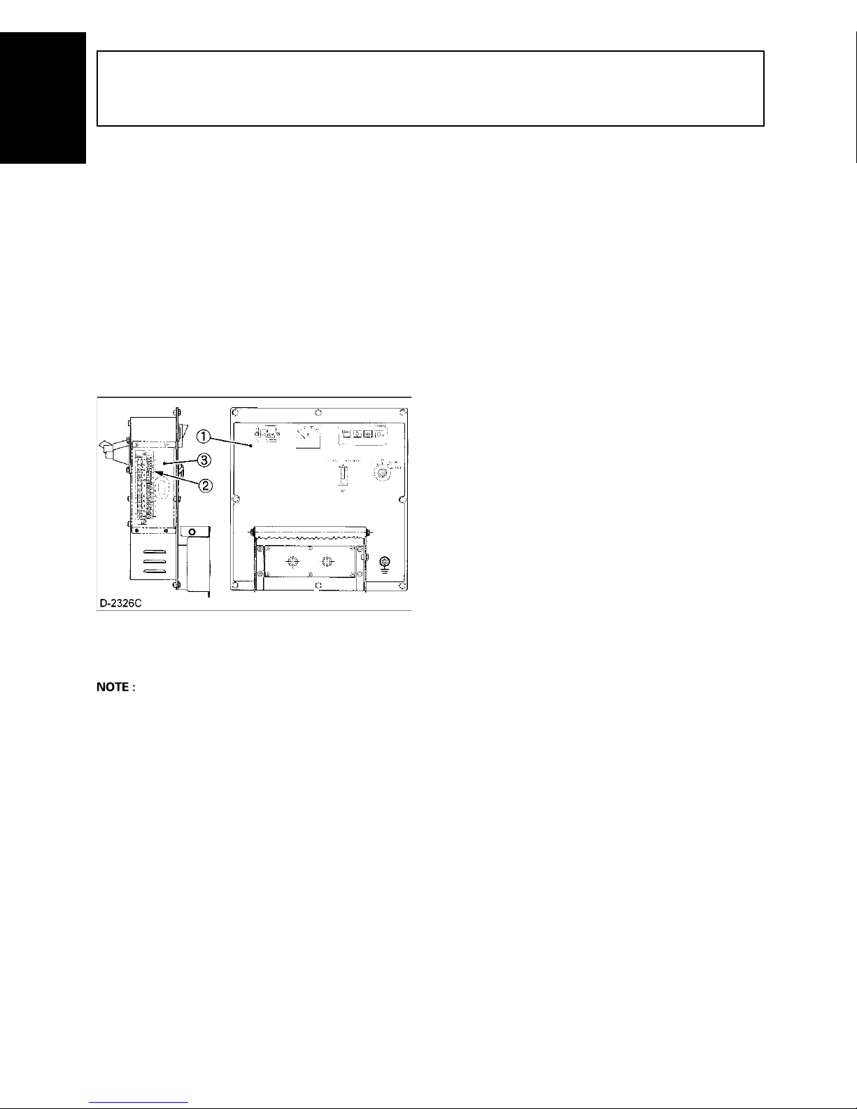
50 AUTOMATIC START/STOP UNIT (A S/S UNIT)
AUTOMATIC START/STOP UNIT (A S/S UNIT)
ENGLISH
To connect the machine to the A S/S UNIT the generator
is equipped with the ECTT on the left side panel of the
control panel.
To connect the exterior apparatus with the machine,
perform the following instructions;
1. Remove the terminal taps cover.
2. Connect the unit to the ECTT with the wiring
harnesses, following the operator’s manual of the A
S/S unit.
3. To assemble the TTC, set the TTC, reversing the up/
down sides of the cover.
For nomenclature and connection of terminal taps are
referred to the “WIRING DIAGRAM” section . (See page
51.)
(1) Control panel
(2) Exterior connection terminal taps (ECTT)
(3) Terminal taps cover (TTC)
A For D1005, V1305 engine type the exterior connection
terminal taps are placed on the right side of control
panel.
Page 67

WIRING DIAGRAM 51
ENGLISH
WIRING DIAGRAM
Page 68

WIRING DIAGRAM52
ENGLISH
Page 69

WIRING DIAGRAM 53
ENGLISH
Page 70

WIRING DIAGRAM54
ENGLISH
Page 71

WIRING DIAGRAM 55
ENGLISH
Page 72

WIRING DIAGRAM56
ENGLISH
Page 73
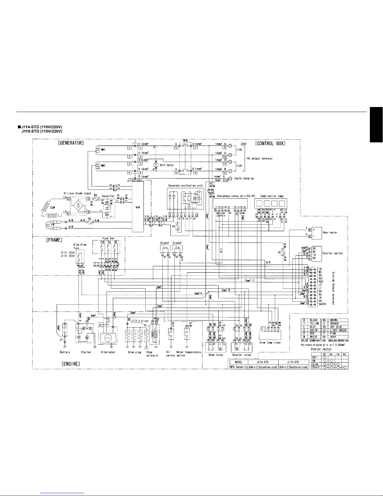
WIRING DIAGRAM 57
ENGLISH
Page 74

WIRING DIAGRAM58
ENGLISH
Page 75

WIRING DIAGRAM 59
ENGLISH
Page 76

WIRING DIAGRAM60
ENGLISH
Page 77

WIRING DIAGRAM 61
ENGLISH
Page 78

WIRING DIAGRAM62
ENGLISH
Page 79

WIRING DIAGRAM 63
ENGLISH
Page 80

WIRING DIAGRAM64
ENGLISH
Page 81

WIRING DIAGRAM 65
ENGLISH
Page 82

WIRING DIAGRAM66
ENGLISH
Page 83

WIRING DIAGRAM 67
ENGLISH
Page 84

WIRING DIAGRAM68
ENGLISH
Page 85

WIRING DIAGRAM 69
ENGLISH
 Loading...