

Kubota Impac 500 Owner's Manual

IMPAC 500
IMPAC™ for Kubota™
SAFETY, INSTALLATION, OPERATION &
MAINTENANCE
OWNER’S MANUAL
MODEL Impac 500

TABLE OF CONTENT
INTRODUCTION ................................................................................... 1
PRODUCT IDENTIFICATION ............................................................. 1
SAFETY .................................................................................................
SAFETY LABELS ...........................................................................
OPERATIONAL SAFETY................................................................ 4 - 6
INSTALLATION INSTRUCTIONS ................................................. 7 - 14
IMPAC 500 OPERATING CONTROLS .......................................... 15
OPERATING THE IMPAC 500 SYSTEM........................................ 16 - 17
IMPAC 500 INSPECTION AND MAINTENANCE........................... 18 - 21
ELECTRICAL WIRING DIAGRAM ................................................. 22
QUALITY SERVICE / CONTACT INFORMATION ......................... 23
CONTACT INFORMATION ............................................................ 23
WARRANTY .................................................................................... 23
SPECIFICATIONS .......................................................................... 24
2
2 - 3
Notes ................................................................................................ 25
INTRODUCTION PRODUCT IDENTIFICATION
Using your Operator’s Manual
Read this entir
Safety Information, before operating.
This Manual is an important part of your machine.
Keep all Manuals in a convenient location so they
can be accessed easily.
Use the Safety and Operating information in both the
IMPAC 500™ Operator’s Manual and the Machine
Operator’s Manual to operate and service the unit
safely and correctly.
The Assembly and Installation sections of this
Manual provide information to assemble and install
the IMPAC 500™ system into the cargo box
vehicle.
Refer to the Service s
required.
e Operator’s Manual, especially the
ection if any adjustments are
of your
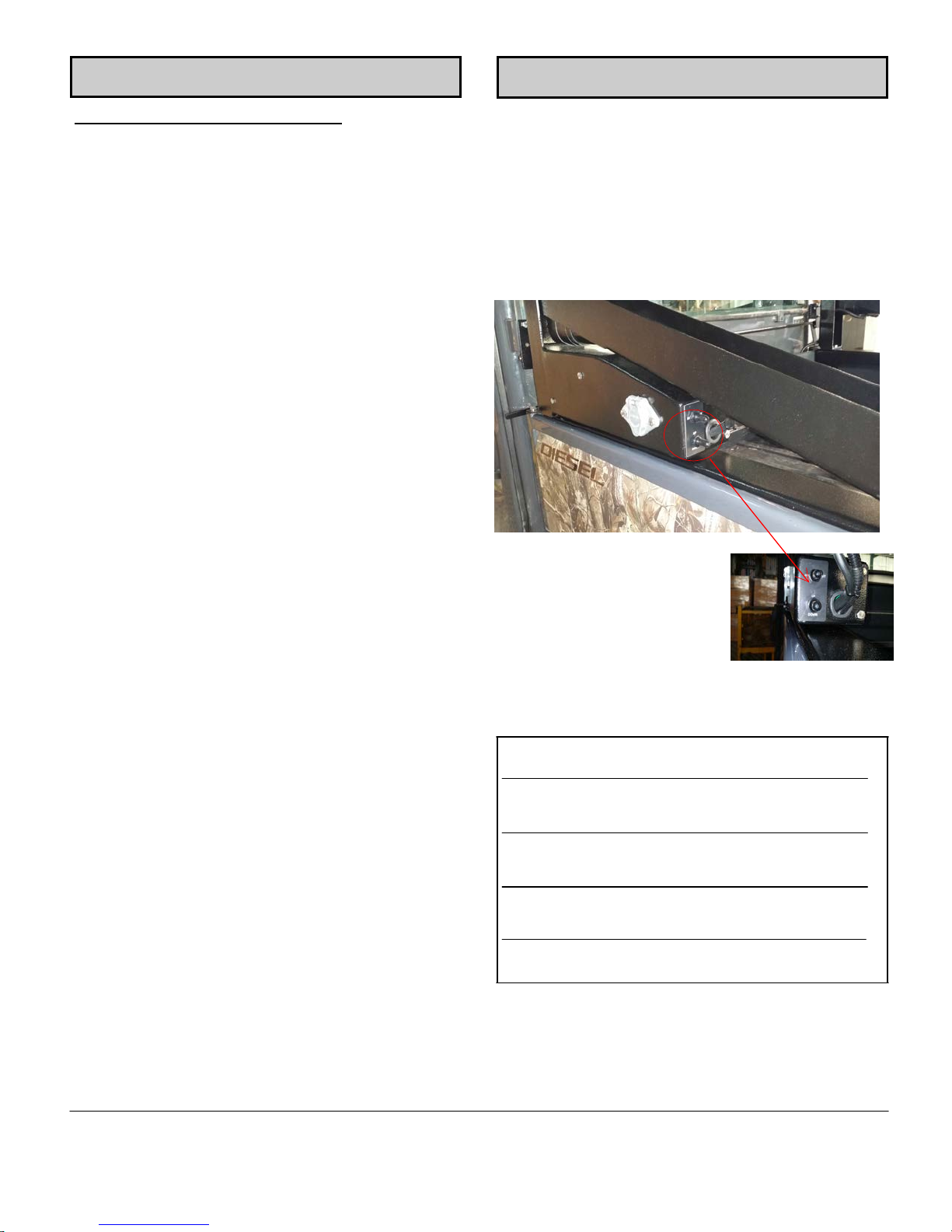
When contacting the IMPAC 500™ Customer
Contact Center for information on servicing,
always provide the Product Serial Number (located
on the control box) and Date of Purchase.
Locate the Product Serial
Number and record all relevant
information in the spaces
below.
If you have any questions or concerns with the
assembly, installation or operation of the unit,
contact your IMPAC 500™ System Representative
or
IMPAC™ CUSTOMER CONTACT CENTER:
1-956-233-3294
DATE OF PURCHASE:
DEALER NAME:
DEALER PHONE:
PRODUCT SERIAL NUMBER:
Page 1
CAUTION
SAFETY
READ THIS ENTIRE OPERATOR’S MANUAL BEFORE BEGINNING WORK
ALWAYS WEAR SAFETY GLASSES AND USE CARE WHEN WORKING WITH POWER TOOLS
Safety is a primary concern in the design and manufacturing of IMPAC™ products. Unfortunately, all efforts to
provide safe equipment can be totally negated by a single careless act by an Installer or Operator.
Accident Prevention and Safety are dependent upon the awareness and proper training of the personnel who
operate and maintain this equipment. The best safety device is a careful and informed Owner/Operator.
Taking precedence over any specific rule, however, is the most important rule of all: SAFETY FIRST
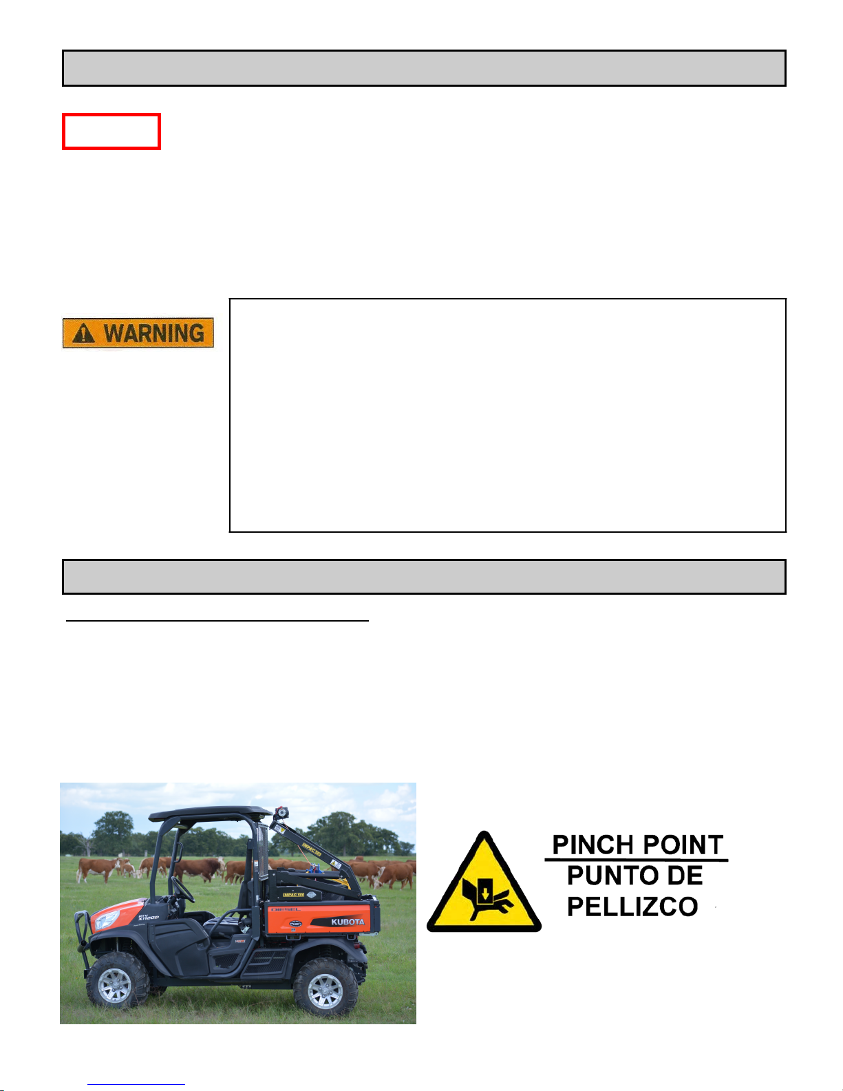
IMPAC™ Model P500™ lift system has a rated lift capacity of 227 kg (500 lbs)
Maximum Load capacity at full extension – 227 kg (500 lbs)
Maximum Winch load capacity at full extension – 227 kg (500 lbs)
Maximum Vehicle operating angle – 5 degrees
OVERLOADI
Read and obey all Safety Symbols, Warnings, Cautionary Notes and Operating
Instructions on the IMPAC 500™ and in this Manual.
Ensure that all placards are in place and legible.
Failure to comply with safety precautions in this Manual and on the IMPAC 500™
is a safety violation that may result in serious injury, death or property damage.
NG YOUR VEHICLE CAN CAUSE POTENTIAL SAFETY HAZARDS!
SAFETY LABELS
Understanding Machine Safety Labels
The unit’s Safety Labels, as shown in this section, are placed in important areas on your IMPAC 500™ unit to
draw attention to potential safety hazards.
The Safety Labels on your unit are pictorial, ensuring they are most easily and universally understood.
Where necessary, the Operator’s Manual explains any potential safety hazards in special safety messages
identified with the words CAUTION or BE CAREFUL, and incorporate the Safety-Alert symbols shown below.
Page 2
SAFETY LABELS (cont…)
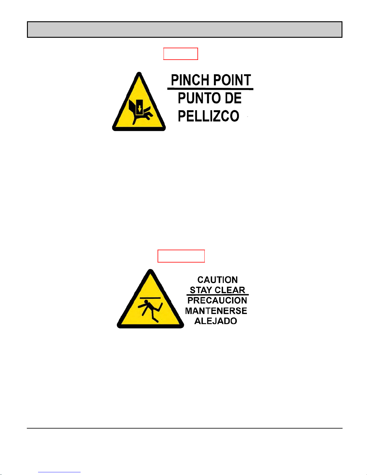
CAUTION
CAUTION - KEEP HANDS AWAY
This label is positioned on the lifting arms near the
“pinch points” where the lift arms, unit frame and
linkages converge, as well as on the lift arm
hydraulic cylinders where they pass into and out of
the lift frame.
To avoid risk of serious injury it is essential to keep
hands away from this area while the unit is in use.
It is the responsibility of the Operator to advise
others, including bystanders of this risk.
NEVER remove the CAUTION label and replace
immediately if missing.
BE CAREFUL
BE CAREFUL
NEVER depend
lifted load.
NEVER stand or move under a lifted load.
While operating the winch use the holding strap to
maneuver the load.
DO NOT grip the rope or the rope hook.
It is recommended that leather gloves are used
when rewinding the rope after use.
on the hoist or rope to support a
Page 3

OPERATIONAL SAFETY
It is the Owner’s/Operator’s responsibility to use good judgment in the operation and maintenance of the
IMPAC™ Load Lift System.
PLEASE READ THIS ENTIRE OPERATOR’S MANUAL BEFORE BEGINNING WORK
It is the Owner’s/Operator’s responsibility to instruct and ensure that all Operators fully understand the safe
operation and maintenance of the IMPAC™ System. Anyone who operates the equipment must read and fully
understand this Manual prior to operating the lift system. Failure to observe these instructions and safety
procedures can result in serious injury and/or property damage.
Train IMPAC 500™ inspection and maintenance personnel for routine and periodic inspections and
maintenance. Such training requirements should also provide information for compliance with any Federal,
State and Local Code Requirements, existing Company safety rules and regulations and instructions
furnished for the IMPAC 500™ system. Because IMPAC 500™ has no direct involvement or control
over the operation and application of the IMPAC 500™ System once it is installed on a vehicle,
conforming to good safety practices is the responsibility of the Owner, the User, and its operating personnel.
Therefore, it is essential that all personnel who will install, inspect, test, maintain and operate the IMPAC
500™ unit, read and completely understand the contents of this Owner’s
Manual. Only those authorized and qualified personnel who have shown that they have read and
understood the Owner’s Manual and have understood the proper operation and maintenance of the IMPAC
500™ System should be permitted to operate the IMPAC 500™ System.
General Safety Information
READ and save all instructions.
NEVER engage in any practice that will divert your attention while operating the IMPAC 500™ System.
operate the IMPAC 500™ System from the Driver or Passenger seats.
ALWAYS disconnect the IMPAC 500™ Controller and cable from the receptacle when moving the vehicle.
NEVER overload. Overloads can cause damage and create unsafe operating conditions. Ensure that the rated
load capacity of any sling, lifter or fitting is not exceeded. Learn to use the IMPAC 500™ System correctly.
Take time to practice so that you are comfortable with the operating system.
NEVER
Maximum Load capacity at full extension – 227 kg (500lbs)
Maximum Winch load capacity at full extension – 227 kg (500 lbs)
Maximum vehicle operating angle – 5 degrees
NEVER handle the Hoist rope with bare hands
ALWAYS use leather gloves when handling the rope.
NEVER allow children or unauthorized personnel to operate the IMPAC 500™ System at any time.
use the unit for lifting, supporting or transporting people.
NEVER stand beneath the load or IMPAC 500™ System lift frame or use over areas where people are present
NEVER operate the IMPAC 500™ System with Driver or Passenger in the vehicle.
NEVER
Page 4

OPERATIONAL SAFETY
OPERATIONAL SAFETY (cont…)
General Safety Information (cont…)
(cont…)
NEVER operate the IMPAC 500™ System when someone is within an unsafe distance (clear of moving
components).
NEVER lift a load with a weight exceeding 227 kg (500lb).
Maximum Load cap
Maximum Winch load capacity at full extension – 227 kg (500 lbs)
NEVER lift anything with the IMPAC 500™ System while the Kubota™ is on an incline or side of hill.
Maximum v
NEVER lift anything into the bed that will not fit, cause the vehicle to be unstable when driven or that cannot be
safely secured as to not move around when transported.
USE CAUTION - keep people, pets and property clear of the path of the load - keep work area clear and free of
obstructions.
DO NOT use for supporting an unattended load.
DO NOT use for towing other vehicles.
ALWAYS install cargo bed locking pins before operating the IMPAC 500™ System.
ehicle operating angle – 5 degrees
acity at full extension – 227 kg (500lbs)
Before Operating
Visually inspect the hook, synthetic rope, hoist and accessories for any damage or wear.
Reject nylon slings with abnormal wear, torn stitching, broken or cut fibers or discoloration or deterioration.
Reject synthe
attachments.
Ensure that the Kubota™ cargo bed and suspension system are in good condition; i.e. shocks, springs
etc.
Check to see tha
Check to ensu
tic rope with kinking, crushing, evidence of heat damage, cracks, deformation or worn end
t all fasteners are secure and that the gusset screws are all tight.
re that the Cargo Bed/Box is locked to the main frame with provided locking device.
NEVER MOVE Kubota™ WITH A SUSPENDED LOAD
Page 5

OPERATIONAL SAFETY (cont…)
Moving a Load
Center the hook over the load to keep the synthetic rope from slipping out of the drum grooves and
overlapping, and to prevent the load from swinging when it is lifted. Inspect the drum to verify that the
synthetic rope is in the grooves. Lift the load only high enough to clear the tailgate or rear of the cargo bed.
Keep fingers a
NEVER stand in cargo bed when loading or unloading.
NEVER operate IMPAC 500™ System while the Kubota™ is on an incline or side of a hill.
AVOID SIDE P
the rope or destabilizing the winch.
NEVER leave suspended loads unattended. In an emergency where the IMPAC 500™ System has become
inoperative, or if a load must be left suspended for any length of time, barricade and post signs under the load
and on all three sides. Turn off the Kubota™ and lock it so it cannot be moved.
nd arms well clear of the pinch points between the IMPAC 500™ System arms and frames.
ULLS - These can cause the winch synthetic rope to slip out of the drum groove, damaging
Disclaimer
The IMPAC 500™ System is manufactured to exacting specifications and standards using high quality
materials, components and workmanship.
Guidelines for load lifting and safe operation need to be observed when using/operating the IMPAC 500™
load lift system. Overall performance of the system depends on the guidelines and safe operation
information in the OM being observed in conjunction with conditions on the day.
Examples of "conditions on the day" could be temperature variations, including highs and lows; hot, dry, cold,
raining; as well as size and type of load being lifted.
IMPAC 500™ and/or Kubota are not able to control your working environment or safe operating practices
at any given time, and are therefore not liable for variations in performance or injury resulting from misuse
or variations in "conditions on the day".
Page 6
INSTALLATION INSTRUCTIONS (cont…)
BEFORE INSTALLING LIFT SYSTEM -
PARK THE Polaris Ranger™ ON FLAT LEVEL GROUND, SET
PARK BRAKE AND CHOCK THE WHEELS
After the Polaris Ranger™ is securely parked, clear the
Polaris Ranger™ bed of any objects and ensure that it is
clean.
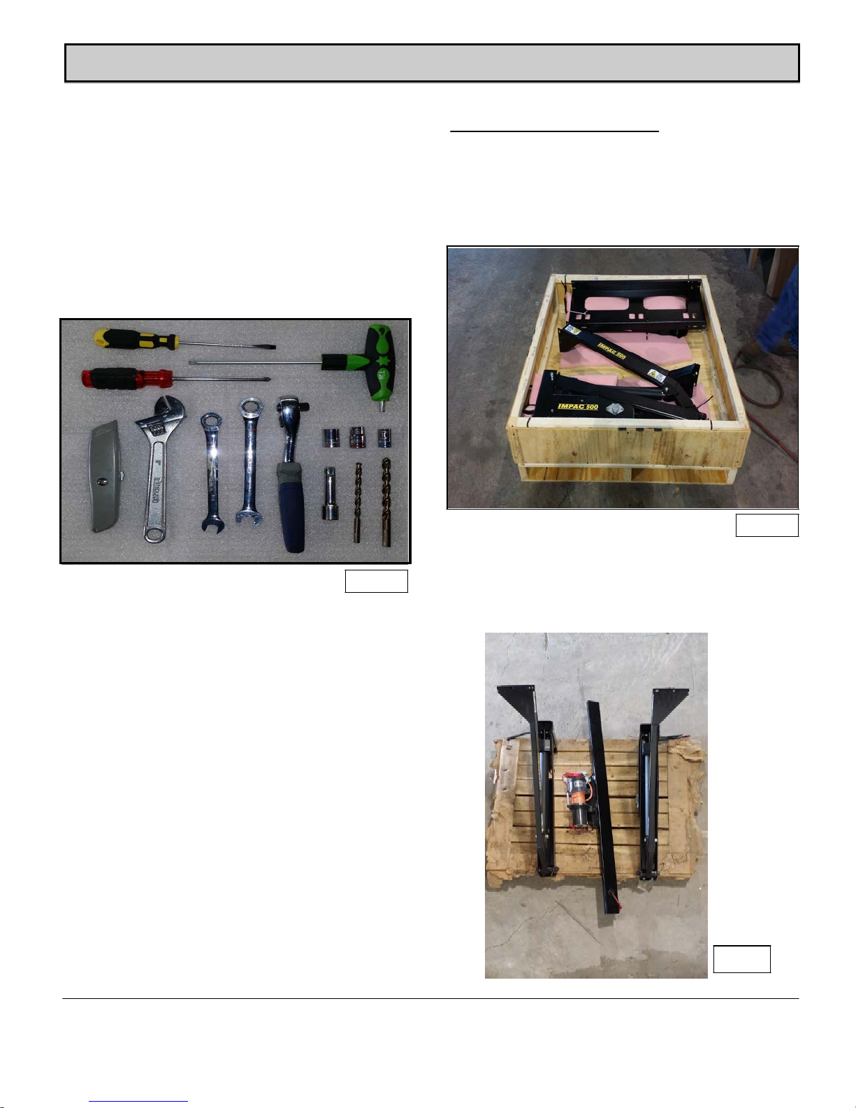
Before taking the next s
(See Figure 1)
teps - lay out the following tools.
INSTALLING LIFT SYSTEM
Your Polaris Ranger™ IMPAC 500™ System is shipped in
a box on a pallet. Using a crane, forklift or similar, place
the box/pallet on flat level ground, positioning it behind
and in line with the Polaris Ranger™ . This will make the
installation easier.(See Figure 2)
Tools needed for installation
1) Flat Head Screwdriver
2) Phillips Screwdriver
3) Utility Knife
4) Crescent Adjustable Wrench
5) 7/16 inch Open End Wrench
6) 1/2 inch Open End Wrench
7)
8)
9)
10)
11)
12)
13)
14)
15)
16)
17)
9/16 inch Open End Wrench
Ratchet
Ratchet Extension
10mm Socket
7/16 inch Socket
1/2" inch Socket
9/16" inch Socket
T30 Torx Wrench
17/64 inch Drill Bit
5/16 inch Drill Bit
Drill
Figure 1
Figure 2
Remove the top
Remove the hardware package.
Remove the hardware that is securing the Lift System to
the base of the box/pallet. (See Figure 3)
of the box.
Figure 3
Page 7
 Loading...