

Kubota GZD21-2 HD, GZD15-3 HD, GZD15-3 LD Assembly Manual
ASSEMBLY
INSTRUCTIONS
INSTRUCTIONS DE
ENGLISH
MONTAGE
MONTAGEANLEITUNG
MODELS
GZD15-3 LD/HD
MODELES
GZD21-2 HD
MODELLE
FRANÇAISDEUTSCH
1BDABANAP2170
PRINTED IN JAPAN
KUBOTA Corporation 2014
IMPRIME AU JAPON
DRUCK : JAPAN
©
Code No.
o
AT . B . 2 - 3 . 2 . AK N
Code Nr.
de code. K2013-7152-2

TO THE DEALER
This manual contains procedures intended to assist the dealer in unpacking and
assembling the product before delivering to the customer.
The customer's purchase is based on condence in both the product and your
store. Observe the procedures in this manual to assemble and adjust equipment for
your customer's safety and satisfaction. When fully assembled, check function of
each part and feature.
3
The following safety alert symbol marks and indication are found throughout this
manual in steps where particular attention is required so as to ensure your safety
and to avoid product damage. Observe the instructions in these warnings where
indicated.
3
3
3
IMPORTANT : Indicates that equipment or property damage could result if
NOTE : Gives helpful information.
DANGER : Indicates an imminently hazardous situation which, if not
WARNING : Indicates a potentially hazardous situation which, if not
CAUTION : Indicates a potentially hazardous situation which, if not
avoided, will result in death or serious injury.
avoided, could result in death or serious injury.
avoided, could result in minor or moderate injury.
instructions are not followed.
SAFETY FIRST

AU REVENDEUR
Ce manuel contient les procédures prévues pour aider le revendeur monter le
produit avant la livraison au client.
L'achat du client est basé sur la conance qu'il accorde au produit et à votre
magasin. Respecter la procédure décrite dans ce manuel et régler l'équipement
pour la sécurité de votre client. Lorsque le montage est terminé, vérier le bon
fonctionnement de chaque pièce et caractéristique.
Pour vos clients qui parlent français, joindre l'étiquette en français qui se trouve
dans l'emballage des accessoires.
3
Le symbole et les indications de sécurité suivants se trouvent dans ce manuel
lorsqu'une attention particulière est requise pour assurer la sécurité en cours
d'utilisation et éviter d'endommager le produit. Respecter les instructions données
dans ces avertissements.
3
3
3
IMPORTANT : Si les instructions se sont pas suivies, l'équipement ou
LA SECURITE EN PREMIER LIEU
DANGER : Indique une situation éminemment dangereuse. Des
AVERTISSEMENT : Indique une situation potentiellement dangereuse. Des
ATTENTION : Indique une situation potentiellement dangereuse. Des
blessures graves ou la mort peuvent survenir si cette
situation n'est pas évitée.
blessures graves ou la mort peuvent survenir si cette
situation n'est pas évitée.
blessures mineures ou graves peuvent survenir si cette
situation n'est pas évitée.
vos biens peuvent être endommagés.
NOTE : Donne des informations pertinentes.

AN DEN HÄNDLER
Diese Anleitung beinhaltet Verfahrensschritte, die dem Händler beim Zusammenbau
des Produkts helfen sollen, bevor es an den Kunden ausgeliefert wird.
Der Kauf durch den Kunden basiert auf dem Vertrauen des Kunden am Gerät und
Ihrem Geschäft. Beachten Sie bitte die Verfahrensschritte in dieser Anleitung um
den Zusammenbau und die Einstellung am Gerät zur vollsten Zufriedenheit des
Kunden durchzuführen. Nach dem Zusammenbau ist das Gerät auf sämtliche
Funktionen zu überprüfen.
3
Das folgende Sicherheits-Warnsymbol ist vom Anfang bis zum Ende in dieser
Bedienungsanleitung an den Stellen zu nden, wo spezielle Vorsicht geboten
ist, die die Sicherheit des Bedieners sowie die Sicherheit der sich in der Nähe
bendlichen Personen betrifft, und um Schaden am Gerät zu vermeiden. Befolgen
Sie deshalb diese Warnhinweise in den bezeichneten Abschnitten.
3
3
3
WICHTIG : Diese Überschrift macht Sie darauf aufmerksam, die
SICHERHEIT KOMMT ZUERST
GEFAHR : Dieses Zeichen weist auf die Möglichkeit einer äußerst
gefährlichen Situation hin, die zu einem schweren Unfall
führen kann, wenn sie nicht vermieden wird.
WARNUNG : Dieses Zeichen warnt davor, keine gefährlichen Situationen
einzugehen, die zu schweren Unfällen führen können.
VORSICHT : Dieses Zeichen macht Sie darauf aufmerksam, dass es
durch unaufmerksames Verhalten zu Unfällen kommen kann.
entsprechenden Hinweise der Anleitung zu beachten, damit
es nicht zu Beschädigungen von Mäher und Anbaugeräten
kommen kann.
HINWEIS : Unter dieser Überschrift nden Sie wichtige Informationen.
1
ENGLISH
SAFETY
To prevent accidents, read through the following items
before starting work, and always regard safety when
working. It is your responsibility to ensure your safety on
the job.
1. Preparations
(1) Select a work site which is level, sufficiently
spacious and not in the vicinity of dangerous
objects.
(2) Avoid poorly ventilated rooms. Asphyxiation from
exhaust fumes is always a possibility that
accompanies running engine.
(3) Working clothes which may be pinched or caught
in the equipment must not be worn. Loose
clothing can cause serious injury or death.
(4) Always wear a mask and protective goggles
during work when dust or flying debris is thrown
about.
2. Assembly and adjustments
(1) Before assembling equipment, read the assembly
instructions for the product to become familiar
with the equipment and procedures.
(2) Use only adequate and required equipment, tools
and instruments (torque wrench or battery
hydrometer).
(3) Set the parking brake and place blocks in front of
wheels (when they're contacting the ground) to
prevent machine movement.
(4) Lower the attachment or implement to the ground
before assembling or adjusting equipment.
(5) Before working under suspended or raised
equipment, support the equipment or attachment
to prevent the machine from falling or moving out
of place.
(6) Keep fire from cigarettes, matches or other
ignition sources away from fuel, oil, antifreeze and
other flammable materials.
3. After assembly check
(1) Once the equipment is fully assembled, select a
safe place for a test run. Prevent onlookers from
approaching the equipment.
To avoid serious injury or death:
A Do not start engine or operate levers from
anywhere other than the seat.
To avoid serious injury or death:
A Do not bypass-start the equipment. Short
circuiting the starter terminal runs the risk that
the equipment will start operating or moving
unexpectedly.
2
ENGLISH
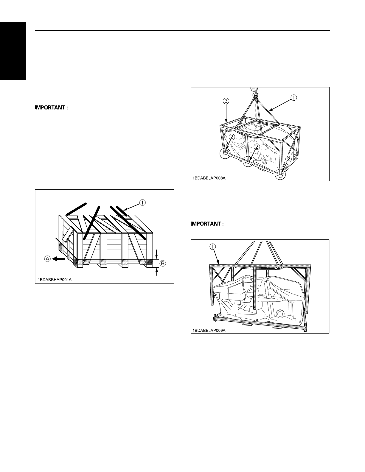
UNPACKING AND CHECKING PARTS
BUNPACKING WOODEN CRATE
1. Hook a hoist to the 4 corners of the crate and raise the
hoist cable until taut.
This serves to prevent the upper part of the crate from
striking the machine when cut.
2. Saw the crate as indicated in the figure below.
A Sawing outside the indicated area may damage the
machine or accessory parts.
A Be sure that the crate is free of other obstructions (e.g.
nails, staples and etc.).
3. Raise the upper part of crate and remove from the
immediate area.
4. Remove the remaining slats from the crate.
These are indicated by the oblique lines in Figure 1.
BUNPACKING IRON CRATE
1. Hook nylon ropes at the four corners of the iron-crate's
top stay. Pull up the nylon ropes until they get just tight.
2. Remove the six bolts from behind the vertical supports
on both sides of the iron crate.
3. Lift and detach the top frame of the iron crate.
A In lifting the top frame, be careful to keep the crate's
vertical supports from scratching the machine.
Figure 1: Cutting area of the crate
(1) Nylon band (A) Front
(B) 300 mm
(1) Nylon band
(2) 6-Bolt
(3) Iron crate
(1) Iron crate
3
ENGLISH
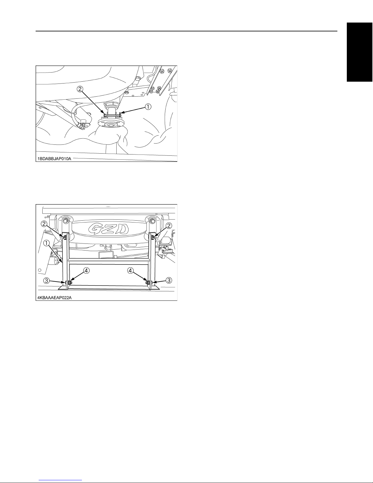
4. Unlocking both ends of the rear axle
Remove the snap pins off both ends of the rear axle,
and draw out the headed pins.
5. Remove the fixtures (1), (2), (3), (4) from the machine
front as shown in the figure below.
Join the fixtures (1), (3), (4) to the iron crate bottom.
(1) Snap pin
(2) Headed pin
(1) Stay
(2) Nut
(3) Bolt
(4) Nut
4
ENGLISH
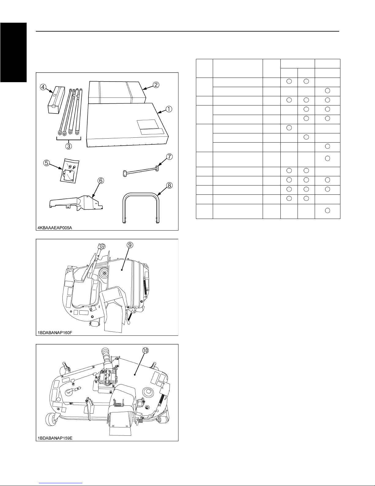
BTHE ACCESSORIES PACKAGED
TOGETHER WITH GZD15-3 AND GZD21-2
REF.
No.
PART NAME Q'TY
GZD15-3 GZD21-2
LD HD HD
(1)
400BAG, ASSY 1 ---
500BAG, ASSY 1 --- ---
(2) 400COVER, ASSY 1
(3)
ARM (LIFT, UPPER) 2 ---
ARM (LIFT, LOWER) 2 ---
(4)
PART, SHIPPED, KIT 1 --- ---
PART, SHIPPED, KIT 1 --- ---
PART, SHIPPED, KIT 1 --- ---
(5)
ACCESSORIES,
ASSY (Bag)
1 --- ---
(6) COVER (LH) 1 ---
(7) PIPE (ROPS) 1
(8) PIPE (ROPS UPPER) 1
(9) RC42GZD-3, MOWER 1 ---
(10)
RCK48GZD-2,
MOWER
1 --- ---
5
ENGLISH
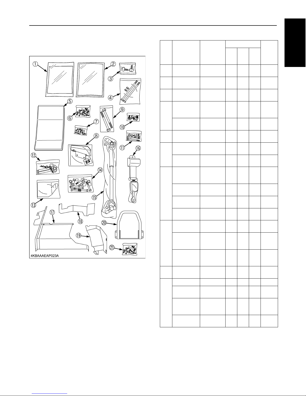
BACCESSORIES ASSY
<Box>
REF.
NO.
PART No. PART NAME
QUANTITY
RE-
MARKS
GZD
15-3
LD
GZD
15-3
HD
GZD
21-2
HD
(1) K2013-7122-0
MANUAL,
OP
111
(2) K2013-7152-2
MANUAL,
INST
111
(3) PL501-6892-0
KEY,
STARTER
111
(4)
K2011-1813-0
BOLT,
HEX (M12 x
1.25 x 210)
222
M12 x
210
02572-50120
NUT,
LOCKING
222M12
(5) K2011-6550-4
SET LABEL,
MAINTE.
111
(6)
01133-51225
BOLT,
SEMS
888
M12 x
25
01123-50825
BOLT,
SEMS
111M8 x 25
(7)
K2013-2141-0
BOLT,
FLANGE
(M8 E 26)
4 4 --- M8 x 26
01754-50816
BOLT,
FLANGE
4 4 --- M8 x 16
K3655-5221-0
WASHER
(BOLT)
4 4 ---
04613-50050
CIR-CLIP,
EXTERNAL
6 6 ---
(8)
K2013-2138-0
PLATE
(LH 2)
1 1 ---
K2013-2142-0
PLATE
(BOLT
HOLDER 16)
4 4 ---
K2013-2143-0
BOLT,
FLANGE
(M8 E 35)
2 2 --- M8 x 35
(9) K2031-8616-0
BOLT
(M16 x 2)
222
M16 x
147
(10)
K3611-8256-0 NUT 2 2 2 M16
01133-51020
BOLT,
SEMS
111
M10 x
20
04512-50100
WASHER,
SPRING
LOCK
333
02572-50100
NUT,
LOCKING
333M10
6
ENGLISH
<Bag>
REF.
NO.
PART No. PART NAME
QUANTITY
RE-
MARKS
GZD
15-3
LD
GZD
15-3
HD
GZD
21-2
HD
(11)
01133-51000
BOLT,
SEMS
222
M10 x
100
04512-50100
WASHER,
SPRING
LOCK
222
02118-50100 HEX. NUT 2 2 2 M10
01615-51025
BOLT,
CUP-SQ-NK
222
M10 x
25
(12) K2031-8615-0
PIN (LOCK),
SET
222
(13) K2013-5681-2
SUPPORT
(SEAT
BELT)
111
(14)
K6082-6353-0
COLLAR,
ARM
--- 8 8
01173-51470 HEX. BOLT --- 7 7
M14 x
70
02574-50140
NUT,
LOCKING
--- 7 7 M14
04011-50140
WASHER,
PLAIN
--- 11 11
(15) K5243-3203-0
ASSY
JOINT,
UNIVERSAL
11---
(16) K2771-5685-2
BELT,
SEAT, ASSY
111
(17) K5245-7271-3
COVER
(CENTER)
11---
(18) K5245-7269-2
COVER
(CENTER
LH)
11---
(19) K2013-2134-0
COVER
(U/J)
11---
(20) K2031-5351-4
GUARD
(FRONT)
111
(21) 01138-51430
BOLT,
SEMS
888
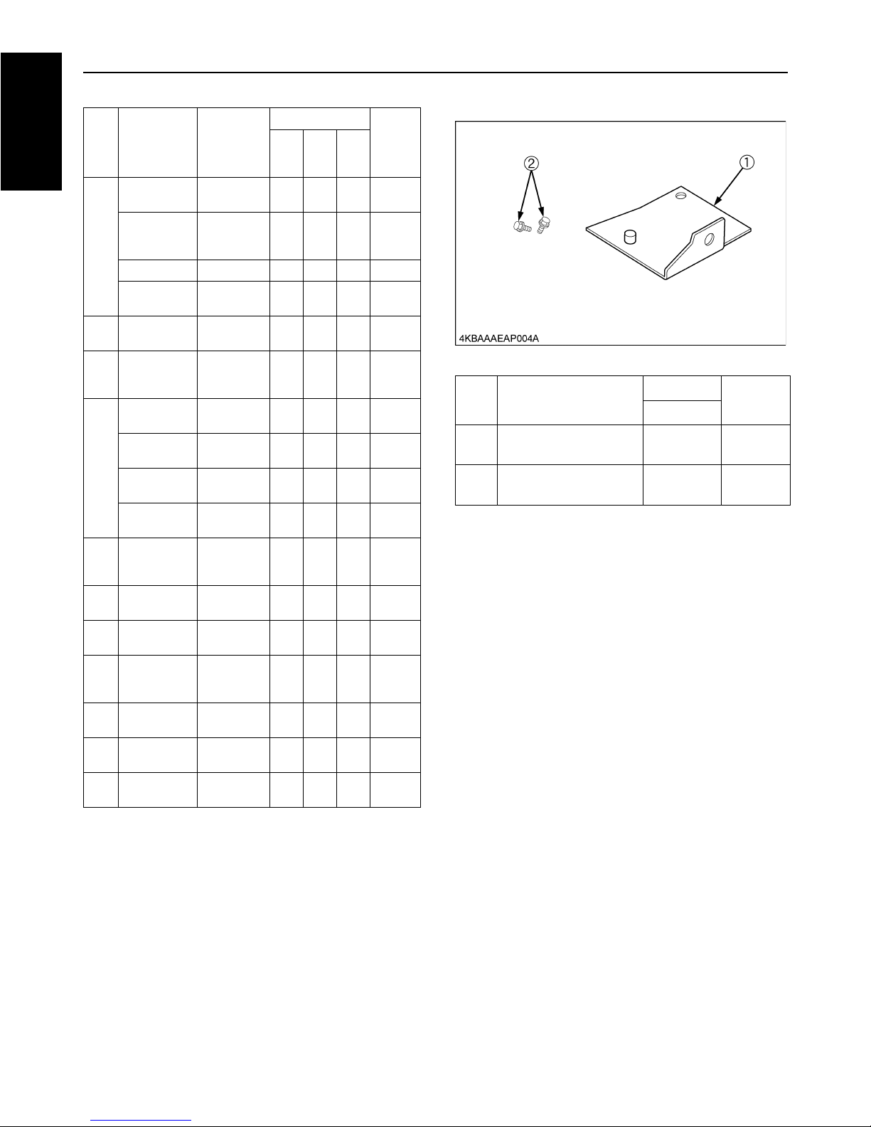
REF.
No.
PART NAME
QUANTITY
RE-
MARKS
GZD21-2
(1)
UNIVERSAL JOINT
COVER FRONT STAY
1
(2)
BOLT (for Universal
joint cover front stay)
2 M8 x 16
7
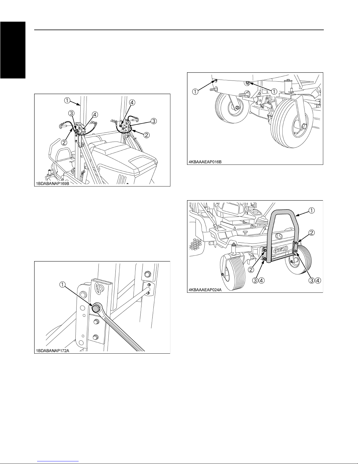
ENGLISH
ASSEMBLY OF THE GRASS CATCHER
CONTAINER
<High Dump>
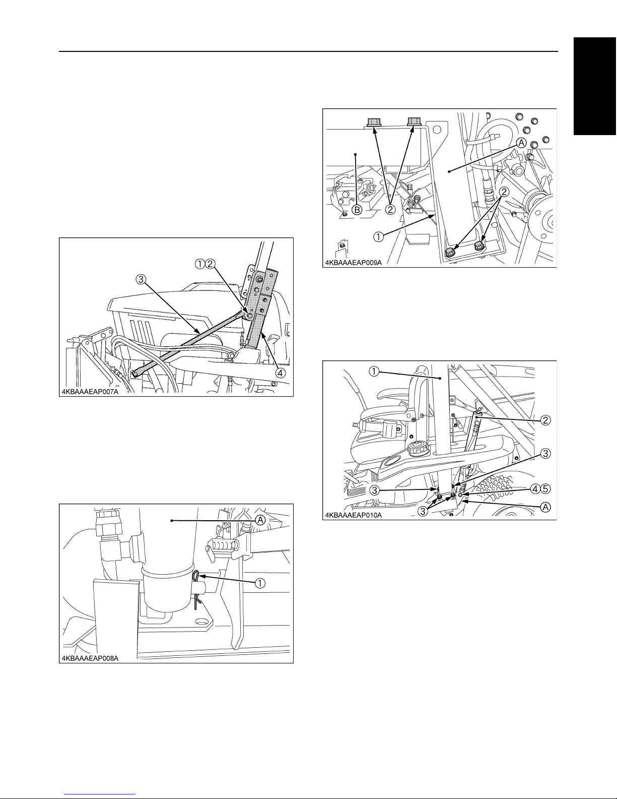
BPreparations for Assembling the Under
ROPS Pipe
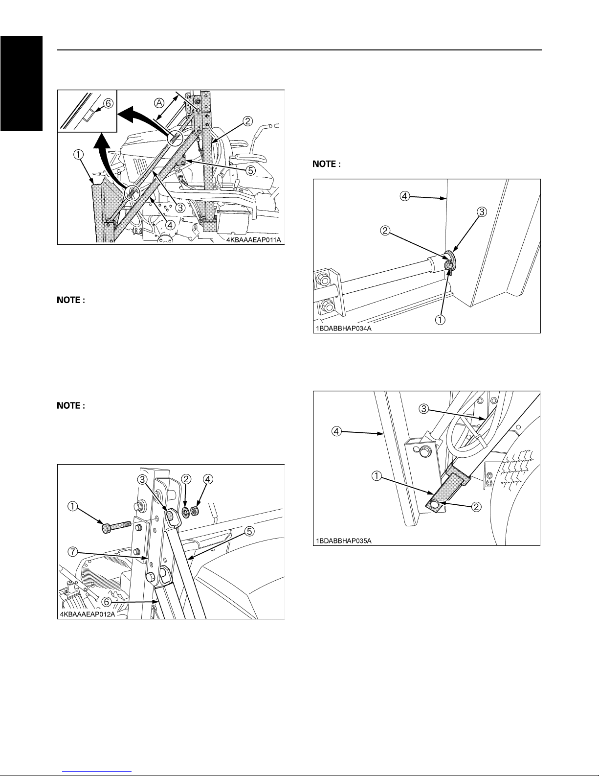
1. Make a team of two to do this job.
2. Remove the bolt (1) and nut (2) from the lift rod (for
both sides).
The bolt (1) will be used again to reassemble this
component. Be careful not to lose them. (The nut (2)
will not be reused.)
BInstalling the Under ROPS Pipe
1. Remove the snap pin (1) that keeps the cylinder (A) in
place.
2. Remove the 4 bolts (2) first and then the fixing plate
(1). (The same for both sides)
4 bolts (2) will not be reused.
3. Using the bolts (3), temporarily connect the pipes
(ROPS, UNDER) (1) to the frame (3). (4 bolts each for
each side)
Fix the cylinder (2) to the frame (A) with the headed pin
(4) and snap pin (5).
(1) Bolt
(2) Nut
(3) Lift rod
(4) Under ROPS pipe
(1) Snap pin (A) Cylinder
(1) Fixing plate
(2) Bolt
(A) PIPE, ROPS UNDER
(B) Frame
(1) PIPE, ROPS UNDER
(2) Cylinder
(3) Bolt (M14 x 30)
(4) Headed pin
(5) Snap pin
(A) Frame
8
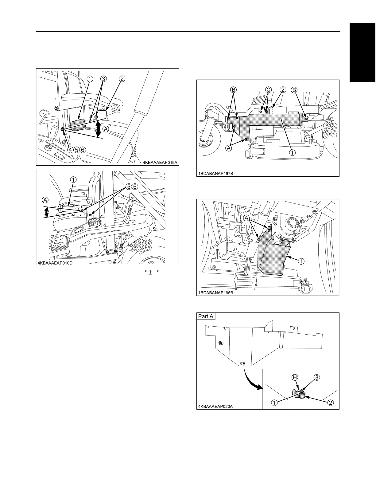
ENGLISH
BInstalling the Lift Arms (Upper and Lower)
A There are two upper lift arms. The lift arm that has a
stay is for the right side. Be careful not to confuse the
right and left ones and to keep the stay outward.
C Under ROPS pipe side
Using bolts, washers, collars and nuts, install the upper lift
arm and the lower lift arm to PIPE, ROPS UNDER.
Tightening torque: 40 to 50 N-m (4.1 to 5.1 kgf-m)
A Set the washer on the nut side. Insert the bolt from the
outside. For the lower lift arm, set the cylinder
mounting bracket downward
A Apply grease between the lift arm and PIPE, ROPS
UNDER.
C Bag base side
(Right side lower lift arm)
1. Remove the headed pins and take off the arm cam
from the bag base.
2. At the right side, using the arm cam, collars and
washers, install the lower lift arm.
3. Fix the arm cam with the headed pin and the snap pin.
A Set the washers on the inside of the bag base only.
(1) Bag base
(2) PIPE, ROPS UNDER
(3) Upper lift arm
(4) Lower lift arm
(5) Cylinder mounting bracket
(6) Stay
(1) Bolt (M14 x 70)
(2) Washer
(3) Collar
(4) Nut (M14)
(5) Upper lift arm
(6) Lower lift arm
(7) PIPE, ROPS UNDER
(1) Headed pin
(2) Snap pin
(3) Washer
(4) Bag base
(1) Arm cam
(2) Collar
(3) Lower lift arm
(4) Bag base
9
ENGLISH
(Left side lower lift arm)
Using bolts, washers, collars and nuts, install the lower lift
arm to the bag base.
Tightening torque: 40 to 50 N-m (4.1 to 5.1 kgf-m)
A Set the washers on both sides. Insert the bolt from the
outside.
A Apply grease between the lift arm and the bag base.
(Upper lift arm)
The position of the hole for setting is different between
GZD15-3 and GZD21-2.
Using bolts, washers, collars and nuts, install the upper lift
arms to the bag base.
Tightening torque: 40 to 50 N-m (4.1 to 5.1 kgf-m)
A Set washer on both sides. Insert the bolt from the
outside. (Same as the left side lower lift arm.)
A Apply grease between the lift arm and the bag base.
BInstalling the Lift Rod
Temporarily fix the lift rod (2) to PIPE, ROPS UNDER (1)
with the M10 x 16 bolts (3) on both sides. Tighten up the
bolts.
Tightening torque: 48.1 to 55.9 N-m (4.9 to 5.7 kgf-m)
BInstalling the Cylinder
Using the headed pin (3) and snap pin (4), connect the
cylinder (2) to the lower lift arm (1).
(1) Bolt (M14 x 70)
(2) Washer
(3) Collar
(4) Nut (M14)
(5) Lower lift arm
(6) Bag base
(1) Bolt (M14 x 70)
(2) Upper lift arm
(3) Bag base
(A) for GZD15-3
(B) for GZD21-2
(1) PIPE, ROPS UNDER
(2) Lift rod
(3) M10 x 16 bolt
(A) For GZD21-2
(B) For GZD15-3
(1) Lower lift arm
(2) Cylinder
(3) Headed pin
(4) Snap pin
10
ENGLISH
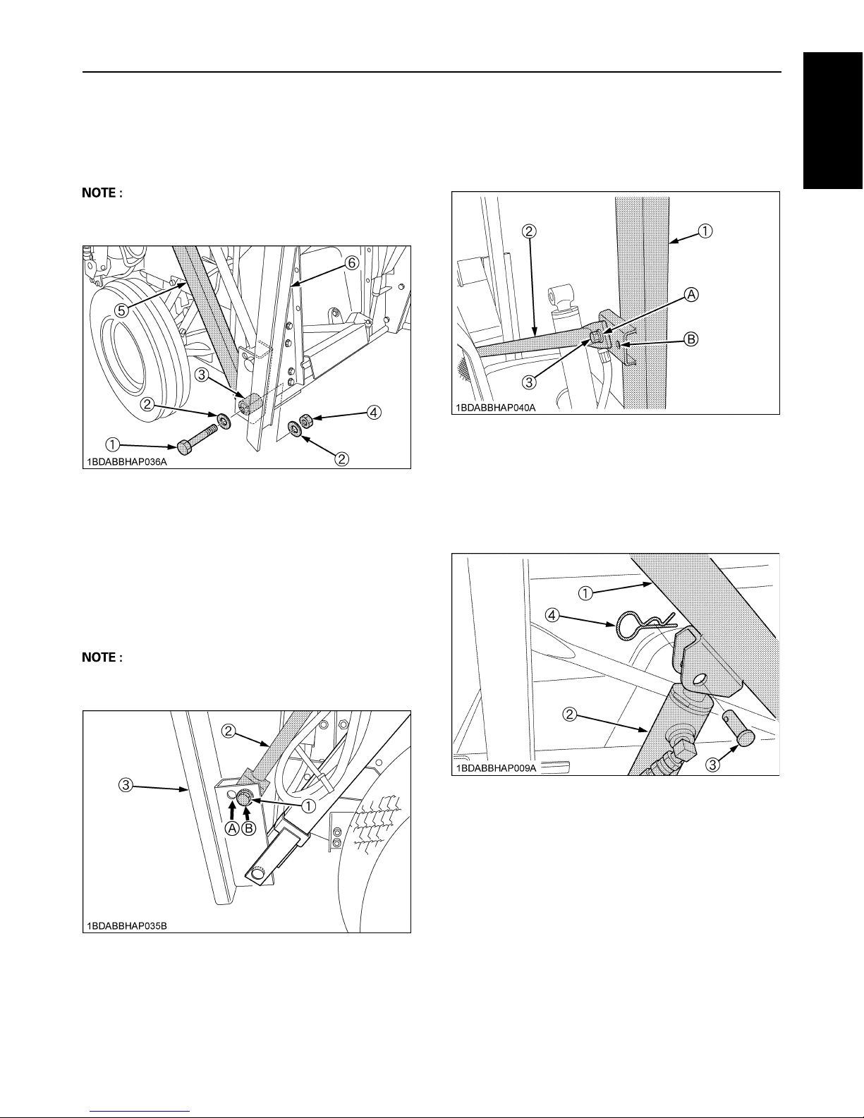
BTightening the Bolts
Tighten up the M14 x 30 bolts (2) (4 pcs. for each side) to
the frame.
Tightening torque: 123.6 to 147.0 N-m (12.6 to 15.0 kgfm)
BInstalling the ROPS Pipe
Use M10 flange bolts and flange nuts to install PIPE
(ROPS) to PIPE, ROPS UNDER as shown in the figure
below.
Tightening torque: 48.1 to 55.9 N-m (4.9 to 5.7 kgf-m)
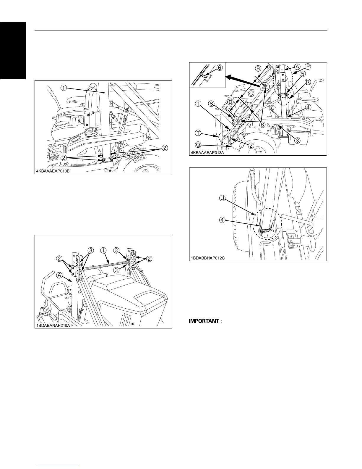
BGZD15-3 HD & GZD21-2 HD Hose Clamp
Positions
A Lift the back base to its top limit and clamp it tightly.
A Make sure the hoses are parallel, not crossing each
other.
A Make sure that the hoses are clamped on the upper lift
arm.
A Move up and down the back base to make sure that
the hoses do not stretch tight (P), nor come into
contact with the lift base and rear tires (Q).
A Be sure to pass the clamp through the Under ROPS
pipe stay and to clamp the hoses. (R)
A Be sure to clamp the sleeve ends of the hoses. (S)
A Be sure to clamp the white-taped zone of the hoses
above the cylinders. (T)
A Be sure to clamp the hoses below the top of the
fenders. (U)
(1) PIPE, ROPS UNDER
(2) Bolt (M14 x 30)
(1) PIPE, ROPS
(2) Flange bolt (M10)
(3) Flange nut (M10)
(A) PIPE, ROPS UNDER
(1) Upper lift arm
(2) Clamp on the bag base
(3) Clamp on the lift cylinder
(4) Clamp below the fender's
top level
(5) Clamp above the check wire
stay level
(6) Clamp on the upper lift arm
(A) Pass close to the headed
pin
(B) 200 mm (reference)
(C) 300 mm (reference)
(D) 200 mm (reference)
11
ENGLISH
<Low Dump>
Assemble the grass catcher container by referring to
GC400HZ grass catcher instruction manual.
INSTALLATION OF TIRE, MOWER, LABEL,
LOW DUMP GRASS CATCHER AND SO ON
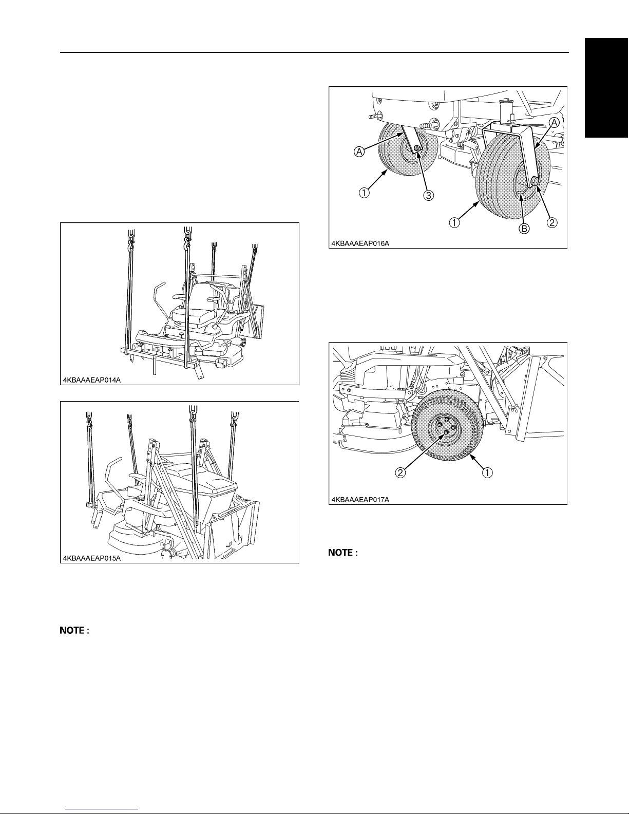
BPutting the Tires
1. Lifting the machine
For the front, apply nylon slings around the front axle.
For the rear, apply nylon slings around the right and
left frames.
2. Putting the front tires
Fix the tire (1) to the front axle with the bolt (2) and nut (3).
Tightening torque: 20 to 25 N-m (2.0 to 2.5 kgf-m)
A When removing the hubcap from the front wheel, be
careful not to drop and lose the collar.
A Direct the wheel bracket backwards and place the tire
(1) with the air valve outwards, as shown below.
A Turn the front tire by hand to make sure it turns
smoothly.
A Insert the bolt (2) from outside and apply the nut (3)
inside.
A Tighten the nut gradually until wheel bearing play is
eliminated and wheel turns freely by hand.
3. Putting the rear tires
Fix the tire (1) to the rear axle with the bolts (2) (4 pcs. for
each side).
Tightening torque: 77.5 to 90.2 N-m (7.9 to 9.2 kgf-m)
A For the tire pressure, refer to the Operator's Manual.
A Place the tire (1) with the air valve outwards.
(1) Tire
(2) Bolt (M12 x 210)
(3) Nut (M12)
(A) Wheel bracket
(B) Air valve
(1) Tire
(2) Bolt
12
ENGLISH
BInstalling the Upper ROPS Pipe
Use 2 set pin assies, locking nuts and bolts to install PIPE,
ROPS UPPER (1) to PIPE, ROPS UNDER.
Tightening torque: 50.0 to 60.0 N-m
5.1 to 6.1 kgf-m
BAdjustment of Foldable ROPS
A Adjust free fall of the ROPS upper frame regularly.
A If you feel less friction when folding the ROPS, tighten
the nut (1) until you feel the right friction in the
movement and then replace the cotter pin.
BInstalling the Front Guard
1. Remove 2 existing bolts. (These bolts will not be
used.)
2. Use 2 bolts, 2 nuts and 2 washers to install GUARD
(FRONT) to the weight bracket as shown in the figure
below.
(1) PIPE, ROPS UPPER
(2) Set pin
(3) BOLT (M16)
(4) NUT (M16)
(1) Nut
(1) Existing bolt (M10)
(1) GUARD (FRONT)
(2) Bolt (M10 x 100)
(3) Nut (M10)
(4) WASHER, SPRING
13
ENGLISH
BInstalling the Seat Belt Assy
As shown in the figures below, install BELT, SEAT, ASSY
(1) to the seat.
BPreparations For Attaching the Mower
Before attaching the mower, set hardware for installation
to frame and covers beforehand.
(1) BELT, SEAT, ASSY
(2) SUPPORT (SEAT BELT)
(3) SQUARE NECK BOLT (M10 x 25)
(4) BOLT (M10 x 20)
(5) Nut (M10)
(6) Washer
(A) 35 5 from
the level
(1) COVER (LH)
(2) COVER (LH 2)
(1) COVER (U/J)
(1) PLATE (BOLT HOLDER 16)
(2) Flange bolt (M8 x 16)
(3) Washer
(H) Hole
 Loading...