

Page 1
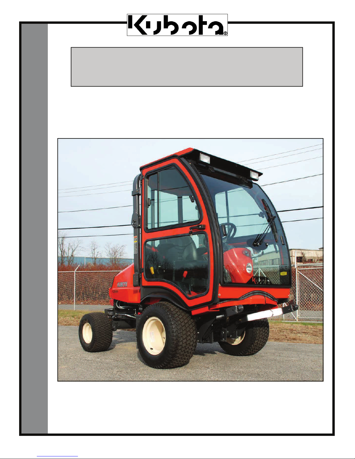
F5205 HARD SIDED CAB KIT
INSTALLATION & OWNER’S MANUAL
The contents of this envelope are the property of the owner.
Be sure to leave with the owner when installation is complete.
Rev. C
p. 1 of 21
Cab is supplied with Work Lights and Windshield Wiper.
INSTALLATION & OWNER’S MANUAL
manual p/n 77700-01874
(revised: 4/1/2013)
Page 2

PAGE 2 OF 21
WARNING WARNING
ordeath.Never operate vehicle if suspicious of Carbon
Monoxide. Inspect exhaust system for leaks monthly. Leaks
can result from loose connections, corrosion, cracks or
other damage to the exhaust manifold. If leaks are found,
repair or replace exhaust system. Do not use vehicle until
ExposuretoCarbonMonoxide
canCauseillness,seriousinjury
weather protection. This cab is not applicable, nor should
the cab be considered as protection against roll over, collision or other accidents that may result. This cab is NOTa
R.O.P.S.cab. Extreme care should be taken when operating and by qualified, experienced operators only.
This cab is designed and manufactured for use only as reasonable
NOTICE
Cabs and accessories add additional weight to the base
vehicle. All accessory weights are listed in product brochures. Deduct the accessory’s total weight from the vehicle’s rated capacity and never exceed the vehicle’s rated
capacity including driver and passenger
CAB INSTALLATION
BEFORE YOU START
HELPFUL REMINDERS:
A. Refer to parts diagram toward the back of this manual to help identify parts during the assem-
bly process.
B. To assist with the cab installation, leave all bolts loose for later adjustment unless otherwise
specified.
C. Read and understand all instructions before beginning.
D. Plastic washers have been supplied to provide a weather seal under the
heads of all exterior bolts. The plastic washer should be installed under
each bolt head directly against the outside cab surface. Care should be
taken not to over tighten the fasteners and damage the plastic washer.
Also use metal washers as required.
E. Apply a clear silicone sealant to seal any minor gaps that may occur
due to vehicle variations.
F. Start all bolts by hand to avoid cross threading.
TOOLS REQUIRED:
Set of standard and metric sockets and open end wrenches
One 21mm socket with long extension
One 3/8” and one 1/2” Drive Ratchet
One 3/16” Allen Wrench
One large Phillips Head Screwdriver
Grease
Electric or cordless drill
9/32” and 3/8” drill bits
Tape measure
Scissors
Wire Crimp Tool
Electrical tape
Fastener
Steel Washer
Plastic Washer
Cab Surface
Page 3
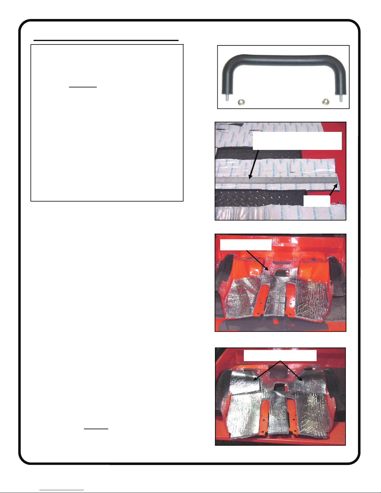
1. DECK SOUND BARRIER
Mounting surface preparation: adhesivebacked sound barrier should be applied to a
clean, dry surface at room temperature. Although the mounting surface may appear
clean, it is required that the surface be cleaned with isopropyl alcohol or an acetone or
ammonia-based cleaner immediately prior
to application of the sound barrier material.
Allow cleaned surfaces to dry thoroughly.
Good surface contact is required to achieve
bond. Failure to follow these steps can result
in the separation of the sound barrier material from the mounting surfaces.
NOTE: paint thinners or products with any
oil in them will not work and are detrimental
to the proper cleaning of the underside of the
fender. NOTE: clean rags are very important. Oily rags will leave residue.
1.1 Remove the ROPS (Roll Over Protection Structure)
structure, the operator seat, the control lever handles, the
differential lock, forward - reverse and brake pedals
from the mower. Remove the operator deck by removing
the two bolts at the back of the deck and the four nuts (2
each side) from the frame supports under the left and
right foot wells. Open the hood, lift the deck up off of the
front mounting studs, tip the back of the deck up and
move to the rear lifting off of the park brake lever and
the steering column cover. Reference Kubota mower
service manual for a more detailed description.
1.2 Remove the grab handle from the left side by removing the two (2) hex nut/washer combinations (SEMS)
from underneath the fender. Discard hardware and handle. See fig. 1.2.
1.3 Position the operator deck upside down on a soft
table to prevent scratching. Remove all 10 plastic pine
tree clips (5/side) that hold the floor mats in place. Discard these 10 small, short plastic clips. 16 larger, longer
plastic pine tree clips are provided in the hardware bag
along with 16 fender washers (1/4” I.D.).
1.4 Note: dry fitting the pieces to get a feel for location
is suggested before peeling back the protective paper.
Place the main piece of sound barrier on a flat table with
the adhesive side up. Cut the center rear section of the
adhesive backing paper 15” from the rear edge as shown
in fig. 1.4.
1.5 Position the main piece of the deck sound barrier in
place as shown in fig. 1.5. Lift up one section at a time,
peel the adhesive backing paper off and adhere the sound
barrier to the deck. DO NOT remove 15” of backing
paper of rear center section that was cut in step 1.4.
1.6 Position the left and right pieces of sound barrier as
shown in fig. 1.6, peel the adhesive backing paper off
and adhere to the deck as shown.
PAGE 3 OF 21
Fig. 1.2 (grab handle)
cut adhesive back paper 15” from
rear edge. (center section only).
rear edge
Fig. 1.4 (modify sound barrier)
Main sound barrier
Fig. 1.5 (main sound barrier)
Left and right sound barrier
Fig. 1.6 (left and right sound barrier)
Page 4
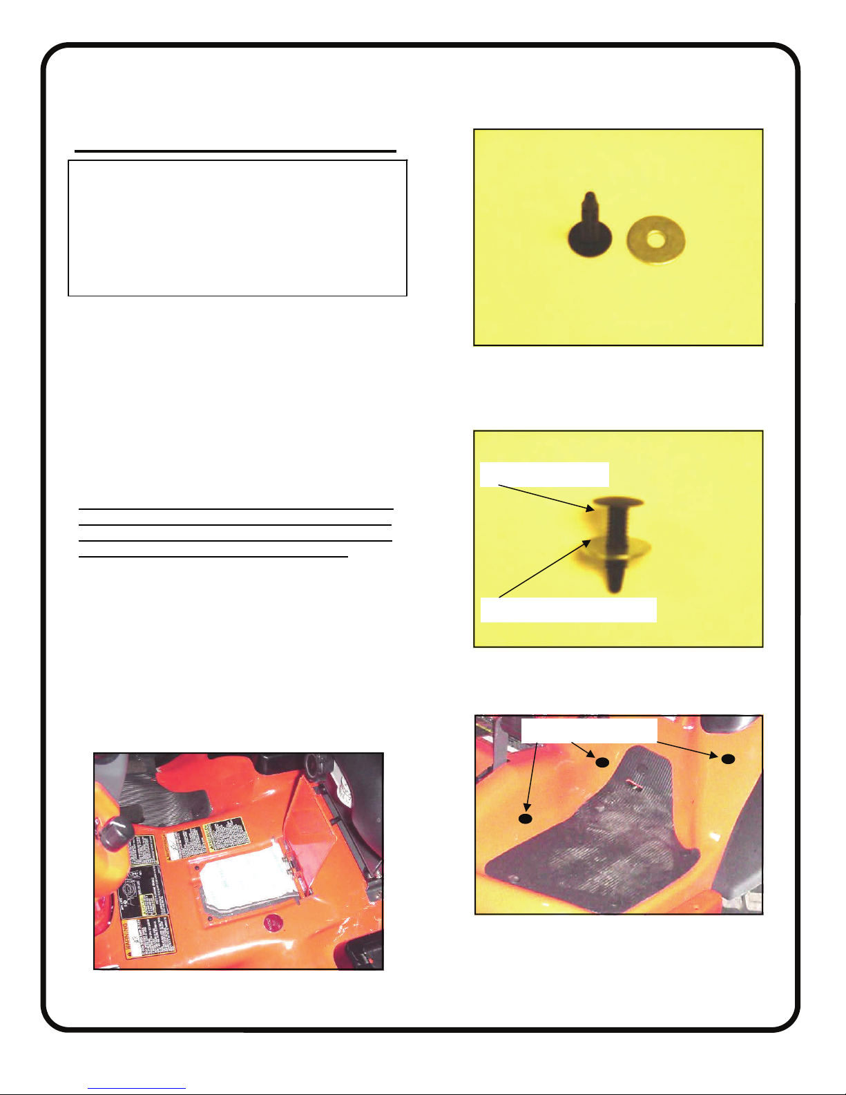
1. DECK SOUND BARRIER (cont’d.)
Use of the supplied plastic pine tree clips and
fender washers (qty.: 16 of ea.) is strongly
advised to help secure the sound material
around the bends in the fender and will help
prevent the sound material from prematurely coming loose. See figures 1.7.1, 1.7.2, and
1.7.3.
1.7 Before re-installing the floor mats, use the 5 existing
holes per fender side as guides to drill 9/32” diameter
holes through the newly installed sound material. Also
drill 3 new holes (9/32” diameter) per side as shown in
figure 1.7.3. Approximate locations are sufficient as
shown. Install 8 plastic pine tree clips per side as shown
with the thin head side up top and the fender washers
below the deck surface sandwiching the sound material
lightly (not shown). Note: no need to over-compress the
sound material with the fender washers.
1.8 Reinstall the deck, pedals, ROPS, and operator seat.
IMPORTANT: the bolts on the ROPS structure must
be torqued properly to meet original equipment safety standards. These four (4) bolts (M14 diameter) are
to be torqued to 91-108 ft.-lbs. (124-147 N-m).
DO NOT install the nuts on the front foot well mounting
studs that were removed in step 1.1, but retain them for
later use. Tuck the slit in the center rear section around
the knob and make sure to pull the seat switch wire up
through the cutout before securing the deck.
1.9 The small piece of sound barrier from the kit can be
stuffed in place under the access door for the transmission filler cap. Do not adhere it to the door. Remove this
piece when checking transmission fluid. See figure 1.9.
PAGE 4 OF 21
Fig. 1.7.1 (loose pine tree clip and fender washer)
Fender would be here
Sound material would be here
Fig. 1.7.2 (assembled pine tree clip and fender washer)
Approximate locations
Fig. 1.9 (transmission filler sound barrier)
Fig. 1.7.3 (view from left front)
Page 5
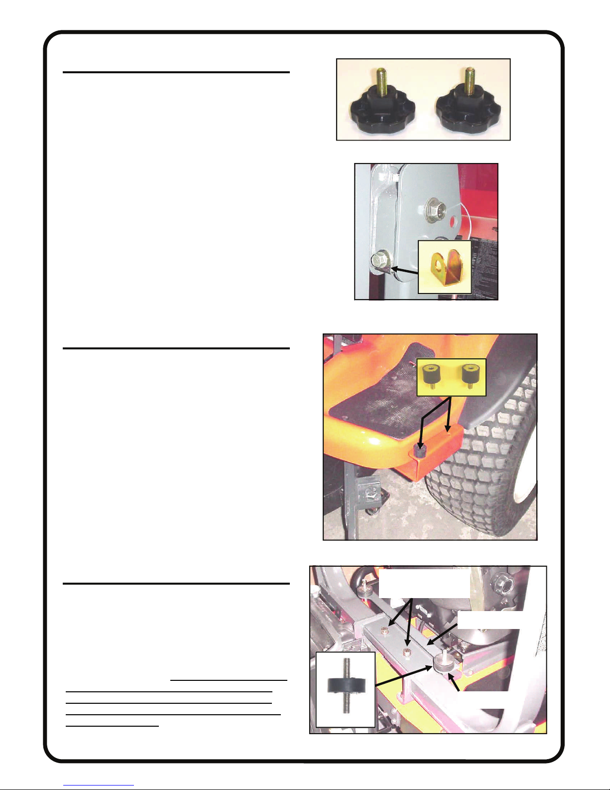
2. VEHICLE PREP.
2.2 Have one 10mm x 1.25 x 20mm long hex head
bolt ready. Remove one of the two large clamping
hand knobs from the middle of the upright of the roll
bar while holding the “U” shaped bracket in place. See
figures 2.2 and 2.2.1. Install the new hex head bolt
through the hole in the “U” shaped bracket and tighten
in place. Note: washers are not used here. Repeat for
opposite side. Discard the hand knobs.
PAGE 5 OF 21
Fig. 2.2 (clamping hand knobs)
Fig. 2.2.1 (view from front of left side)
3. FRONT MOUNTS
3.1 Install two (2) small rubber mounts in the two
outboard holes in the front mount using 5/16” locknuts
and washers as shown in fig. 3.1. Threaded studs pointing down.
3.2 From underneath the vehicle, remove and save
the locknuts and washers from the vertical threaded
weld studs sticking down through the vehicle floorboards (two per side). On the left side, remove and
save the horizontal bolt, washer, and locknut (the rearmost of the two). On the right side, remove and save
the horizontal bolt and washer (the rearmost of the
two) (note: no locknut on right side).
3.3 Position the front mounts onto the threaded studs.
Re-install the horizontal bolts. Note: left side uses a
locknut. Right side has a threaded weld plate instead.
Reinstall the original equipment locknuts and washers.
4. LOWER REAR MOUNT
4.1 Install two (2) large rubber mounts to the upper
tabs in the lower rear mount using 3/8” locknuts and
washers as shown. Remove the two, large 9/16-18 hex
head bolts and lock washers from the vehicle as shown.
Position the lower rear mount in place as shown in figure 4.1. Re-install and tighten the original equipment
hex head bolts and lock washers to secure the lower
rear mount to the vehicle. IMPORTANT: the bolts on
the ROPS structure must be torqued properly to
meet original equipment safety standards. These
two (2) bolts (9/16-18) are to be torqued to 160-192
ft.-lbs. (217-260 N-m).
Fig. 3.1 (view from front of left side)
remove and re-install
these two bolts
lower rear mount
rubber mount
Fig. 4.1 (view from rear of right side)
Page 6
PAGE 6 OF 21
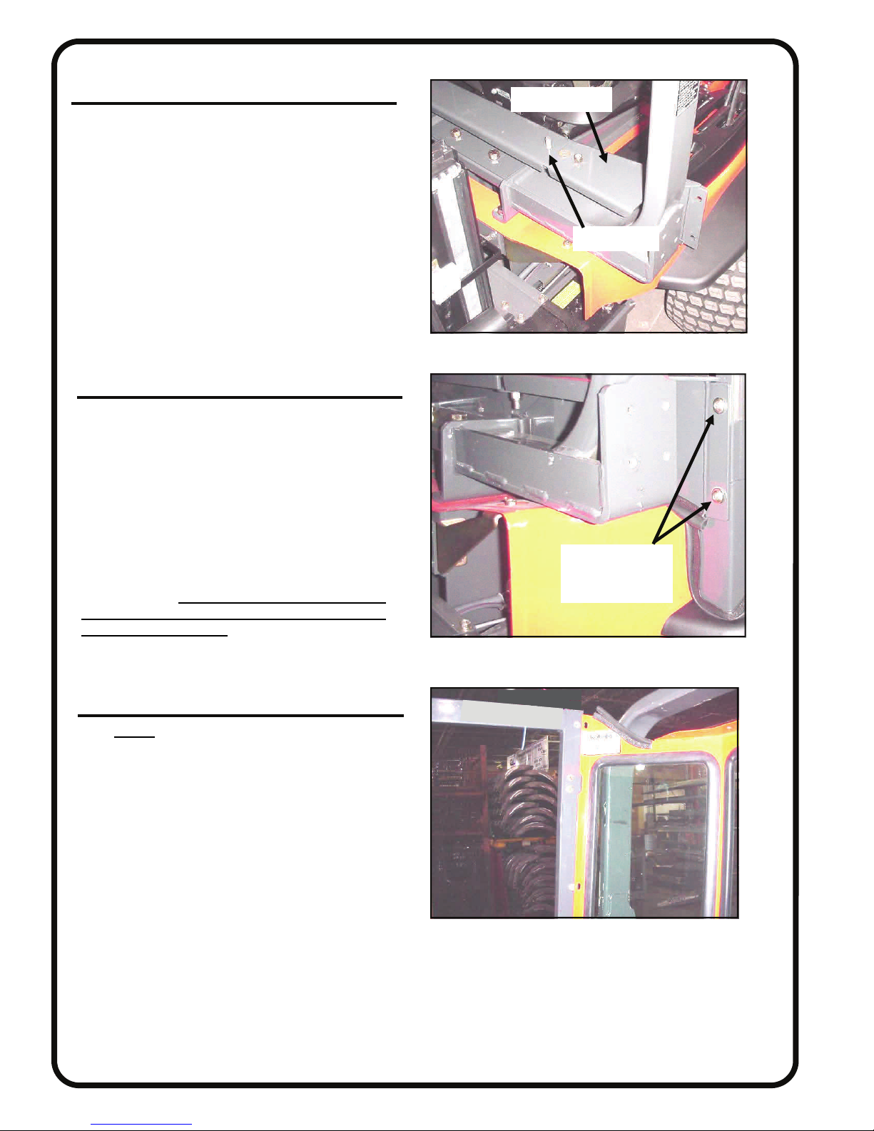
5. LOWER REAR PANEL
5.1 With assistance, install the lower rear panel onto
the threaded shafts of the two rubber bumpers. Use
3/8” locknuts and washers as shown in fig. 5.1. Tighten
both locknuts.
5.2 Do not peel off the backing paper on the sound
barrier material until step 7 (just prior to installing the
upper rear panel assembly).
6. RIGHT SIDE FRAME
6.1 With assistance, remove the doors from both
side frames by opening and lifting up off of the pin
hinges. Next, position the right side frame so that two
of the holes in the floorboard of the side frame line up
with the threaded inserts in the two front rubber bumpers. Loosely install two 5/16” x 3/4” long button head
bolts and two steel washers. Do not tighten bolts. Attach the rear of the side frame to the lower rear panel
using two 5/16” x 3/4” long button head bolts, two
plastic washers, and two steel washers (see fig. 6.1).
Note: the side frame tubing has factory installed
threaded inserts. CAUTION: to avoid cross thread-
ing the factory installed threaded inserts, start the
bolts by hand (no tools). Do not tighten these bolts
yet. The other side frame will be installed in step 7
(after the rear panel is positioned).
lower rear panel
threaded stud
Fig. 5.1 (view from rear of right side)
button head bolts,
plastic washers,
and steel washers
Fig. 6.1 (view from rear of right side)
7. REAR PANEL & LEFT SIDE FRAME
7.1 NOTE:The rear panel must be positioned in
place at this time because clearances will not allow
it to be put in place after side frame installation.
7.2 At this time, peel back the narrow protective sheet
remaining on the sound barrier of the lower rear panel.
Fold it down on to the 90 degree bend of the lower rear
panel. Note: adhesive-backed sound barrier should be
applied to a clean, dry surface at room temperature.
7.3 With assistance, place the rear panel in position
and rest it against the ROPS (see fig. 7.1).
7.4 With assistance, install the left side frame so that
two of the holes in the floorboard of the side frame line
up with the threaded inserts in the two front rubber
bumpers. Loosely install two 5/16” x 3/4” long button
head bolts and two steel washers. Do not tighten bolts.
7.5 Attach the rear of the side frame to the lower rear
panel using two 5/16” x 3/4” long button head bolts,
two plastic washers, and two steel washers (as shown
in figure 6.1). Do not tighten bolts.
Fig. 7.1 (view from front of left side)
Page 7
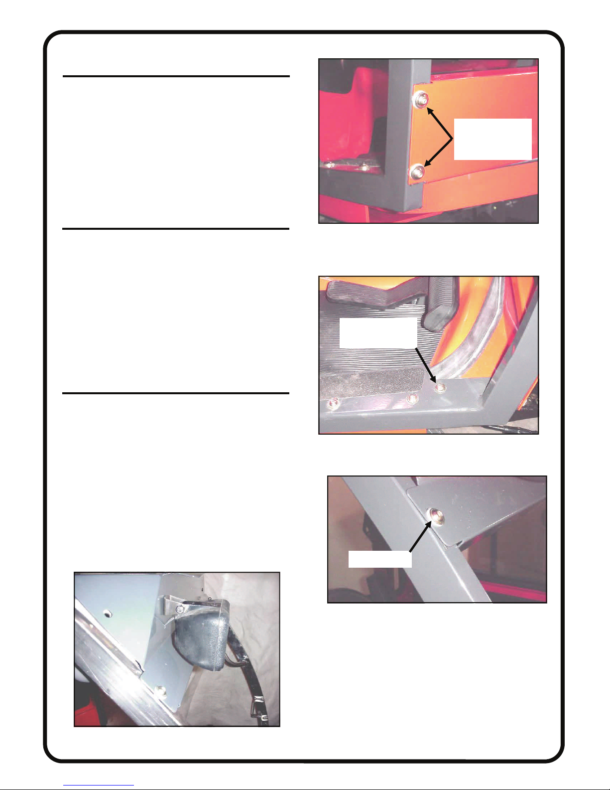
8. COWL
8.1 With assistance, install the cowl to the lower front
of the side frames. Use two 5/16” x 3/4” long button
head bolts, two steel washers, and two plastic washers
per side to connect to the factory installed threaded
inserts in the side frame tubing. See fig. 8.1. Install one
5/16” x 3/4” long button head bolt, two steel washers,
and one locknut through the floorboard with the head
of the bolt up top as shown in fig. 8.1.1. Repeat for
opposite side. Leave bolts loose.
9. WINDSHIELD SUPPORT
9.1 With assistance, install the windshield support to
the upper front of the side frames. Use one 5/16” x
3/4” long button head bolt, one steel washer, and one
plastic washer in the lower hole on each side of the
windshield support (into the factory installed threaded
insert in the side frame tubing). See fig. 9.1. Install two
5/16” x 3/4” long button head bolts, four steel washers,
two plastic washers, and two locknuts to the middle
and upper holes in the windshield support. Locknuts to
be towards the inside of the cab. Repeat for opposite
side. Leave bolts loose.
10. WORK LIGHTS
10.1 Install the two supplied grommets in the lower of
the two holes in the front face of the windshield support. Install the work light bolts into the upper of the 2
holes in the windshield top. Run the wires through the
holes with grommets below as shown in Figure 10.1.
(Note: The work lights are mounted upside down)
PAGE 7 OF 21
button head bolts,
plastic washers,
and steel washers
Fig. 8.1 (view from front of right side)
bolt through cowl
(bolt head up top)
Fig. 8.1.1 (view from front of right side)
Fig. 10.1 (view from front of right side)
plastic washer
Fig. 9.1 (view from front of right side)
Page 8
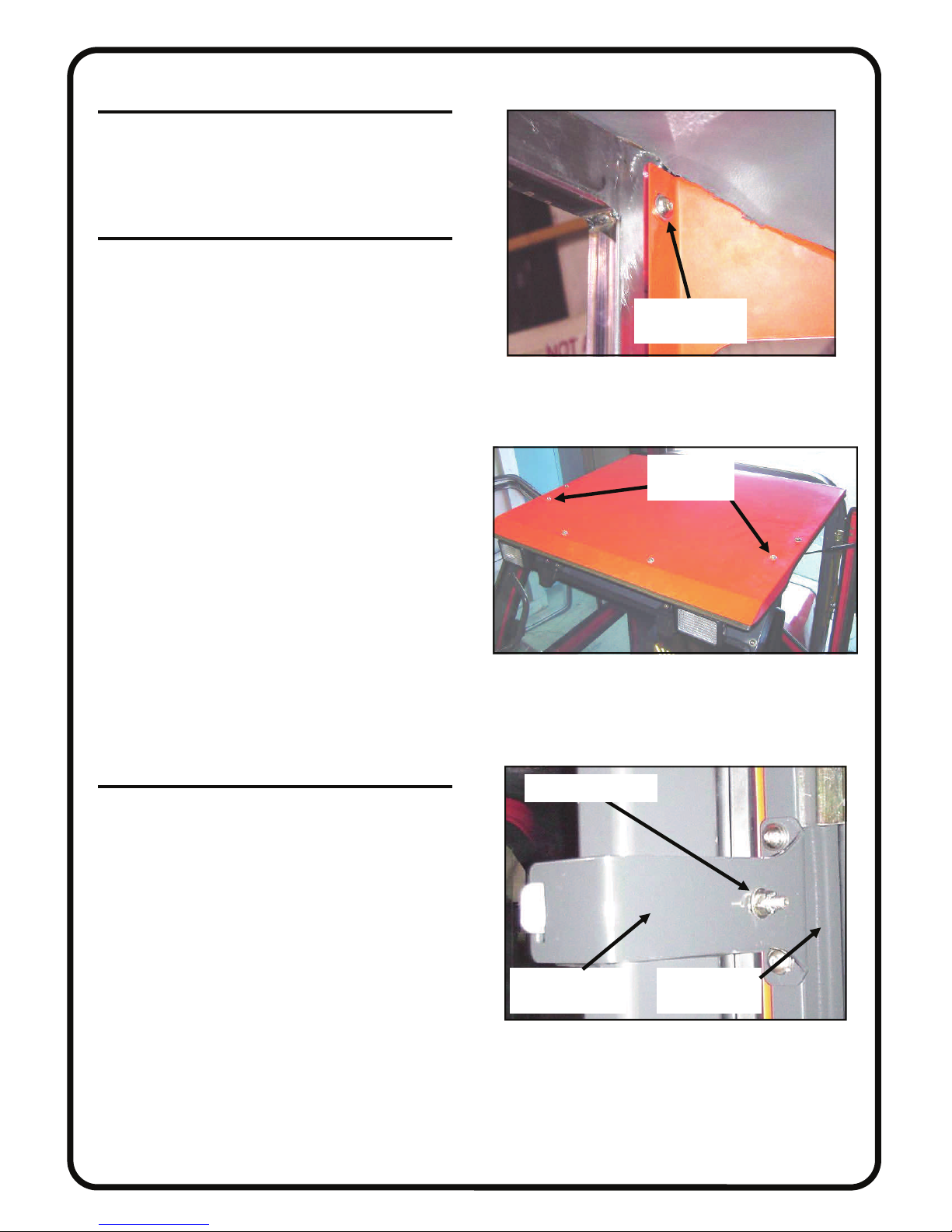
11. REAR PANEL
11.1 Attach rear panel to the left and right side frames
with eight 5/16-18 x 3/4” long button head bolts and
steel washers (four per side) into factory installed
threaded inserts. See figure 11.1.
12. ROOF
12.1 Remove the tethered pins and tip the folding
ROPS to the rear being careful not to scratch the rear
panel. Install the roof so that the visor portion is facing
forwards (see fig. 12.1).
(Note: For easier installation, use a screwdriver to
puncture through the foam headliner on the roof
through each of the bolt holes before installing. Do
this from the inside to prevent any unwanted tearing.)
12.2 Install one 5/16” x 3/4” long button head bolt,
with one steel washer, and one plastic washer each on
the left and right side of the roof into factory installed
inserts, in the top, front section of the side frames.
12.3 Use two 5/16” x 1” long button head bolts, four
steel washers, two plastic washers, and two locknuts
for the two holes directly in front of the two bolts installed previously. The locknuts should be underneath
the roof.
12.4 Use two 5/16” x 3/4” long button head bolts,
four steel washers, two plastic washers, and two locknuts for the two front holes, locknuts to be underneath
the roof.
12.5 Use six 5/16” x 3/4” long button head bolts,
twelve steel washers, six plastic washers, and six locknuts for the four rear holes, locknuts to be inside the
cab.
12.6 Lift folding portion of ROPS back into position
and re-install the tethered pins, including the cotter
pins.
13. ROLL BAR BRACKETS
13.1 Attach the larger half of the two piece roll bar
bracket assembly to the rear of the side frame using
two 5/16” x 3/4” long button head bolts and two steel
washers. Orient as shown in fig. 13.1. Do not tighten
bolts. Assemble the other half by inserting the tab into
the slot. Install one 5/16” x 3/4” long carriage bolt, one
steel washer, and one locknut so that the locknut and
washer are on the outside as shown.
PAGE 8 OF 21
button head bolt
and steel washer
Fig. 11.1 (viewed from front of left side)
1” button
head bolts
Fig. 12.1 (viewed from front of left side)
washer and locknut
larger half of
roll bar brackets
outside surface
of side frame
Fig. 13.1 (view from rear of right side)
Page 9
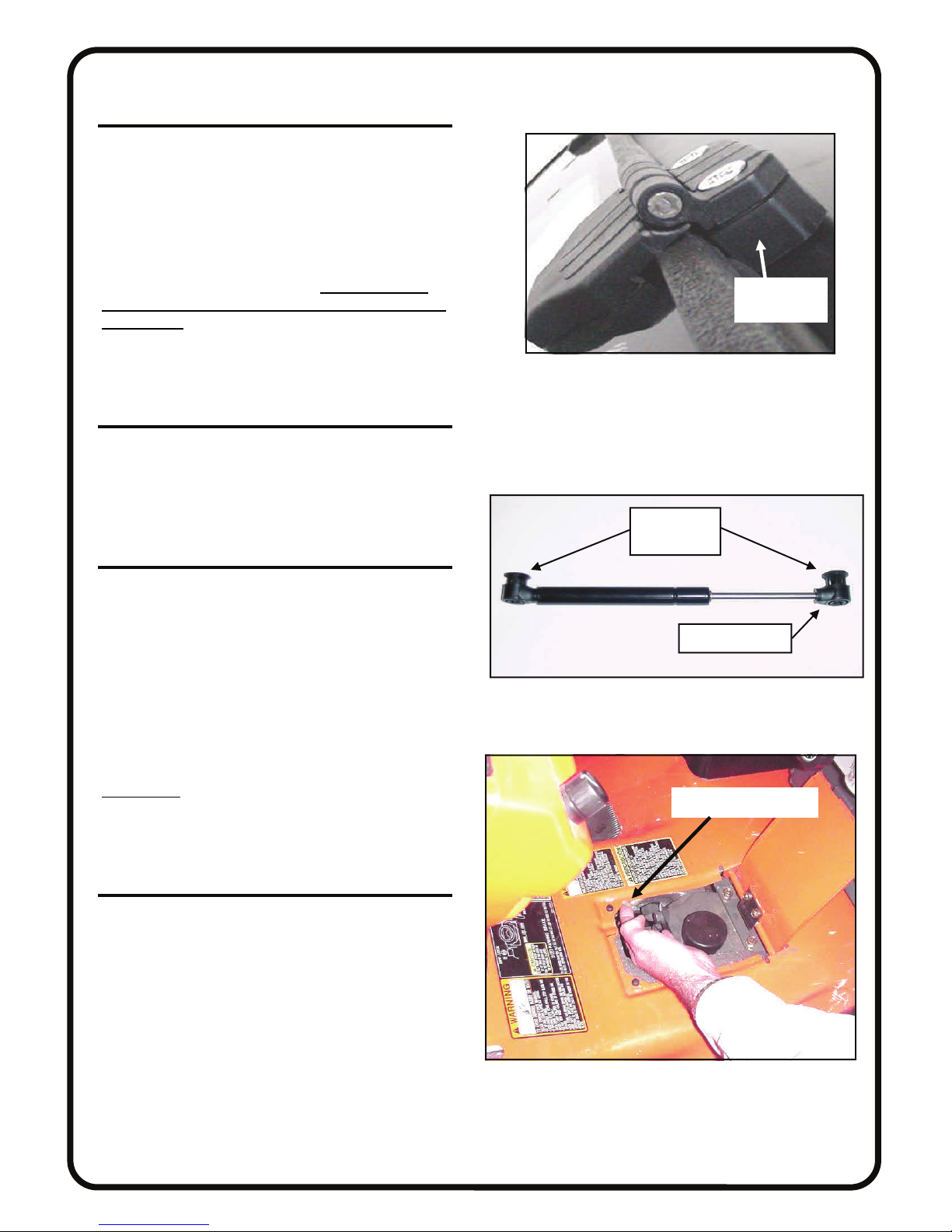
14. WINDSHIELD
14.1 Install the 3/4” thick plastic spacers onto the wind-
shield hinges and insert four 5/16” x 1 3/4” long flat
head bolts. See figure 14.1.
14.2 With assistance, lift the windshield in place and
engage the bolts into the slots. Attach 5/16” steel washers and 5/16” locknuts to the inside. Align the sides of
the windshield with the side frames, engage both windshield latches in the closed position, then tighten the four
flat head bolts in the upper hinges. Note: hinges are
plastic components. Do not overtighten. Torque to 7
ft./lbs. max..
14.3 The left and right windshield latches can engage in
three positions: closed, open 1”, or open 2” at the bottom.
15. TIGHTEN ALL BOLTS
15.1 Tighten all bolts at this time. First tighten the roll
bar brackets and the lower rear panel bolts that go into
the back of the sideframes. Then work from the front to
the rear. (lower front of side frames, cowl, windshield
support, roof, then rear panel.)
16. DOORS
16.1 Apply grease to the pins mounted on the doors.
With assistance, install the doors pins into the sleeves on
the sideframes. Work the doors back and forth until the
hinges are completely seated. Note: the hinges, and
striker pin can be adjusted for proper engagement. The
rotary latch should be adjusted to get two (2) “clicks”
when latching.
16.2 Install the gas shock to the side frame and door
with the small piston end towards the door. Press the
button on the compression fastener to lock the gas shock
to the ball stud. See figure 16.2.
CAUTION: for safe operation, do not drive with
doors open. Make sure doors are closed and properly
latched when driving.
17. FINAL WIRING
17.1 Connect the ring terminals on the wire harness
containing the relay and fuse to the respective colored
battery posts. (Red to positive; black to negative) The
red terminal can be re-tightened, but leave the black terminal loose because more wires will be attached in later
steps. Stretch the harness forward and connect the male
bullet terminal on the end of the purple wire to the female bullet terminal on the vehicle wire harness. This is
located on a pigtail under the deck near the HST dipstick
and filler cap. See fig. 17.1.
PAGE 9 OF 21
3/4” thick
plastic spacer
Fig. 14.1 (view from front of left side)
compression
fasteners
this end on door
Fig. 16.2 (gas shock for hard sided doors)
female bullet terminal
Fig. 17.1 (view from left side of vehicle)
Page 10
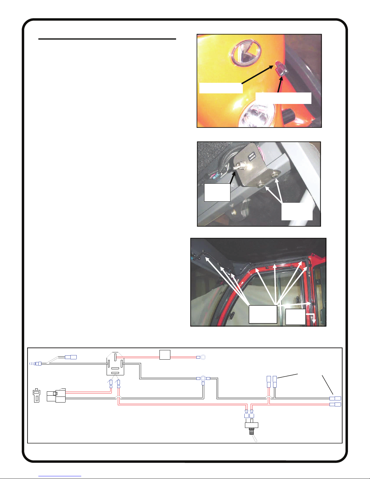
17. FINAL WIRING (cont’d.)
17.2 Route the wiper wire harness (black plug on one
end) down the steering column and back to the battery.
Drill a 3/8” hole in the vehicle steering column cover
(Note: Be sure to check for clearance inside the column, do not drill too deep) and feed the harness
through the hole, and down the inside of the steering
column. (Note: A wire hook or snake can be used to
pull the wire down through the column easily) Leave
8” out of the hole so there is enough wire to open the
windshield. Route the wires back to the battery. Be
careful to avoid any moving parts which may pinch or
sever the wires. Crimp the supplied ring terminal to
the end of the black wire. See fig. 17.2.
17.3 Attach the toggle switch bracket to the passenger
side of the windshield support using two 1/4-20 x 3/4”
hex head bolts, four 1/4” steel washers, and two 1/4-20
locknuts. See Fig. 17.3.
17.4 Locate the wire harness with the toggle switch.
Remove the nut on the toggle switch and put the toggle
switch through the hole in the mount. Make sure that
the groove on the toggle switch is at the bottom of the
hole so that the point that is laser cut in the hole keeps
the switch from spinning. Reinstall the nut and tighten.
17.5 Connect the two sets of female bullet connectors
to the male bullet connectors on the work lights.
17.6 Attach the adhesive cable tie mounts to the cab
as shown in Fig. 17.6. (3 on the windshield support, 3
on the side frame, and 4 down the side of the rear panel). Starting at the driver’s side work light, neatly cable tie the wires to the vehicle.
17.7 Route the wires out the hole in the bottom corner
of the cab between the fender and sideframe. Connect
the three ring terminals on the black wires from the
three harnesses to the negative battery post and tighten.
Connect the two piggy back terminals together from
the work light and wiper harnesses and wrap electrical
tape around them leaving the end open. Attach them to
the outermost open post on the relay. Secure all wires,
the relay, and the fuse to the vehicle with cable ties so
that they cannot catch on any moving parts.
17.8 See Fig. 17.8 for a full wiring schematic.
3/8” drilled hole
wiper wire connector
Fig. 17.2 (viewed from front right side)
Toggle
Switch
head bolts
Fig. 17.3 (viewed from rear right side)
Cable Tie
Holders
Fig. 17.6 (viewed from rear right side)
PAGE 10 OF 21
1” button
2 Not
Shown
Signal Wire (purple)
Piggybacks (Red)
Wiper Plug
Relay
25A
Battery Positive (Red)
Battery Negative (Black) To Worklights
Toggle Switch
Fig. 17.8 (wiring schematic)
Page 11
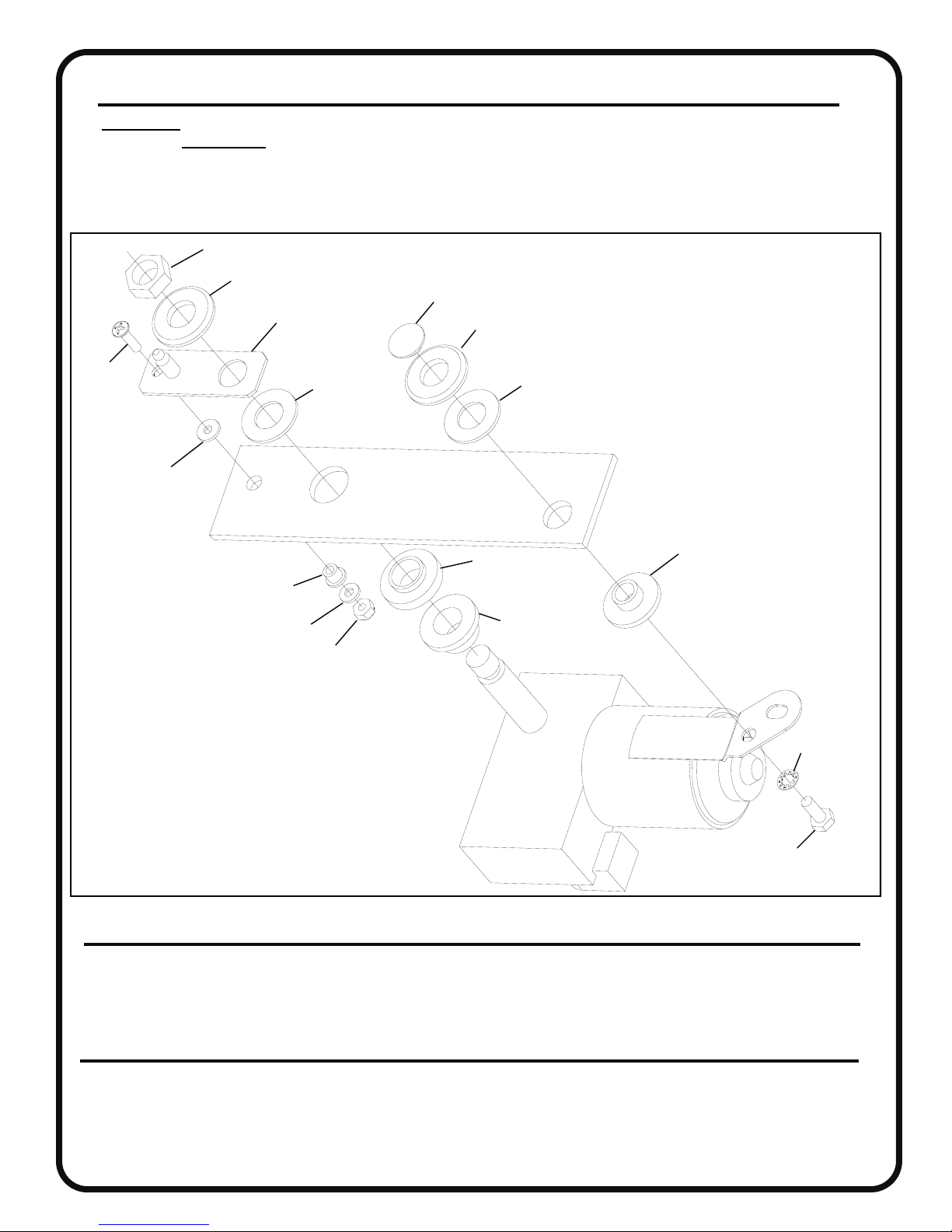
PAGE 11 OF 21
18. WINDSHIELD WIPER
CAUTION: Make sure that the metal parts of the wiper motor do not contact the glass during installation. Damage
could occur. WARNING: Over tightening wiper mounting hardware can damage windshield and components.
18.1 Install the pantograph wiper motor as shown below in figure 18.1. Install blade to arm and arm to wiper motor.
A factory installed set screw has been provided to ensure that the arm does not work its way off the splined shaft of
the motor. Tighten that one set screw to 2 foot-pounds max. (or 24 inch-pounds max.).
Hex Nut
Plastic Cup Washer
Pantograph
Wiper Mount
1/4-20 Cap Nut
Plastic Cup Washer
10-32 x 3/4”
Bolt
Small Rubber
Washer
Small White
Nylon Bushing
Steel Washer
10-32 Locknut
Large
Rubber
Washer
Windshield
Large Rubber Washer
Large White
Nylon Bushing
Black Plastic
Standoff
Medium White
Nylon Bushing
Internal tooth
lock washer
Fig. 18.1 (wiper motor installation)
19. FINISHING TOUCHES
19.1 Install nut covers on all exposed nuts inside the cab. Also install on the nut protruding from the roll bar brackets.
19.2 Cut the supplied grit paper to fit on each of the side frame floorboards to prevent slipping when entering or exiting
the cab. Adhere the grit paper to a clean dry surface at room temperature.
20. CARE AND MAINTENANCE
20.1 Check and tighten hardware after 40 hours of operation. Periodically inspect and tighten hardware for the remainder
of the unit’s life.
20.2 Wash the painted surfaces of the unit with commercial automotive cleaning products.
20.3 Clean windows with glass cleaner.
1/4-20 x 5/8” Bolt
Page 12
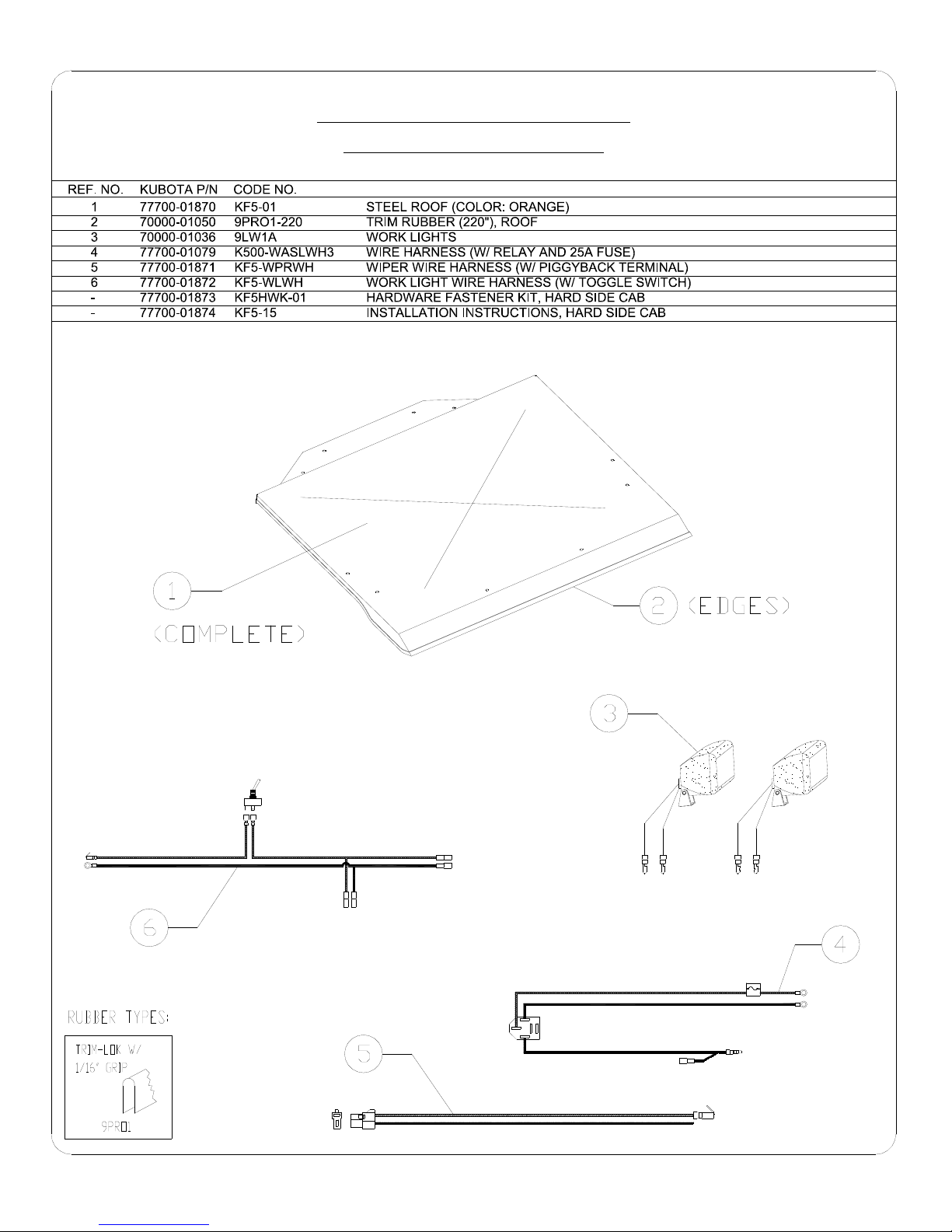
F5205 HARD SIDED CAB KIT
PARTS LIST FOR ROOF
DESCRIPTIONQTY.
1
1
2
1
1
1
1
1
P. 12 OF 21
Page 13
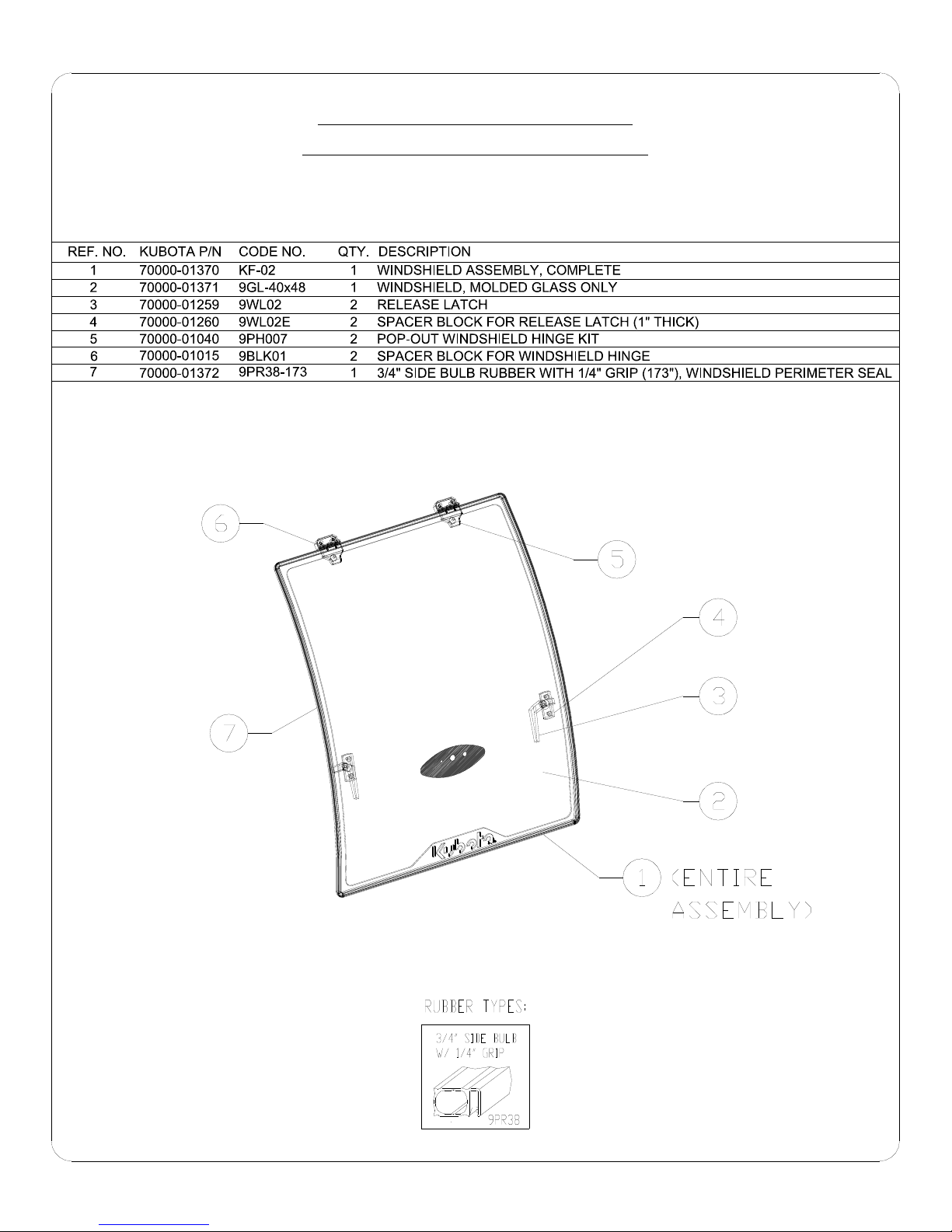
F5205 HARD SIDED CAB KIT
PARTS LIST FOR WINDSHIELD
P. 13 OF 21
Page 14
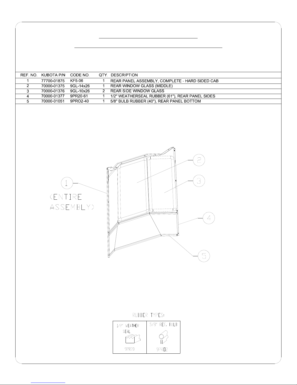
F5205 HARD SIDED CAB KIT
PARTS LIST FOR REAR PANEL ASSEMBLY
P. 14 OF 21
Page 15
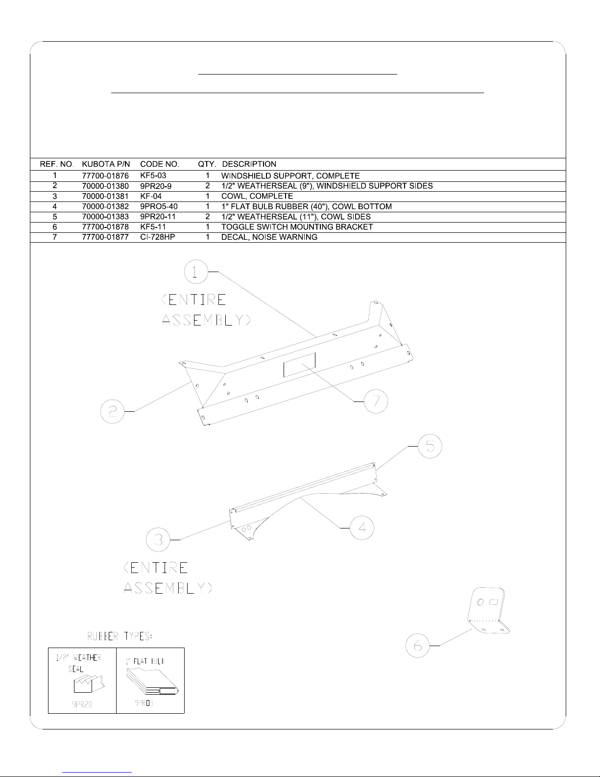
F5205 HARD SIDED CAB KIT
PARTS LIST FOR WINDSHIELD SUPPORT AND COWL
P. 15 OF 21
Page 16
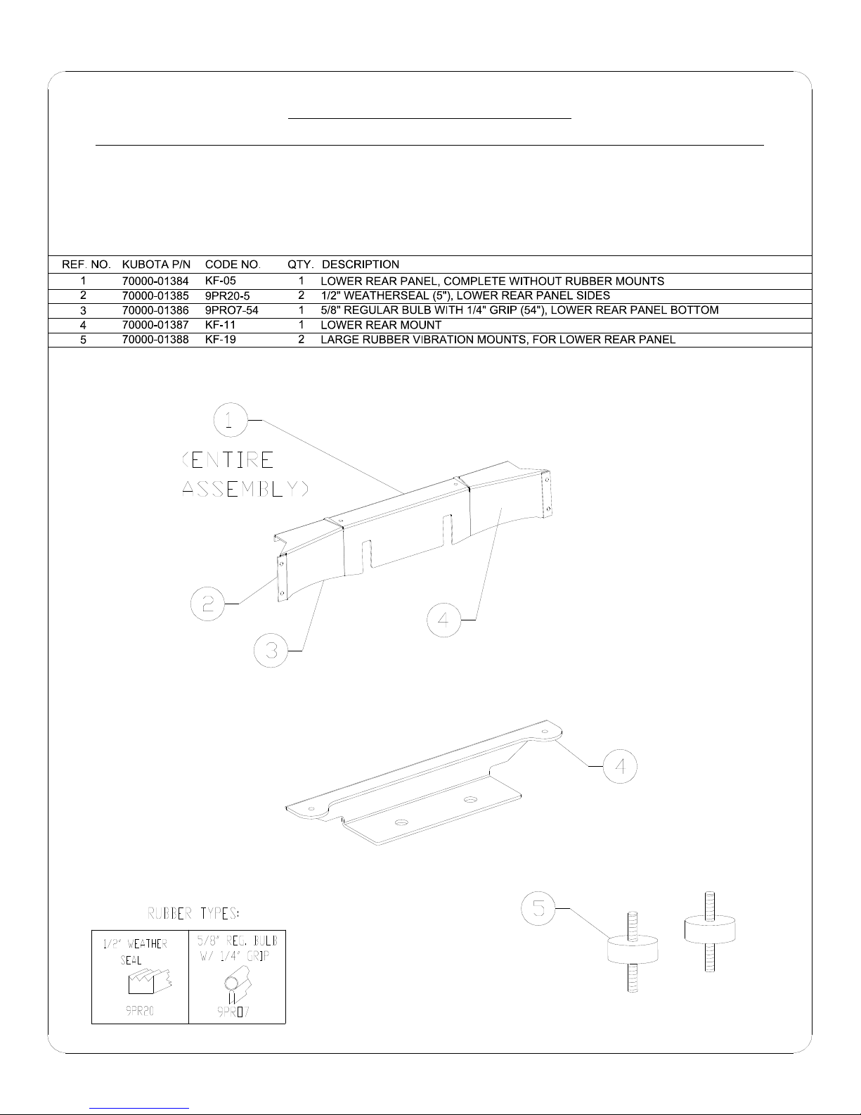
F5205 HARD SIDED CAB KIT
P. 16 OF 21
PARTS LIST FOR LOWER REAR PANEL AND LOWER REAR MOUNT
Page 17
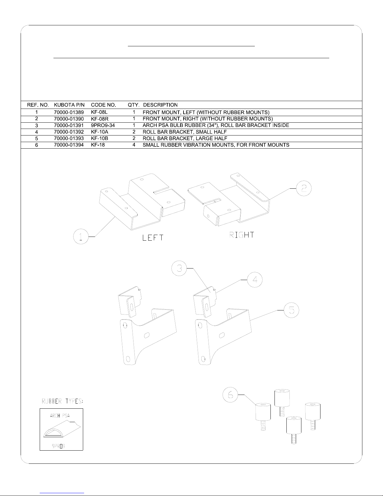
F5205 HARD SIDED CAB KIT
PARTS LIST FOR FRONT MOUNTS AND ROLL BAR BRACKETS
P. 17 OF 21
Page 18
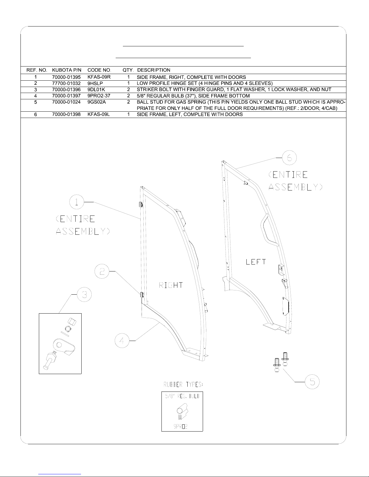
F5205 HARD SIDED CAB KIT
PARTS LIST FOR SIDE FRAMES
P. 18 OF 21
Page 19
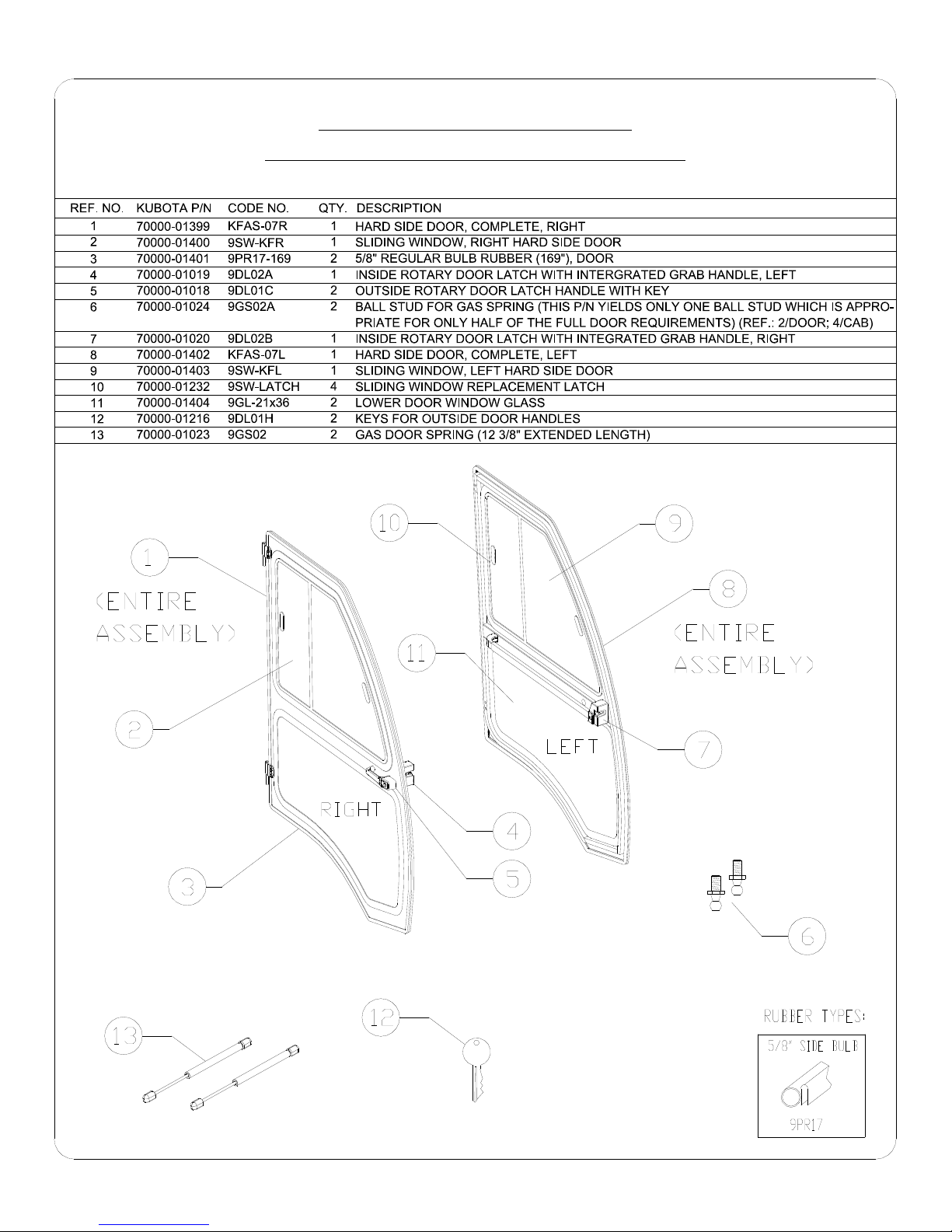
F5205 HARD SIDED CAB KIT
PARTS LIST FOR HARD SIDED DOORS
P. 19 OF 21
Page 20
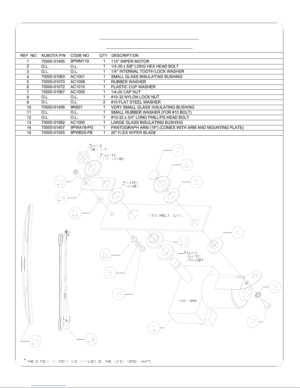
O.L. = obtain locally
F5205 HARD SIDED CAB KIT
PARTS LIST FOR WIPER
P. 20 OF 21
Page 21
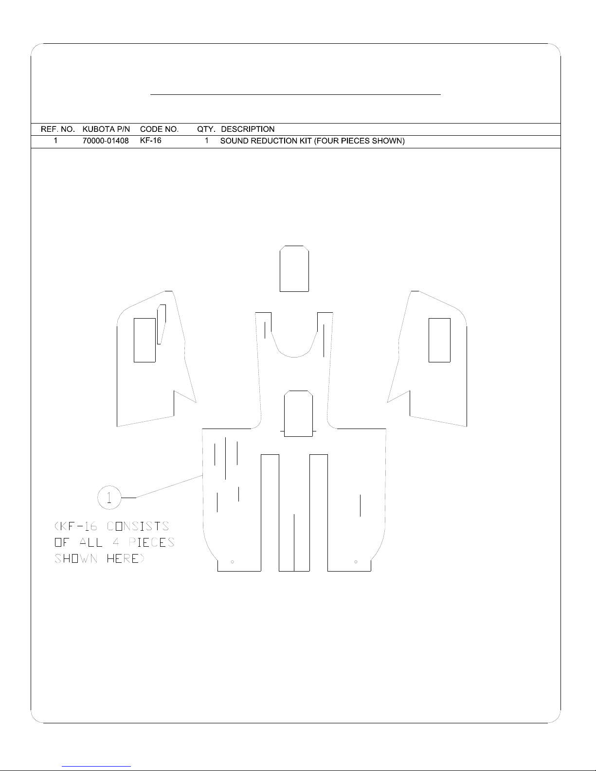
PARTS LIST FOR SOUND REDUCTION KIT
P. 21 OF 21
 Loading...