

KTV Global LTD102AA Users manual

THIS PRODUCT HAS BEEN DESIGNED, MANUFACTURED AND
INSPECTED IN COMPLIANCE WITH THE
ISO9001 QUALITY ASSURANCE SYSTEM.
Part No. 11907070B
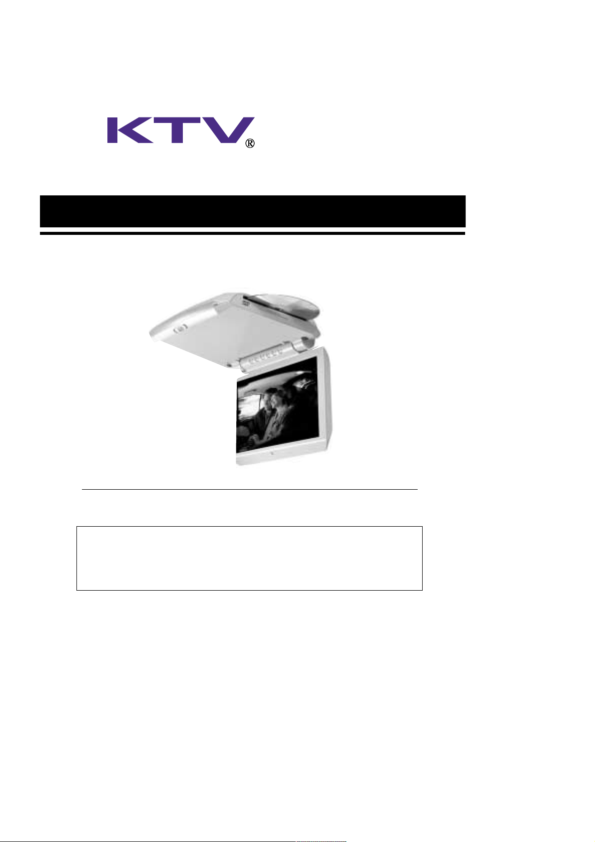
10.2” LCD INTEGRATED DVD MONITOR RECEIVER SYSTEM
INSTALLATION INFORMATION
& OPERATING INSTRUCTIONS
IMPORTANT NOTE :
WHEN USED IN A VEHICLE, THIS SYSTEM IS INTENDED PRIMARILY AS A MONITOR FOR THE BUILT-IN
DVD PLAYER OR FOR AN EXTERNAL DVD PLAYER, VIDEOCASSETTE PLAYER, VIDEO GAME, OR
CAMERA. TELEVISION BROADCAST RECEPTION WILL BE ADVERSELY AFFECTED BY CONDITIONS SUCH
AS MOTION, CHANGE OF DIRECTION, ATMOSPHERIC ACTIVITY, AND LOCAL SURROUNDINGS.
IT IS THEREFORE LIKELY THAT BROADCAST PICTURE QUALITY WILL BE MARGINAL WHEN THIS
SYSTEM IS USED IN A MOBILE ENVIRONMENT.
MOBILE
APPLICATIONS
MODEL:
LVMD-102/LVMD-102S
THIS PRODUCT IS INTENDED FOR PROFESSIONAL INSTALLATION ONLY
FOR MOBILE-SPECIFIC 12 VOLT DC-ONLY OPERATION
PLEASE READ ALL INSTRUCTIONS BEFORE USING THIS PRODUCT
CAUTIONS
2
FCC WARNINGS :
This equipment may generate or use radio frequency energy. Change or modifications to this
equipment may cause harmful interference unless the modifications are expressly approved
in the instruction manual.
The user could lose the authorization to operate this equipment if an unauthorized change or
modification is made.
CAUTION
RISK OF ELECTRIC SHOCK
DO NOT OPEN
DO NOT OPEN ELECTRIC SHOCK.
DO NOT REMOVE COVER (OR BACK)
NO USER-SERVICEABLE
PARTS INSIDE.
REFER SERVICING TO
QUALIFIED SERVICE PERSONNEL
CAUTION :
ANY CHANGES OR MODIFICATIONS IN THE CONSTRUCTION OF THIS DEVICE WHICH ARE NOT
EXPRESSLY APPROVED BY THE PARTY RESPONSIBLE FOR COMPLIANCE COULD VOID THE
USER'S AUTHORITY TO OPERATE THE EQUIPMENT.
WARNINGS :
TO PREVENT FIRE OR SHOCK HAZARD, DO NOT EXPOSE THIS UNIT TO RAIN OR MOISTURE.
DO NOT OPEN THE CABINET. DANGEROUS HIGH VOLTAGE IS PRESENT. SERVICING SHOULD
ONLY BE PERFORMED BY QUALIFIED PERSONNEL.
THIS LCD VIDEO SYSTEM SHOULD ONLY BE OPERATED WITH 12V DC.
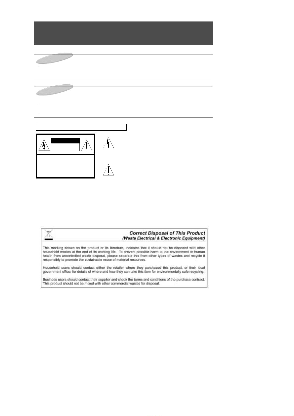
GRAPHICAL SYMBOLS EXPLANATION
This lightning flash with arrowhead symbol, within an
equilateral triangle is intended to alert the user to the
presence of uninsulated "dangerous voltage" within the
product's enclosure that may be of sufficient magnitude to
constitute a risk of electric shock to persons.
The exclamation point within an equilateral triangle is
intended to alert the user to the presence of important
operating and maintenance (Servicing) instructions in the
literature accompanying the appliance.

IMPORTANT SAFEGUARDS
3
1. Read Instructions All safety & operating instructions should be read before operating the appliance.
2. Retain Instructions The safety and operating instructions should be retained for future reference.
3. Heed Warnings Adhere to ALL warnings on the product and in the operating instructions.
4. Follow Instructions All operating and use instructions should be followed.
5. Cleaning Unplug this product from power cable connector before cleaning. Do not use liquid cleaners or
aerosol cleaners. Use a damp cloth for cleaning.
6. Attachments Do not use attachments not recommended by the product manufacturer as they may cause
hazards.
7. Water and Moisture Do not install this product near water - for example, near a bath tub, washbowl,
kitchen sink or laundry tub; in a wet basement; or near a swimming pool and the like.
8. Accessories Do not place this product on an unstable cart, stand, tripod, bracket, or table. The product
may fall, causing serious injury to a child or adult, and serious damage to the equipment.
Use only with a cart, stand, tripod, bracket, or table recommended by the manufacturer, or sold with the
product. Any mounting of the product should follow the manufacturer's instructions, and should use a
mounting approved by the manufacturer.
9. A product and cart combination should be moved with care. Quick stops, excessive force, and uneven surfaces may cause the product and cart combination to overturn.
10. Ventilation Slots and opening in the cabinet are provided for ventilation and to
ensure reliable operation of the product and to protect it from overheating and these
should never be blocked by placing the product on a bed, sofa, rug, or other similar
surface. This product should not be placed in a built-in installation such as a bookcase or rack unless proper ventilation such as a bookcase or rack unless proper
ventilation is provided or the manufacturer's instructions have been adhered to.
11. Power Sources This product should be operated only from the type of power source indicated on the
marking label. lf you are not sure of the type of power supply to your car, consult your product dealer. For
products intended to operate from battery power, or other source, refer to the operating instructions.
12. Servicing Do not attempt to service this product yourself as opening or removing covers may expose you
to dangerous voltage or other hazards. Refer all servicing to qualified service personnel.
13. Damage requiring Service Unplug this product the wall outlet and refer servicing to qualified service per-
sonnel under the following conditions :
a. When the power-supply cord or plug is damaged.
b. lf liquid has been supplied, or objects have fallen into the product.
c. lf the product has been exposed to rain or water.
d. If the product does not operate normally by following the operating instructions. Adjust only those
controls that are covered by the operating instructions as an improper adjustment of other controls may
result in damage and will often require extensive work by a qualified technician to restore the product to
its normal operation.
e. lf the product has been dropped, or the cabinet has been damaged.
f. When the product exhibits a distinct change in performance-this indicates a need for service.
14. Replacement Parts When replacement parts are required, be sure the service technician has used
replacement parts specified by the manufacturer or that have the same characteristics as the original
part.Unauthorized substitutions may result in fire, electric shock or other hazards.
15. Safety Check Upon completion of any service or repairs to this video product, ask the service technician
to perform safety checks to determine that the video product is in proper operating condition.
16. Wall or Ceiling Mounting The product should be mounted to a wall or ceiling only safety recommended
by the manufacturer.
17. Heat The product should be situated away from heat sources such as radiators, heat registers, stoves, or
other products (including amplifiers) that produce heat.

TABLE OF CONTENTS
4
We urge you to carefully read all of the descriptions and operating procedures contained in this
Owner's Manual before operating your new LVMD-102/LVMD-102S.
CAUTIONS
2
IMPORTANT SAFEGUARDS
3
TABLE OF CONTENTS (THIS PAGE)
4
FEATURES
5
ACCESSORIES
6
IDENTIFICATION OF LVMD-102/LVMD-102S CONTROLS & CONNECTORS
7
REMOTE CONTROL USE
9
SIGNAL CONNECTION
12
POWER CONNECTION
14
DOME LIGHT CONNECTION
15
INSTALLATION FOR VEHICLE USE
16
LVMD-102/LVMD-102S OPERATION
17
MENU BUTTON - GENERAL INFORMATION 18
MENU BUTTON - OPERATIONS 19
PICTURE BUTTON
23
STATUS BUTTON
24
OTHER USEFUL FUNCTIONS
25
DVD FUNCTION OPERATION
26
INTRODUCTION
27
DISC REQUIREMENTS/COPYRIGHT INFORMATION
29
BASIC PLAYBACK
30
SEARCHING FOR A SPECIFIC SCREEN OR SONG DURING PLAYBACK
31
SETTING A CUSTOM VIEW
32
CHANGING THE SIZE AND ANGLE OF THE SCREEN
33
USING THE MENU, TITLE & SUBTITLE BUTTONS
34
USING THE SETUP MENU
35
USING THE LANGUAGE
36
SETTING THE DISPLAY OPTIONS
38
SETTING THE AUDIO
39
PARENTAL LOCK SETTINGS
40
SETTING THE OTHERS
42
RECEPTION DISTURBANCE
43
SPECIFICATIONS
44

FEATURES
5
10.2 INCH TFT LCD Panel
Built-In DVD Player
12 Volt DC Operation
Wireless Remote Control
MTS Stereo Frequency Synthesizer Tuning System
Full On-Screen Display of all Switching Functions
Full On-Screen Display of all Picture Functions
Automatic Power On, Automatic Power Off & Memory Power On Functions
High Voltage Protection (Over 18 Volts DC)
Polarity Reversal Protection
Four Input Selections (Built-in MTS Stereo TV Tuner, DVD, Stereo Audio/Video Inputs 1, 2)
Low Level Stereo Audio/Video Output
Powered Stereo External Speakers Output
Built-In Stereo FM Transmitter with On-Screen Frequency Selection & Control
Built-In Stereo IR Transmitter
External Antenna Input
10-Year Memory Back Up
The Remote Controller that is packaged with this unit will also control any KTV Mobile Applications
Videocassette or DVD Player.
NOTES:
Automatic Power On Function:
This system will automatically power on whenever the LCD screen is lowered to its viewing position.
Automatic Power Off Function:
This system will automatically turn off approximately 15 minutes after it last receives a video signal.
Memory Power On Function:
If this system was in power on mode when power was last removed (unplugged or ignition off),
it will automatically turn on when power is reapplied.
ACCESSORIES
6
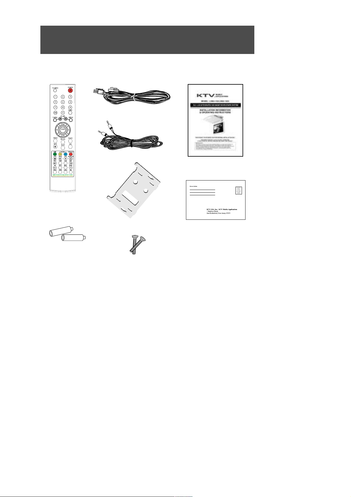
Please check to make sure that all of these items have been included:
Remote Control
R-Link Cable
Batteries (AAA x 2)
Warranty Card
Owner's Manual
Other general and vehicle- specific mounting and installation accessories are also available.
12V DC Power Extension cable
Screw (M4x30) x 2
Mounting Plate
IDENTIFICATION OF
LVMD-102/LVMD-102S
CONTROLS
& CONNECTORS
7
7
1
2
3
4
5
6
12
11
8
1413 1715 16 18
9
10
19
20

IDENTIFICATION OF LVMD-102/LVMD-102S CONTROLS
& CONNECTORS
8
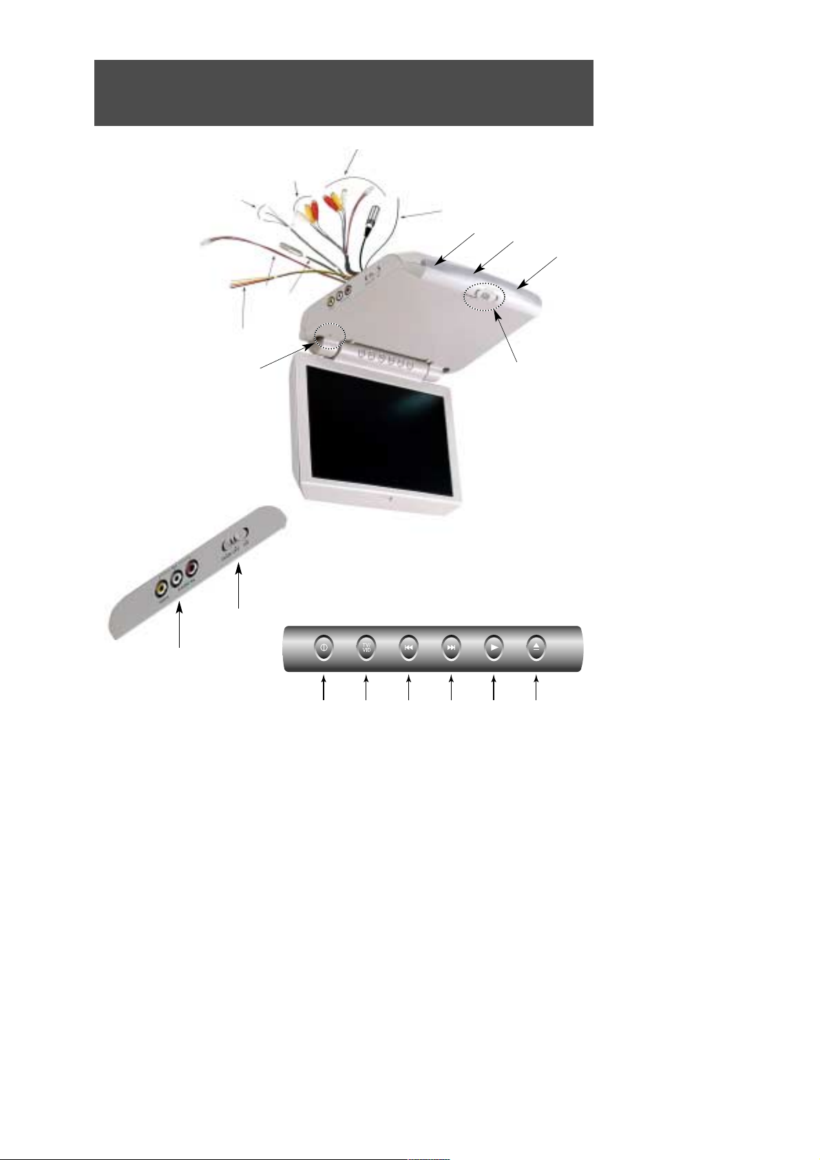
1. DC INPUT JACK
For connection to a source of 12 Volt DC power.
2. EXTERNAL SPEAKERS OUTPUT
CONNECTOR
Supplies 2.0 W/Channel @ 4Ω (variable) for
connection of optional external speakers.
(L+, R+, Common Ground).
3. L&R AUDIO/VIDEO (THROUGH) OUTPUT
JACKS
Supplies L&R Audio and Video signal for
connection to additional monitors, external
amplifiers, etc.
When
the LVMD-102/LVMD-102S is powered
on, these outputs always feed the
signal from the
selected input source.
When the
LVMD-102/LVMD-102S
is powered
off, these outputs always feed the signal from the
program source connected to A/V1.
4. L&R AUDIO/VIDEO 1 INPUT JACKS
For connection of a 1st external program source.
DC OUT JACK
For connection to a supplies of 12 volt DC power.
R-Link JACK
For connection to an external KTV Mobile
Applications VCP or DVD Player.
5. ANTENNA INPUT JACK
For connection of an external television broadcast antenna.
6. DOME LIGHTS POWER CONNECTION
WIRES
Provides power to lamps (Refer to page 15 for
instructions on proper connection of this 4-wire
system).
7. FM TRANSMITTER ANTENNA
Transmits low-power stereo audio signal for
reception on the vehicle's FM Radio.
8. DOME LIGHTS
Provides additional vehicle lighting.
9. REMOTE CONTROL SENSOR
Receives control signals from the remote control
hand unit. Also passes controls signals to an
external KTV Mobile Applications Videocassette
Player or DVD Player that is connected via an RLink cable.
10. LCD PANEL DROP-DOWN BUTTON
Side to release LCD Panel from stored position.
11. L&R AUDIO/VIDEO 2 INPUT JACKS
For connection of a 2nd external program source.
12. DOME LIGHTS SWITCH
Selects lighting mode.
13. POWER BUTTON
Press to power the system ON/OFF.
14. TV/VIDEO BUTTON
Press repeatedly to select the desired program
source: Broadcast TV, DVD, Video 1, Video 2.
15. DVD PREVIOUS BUTTON
Use this button to move to the DVD's previous
chapter.
16. DVD NEXT BUTTON
Use this button to move to the DVD's next
chapter.
17. DVD PLAY BUTTON
Use this button to play a disc.
18. DVD OPEN/CLOSE BUTTON
Used to eject the videocassette or disc.
19. AUTO POWER SWITCH
Lowering LCD Panel automatically turns power
on.
20. STAND-BY INDICATOR
Illuminates to indicate that 12 Volt DC Power is
available, but that LCD screen is not currently
powered on.
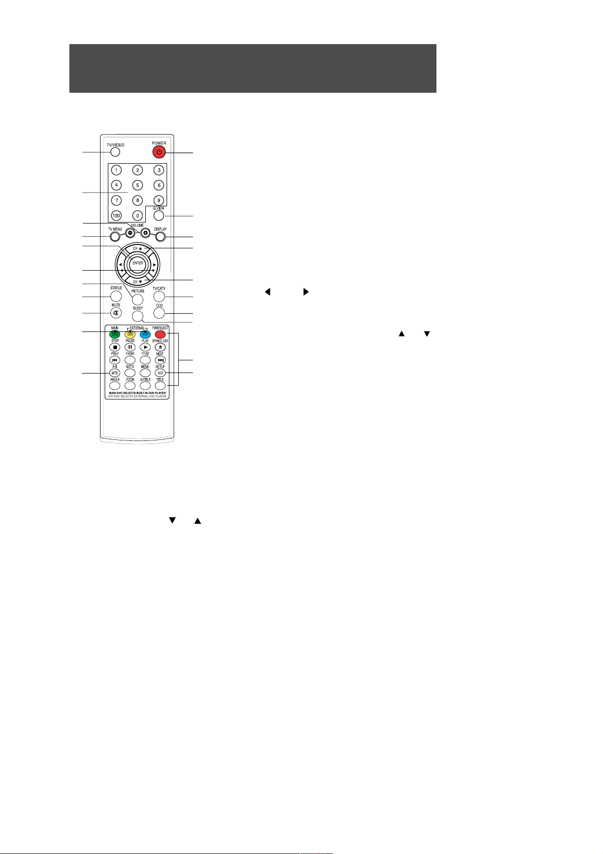
REMOTE CONTROL USE
9
2
4
3
6
8
7
5
9
19
17
1
10
11
12
13
13
14
15
20
18
16
1. TV/VIDEO BUTTON
Press repeatedly to cycle program source selection between
TV, VIDEO, S-VIDEO, YCbCr(Component Video) & PC. This
button is duplicated on the TV's Control Panel.
2. DIRECT CHANNEL SELECTION (0 ~ 9 & 100) BUTTONS
Used for the direct selection of broadcast channels.
3. VOLUME -/+ BUTTONS
These 2 buttons are primarily used in conjunction with the TV
MENU & PICTURE buttons. However, if speakers are connected to the EXTERNAL SPEAKERS OUTPUT, they also work to
adjust volume. These buttons are duplicated on the TV's Control
Panel.
4. TV MENU BUTTON
Press to call up an on-screen menu. Press repeatedly to cycle
through the available menu items and clear the menu from the
screen. This button is duplicated on the TV's Control Panel.
5. ENTER BUTTON
Used in conjuction with Disc and Setup Menus.
6. LEFT / RIGHT BUTTONS
Used to select meu items with some on-screen menus.
The system must not be in TV mode.
7. PICTURE BUTTON
Press to call up the on-screen Picture Menu. Press CH (or CH )
to cycle through Contrast, Brightness, Sharpness, Color, Tint .
The selected item will be displayed in BLUE. Adjust the desired item
with the VOLUME buttons.
8. STATUS BUTTON
Press repeatedly to cycle between a user-adjustable picture and
3 different preset picture balances.
9. MUTE BUTTON
Press to reduce sound to minimum level. Press again to restore.
10. POWER BUTTON
P
ress to turn the LCD Panel ON/OFF. This button is duplicated on
the TV's Control Panel.
11. QUICK VIEW BUTTON
Press to cycle between the current and the previously viewed channel. The system must be in TV mode for this button
to function.
12. DISPLAY BUTTON
Press the display information about the current Program source and SLEEP TIMER setting.
13.CHANNEL DOWN / UP BUTTONS
Press to view the next higher or lower channel stored in memory. Also used to select menu items with some onscreen menus. These buttons are duplicated on the TV's Control Panel.
14.TV/CATV BUTTON
Select regular broadcast television reception or cable broadcast reception. Press repeatedly to cycle between
TV and CATV modes. The system must be in TV mode for this to function.
15. CCD BUTTON
Press repeated to cycle between Closed Captions 1, Closed Captions 2, Text 1, Text 2 and Off.
16. SLEEP BUTTON
Sets the TV to automatically power off in 15-90 minutes.
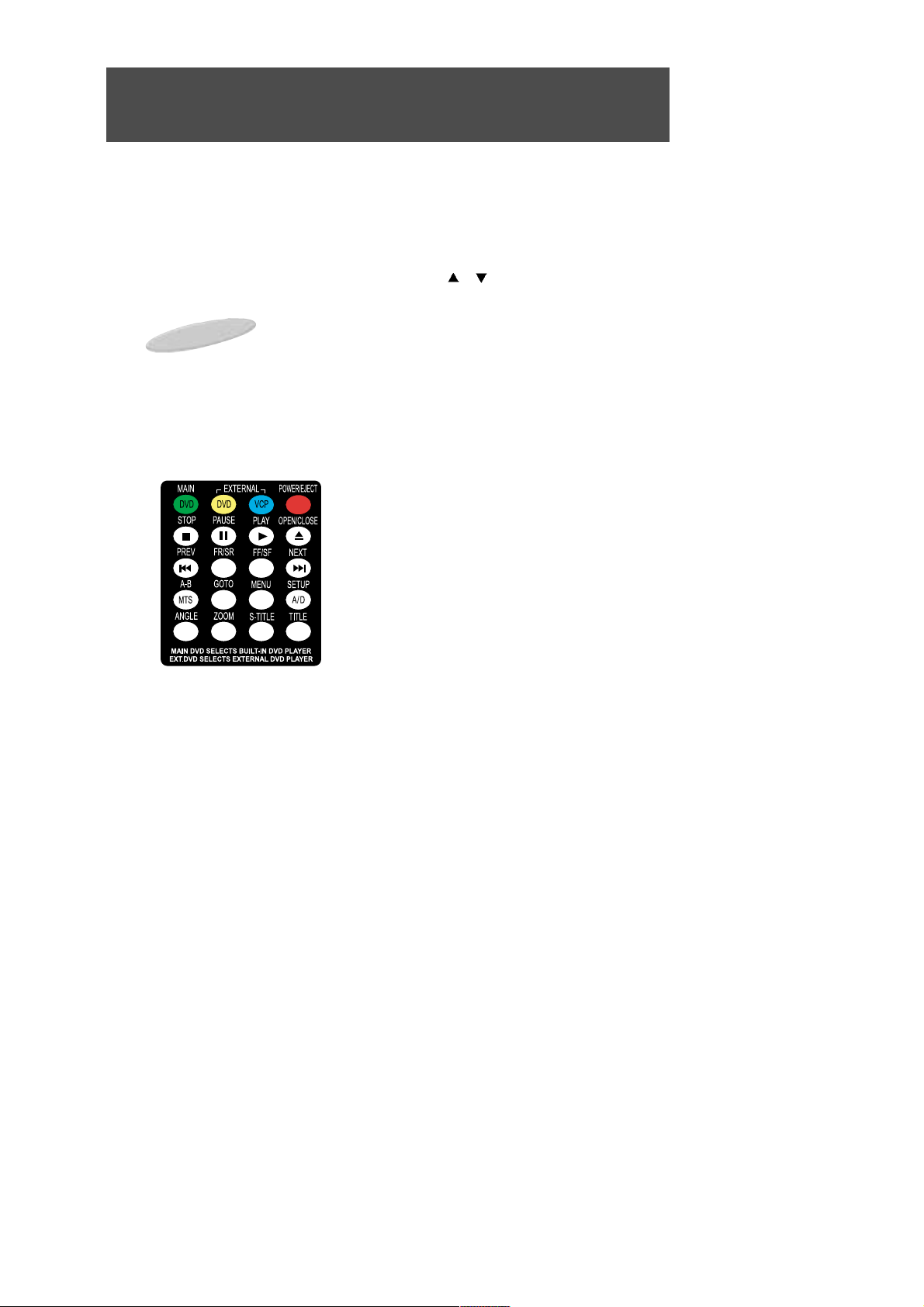
17. MODE TV/DVD/VCP BUTTONS
Press the GREEN MAIN DVD MODE button to control the TV(CH /CH , MTS,A/D).
Press the YELLOW EXTERNAL DVD MODE button to control an EXTERNAL DVD Player.
Press the BLUE EXTERNAL VCP MODE button to control an EXTERNAL Videocassette Player.
18. DVD & VCP CONTROLS
These controls are designed to operate KTV Mobile Applications DVD Players and Videocassette Players ONLY.
Some controls may operate Products from another manufacturer, but operation will be erratic.
STOP: Used to stop the DVD or videotape.
PAUSE: Used to "freeze" the pictre on the DVD or videotape.
PLAY: Used to play a recorded videotape or DVD.
OPEN/CLOSE: Used to eject the videocassette or disc.
PREVIOUS:
Use this button to move to the DVD's previous chapter.
FR/SR: Used to Fast or Slow Reverse the DVD or videotape.
FF/SF: Used to Fast or Slow Forward the DVD or videotape.
NEXT: Use this button to move to the DVD's next chapter.
A-B: Use this button to repeat the selected segment, or for speci-
fying and repeating playback of a segment.
GOTO: Use this button for jumping to a specified location.
MENU: Use this button to display the contents menu of the DVD.
This function is disc dependent. A disc may not contain a contents menu and different discs may have widely differing menus.
STEUP: Use this button to display the LVMD-102/LVMD-102S's built-in setup menus for Language,
Video, Audio and Parental Control.
ANGLE: If a disc includes multi angle information, the user can view screens in multiple angles. This
function is limited to discs which support multi angle information.
ZOOM: Use this button to enlarge the screen image up to 4 times. You may also move around the
image using the ARROW buttons (#6, #13).
S-TITLE: Use this button to change the subtitle language to a different language or from the one
selected at the initial settings. This function is disc dependent. A disc may not contain no subtitles and
different discs will contain differing subtitles.
TITLE : Use this button to display the title menu of the DVD.
19. MTS Button :
Press the cycle between STEREO, SAP, MONO. The system must be in TV mode for this to function.
20. A/D Button :
Press to ADD or REMOVE a channel from the TV's memory. The system must be in TV mode for this to fnction.
REMOTE CONTROL USE
10
Important Notes:
The GREEN MAIN DVD MODE button is used to control the TV.
The YELLOW EXTERNAL DVD button is used to control an EXTERNAL DVD Player.
The BLUE EXTERNAL VCP button is used to control an EXTERNAL VCP.

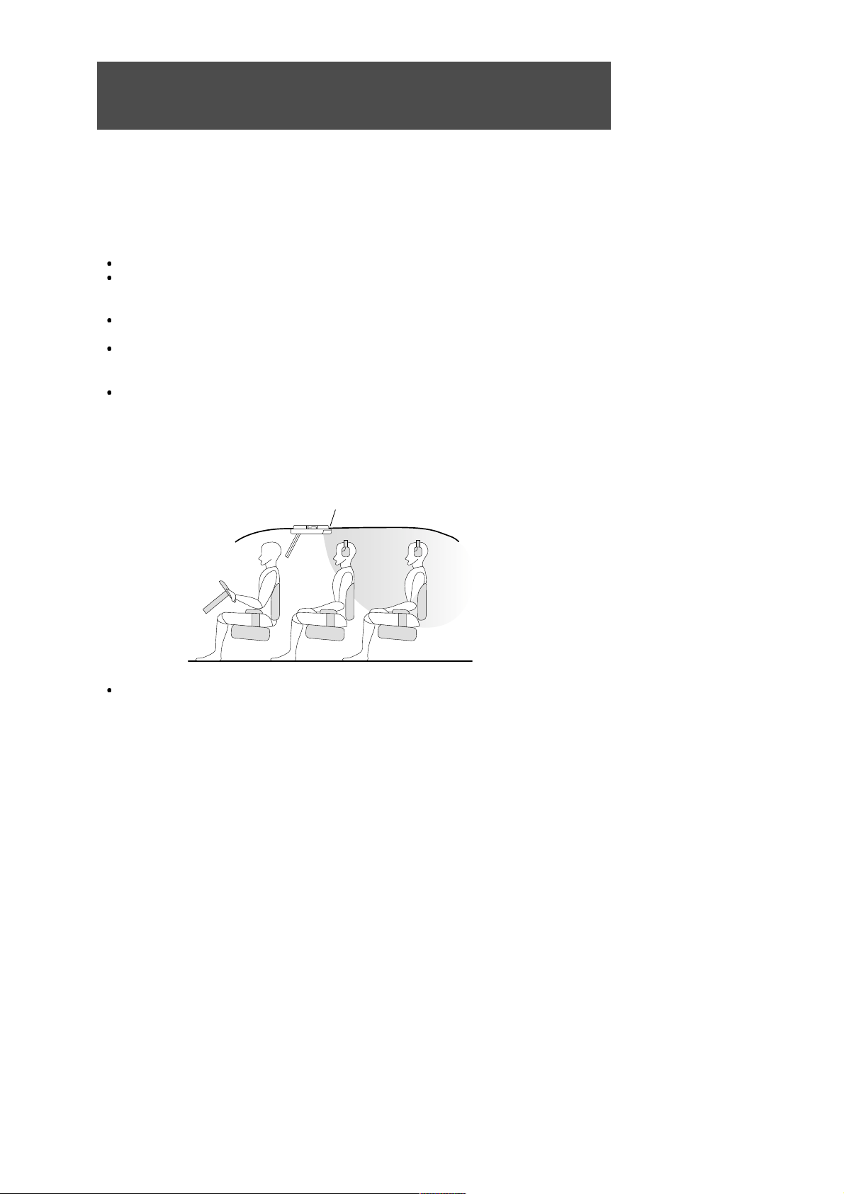
REMOTE CONTROL USE
11
CAUTION : Avoid dropping the remote control.
NOTES :
The Remote control should be directed at the Remote Control sensor just below the LCD
Screen as shown above.
The maximum operating distance of the Remote Control is about 10 feet.
The Remote Control should be kept away from UV exposure which may disrupt its operation.
It may be difficult to receive Remote Control signals when UV is present. If this occurs, it will be
necessary to operate it closer to the Remote Control Sensor.
It is time to replace the batteries when the remote control is not working properly.
( Alkaline batteries usually last for 6 months to 1 year. )
Press battery compartment tab in the direction of the arrow and lift off cover.
Install new batteries in the compartment. Be sure to observe the correct polarity (+/-) as indicated in
the compartment.
Use only new AAA batteries of the same type.
If batteries become exhausted, remove them immediately to avoid leakage.
Should battery leakage occur, clean the battery compartment with a soft cloth and replace with new
batteries.
REMOTE CONTROL BATTERY INSTALLATION
Remote control sensor
30
30

SIGNAL CONNECTION
12
This illustration shows only one possible example of external equipment connection. For a more detailed
understanding of each connection, please refer to the instruction manuals supplied with each component you
plan to connect.
R-LINK
AV-1 INPUT
VHF/UHF
ANTENNA
75-ohm
Coaxial Cable
POWER OUTPUT
12V DC INPUT
AV-OUTPUT
External Speaker
(4 ohms x 2)
AV2 INPUTS
GAME, CAMERA
DVD,ETC.
DOME LIGHTS POWER
CONNECTION WIRES
FM TRANSMITTER
ANTENNA
Be sure to disconnect POWER before making any connections.
Connector Connect To
2-Pin Mate & Lock VCP or DVD 12V Power Input and Output
(Designed to provide power to KTV products ONLY)
RCA Plug Yellow (Male) A/V1 Video Output
RCA Plug Red (Male) A/V1 Right Audio Output
RCA Plug White (Male) A/V1 Left Audio Output
RCA Plug Yellow (Male) A/V1 Video Input
RCA Plug Red (Male) A/V1 Right Audio Input
RCA Plug White (Male) A/V1 Left Audio Input
Mini Phone Plug (Male) VCP R-Link Input/Output
SIGNAL CONNECTION (continued)
13
AUDIO SYSTEM
The Audio Outputs always feed a low-level audio signal from the selected input.
The Audio Outputs feed a Monophonic signal whenever the selected input source has a Monophonic
audio signal (e.g. a monophonic broadcast from the built-in TV Tuner, or the signal from a Monophonic
VCP connected to the VIDEO 1, 2 input terminals).
The Audio Outputs feed a Stereo signal whenever the selected input source has a Stereo audio signal
(e.g. a stereo broadcast received by the built-in TV Tuner, or the signal from the built-in DVD player).
The EXTERNAL SPEAKERS OUTPUT CONNECTOR feeds a high level mono or stereo signal
whose level is Variable up to 1.0W maximum when connected to 4-ohm speakers.
IR (Infrared Rays) Transmitter
The built-in IR Transmitter allows you to listen to the Stereo or Monophonic audio signal from the selected program source (TV, DVD, VIDEO1, VIDEO2) on IR Wireless Headphones compatible with those
that arre manufactured by Unwired Technology LLC. They are widely available under the Unwired brand
name. Headphones sold under other brand names that are compatible with Unwired may also be used.
The IR signal is always live.
Wireless FM Transmitter
The built-in FM Broadcast Transmitter allows you to listen to the Stereo or Monophonic audio signal from the
selected program source (TV, DVD, VIDEO1, VIDEO2) on the FM Band of the vehicle's radio or on headphones equipped with an FM tuner. See page 21 of this manual for a full description and details of operation.
VIDEO SYSTEM
This model incorporates 2 sets of External STEREO AUDIO/VIDEO INPUTS (
VIDEO1, VIDEO2
) for direct connection of up to 2 external program sources (Videocassette Player, Video Game, Camcorder, etc.). Direct connection results in superior video quality and should be used whenever the external program source provides
direct outputs. Refer to the instruction manual supplied with each external instrument for details.
IR TRANSMITTER
TRANSMITTER POSITIONING
SELECTING THE PROGRAM SOURCE
Press the TV/VIDEO button on the Remote Control or LVMD-102/LVMD-102S Control Panel to select
the desired program source. Repeatedly pressing the button will switch between inputs as follows:
Broadcast TV (built-in) DVD VIDEO 1 VIDEO 2 Broadcast TV ......
 Loading...