

KTS-Electronic GPA 500 User Manual

Ground
Penetrating
Analyzer
GPA 500
User’s Manual
KTS 3D
KTS-Electronic GmbH & Co. KG
Germany

KTS-Electronic GmbH & Co. KG – GPA 500
Table of content
1 General guidelines ......................................................................................................... 4
1.1 Preface ................................................................................................................ 4
1.2 Important details ................................................................................................ 4
1.3 Scope of delivery ............................................................................................... 4
2 Hardware operation for GPA 500 .................................................................................. 6
2.1 Assembly of the universal probe ...................................................................... 6
2.2 Electronic Unit .................................................................................................... 7
2.3 Starting the electronic ....................................................................................... 8
3 Start of program ........................................................................................................... 10
3.1 Preadjustment KTS 3 D .................................................................................... 10
3.1.1 Start-button ........................................................................................................ 11
3.1.2 Completion of measurement .............................................................................. 11
3.1.3 Transfer of measurement data ........................................................................... 11
3.1.4 3D presentation .................................................................................................. 11
3.2 Search process (measurements) .................................................................... 12
3.2.1 Search in one direction ....................................................................................... 12
3.2.2 Search in counter direction ................................................................................. 13
4 Program operations ..................................................................................................... 13
4.1 Main window ..................................................................................................... 13
4.1.1 Toolbar ............................................................................................................... 14
4.1.2 Display range ..................................................................................................... 14
4.2 Menu bar ........................................................................................................... 14
4.2.1 Data menu ......................................................................................................... 14
4.2.2 Display menu ..................................................................................................... 14
4.2.3 Options menu ..................................................................................................... 14
4.2.4 Info menu ........................................................................................................... 14
4.3 Options window ............................................................................................... 15
4.3.1 Paths .................................................................................................................. 15
4.3.2 Colors and coordinates ...................................................................................... 15
4.3.3 Languages ......................................................................................................... 16
4.3.4 Serial Interface ................................................................................................... 16
5 Data recordings............................................................................................................ 17
5.1 Modulation before data recording ................................................................... 17
5.1.1 Display during data recording ............................................................................. 17
5.1.2 Display after completion of data recording .......................................................... 18
5.2 Display alternatives .......................................................................................... 18
5.2.1 Proportional or square display ............................................................................ 18
5.2.2 Data presentation - absolute or relative .............................................................. 18
6 Search process ............................................................................................................ 19
6.1 Search with the universal probe ..................................................................... 19
6.2 Live mode ......................................................................................................... 20
6.3 3D-search mode ............................................................................................... 20
6.4 Rechargeable battery and charger .................................................................. 21

KTS-Electronic GmbH & Co. KG – GPA 500
Chapter GOLD ID-XL
7 Electronic Unit ............................................................................................................. 22
7.1 Back side .......................................................................................................... 23
8 Search process ............................................................................................................ 23
8.1 Search recommendations and hints for Reset operation .............................. 24
8.2 Exact location of metal objects ....................................................................... 26
9 Search progress........................................................................................................... 27
9.1 Assembly .......................................................................................................... 27
9.2 Usage and selection of searchcoils ................................................................ 27
9.3 25 cm coil .......................................................................................................... 27
9.4 Cylindrical coil .................................................................................................. 28
9.5 Battery and chargers ....................................................................................... 28
10 Error signals ..................................................................................................... 29
11 Technical data .................................................................................................. 29
12 Driver-reinstalling (only by reinstalling) ......................................................... 30
12.1 Bluetooth pairing ............................................................................................. 30
13 System requirements and license agreement ................................................ 32
13.1 System requirements ....................................................................................... 32
13.2 License agreement ........................................................................................... 32
13.3 Utilization regulations ...................................................................................... 32
13.4 Liability exclusions .......................................................................................... 32
14 Warranty ........................................................................................................... 33
14.1 After expiration date ........................................................................................ 33
14.2 Care ................................................................................................ ................... 33
14.3 Legal note ......................................................................................................... 34
15 Contact .............................................................................................................. 34

KTS-Electronic GmbH & Co. KG – GPA 500
4
1 General guidelines
1.1 Preface
Congratulations on your purchase of the high performance detector GPA 500.
Since programs are already pre-installed, the assembly is quite simple. The
instruction manual is written in plain style and furnished with numerous illustrations,
so that the practicable application will be problem-free.
This instruction has been developed by KTS-Electronic GmbH & Co. KG. Any
alterations or duplications are only allowed with written permission of KTS-Electronic.
KTS-Electronic reserves the right to modify the instruction with new knowledge at
anytime. The new instructions always can be downloaded gratuitously from our
website.
Your KTS-Electronic Team
1.2 Important details
Please note:
Keep dry.
Avoid conducting overhead lines
Do not use cell phones during operation
Do not process measurements during thunderstorms
Accurate operation is only guaranteed with a fully charged battery
For operation or loading use solely the components enclosed or released by KTS.
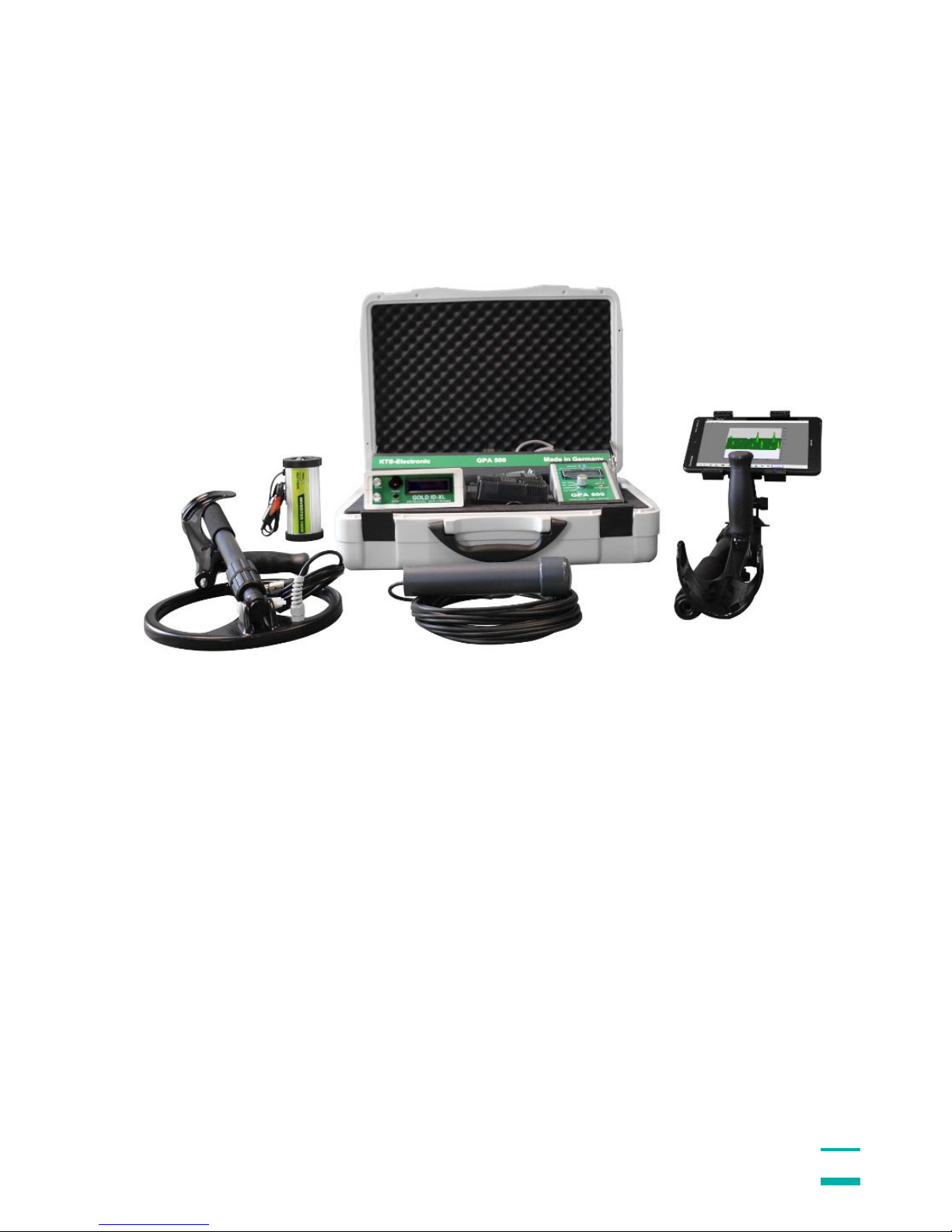
1.3 Scope of delivery
Hardware:
GPA 500 electronic unit with Bluetooth® incl. installed Li-ion battery
GPA Universal probe 48 cm (18“) incl. 2-part carbon telescope bar
Tablet Computer with pre-installed KTS software incl.Li-ion battery and charger
Quick-charger 220 Volt including 110 Volt adapter
Transformer to charge in car
Headphones
Solid hard-top case
Software:
Newly developed KTS-3D software (pre-installed on PC)
USB stick with software for processing data on other computers
KTS-Electronic GmbH & Co. KG – GPA 500
5
Additionally: GOLD ID-XL metal discrimination
GOLD ID-XL electronic unit incl. installed li-ion battery and leather bag
25 cm (10") Ø searchcoil (waterproof) with carbon telescope bar
Cylindrical coil 5 cm Ø (waterproof) with 10 m cable
Powerful quick-charger 220 Volt, inverter with car loading cable and 110 Volt
adapter
Service:
English, German, French or Spanish user's manual
2 years manufacturer's warranty for the entire scope of delivery (incl. hardware
and software)

KTS-Electronic GmbH & Co. KG – GPA 500
6
2 Hardware operation for GPA 500
2.1 Assembly of the universal probe
Plug the bar into probe’s mount. Then insert the remaining parts in correct order. The
universal probe can now be attached to the holder. After that the sensor cable must
be connected. Your device is now ready for operation.
Fig.: Telescope bar
Please do not overwind the thread
Fig.: 4-part demountable universal probe
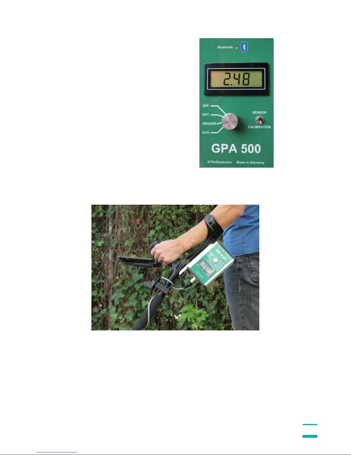
Fig.: Telescope bar with universal probe and tablet
KTS-Electronic GmbH & Co. KG – GPA 500
7
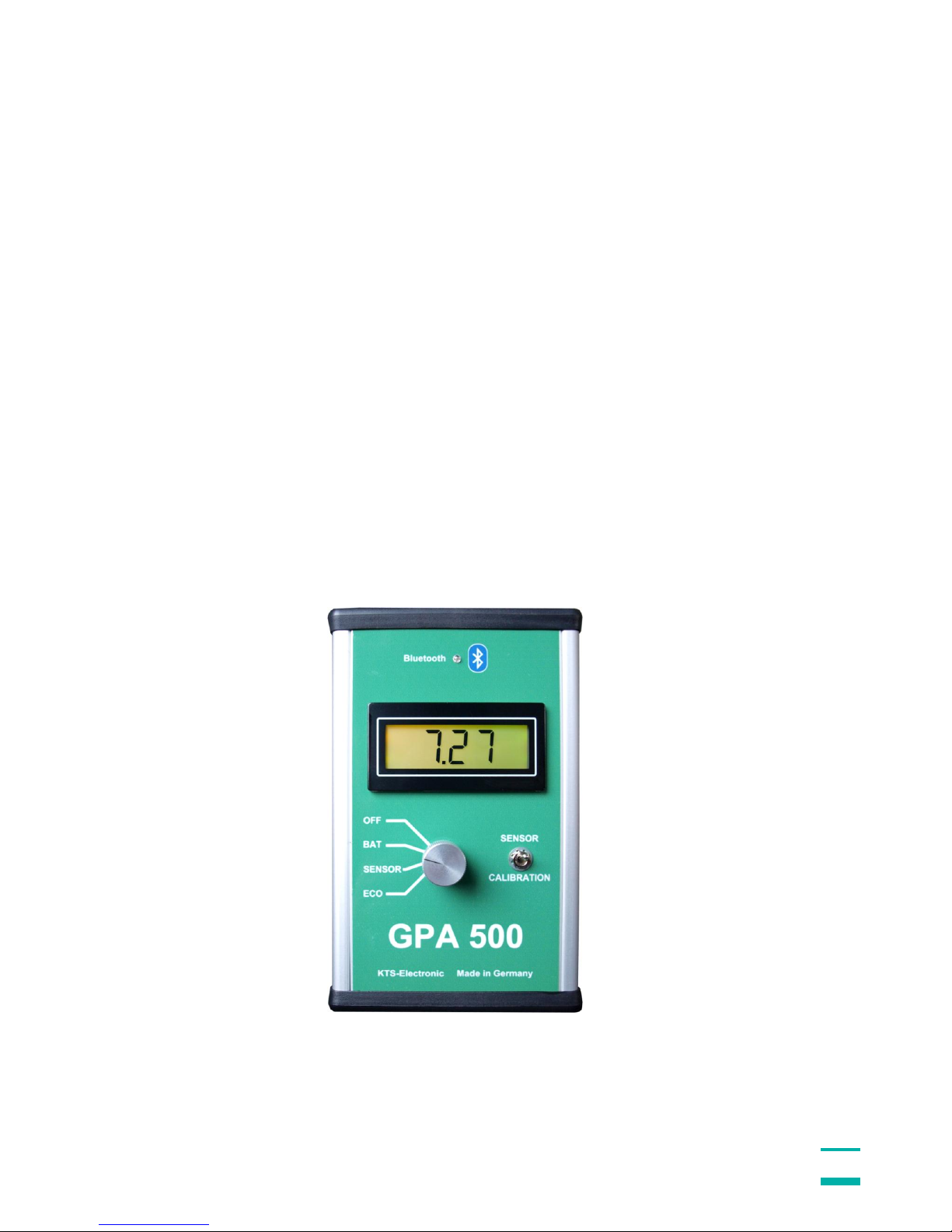
2.2 Electronic Unit
Turn-switch: The rotary control has 4 shift positions:
OFF Device is turned off.
BAT Current battery voltage (should be between 7 and max. 8.2 Volt)
SENSOR Display shows sensor values.
ECO Power save mode, display lighting is not active.
Toggle-switch: SENSOR/CALIBRATION
SENSOR Shows battery voltage (BAT) or current value sensor (SENSOR or ECO).
CALIBRATION Shows calibration value.
The calibration is conducted by a microprocessor and is carried out automatically on
every soil without the necessity of further modulations. The GPA set therefore is
applicable on every soil type.
The measured data is automatically digitized and will be wirelessly transformed to the
tablet computer via Bluetooth. A blue LED flashes after switching on, constant light
signifies the Bluetooth connection.
Fig.: Electronic unit
KTS-Electronic GmbH & Co. KG – GPA 500
8
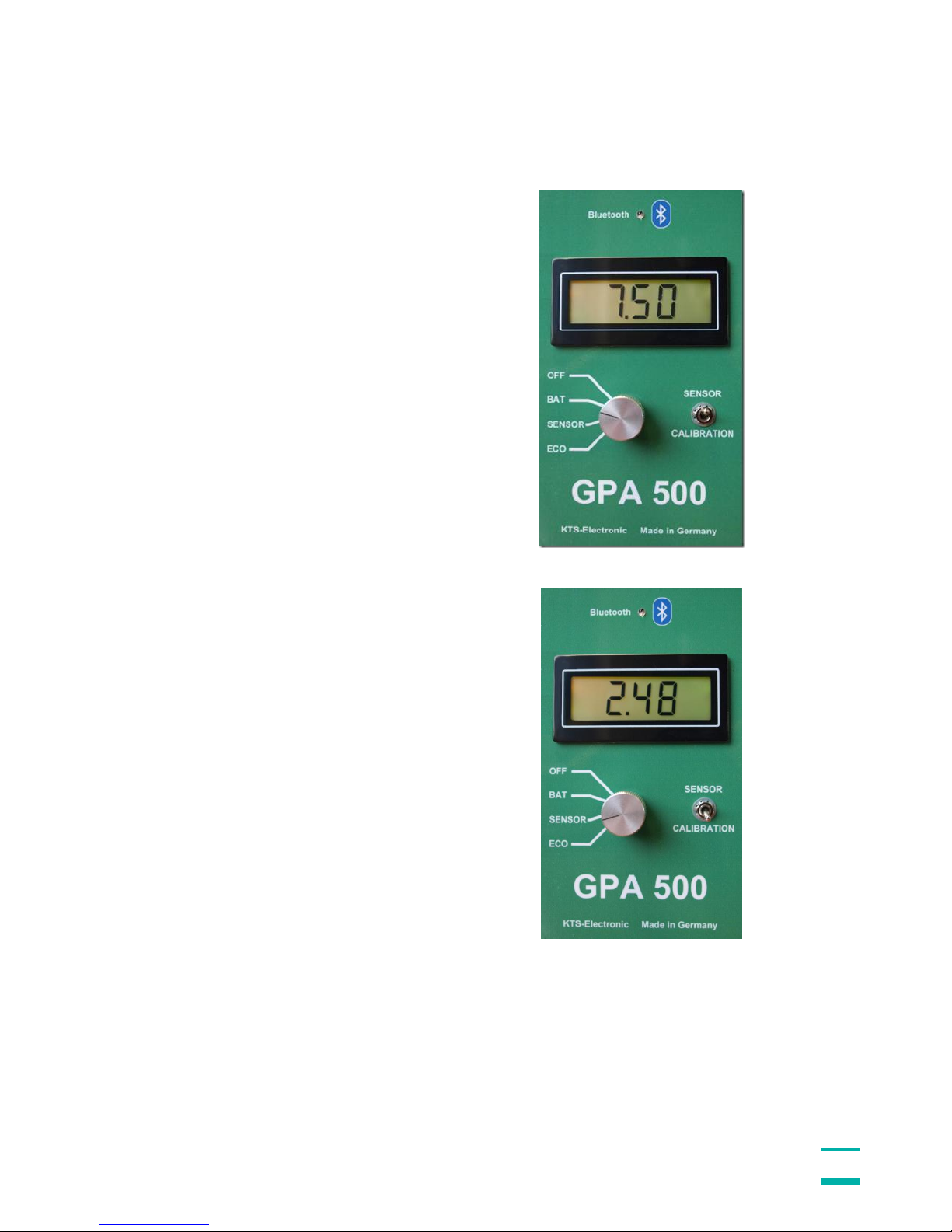
2.3 Starting the electronic
To control the current battery condition
turn the knob to BAT and after that the
toggle switch to SENSOR. The value
must always stand over 7.5 Volt (if not
the case, please charge battery).
Then turn the rotary switch to SENSOR
or ECO to read the sensor or calibration
data. The sensor data should always be
between 1-4 ....
KTS-Electronic GmbH & Co. KG – GPA 500
9
... and CALIBRATION approx. 2.5
(before the calibration automatically is
set it could temporarily show other
values).
KTS-Electronic GmbH & Co. KG – GPA 500
10
3 Start of program
The Bluetooth-connection allows a fast and save transfer of measured data from
GPA 500 to the tablet computer – in contrast to other devices, which record data via
parallel interface.
Boot up the PC and double-click on the KTS-3D icon, then start KTS software. GPA
500 automatically will be connected to the computer (be sure that GPA 500 is
activated before you start KTS 3D-Software). Should the connection not take place,
please see 6.6.
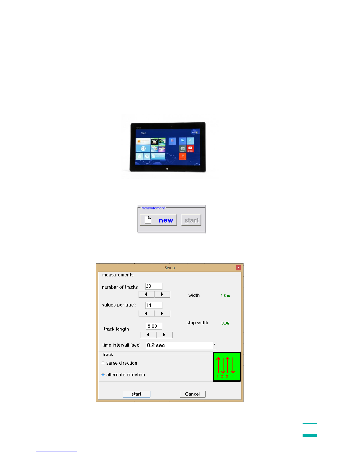
3.1 Preadjustment KTS 3 D
With the "new" button on the display the setting window is opened and
the computer requires the input of track number, track length, values per track and
measurement speed, etc.
KTS-Electronic GmbH & Co. KG – GPA 500
11
3.1.1 Start-button
By pressing the start button the search begins. On screen the results are displayed 2dimensional. After all values are measured, the program stops automatically and is
ready for the next track.
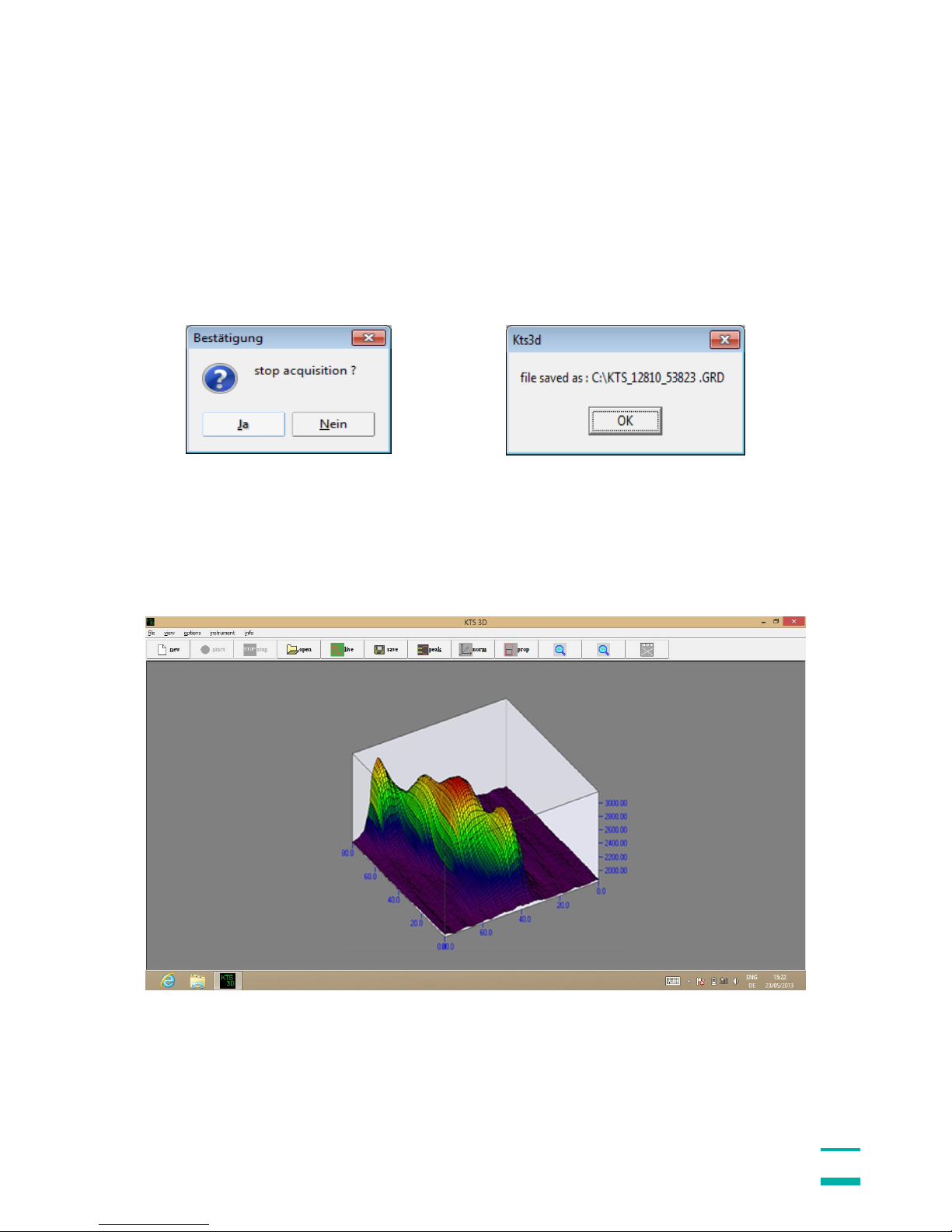
3.1.2 Completion of measurement
After completion of the last track you are going to be asked, if you want to save the
measurements. With the O.K.-button the measurement is stored automatically in a
user-defined file.
3.1.3 Transfer of measurement data
The provided USB-stick can also be used for the transfer of measurement data; you
are able to transmit to other PCs and call up all informations for further processings.
3.1.4 3D presentation
3D presentation shows every modification and its dimension.
 Loading...