

KTS GOLD SCAN 3D User Manual

GOLD SCAN
USERS MANUAL
KTS - 3D Online
KTS - Electronic
Germany
1

Table of contents
1 General hints..................................................................................................................4
1.1 Introduction.........................................................................................................................4
1.2 Delivery contents.................................................................................................................4
1.3 Assembling...........................................................................................................................4
2 Electronic unit...............................................................................................................5
2.1 The front..............................................................................................................................5
2.2 The back...............................................................................................................................6
3 Progress of search.........................................................................................................7
3.1 Principle (important).........................................................................................................7
3.2 The usage of coils.................................................................................................................7
3.2.1 The 45 cm searchcoil.....................................................................................................7
3.2.2 The 1 x 1 m Coil (searchframe)......................................................................................8
3.2.3 General hints to the usage...............................................................................................8
3.3 Precise localisation of metalobjects...................................................................................9
3.4 Hints to the search...............................................................................................................9
3.5 Important hints to the RESET-button............................................................................10
3.6 The search process............................................................................................................10
3.7 Error signals......................................................................................................................11
4 General hints................................................................................................................12
4.1 Search coil choice..............................................................................................................12
4.1.1 45 cm coil.....................................................................................................................12
4.1.2 Cylindric coil................................................................................................................12
4.1.3 1 x 1 m PVC searchframe.............................................................................................12
4.2 Accumulator and charger................................................................................................13
4.3 Care....................................................................................................................................13
4.4 Hint.....................................................................................................................................13
4.5 Locationdepth GOLD SCAN...........................................................................................13
5 Technical data..............................................................................................................14
5.1 Electronic unit...................................................................................................................14
5.2 1 x 1 m coil.........................................................................................................................14
5.3 Computer condition..........................................................................................................14
6 Computer- and programstart....................................................................................14
6.1 Software.............................................................................................................................14
6.1.1 Installing the software...................................................................................................14
6.1.2 Install of virtual Com-Ports ( IMPORTANT ).............................................................14
6.1.3 Port-setup at the computer ( Important ).......................................................................16
6.1.4 Programstart..................................................................................................................21
6.2 Com-Port setup in program.............................................................................................21
6.3 Softwareinformation.........................................................................................................22
7 Driver install (after reinstalling of Windows)..........................................................23
7.1 The search process............................................................................................................23
2

7.1.1 Start-button...................................................................................................................23
7.1.2 Saving the measurement...............................................................................................23
7.1.3 Tranferring the measurement........................................................................................23
7.2 Systemrequirements..........................................................................................................24
7.3 Licence agreement.............................................................................................................24
7.4 Utilisation clauses..............................................................................................................24
7.5 Disclaimer of liability........................................................................................................24
8 Program operations....................................................................................................25
8.1 Main-window.....................................................................................................................25
8.2 Toolbar...............................................................................................................................25
8.2.1 File-menu......................................................................................................................25
8.2.2 Speech...........................................................................................................................25
8.2.3 Info................................................................................................................................25
8.3 Adjustment range..............................................................................................................26
8.3.1 Serial interface..............................................................................................................26
8.3.2 Speed.............................................................................................................................26
8.3.3 Orientation....................................................................................................................26
8.3.4 Start / Stop....................................................................................................................26
8.3.5 Audio output.................................................................................................................27
8.3.6 Scaling..........................................................................................................................27
8.4 Presentation.......................................................................................................................27
9 Warranty......................................................................................................................28
9.1 In period of warranty.......................................................................................................28
9.2 Out period of warranty.....................................................................................................28
10 Contact.........................................................................................................................28
3

1 General hints
1.1 Introduction
Dear customer,
we congratulate you on your purchase of gold scan. The GOLD SCAN is a high tech
product from the company KTS-Electronic. After years of production and
development of various metal detectors, we present you the first metal detector,
which you can directly connect to a PC, to analyze more details of your metal
findings. This informations are very important for gold and treasure hunters,
archaeologists and industry cause finally lost treasures can be recovered.
We pleading you to read this manual carefully, to avoid any errors.
We wish you much success with your new GOLD SCAN, and we are available for
you, if you have more questions.
Your KTS-Electronic Team
1.2 D elivery contents
- GOLD SCAN electronic unit
- USB-Stick with preinstalled software and digital users manual
- 45 cm search coil
- Cylindric coil
- 1x1 m searchframe
- USB-cabel
- leatherbag
- light Stereo-headphone
- Fast-charger
- Carrying case
- English users manual
1.3 Assembling
Compared with other devices, the assembly of your GOLD SCAN is very simple. Only
2 cables must be connected: USB cable and coil cable. And your unit is already
operational.
First, connect the GOLD SCAN electronics unit to the PC through the USB cable,
then connect the coil cable on the back side with the electronics.
4
Important explanation:
The GOLD SCAN is a metaldetector with a connection to a PC with KTS-OnlineSoftware. First you should use this device as a metaldetector, therefor read the
following users manual carefully. Use your GOLD SCAN as a metaldetector, search
and identify your findings on your display (metalclass), then mark the place of
discovery. Later you can scan the marked place of discovery more exact by using
your laptop with your KTS-Online software. The use of laptops and the respective
settings will be explained in the last section.
First the exactly explanation of your device.
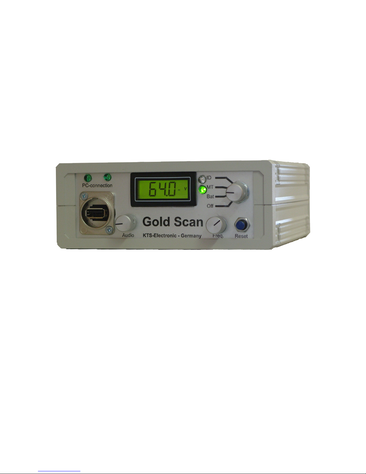
2 Electronic unit
2.1 The front
The electronic unit is in a stable, quality housing. On the front are 4 operating
elements and the digital display.
MODE: The MODE knob can be turned to four different positions:
Off: The device is turned off.
Bat (Battery control): In this position, the device is switched on,
simultaneously the battery charge control can be viewed on the display. The
value must be at full battery to approx 160 or more.
MT (All metal search): In this position all metals will not be tested on their
conductivity, but all metals will be displayed without discrimination, acoustical
and optical through the value number.
This position has the advantage, that you can detect with highest sensibility,
thereby simultaneously a depth measurement happens, that will displayed
through the value number. As smaller the value number, as deeper lies the
metal object. Also about the value number and the sound you can declare
the form.
5

ID (metaldiscrimination): In this position the discriminator will be turned on.
The metal class number of the found metal object will be calculated and
shown on the display. With a little exercise and experience you can declare
the metal class through the shown metal class value. The metal class value
can be between 0-170 depending on the measured metal class.
AUDIO (volume control): With the AUDIO you can regulate the volume.
FREQ. : After the device is switched to the desired position with the MODE knob and
volume was regulated, the frequency should be regulated, that a slow ticking
frequency is perceptible. A fine frequency adjustment is for a stable claytone.
RESET: The RESET button is an automatic zeroing at the push of this button. After
the engage, but before the search starts, the RESET button briefly
must be pushed. After replacing the coil, the RESET button must be pushed
, so that the new coil is set. In addition, the RESET button must be pushed at occur
of a error signal.
LED: In the ID position the conductivity of a metal object will be captured.
Once the ID LED lights and the display value stops at a certain place, the metal class
can be read off. The conductivity value and the ID LED will
as long as shown, until the search coil will be removed from the metal object.
2.2 The back
Socket for coils and charger: The connector for the coil is on the left side. The
connector plug of the search coil will be pluged into the socket. Before removing the
plug, the lever must be pushed, then the plug can be pulled out. The connector is
compatible with all GOLD SCAN search coils. The search coil connector is also the
socket for the charger. To recharge the batteries, insert the plug of the charger
simply into the socket of the coil and controll the loading process. The red LED
shows the recharging process. The green LED shows the end of the recharging
process. Charging with the quick charger takes about 3 to 4 hours,
then the charging plug should be removed.
The connector of the charger should be removed before any storage.
6

Headphone socket: Any commercial headphones with 6.3 mm
jack can be pluged in. If you use the
headphones, the speaker is turned off. A matching, lightweight headphones, is
provided with the device.
3 Progress of search
3.1 Principle (important)
There are two ways of searching:
The scanning of an area
First, you should only search the areal with the metal detector and mark all
possible places of discovery.
The scanning of the place of discovery
Now you can use the software to scan the marked places.
3.2 The usage of coils
3.2.1 The 45 cm searchcoil
The Assembling:
1. Push the lower plastic tube into the middle aluminum tube and connect them with
the upper aluminum tube.
2. Now hold the centerpiece, while with your free hand,
adjusting the mounting-screw in clockwise.
3. Wrap the cable of the search coil around the lower pipe and plug the jack into the
proposed connector on the electronic unit. The electronic untit is in an special
coverbag. The plug should be determined by the lower
opening of the bag to be connected.
The usage:
1. The search coil should be kept about 2 to 5 cm in parallel on the ground level.
2. After switching and regulating the volume and frequency, you should press the
RESET button for balancing the soil.
3. For the soil balance regulatory hold the coil around 5 cm above the ground
(on a metal free position) and press about 3 seconds the RESET button.
With the ground regulatory balance the influence of minerals in the soil will be
neutralised in the search coil, thereby accrue less error signals.
4. Tepeat the ground regulatory balance at various locations, to ensure that the
regulatory is always right accomplished. Especially by change of soil layers, e.g. by
digging out, this process should be repeated.
7
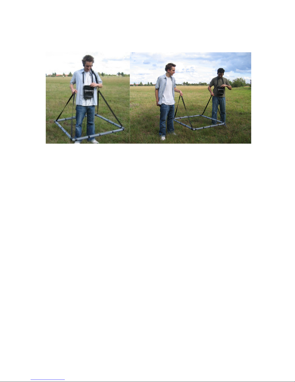
3.2.2 The 1 x 1 m Coil (searchframe)
The assembling:
The 1x1 m search framework is in 2 different versions available.
1. The search cable is in a PVC pipe (8-fold split). In this
case the pipes must be simply put together and with the two
included hanging belts worn.
2. The search cable is not connected to the pipes. in this case, you should first attach
the PVC pipes to the cable with a tape. The advantage is that this variant is easier to
transport.
The usage:
The search framework consists of lightweight plastic pipes and 4-meter cable, that
can be in
or on the pipes attached. It is best suited for the search for greater
objects, shall be used in a wide-area suspects, because with the help of 2
people, you get much faster and more convenient to go. Another advantage of
this large coil is the fact that smaller disturbing metal parts do not will appear. The
search coil can be kept between 20-50 cm above the ground. As higher the distance
to the ground, as lesser can small and medium-sized metal parts be notified.
3.2.3 General hints to the usage
Your GOLD SCAN was designed so that no quickly swing of the search coil
is needed. Just hold down the search probe flat and parallel to the ground, and
you determine your own search speed.
8

After turning on the device, press a brief moment the RESET button and regulate the
FREQ. regulator untill a slow ticking signal is hearable. This signal is acoustically
similar to a second hand. With each new setting press the RESET button to set the
zeroing. With the knob AUDIO set the desired volume.
There are 2 search methods to choose from:
MT. search method:
Thereto set the MODE control to the position MT. This search system, all metals.
With the ALLM. search method you draw more power from your device, but without
metal discrimination.
ID search method:
Thereto set the MODE control to the position ID. This search system uses the metal
discrimination. Once the ID -LED lights and a value will be shown in the display.
Ferrous metals will reach a value up to 120; Aluminium up to 40, about 70 copper
and gold reach a value about 160.
3.3 Precise localisation of metalobjects
Your GOLD SCAN works with the pulse induction searching system and is able to
detect, without setting the search coil in motion. With approximating the search coil to
a
metal object, the frequency of the clay/tone is increased. As soon as the search coil
is
exactly over the object, the highest clay/tone is reached.
With this method the exact place of discovery of the object can be located. By the
clay/tone duration the form of the object can be determined. For example, a long
lasting
high clay/tone stands in longitudinal direction for a narrow object, e.g. a pipe. A high
claytone in any direction indicates a circular object.
3.4 Hints to the search
Please note that you do not carry metal articles with you during the search process.
This could cause a wrong adjustment when pushing the RESET key and can
produce false indicator effects whilst the search process. In addition this can cause a
wrong discrimination or metal distinction.
During the search, make sure that the clay/tone remains constant, otherwise a wrong
adjustment by magnetic fields may occur. Especially with the search
with the 1 x 1 m coil (search framework) be certain that when an instable clay/tone
appears the RESET key is pressed. This must be accomplished in order to prevent
unwanted interferences by geomagnetism.
Strongly magnetized soils affect large search coils (searchframe) more than small
search coils. In the search with the large coil be certain therefore that the search coil
approx. 15-50 cm (depending upon need) is kept parallel to the soil and if possible
without jerky movements.
9
 Loading...