

ROTEX®
Operating/Assembly instructions
KTR-N
Sheet:
Edition:
40210 EN
1 of 22
22
Please observe protection
note ISO 16016.
Drawn:
2017-09-06 Pz/Bru
Replacing:
KTR-N dated 2017-01-02
Verified:
2017-09-06 Pz
Replaced by:
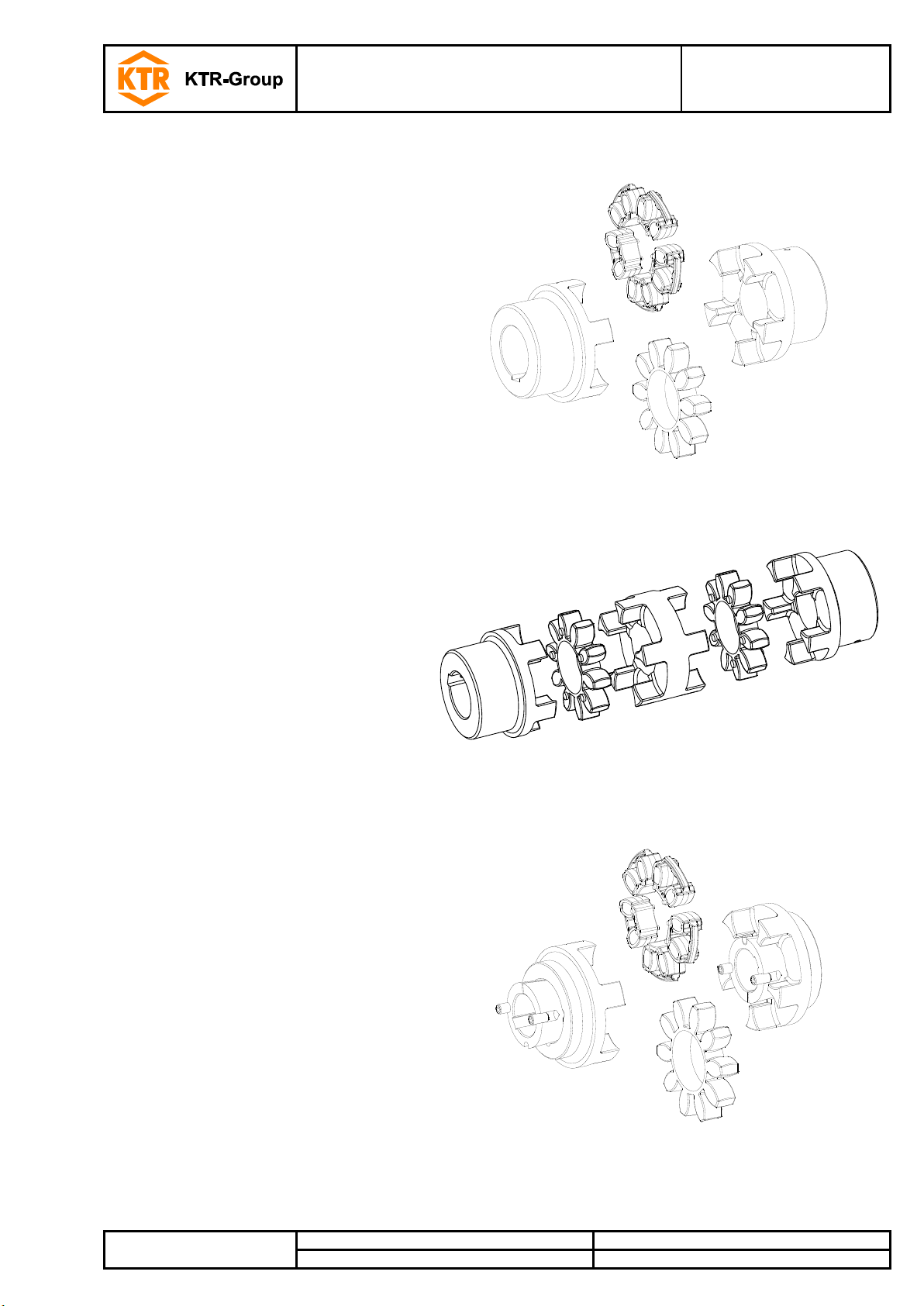
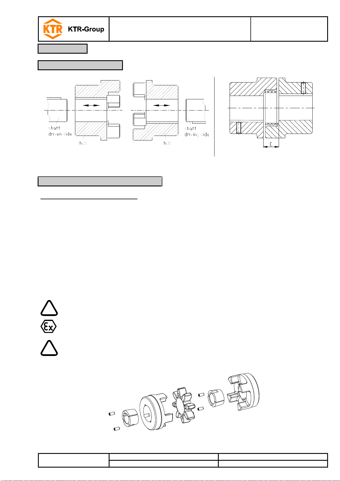
ROTEX®
Torsionally flexible jaw-type couplings
No. 001 – shaft coupling,
No. 018 – DKM,
with taper clamping sleeve
and their combinations
according to directive 2014/34/EU
for finish bored, pilot bored and
unbored couplings
Type No. 001 – shaft coupling
Type No. 018 – DKM
double-cardanic coupling
Type with taper clamping sleeve
ROTEX®
Operating/Assembly instructions
KTR-N
Sheet:
Edition:
40210 EN
2 of 22
22
Please observe protection
note ISO 16016.
Drawn:
2017-09-06 Pz/Bru
Replacing:
KTR-N dated 2017-01-02
Verified:
2017-09-06 Pz
Replaced by:
Table of contents
ROTEX® is a torsionally flexible jaw coupling. It is able to compensate for shaft misalignment, for
example caused by manufacturing inaccuracies, thermal expansion, etc.
1 Technical data 3
2 Advice 5
2.1 General advice 5
2.2 Safety and advice symbols 6
2.3 General hazard warnings 6
2.4 Intended use 6
2.5 Coupling selection 7
2.6 Reference to EC Machinery Directive 2006/42/EC 7
3 Storage, transport and packaging 7
3.1 Storage 7
3.2 Transport and packaging 7
4 Assembly 8
4.1 Components of the coupling 8
4.2 Advice for finish bore 9
4.3 Assembly of the hubs 10
4.4 Assembly of taper clamping sleeve 11
4.5 Displacements - alignment of the couplings 12
5 Start-up 14
6 Breakdowns, causes and elimination 15
7 Disposal 17
8 Maintenance and service 17
9 Spares inventory, customer service addresses 17
10 Enclosure A
Advice and instructions regarding the use in hazardous locations 18
10.1 Intended use in hazardous locations 18
10.2 Inspection intervals for couplings in hazardous locations 19
10.3 Standard values of wear 20
10.4 Permissible coupling materials in hazardous locations 21
10.5 marking of coupling for hazardous locations 21
10.6 EU Certificate of conformity 22
ROTEX®
Operating/Assembly instructions
KTR-N
Sheet:
Edition:
40210 EN
3 of 22
22
Please observe protection
note ISO 16016.
Drawn:
2017-09-06 Pz/Bru
Replacing:
KTR-N dated 2017-01-02
Verified:
2017-09-06 Pz
Replaced by:
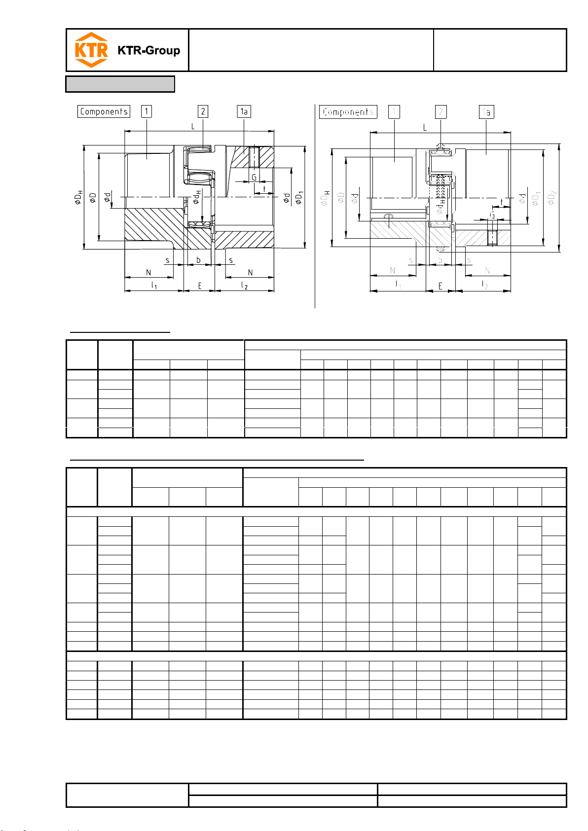
Illustration 1: ROTEX® (material: Al-D)
Illustration 2: ROTEX® (material: EN-GJL-250/EN-GJS-400-15)
Size
Compo
nent
Spider 1) (component 2)
Rated torque [Nm]
Dimensions [mm]
3)
Finish bore 2)
d (min-max)
General
92 ShA
98 ShA
64 ShD
L
l1; l2 E b s DH
DZ
DZ1 4)
dH
D;D1 N 14
1a
7.5
12.5 - 6 - 16
35
11
13
10
1.5
30 - -
10
30
-
19 1 10
17
6 - 19
66
25
16
12
2.0
41 - -
18
32
20
1a
19 - 24
41
24 1 35
60
9 - 24
78
30
18
14
2.0
56 - -
27
40
24
1a
22 - 28
56
28 1 95
160
-
10 - 28
90
35
20
15
2.5
67 - -
30
48
28
1a
28 - 38
67
Size
Compo
nent
Spider 1) (component 2)
Rated torque [Nm]
Dimensions [mm]
3)
Finish bore 2)
d (min-max)
General
92 ShA
98 ShA
64 ShD
L
l1; l2 E b s DH
DZ
DZ1 4)
dH
D;D1
N
Cast iron EN-GJL-250
38 1 190
325
405
12 - 40
114
45
24
18
3.0
80 - -
38
66
37
1a
38 - 48
78
1b
12 - 48
164
70
62
42 1 265
450
560
14 - 45
126
50
26
20
3.0
95 - -
46
75
40
1a
42 - 55
94
1b
14 - 55
176
75
65
48 1 310
525
655
15 - 52
140
56
28
21
3.5
105 - -
51
85
45
1a
48 - 62
104
1b
15 - 62
188
80
69
55 1 410
685
825
20 - 60
160
65
30
22
4.0
120 - -
60
98
52
1a
55 - 74
118
65 1 625
940
1175
22 - 70
185
75
35
26
4.5
135 - -
68
115
61
75 1 1280
1920
2400
30 - 80
210
85
40
30
5.0
160 - -
80
135
69
90 1 2400
3600
4500
40 - 97
245
100
45
34
5.5
200
218
230
100
160
81
Nodular iron EN-GJS-400-15
100 1 3300
4950
6185
50 - 115
270
110
50
38
6.0
225
246
260
113
180
89
110 1 4800
7200
9000
60 - 125
295
120
55
42
6.5
255
276
290
127
200
96
125 1 6650
10000
12500
60 - 145
340
140
60
46
7.0
290
315
330
147
230
112
140 1 8550
12800
16000
60 - 160
375
155
65
50
7.5
320
345
360
165
255
124
160 1 12800
19200
24000
80 - 185
425
175
75
57
9.0
370
400
415
190
290
140
180 1 18650
28000
35000
85 - 200
475
185
85
64
10.5
420
450
465
220
325
156
1 Technical data
Table 1: Material Al-D
Table 2: Material EN-GJL-250 (GG 25)/EN-GJS-400-15 (GGG 40)
1) Maximum torque of the coupling T
2) Bores H7 with keyway to DIN 6885 sheet 1 [JS9] and thread for setscrew
3) For dimensions G and t see table 6; threads for setscrews are located opposite the keyway with material Al-D and on the keyway with
material EN-GJL-250/EN-GJS-400-15
4) DZ1 = internal diameter of housing
= rated torque of the coupling T
Kmax.
K rated
x 2
ROTEX®
Operating/Assembly instructions
KTR-N
Sheet:
Edition:
40210 EN
4 of 22
22
Please observe protection
note ISO 16016.
Drawn:
2017-09-06 Pz/Bru
Replacing:
KTR-N dated 2017-01-02
Verified:
2017-09-06 Pz
Replaced by:
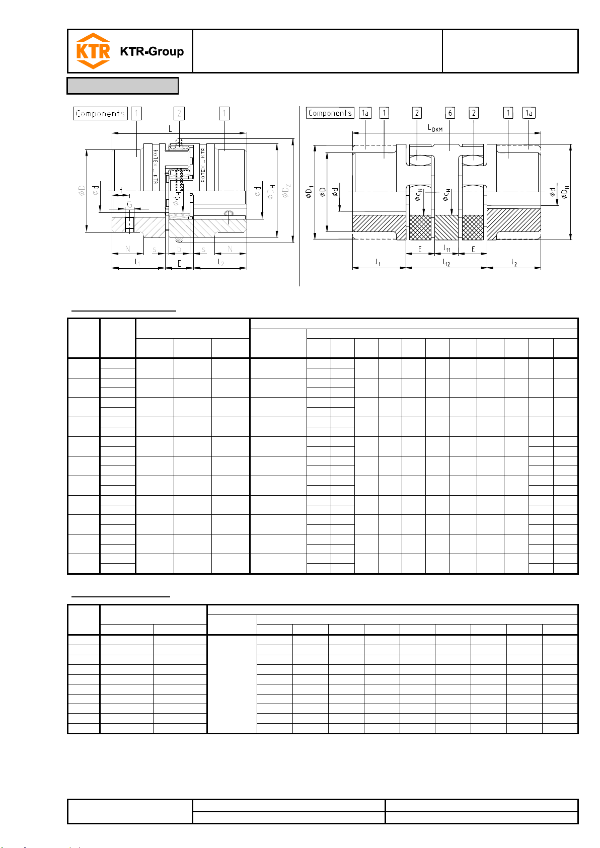
Illustration 3: ROTEX® (material: steel)
Illustration 4: ROTEX®, type DKM 5)
Size
Compo
nent
Spider 1) (component 2)
Rated torque [Nm]
Dimensions [mm]
3)
Finish bore 2)
d (min-max)
General
92 ShA
98 ShA
64 ShD
L
l1; l2 E b s DH
DZ
DZ1 4)
dH D N
14
1a
7.5
12.5
16
0 - 16
35
11
13
10
1.5
30 - -
10
30
1b
50
18.5
19
1a
10
17
21
0 - 25
66
25
16
12
2.0
40 - -
18
40
1b
90
37
24
1a
35
60
75
0 - 35
78
30
18
14
2.0
55 - -
27
55
1b
118
50
28
1a
95
160
200
0 - 40
90
35
20
15
2.5
65 - -
30
65
1b
140
60
38 1 190
325
405
0 - 48
114
45
24
18
3.0
80 - -
38
70
27
1b
164
70
80
-
42 1 265
450
560
0 - 55
126
50
26
20
3.0
95 - -
46
85
28
1b
176
75
95
-
48 1 310
525
655
0 - 62
140
56
28
21
3.5
105 - -
51
95
32
1b
188
80
105
-
55 1 410
685
825
0 - 75
160
65
30
22
4.0
120 - -
60
110
37
1b
210
90
120
-
65 1 625
940
1175
0 - 80
185
75
35
26
4.5
135 - -
68
115
47
1b
235
100
135
-
75 1 1280
1920
2400
0 - 95
210
85
40
30
5.0
160 - -
80
135
53
1b
260
110
160
-
90 1 2400
3600
4500
0 - 110
245
100
45
34
5.5
200
218
230
100
160
62
1b
295
125
200
-
Size
Spider 1) (component 2)
Rated torque [Nm]
Dimensions [mm]
3)
Dimensions
d, D, D1
General
92 ShA
98 ShA
L
DKM
l1; l2 E b s DH
dH
l11
l12
19
10
17
see table 1 to 3
92
25
16
12
2.0
40
18
10
42
24
35
60
112
30
18
14
2.0
55
27
16
52
28
95
160
128
35
20
15
2.5
65
30
18
58
38
190
325
158
45
24
18
3.0
80
38
20
68
42
265
450
174
50
26
20
3.0
95
46
22
74
48
310
525
192
56
28
21
3.5
105
51
24
80
55
410
685
218
65
30
22
4.0
120
60
28
88
65
625
940
252
75
35
26
4.5
135
68
32
102
75
1280
1920
286
85
40
30
5.0
160
80
36
116
90
2400
3600
330
100
45
34
5.5
200
100
40
130
1 Technical data
Table 3: Material steel
Table 4: Type DKM 5)
1) Maximum torque of the coupling T
2) Bores H7 with keyway to DIN 6885 sheet 1 [JS9] and thread for setscrew
3) For dimensions G and t see table 6; threads for setscrews are located opposite the keyway with material Al-D and on the keyway with
material EN-GJL-250/EN-GJS-400-15
4) DZ1 = internal diameter of housing
5) Type DKM not available with DZ elements.
= rated torque of the coupling T
Kmax.
x 2
K rated
ROTEX®
Operating/Assembly instructions
KTR-N
Sheet:
Edition:
40210 EN
5 of 22
22
Please observe protection
note ISO 16016.
Drawn:
2017-09-06 Pz/Bru
Replacing:
KTR-N dated 2017-01-02
Verified:
2017-09-06 Pz
Replaced by:
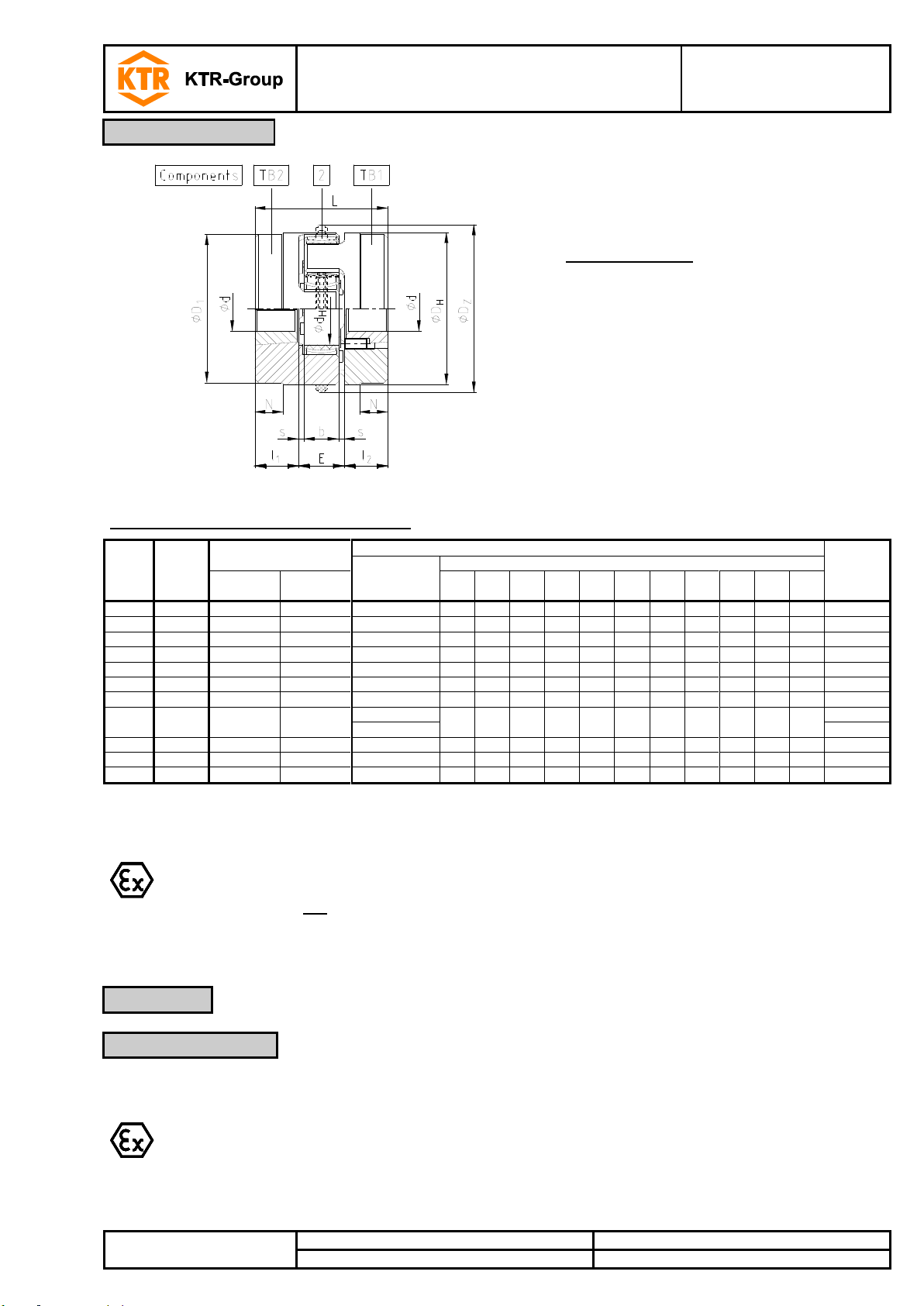
Coupling design:
TB1 Screwing on cam side
TB2 Screwing on collar side
Different combinations of types TB1 and TB2
are possible.
Illustration 5: ROTEX®, type with taper clamping sleeve
Size
Compo
nent
Spider 1) (component 2)
Rated torque [Nm]
Dimensions [mm]
Taper
clamping
sleeve
Finish bore
d (min-max)
General
92 ShA
98 ShA
L
l1; l2 E b s DH
DZ
DZ1
2)
dH
D1
N
24
1a
35
60
10 - 25
64
23
18
14
2.0
55 - -
27 - -
1008
28
1a
95
160
10 - 25
66
23
20
15
2.5
65 - -
30 - -
1108
38
1a
190
325
10 - 25
70
23
24
18
3.0
80 - -
38
78
15
1108
42
1a
265
450
14 - 25
78
26
26
20
3.0
95 - -
46
94
16
1610
48
1a
310
525
14 - 40
106
39
28
21
3.5
105 - -
51
104
28
1615
55
1a
410
685
14 - 50
96
33
30
22
4.0
120 - -
60
118
20
2012
65 1 625
940
14 - 50
101
33
35
26
4.5
135 - -
68
115 5 2012
75 1 1280
1920
16 - 60
144
52
40
30
5.0
160 - -
80
158
36
2517
25 - 75
3020 3)
90 1 2400
3600
25 - 75
149
52
45
34
5.5
200
218
230
100
160
14
3020
100 1 3300
4950
35 - 90
230
90
50
38
6.0
225
246
260
113
180
69
3535
125 1 6650
10000
55 - 110
288
114
60
46
7.0
290
315
330
147
230
86
4545
ROTEX® couplings with attachments that can generate heat, sparks and static charging
(e. g. combinations with brake drums, brake disks, overload systems like torque limiters,
fans etc.) are not permitted for the use in hazardous areas.
A separate analysis must be performed.
The ROTEX® coupling is suitable and approved for the use in hazardous locations. When using the
coupling in hazardous locations, please observe the special advice and instructions regarding safety
in enclosure A.
1 Technical data
2 Advice
2.1 General advice
Table 5: Type with taper clamping sleeve
1) Maximum torque of the coupling T
2) DZ1 = internal diameter of housing
3) Available for type TB2 only
= rated torque of the coupling T
Kmax.
K rated
x 2
Please read through these operating/assembly instructions carefully before you start up the coupling.
Please pay special attention to the safety instructions!
The operating/assembly instructions are part of your product. Please store them carefully and close to the
coupling. The copyright for these operating/assembly instructions remains with KTR.
ROTEX®
Operating/Assembly instructions
KTR-N
Sheet:
Edition:
40210 EN
6 of 22
22
Please observe protection
note ISO 16016.
Drawn:
2017-09-06 Pz/Bru
Replacing:
KTR-N dated 2017-01-02
Verified:
2017-09-06 Pz
Replaced by:
Warning of potentially explosive
atmospheres
This symbol indicates notes which may contribute to
preventing bodily injuries or serious bodily injuries that
may result in death caused by explosion.
STOP
Warning of personal injury
This symbol indicates notes which may contribute to
preventing bodily injuries or serious bodily injuries that
may result in death.
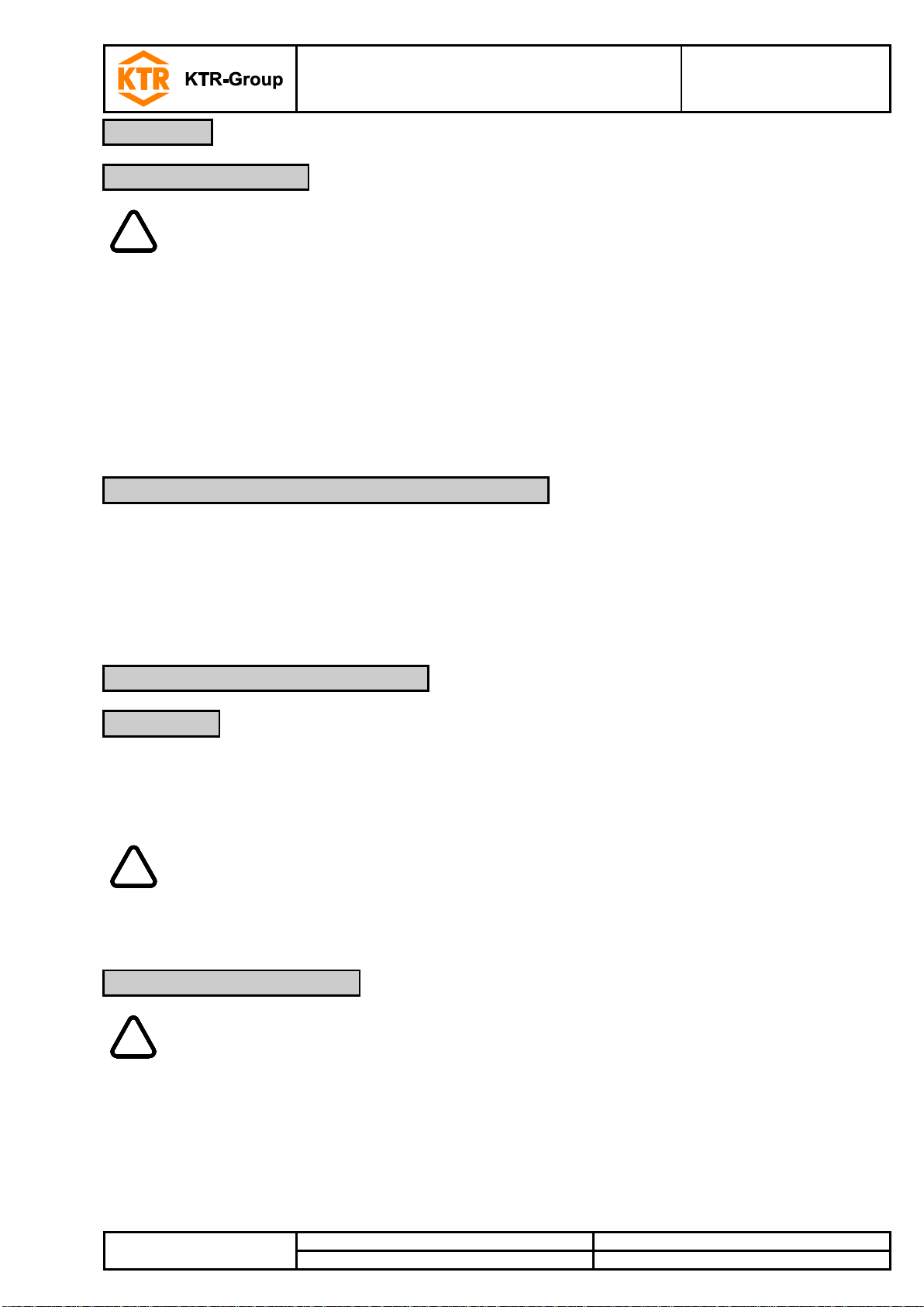
!
Warning of product damages
This symbol indicates notes which may contribute to
preventing material or machine damage.
General advice
This symbol indicates notes which may contribute to
preventing adverse results or conditions.
Warning of hot surfaces
This symbol indicates notes which may contribute to
preventing burns with hot surfaces resulting in light to
serious bodily injuries.
STOP
With assembly, operation and maintenance of the coupling it has to be made sure that the
entire drive train is secured against accidental switch-on. You may be seriously hurt by
rotating parts. Please make absolutely sure to read through and observe the following
safety indications.
2 Advice
2.2 Safety and advice symbols
2.3 General hazard warnings
2.4 Intended use
All operations on and with the coupling have to be performed taking into account "safety first".
Please make sure to switch off the power pack before you perform your work on the coupling.
Secure the power pack against accidental switch-on, e. g. by providing warning signs at the place of switch-on
or removing the fuse for current supply.
Do not reach into the operation area of the coupling as long as it is in operation.
Please secure the coupling against accidental contact. Please provide for the necessary protection devices
and covers.
You may only assemble, operate and maintain the coupling if you
have carefully read through the operating/assembly instructions and understood them
had technical training
are authorized by your company
The coupling may only be used in accordance with the technical data (see chapter 1). Unauthorized modifications
on the coupling design are not admissible. We will not assume liability for any damage that may arise. In the
interest of further development we reserve the right for technical modifications.
The ROTEX® described in here corresponds to the technical status at the time of printing of these
operating/assembly instructions.
ROTEX®
Operating/Assembly instructions
KTR-N
Sheet:
Edition:
40210 EN
7 of 22
22
Please observe protection
note ISO 16016.
Drawn:
2017-09-06 Pz/Bru
Replacing:
KTR-N dated 2017-01-02
Verified:
2017-09-06 Pz
Replaced by:
!
For a permanent and failure-free operation of the coupling it must be selected according to
the selection instructions (according to DIN 740 part 2) for the particular application (see
catalogue drive technology "ROTEX®").
If the operating conditions (performance, speed, modifications on engine and machine)
change, the coupling selection must be reviewed.
Please make sure that the technical data regarding torque refer to the spider only. The
transmittable torque of the shaft-hub-connection must be reviewed by the customer and is
subject to his responsibility.
!
The storage rooms must not include any ozone-generating devices like e. g. fluorescent
light sources, mercury-vapour lamps or electrical high-voltage appliances.
Humid storage rooms are not suitable.
Please make sure that condensation is not generated. The best relative air humidity is less
than 65 %.
!
In order to avoid any injuries and any kind of damage please always make use of proper
transport and lifting equipment.
2 Advice
2.5 Coupling selection
2.6 Reference to EC Machinery Directive 2006/42/EC
3 Storage, transport and packaging
3.1 Storage
3.2 Transport and packaging
For drives subject to torsional vibrations (drives with cyclic stress due to torsional vibrations) it is necessary to
perform a torsional vibration calculation to ensure a reliable selection. Typical drives subject to torsional vibrations
are e. g. drives with diesel engines, piston pumps, piston compressors etc. If requested, KTR will perform the
coupling selection and the torsional vibration calculation.
The couplings supplied by KTR should be considered as components, not machines or partly completed
machines according to EC Machinery Directive 2006/42/EC. Consequently KTR does not have to issue a
declaration of incorporation. For details about safe assembly, start-up and safe operation please refer to the
present operating/assembly instructions considering the warnings.
The coupling hubs are supplied in preserved condition and can be stored at a dry and covered place for 6 - 9
months.
The features of the coupling spiders (elastomers) remain unchanged for up to 5 years with favourable storage
conditions.
The couplings are packed differently each depending on size, number and kind of transport. Unless otherwise
contractually agreed, packaging will follow the in-house packaging specifications of KTR.

ROTEX®
Operating/Assembly instructions
KTR-N
Sheet:
Edition:
40210 EN
8 of 22
22
Please observe protection
note ISO 16016.
Drawn:
2017-09-06 Pz/Bru
Replacing:
KTR-N dated 2017-01-02
Verified:
2017-09-06 Pz
Replaced by:
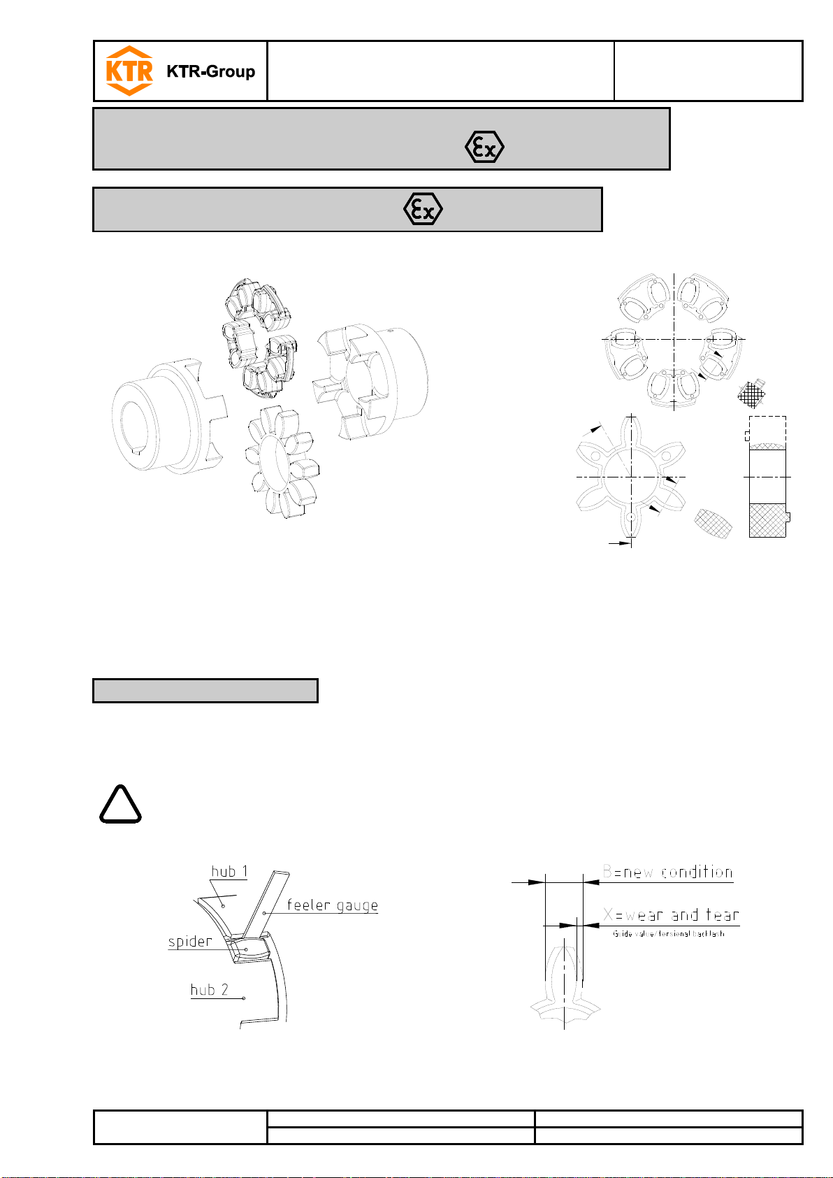
Component
Quantity
Description
Illustration 6: ROTEX®
1
2
Hub 2 1
Spider 1)
3
5 2)
DZ elements 1)
4
2
Setscrews
DIN EN ISO 4029
1) Optionally spider or DZ elements
2) With size 180 the quantity is 6.
Component
Quantity
Description
Illustration 7: ROTEX® DKM
1
2
Hub
2
2
Spider 3 1
DKM spacer
4
2
Setscrews
DIN EN ISO 4029
1) Type DKM not available with DZ elements.
Component
Quantity
Description
Illustration 8: ROTEX® type with taper clamping sleeve
TB1/TB2
2
Hub for taper
clamping sleeve
1
2
Taper clamping
sleeve 2 1
Spider 1)
3
5 2)
DZ elements 1)
4
4
Setscrews
DIN EN ISO 4029
1) Optionally spider or DZ elements
2) With size 180 the quantity is 6.
4 Assembly
4.1 Components of the coupling
The coupling is generally supplied in individual parts. Before assembly the coupling has to be inspected for
completeness.
Components of ROTEX®, shaft coupling type No. 001
Components of ROTEX®, type DKM
1)
Components of ROTEX®, type with taper clamping sleeve
ROTEX®
Operating/Assembly instructions
KTR-N
Sheet:
Edition:
40210 EN
9 of 22
22
Please observe protection
note ISO 16016.
Drawn:
2017-09-06 Pz/Bru
Replacing:
KTR-N dated 2017-01-02
Verified:
2017-09-06 Pz
Replaced by:
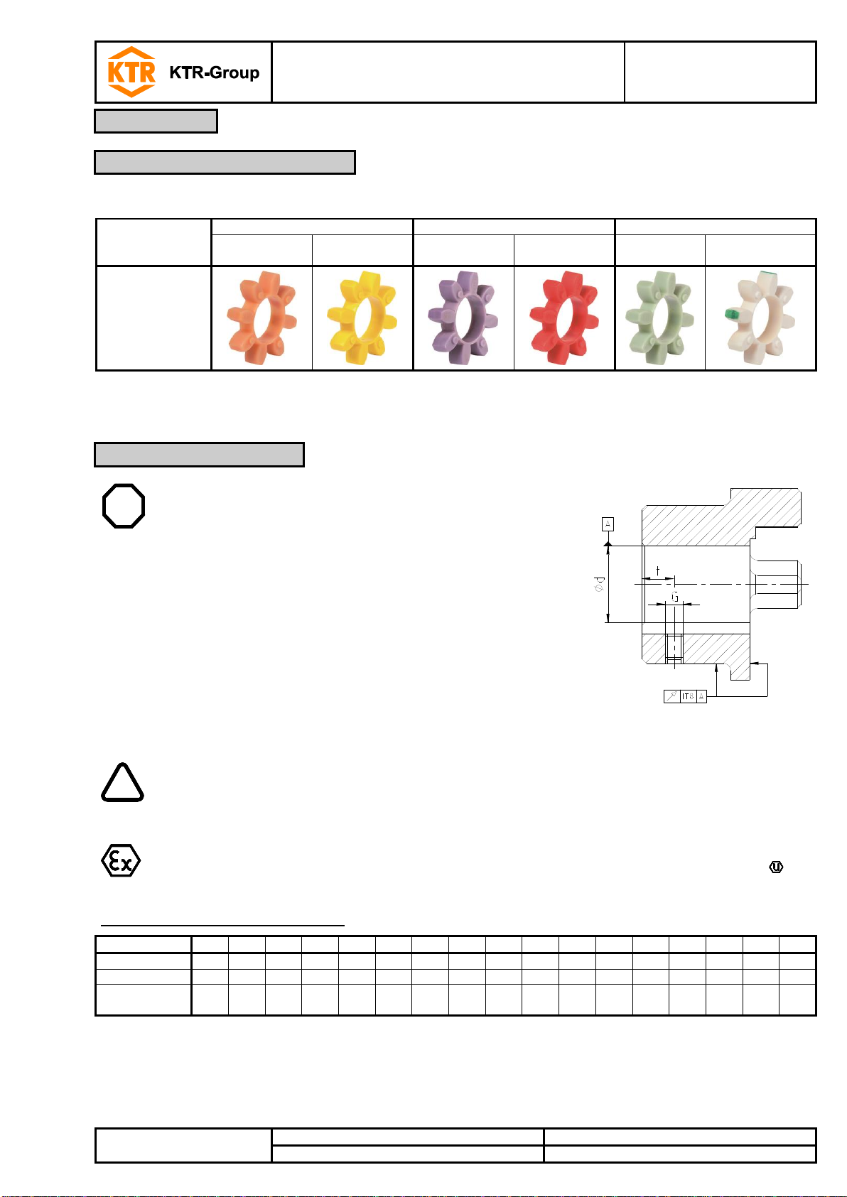
Spider hardness
(Shore)
92 Shore A
95/98 Shore A
64 Shore D
T-PUR®
(orange)
PUR
(yellow)
T-PUR®
(purple)
PUR
(red)
T-PUR®
(light green)
PUR
(natural white 1))
Marking
(colour)
STOP
The maximum permissible bore diameters d (see table 1
to 5 in chapter 1 - technical data) must not be exceeded.
If these figures are disregarded, the coupling may tear.
Rotating particles may cause danger to life.
Hub bores machined by the customer have to observe
concentricity or axial runout, respectively (see illustration
9).
Please make absolutely sure to observe the figures for
Ø d
max
.
Carefully align the hubs when the finish bores are drilled.
Please provide for a setscrew according to
DIN EN ISO 4029 with a cup point or an end plate to fasten
the hubs axially.
Illustration 9: Concentricity and axial runout
!
The customer bears the sole responsibility for all machining processes performed
subsequently on unbored or pilot bored as well as finish machined coupling components
and spare parts. KTR does not assume any warranty claims resulting from insufficient
remachining.
KTR supplies unbored or pilot bored coupling components and spare parts only upon
explicit request of the customer. These parts are additionally labelled with the symbol
.
Size
14
19
24
28
38
42
48
55
65
75
90
100
110
125
140
160
180
Dimension G
M4
M5
M5
M8
M8
M8
M8
M10
M10
M10
M12
M12
M16
M16
M20
M20
M20
Dimension t
5
10
10
15
15
20
20
20
20
25
30
30
35
40
45
50
50
Tightening
torque TA [Nm]
1.5 2 2
10
10
10
10
17
17
17
40
40
80
80
140
140
140
4 Assembly
4.1 Components of the coupling
4.2 Advice for finish bore
Features of standard spiders
1) Natural white with green marking of teeth
Table 6: Setscrews DIN EN ISO 4029

ROTEX®
Operating/Assembly instructions
KTR-N
Sheet:
Edition:
40210 EN
10 of 22
22
Please observe protection
note ISO 16016.
Drawn:
2017-09-06 Pz/Bru
Replacing:
KTR-N dated 2017-01-02
Verified:
2017-09-06 Pz
Replaced by:
Bore [mm]
Shaft tolerance
Bore tolerance
above
up to
50
k6
H7
(KTR standard)
50 m6
We recommend to inspect bores, shaft, keyway and feather key for dimensional accuracy
before assembly.
Heating the hubs lightly (approx. 80 °C) allows for an easier mounting on the shaft.
Please pay attention to the ignition risk in hazardous locations!
STOP
Touching the heated hubs causes burns.
Please wear safety gloves.
!
With the assembly please make sure that the distance dimension E (see table 1 to 5) is
observed to allow for axial clearance of the spider when in operation.
Disregarding this advice may cause damage to the coupling.
If the shaft diameters with inserted feather key are smaller than dimension dH (see table 1
to 5) of the spider, one or two shaft ends may protude into the spider.
If used in hazardous locations the setscrews to fasten the hubs as well as all screw
connections must be secured against working loose additionally, e. g. conglutinating with
Loctite (average strength).
4 Assembly
4.2 Advice for finish bore
4.3 Assembly of the hubs
Table 7: Recommended fit pairs acc. to DIN 748/1
If a feather keyway is intended to be used in the hub, it should correspond to the tolerance ISO JS9 (KTR
standard) with normal operating conditions or ISO P9 with difficult operating conditions (frequently alternating
torsional direction, shock loads, etc.). The keyway should preferably be located between the cams. With axial
fastening by setscrews the tapping should be located on the keyway with the exception of Al-D which should be
located opposite to the keyway.
The transmittable torque of the shaft-hub-connection must be reviewed by the customer and is subject to his
responsibility.
Mount the hubs on the shaft of driving and driven side (see illustration 10).
Insert the spider or DZ elements into the cam section of the hub on the driving or driven side.
Shift the power packs in axial direction until the distance dimension E is achieved (see illustration 11).
If the power packs are already firmly assembled, shifting the hubs axially on the shafts allows for adjusting the
distance dimension E.
Fasten the hubs by tightening the setscrews DIN EN ISO 4029 with a cup point (tightening torques see
table 6).
ROTEX®
Operating/Assembly instructions
KTR-N
Sheet:
Edition:
40210 EN
11 of 22
22
Please observe protection
note ISO 16016.
Drawn:
2017-09-06 Pz/Bru
Replacing:
KTR-N dated 2017-01-02
Verified:
2017-09-06 Pz
Replaced by:
Illustration 10: Assembly of the hubs
Illustration 11: Assembly of coupling
!
If used in hazardous locations the setscrews to fix the taper clamping sleeves have to be
secured against working loose additionally, e. g. conglutinating with Loctite (average
strength).
The use of taper clamping sleeves without a feather key is not permitted in hazardous
locations.
!
Oils and greases with molybdenum disulphide or high-pressure additives, additives of
Teflon and silicone as well as internal lubricants reducing the coefficient of friction
significantly must not be used.
4 Assembly
4.3 Assembly of the hubs
4.4 Assembly of taper clamping sleeve
Assembly of taper clamping sleeve:
Clean the contact surfaces of the taper clamping sleeves and of shaft and hub and afterwards apply thin fluid oil
lightly (e. g. Ballistol Universal oil or Klüber Quietsch-Ex).
The taper clamping sleeves have axially parallel, cylindrical and smooth blind holes. Only half of these holes are
located in the material of the sleeve. The other half located in the hub has threads.
Fit the coupling element and the taper clamping sleeve into each other, make sure that the bores cover each
other and tighten the setscrews lightly. Fit the coupling element along with the taper clamping sleeve on the shaft
and tighten the setscrews at the tightening torque specified in table 8.
During the process of screwing the hub is mounted onto the taper sleeve and thus the sleeve is pressed onto the
shaft. By light blows of the hammer the taper clamping sleeve must be pushed further into the taper bore by
means of a suitable sleeve. Afterwards please re-tighten the setscrews at the tightening torque indicated in table
8. This process must be performed at least once.
After the drive has operated under load for a short while please inspect if the setscrews have unscrewed.
An axial fixing of the Taper Lock hub (coupling hub with taper clamping sleeve) is obtained by proper assembly
only.
Illustration 12: ROTEX®, type with taper clamping sleeve

ROTEX®
Operating/Assembly instructions
KTR-N
Sheet:
Edition:
40210 EN
12 of 22
22
Please observe protection
note ISO 16016.
Drawn:
2017-09-06 Pz/Bru
Replacing:
KTR-N dated 2017-01-02
Verified:
2017-09-06 Pz
Replaced by:
Taper
clamping
sleeve
Screw dimensions
Quantity
Illustration 13: Withworth setscrew (BSW)
G
[inch]
L
[inch]
SW
[mm]
TA
[Nm]
1008
1/4
1/2 3 5.7
2
1108
1/4
1/2 3 5.7
2
1610
3/8
5/8 5 20 2 1615
3/8
5/8 5 20 2 2012
7/16
7/8 6 31 2 2517
1/2
7/8 6 49
2
3020
5/8
1 1/4 8 92
2
3535
1/2
1 1/2
10
115 3 4545
3/4
1 3/4
12
170
3
!
In order to ensure a long service life of the coupling and avoid dangers with the use in
hazardous locations, the shaft ends must be accurately aligned.
Please absolutely observe the displacement figures indicated (see table 9 to 11). If the
figures are exceeded, the coupling will be damaged.
The more accurate the alignment of the coupling, the longer is its service life.
If used in hazardous locations for the explosion group IIC (marking II 2GD c IIC T X), only
half of the displacement figures (see table 9 to 11) are permissible.
Angular displacements
Radial displacements
Axial displacements
Kw = L
1max.
- L
1min.
[mm]
L
max
= L + Ka [mm]
4 Assembly
4.4 Assembly of taper clamping sleeve
4.5 Displacements - alignment of the couplings
Disassembly of taper clamping sleeve:
The taper clamping sleeve is released by removing the setscrews. Afterwards one of the setscrews used as
forcing screw is screwed in the thread of the sleeve and tightened.
The coupling hub detached in this way can be manually removed from the shaft with the taper clamping sleeve.
Table 8:
The displacement figures shown in tables 9 to 11 provide for sufficient safety to compensate for external
influences like, for example, heat expansion or foundation settling.
Please note:
The displacement figures specified in table 9 to 11 are maximum figures which must not arise in parallel. If
radial and angular displacements arise at the same time, the permissible displacement values may only be
used proportionally (see illustration 15).
Please inspect with a dial gauge, ruler or feeler whether the permissible displacement figures of tables 9 to 11
can be observed.
Illustration 14: Displacements

ROTEX®
Operating/Assembly instructions
KTR-N
Sheet:
Edition:
40210 EN
13 of 22
22
Please observe protection
note ISO 16016.
Drawn:
2017-09-06 Pz/Bru
Replacing:
KTR-N dated 2017-01-02
Verified:
2017-09-06 Pz
Replaced by:
Examples of the displacement combinations
specified in illustration 15:
Example 1:
Kr = 30 %
Kw = 70 %
Example 2:
Kr = 60 %
Kw = 40 %
Illustration 15:
Combinations of
displacement
K
total
= Kr + Kw 100 %
Size
14
19
24
28
38
42
48
55
65
75
90
100
110
125
140
160
180
Max. axial displacement Ka
[mm]
-0.5
-0.5
-0.5
-0.7
-0.7
-1.0
-1.0
-1.0
-1.0
-1.5
-1.5
-1.5
-2.0
-2.0
-2.0
-2.5
-3.0
+1.0
+1.2
+1.4
+1.5
+1.8
+2.0
+2.1
+2.2
+2.6
+3.0
+3.4
+3.8
+4.2
+4.6
+5.0
+5.7
+6.4
Max. radial
displacement
Kr [mm] with
1500 rpm
0.17
0.20
0.22
0.25
0.28
0.32
0.36
0.38
0.42
0.48
0.50
0.52
0.55
0.60
0.62
0.64
0.68
3000 rpm
0.11
0.13
0.15
0.17
0.19
0.21
0.25
0.26
0.28
0.32
0.34
0.36
0.38 - - - -
Kw [degree]
max. angular displacement
with n=1500 rpm
Kw [mm]
1.2
1.2
0.9
0.9
1.0
1.0
1.1
1.1
1.2
1.2
1.2
1.2
1.3
1.3
1.2
1.2
1.2
0.67
0.82
0.85
1.05
1.35
1.70
2.00
2.30
2.70
3.30
4.30
4.80
5.60
6.50
6.60
7.60
9.00
Kw [degree]
max. angular displacement
with n=3000 rpm
Kw [mm]
1.1
1.1
0.8
0.8
0.9
0.9
1.0
1.0
1.1
1.1
1.1
1.1
1.2 - - - -
0.60
0.70
0.75
0.85
1.10
1.40
1.60
2.00
2.30
2.90
3.80
4.20
5.00 - - - Size
14
19
24
28
38
42
48
55
65
75
90
100
110
125
140
160
180
Max. axial displacement Ka
[mm]
-0.5
-0.5
-0.5
-0.7
-0.7
-1.0
-1.0
-1.0
-1.0
-1.5
-1.5
-1.5
-2.0
-2.0
-2.0
-2.5
-3.0
+1.0
+1.2
+1.4
+1.5
+1.8
+2.0
+2.1
+2.2
+2.6
+3.0
+3.4
+3.8
+4.2
+4.6
+5.0
+5.7
+6.4
Max. radial
displacement
Kr [mm] with
1500 rpm
0.11
0.13
0.15
0.18
0.21
0.23
0.25
0.27
0.30
0.34
0.36
0.37
0.40
0.43
0.45
0.46
0.49
3000 rpm
0.08
0.09
0.10
0.13
0.15
0.16
0.18
0.19
0.21
0.24
0.25
0.26
0.28 - - - -
Kw [degree]
max. angular displacement
with n=1500 rpm
Kw [mm]
1.1
1.1
0.8
0.8
0.9
0.9
1.0
1.0
1.1
1.1
1.1
1.1
1.2
1.2
1.1
1.1
1.1
0.57
0.77
0.77
0.90
1.25
1.40
1.80
2.00
2.50
3.00
3.80
4.30
5.30
6.00
6.10
7.10
8.00
Kw [degree]
max. angular displacement
with n=3000 rpm
Kw [mm]
1.0
1.0
0.7
0.7
0.8
0.8
0.9
0.9
1.0
1.0
1.0
1.0
1.1 - - - -
0.52
0.70
0.67
0.80
1.00
1.30
1.60
1.80
2.20
2.70
3.50
4.00
4.90 - - - -
Size
19
24
28
38
42
48
55
65
75
90
Max. axial displacement Ka [mm]
+1.2
+1.4
+1.5
+1.8
+2.0
+2.1
+2.2
+2.6
+3.0
+3.4
-1.0
-1.0
-1.4
-1.4
-2.0
-2.0
-2.0
-2.0
-3.0
-3.0
Max. radial displacement
Kr [mm] with n =
1500 rpm
0.45
0.59
0.66
0.77
0.84
0.91
1.01
1.17
1.33
1.48
3000 rpm
0.40
0.53
0.60
0.70
0.75
0.82
0.81
1.05
1.19
1.33
Kw [degree] max. angular
displacement with n =
1500 rpm
1.0
1.0
1.0
1.0
1.0
1.0
1.0
1.0
1.0
1.0
3000 rpm
0.9
0.9
0.9
0.9
0.9
0.9
0.9
0.9
0.9
0.9
4 Assembly
4.5 Displacements - alignment of the couplings
Table 9: Displacement figures for 92 and 95/98 Shore A
Table 10: Displacement figures for 64 Shore D
Table 11: Displacement figures for type DKM only

ROTEX®
Operating/Assembly instructions
KTR-N
Sheet:
Edition:
40210 EN
14 of 22
22
Please observe protection
note ISO 16016.
Drawn:
2017-09-06 Pz/Bru
Replacing:
KTR-N dated 2017-01-02
Verified:
2017-09-06 Pz
Replaced by:
If used in hazardous locations the setscrews to fasten the hubs as well as all screw
connections must be secured against working loose additionally, e. g. conglutinating with
Loctite (average strength).
If the couplings are used in locations subject to dust explosion and in mining the user must
make sure that there is no accumulation of dust in a dangerous volume between the cover
and the coupling. The coupling must not operate in an accumulation of dust.
For covers with unlocked openings on the top face no light metals must be used if the
couplings are used as equipment of equipment group ll (if possible, from stainless steel).
If the couplings are used in mining (equipment group l M2), the cover must not be made of
light metal. In addition, it must be resistant to higher mechanical loads than if it is used as
equipment of equipment group ll.
Openings
Cover [mm]
Top side
Lateral components
Distance „Sr“
Circular - max. diameter
4
8
10
Rectangular - max. lateral length
4
8
10
Straight or curved slot - max. lateral
length/height
not permissible
8
20
!
If you note any irregularities with the coupling during operation, the drive unit must be
switched off immediately. The cause of the breakdown must be specified by means of the
table „Breakdowns“ and, if possible, be eliminated according to the proposals. The potential
breakdowns mentioned can be hints only. To find out the cause all operating factors and
machine components must be considered.
If coated (priming, paintings, etc.) couplings are used in hazardous locations, the requirements on
conductibility and coating thickness must be considered. In case of paintings up to 200 µm
electrostatic load does not have to be expected. Multiple coatings exceeding 200 µm are prohibited
for explosion group llC.
5 Start-up
Before start-up of the coupling, please inspect the tightening of the setscrews in the hubs, the alignment and the
distance dimension E and adjust, if necessary, and also inspect all screw connections for the tightening torques
specified, dependent on the type of coupling.
Finally the coupling protection against accidental contact must be fitted.
The cover must be electrically conductive and included in the equipotential bonding. Bellhousings (magnesium
share below 7.5 %) made of aluminium and damping rings (NBR) can be used as connecting element between
pump and electric motor. The cover may only be taken off with standstill of the unit.
During operation of the coupling, please pay attention to
different operating noise
vibrations occurring.
The minimum distance „Sr“ between the protective device and the rotating parts must at least correspond to the
figures specified below.
If the protective device is used as cover, regular openings can be arranged from the point of view explosion
protection that must not exceed the following dimensions:
Coating of coupling:
ROTEX®
Operating/Assembly instructions
KTR-N
Sheet:
Edition:
40210 EN
15 of 22
22
Please observe protection
note ISO 16016.
Drawn:
2017-09-06 Pz/Bru
Replacing:
KTR-N dated 2017-01-02
Verified:
2017-09-06 Pz
Replaced by:
If used other than intended the coupling can become a source of ignition.
EU directive 2014/34/EU requires special care by the manufacturer and the user.
Breakdowns
Causes
Hazard notes for
hazardous locations
Elimination
Different operating
noise and/or
vibrations occuring
Misalignment
Increased temperature on
the spider surface; ignition
risk by hot surfaces
1) Set the unit out of operation
2) Eliminate the reason for the misalignment
(e. g. loose foundation bolts, breaking of the
engine mount, heat expansion of unit
components, modification of the installation
dimension E of the coupling)
3) For inspection of wear see item inspection
Wear of spider, short-
term torque
transmission due to
metal contact
Ignition risk due to
sparking
1) Set the unit out of operation
2) Disassemble the coupling and remove
remainders of the spider
3) Inspect coupling components and replace
coupling components that are damaged
4) Insert spider, assemble coupling
components
5) Inspect alignment, adjust if necessary
Screws for axial
fastening of hubs
working loose
Ignition risk due to hot
surfaces and sparking
1) Set the unit out of operation
2) Inspect alignment of coupling
3) Tighten the screws to fasten the hubs and
secure against working loose
4) For inspection of wear see item inspection
Breaking of cams
Wear of spider, torque
transmission due to
metal contact
Ignition risk due to
sparking
1) Set the unit out of operation
2) Replace complete coupling
3) Inspect alignment
Breaking of the cams
due to high impact
energy/overload
1) Set the unit out of operation
2) Replace complete coupling
3) Inspect alignment
4) Find out the reason for overload
6 Breakdowns, causes and elimination
The below-mentioned failures can lead to a use of the ROTEX® coupling other than intended. In addition to the
specifications given in these operating and assembly instructions please make sure to avoid such failures.
The errors listed can only be clues to search for the failures. When searching for the failure the adjacent
components must generally be considered.
General failures with use other than intended:
Important data for the coupling selection were not forwarded.
The calculation of the shaft-hub-connection was not considered.
Coupling components with damage occurred during transport are assembled.
If the heated hubs are assembled, the permissible temperature is exceeded.
The clearance of the components to be assembled is not coordinated with one another.
Tightening torques have been fallen below/exceeded.
Components are mixed up by mistake/assembled incorrectly.
A wrong or no spider/DZ elements are inserted in the coupling.
No original KTR components (purchased parts) are used.
Old/ spiders/DZ elements already worn off or spiders/DZ elements stored for too long are used.
: The coupling used/the coupling protection used is not suitable for the operation in hazardous locations
and does not correspond to EU directive 2014/34/EU, respectively.
Maintenance intervals are not observed.
ROTEX®
Operating/Assembly instructions
KTR-N
Sheet:
Edition:
40210 EN
16 of 22
22
Please observe protection
note ISO 16016.
Drawn:
2017-09-06 Pz/Bru
Replacing:
KTR-N dated 2017-01-02
Verified:
2017-09-06 Pz
Replaced by:
Breakdowns
Causes
Hazard notes for
hazardous locations
Elimination
Breaking of cams
Operating parameters
do not meet with the
performance of the
coupling
Ignition risk due to
sparking
1) Set the unit out of operation
2) Review the operating parameters and select
a bigger coupling (consider mounting space)
3) Assemble new coupling size
4) Inspect alignment
Operating error of the
unit
1) Set the unit out of operation
2) Replace complete coupling
3) Inspect alignment
4) Instruct and train the service staff
Early wear of spider
Misalignment
Increased temperature on
the spider surface; ignition
risk by hot surfaces
1) Set the unit out of operation
2) Eliminate the reason for the misalignment
(e. g. loose foundation bolts, breaking of the
engine mount, heat expansion of unit
components, modification of the installation
dimension E of the coupling)
3) For inspection of wear see item inspection
e. g. contact with
aggressive liquids/oils,
ozone influence, too
high/low ambient
temperatures etc.
causing physical
modification of the
spider
Ignition risk due to
sparking with metallic
contact of the cams
1) Set the unit out of operation
2) Disassemble the coupling and remove
remainders of the spider
3) Inspect coupling components and replace
coupling components that are damaged
4) Insert spider, assemble coupling
components
5) Inspect alignment, adjust if necessary
6) Make sure that further physical
modifications of the spider are excluded
Ambient/contact
temperatures which
are too high for the
spider, max.
permissible
e. g. with T-PUR®
T4 = - 50 °C/
+ 120 °C
1) Set the unit out of operation
2) Disassemble the coupling and remove
remainders of the spider
3) Inspect coupling components and replace
coupling components that are damaged
4) Insert spider, assemble coupling
components
5) Inspect alignment, adjust if necessary
6) Inspect and adjust ambient/contact
temperature (possibly corrective by using
different spider materials)
Early wear of spider
(liquefaction of
material inside the
spider cam)
Vibrations of drive
1) Set the unit out of operation
2) Disassemble the coupling and remove
remainders of the spider
3) Inspect coupling components and replace
coupling components that are damaged
4) Insert spider, assemble coupling
components
5) Inspect alignment, adjust if necessary
6) Find out the reason for the vibrations
(possibly corrective by spider with lower or
higher Shore hardness)
If you operate with a worn spider/DZ elements (see item 10.3) and with the subsequent
contact of metal parts a proper operation meeting the explosion protection requirements
and acc. to directive 2014/34/EU is not ensured.
6 Breakdowns, causes and elimination
ROTEX®
Operating/Assembly instructions
KTR-N
Sheet:
Edition:
40210 EN
17 of 22
22
Please observe protection
note ISO 16016.
Drawn:
2017-09-06 Pz/Bru
Replacing:
KTR-N dated 2017-01-02
Verified:
2017-09-06 Pz
Replaced by:
!
Having started up the coupling the tightening torques of the screws have to be inspected
during the usual inspection intervals.
With the use in hazardous locations please observe chapter 10.2 Inspection intervals for
couplings in - hazardous locations.
KTR does not assume any liability or warranty for the use of spare parts and accessories
which are not provided by KTR and for the damages which may incur as a result.
7 Disposal
8 Maintenance and service
9 Spares inventory, customer service addresses
In respect of environmental protection we would ask you to dispose of the packaging or products on termination of
their service life in accordance with the legal regulations and standards that apply, respectively.
Metal
Any metal components have to be cleaned and disposed of by scrap metal.
Nylon materials
Nylon materials have to be collected and disposed of by a waste disposal company.
ROTEX® is a low-maintenance coupling. We recommend to perform a visual inspection on the coupling at least
once a year. Please pay special attention to the condition of the spider of the coupling.
Since the flexible machine bearings of the driving and driven side settle during the course of load, please
inspect the alignment of the coupling and re-align the coupling, if necessary.
The coupling parts have to be inspected for damages.
The screw connections have to be inspected visually.
A basic requirement to ensure the operational readiness of the coupling is a stock of the most important spare
parts on site.
Contact addresses of the KTR partners for spare parts and orders can be obtained from the KTR homepage at
www.ktr.com.
ROTEX®
Operating/Assembly instructions
KTR-N
Sheet:
Edition:
40210 EN
18 of 22
22
Please observe protection
note ISO 16016.
Drawn:
2017-09-06 Pz/Bru
Replacing:
KTR-N dated 2017-01-02
Verified:
2017-09-06 Pz
Replaced by:
Type
Hub design
Sizes
Material
001
Standard
1.0, 1.1, 1.3
1a (large hub)
clamping set 4.1, 4.2, 4.3
38 - 90
Cast iron (GJL)
100 - 180
Nodular iron (GJS)
14 - 180
Steel
Clamping sleeve
Taper clamping sleeve
24 - 125
019
Clamping ring hub
6.0, 6.5
19 - 90
Clamping hub
2.0, 2.1, 2.3
19 - 180
018
DKM
1.0, 1.1
spacers for drop-out center lengths 10
to 40 mm
19 - 90
Hubs, clamping hubs or similar types without feather keyways may be used in category 3
only.
T-PUR®
PUR
Temperature class
Ambient or
operating
temperature Ta
Max. surface
temperature
Temperature class
Ambient or
operating
temperature Ta
Max. surface
temperature
T3, T2, T1
- 50 °C to
+ 120 °C 1)
+ 140 °C 2)
T4, T3, T2, T1
- 30 °C to
+ 90 °C 1)
+ 110 °C 2)
T4
- 50 °C to + 115 °C
+ 135 °C
T5
- 30 °C to + 80 °C
+ 100 °C
T5
- 50 °C to + 80 °C
+ 100 °C
T6
- 30 °C to + 65 °C
+ 85 °C
T6
- 50 °C to + 65 °C
+ 85 °C
10 Enclosure A
Advice and instructions regarding the use in hazardous locations
10.1 Intended use in hazardous locations
ROTEX® DKM and ROTEX® ZS-DKM only with spacer made of steel or aluminium semi-finished products with a
yield point of R
≥ 250 N/mm2.
p0.2
Conditions of operation in hazardous locations
ROTEX® couplings are suitable for the use according to EU directive 2014/34/EU.
1. Industry (with the exception of mining)
Equipment group II of category 2 and 3 (coupling is not approved for equipment group 1)
Media class G (gases, fogs, steams), zone 1 and 2 (coupling is not approved for zone 0)
Media class D (dusts), zone 21 and 22 (coupling is not approved for zone 20)
Explosion group IIC (explosion class IIA and IIB are included in IIC)
Temperature class:
Explanation:
The maximum surface temperatures each result from the maximum permissible ambient or operating temperature Ta plus the maximum
temperature increase T of 20 K which has to be taken into account.
1) The ambient or operating temperature Ta is limited to + 90 °C (valid for T-PUR® only: + 120 °C) due to the permissible permanent
operating temperature of the elastomers used.
2) The maximum surface temperature of + 110 °C (valid for T-PUR® only: + 140 °C) applies for the use in locations which are potentially
subject to dust explosion, too.

ROTEX®
Operating/Assembly instructions
KTR-N
Sheet:
Edition:
40210 EN
19 of 22
22
Please observe protection
note ISO 16016.
Drawn:
2017-09-06 Pz/Bru
Replacing:
KTR-N dated 2017-01-02
Verified:
2017-09-06 Pz
Replaced by:
Explosion group
Inspection intervals
3G
3D
For couplings which are classified in category 3G or 3D the operating and assembly
instructions that are usual for standard operation apply. During the standard operation
which has to be subject to the ignition risk analysis the couplings are free from any ignition
source. Merely the temperature increase produced by self-heating and depending on the
coupling type has to be considered:
for ROTEX®: T = 20 K
II 2GD c IIB
T4, T5, T6
An inspection of the torsional backlash and a visual inspection of the flexible spider/DZ
elements must be performed after 3,000 operating hours for the first time, at the latest after
6 months after start-up of the coupling.
If you note insignificant or no wear on the spider/DZ elements upon this initial inspection,
further inspections can each be performed after 6,000 operating hours or at the latest after
18 months, provided that the operating parameters remain the same.
If you note significant wear during the initial inspection so that it would be recommendable
to replace the spider/DZ elements, please find out the cause according to the table
„Breakdowns“, if possible.
The maintenance intervals must be adjusted to the modified operating parameters without
fail.
II 2GD c IIC
T4, T5, T6
An inspection of the torsional backlash and a visual inspection of the flexible spider/DZ
elements must be performed after 2,000 operating hours for the first time, at the latest after
3 months after start-up of the coupling.
If you note insignificant or no wear on the spider/DZ elements upon this initial inspection,
further inspections can each be performed after 4,000 operating hours or at the latest after
12 months, provided that the operating parameters remain the same.
If you note significant wear during the initial inspection so that it would be recommendable
to replace the spider/DZ elements, please find out the cause according to the table
„Breakdowns“, if possible.
The maintenance intervals must be adjusted to the modified operating parameters without
fail.
Hubs, clamping hubs or similar types without feather keyways may be used in category 3
only.
10 Enclosure A
Advice and instructions regarding the use in hazardous locations
10.1 Intended use in hazardous locations
10.2 Inspection intervals for couplings in hazardous locations
2. Mining
Equipment group I of category M2 (coupling is not approved for equipment group M1).
Permissible ambient temperature - 30 °C to + 90 °C (valid for T-PUR® only: - 50 °C to + 120 °C).
ROTEX®
Operating/Assembly instructions
KTR-N
Sheet:
Edition:
40210 EN
20 of 22
22
Please observe protection
note ISO 16016.
Drawn:
2017-09-06 Pz/Bru
Replacing:
KTR-N dated 2017-01-02
Verified:
2017-09-06 Pz
Replaced by:
Illustration 17.1:
ROTEX® DZ
elements
Illustration 17.2:
ROTEX® spider
Illustration 16: ROTEX® coupling
!
In order to ensure a long service life of the coupling and avoid dangers with the use in
hazardous locations, the shaft ends must be accurately aligned.
Please absolutely observe the displacement figures indicated (see table 9 to 11). If the
figures are exceeded, the coupling will be damaged.
Illustration 18: Inspection of the limit of wear
Illustration 19: Wear of spider
10 Enclosure A
Advice and instructions regarding the use in hazardous locations
10.2 Inspection intervals for couplings in hazardous locations
10.3 Standard values of wear
ROTEX® coupling
Here the backlash between the cams of the coupling and the flexible spider/DZ element must be inspected by
means of a feeler gauge.
When reaching the wear limit maximum friction, the spider/DZ element must be replaced immediately,
irrespective of the inspection intervals.
In case of backlash > X mm, the flexible spider/DZ elements must be replaced.
Reaching the limits for replacing depends on the operating conditions and the existing operating parameters.
ROTEX®
Operating/Assembly instructions
KTR-N
Sheet:
Edition:
40210 EN
21 of 22
22
Please observe protection
note ISO 16016.
Drawn:
2017-09-06 Pz/Bru
Replacing:
KTR-N dated 2017-01-02
Verified:
2017-09-06 Pz
Replaced by:
Size
Limits of wear (friction)
Size
Limits of wear (friction)
X
max.
[mm]
X
max.
[mm]
9 2 65 5 14 2 75 6 19 3 90 8 24 3 100 9 28 3 110 9 38 3 125
10
42 4 140
12
48 4 160
14
55 5 180
14
Short labelling:
(standard)
II 2GD c IIC T X/I M2 c X
Complete labelling:
(valid for T-PUR® only)
II 2G c IIC T6, T5, T4 resp. T3 - 50 °C Ta + 65 °C, + 80 °C,
+ 115 °C resp. + 120 °C
II 2D c T 140 °C/I M2 c - 50 °C Ta + 120 °C
Complete labelling:
(valid for PUR only)
II 2G c IIC T6, T5 resp. T4 - 30 °C Ta + 65 °C, + 80 °C resp.
+ 90 °C
II 2D c T 110 °C/I M2 c - 30 °C Ta + 90 °C
10 Enclosure A
Advice and instructions regarding the use in hazardous locations
10.3 Standard values of wear
10.4 Permissible coupling materials in hazardous locations
10.5 marking of coupling for hazardous locations
Table 12:
In the explosion groups IIA, IIB and IIC the following materials may be combined:
EN-GJL-250 (GG 25)
EN-GJS-400-15 (GGG 40)
Steel
Stainless steel
Semi-finished products of aluminium with a magnesium share of up to 7.5°% and a yield point of
R
≥ 250 N/mm2 are permitted for the use in hazardous locations.
p0.2
Aluminium diecast is generally excluded for hazardous locations.
Couplings for the use in hazardous locations are marked on at least one component completely and on the
remaining components by an label on the outside diameter of the hub or on the front side each for the
operating conditions permitted. The flexible spider or DZ element is excluded. For reason of limited space only the
symbol is stamped up to size 19.
The labelling with explosion group llC includes the explosion groups llA and llB.
If the symbol was stamped in addition to
KTR.
, the coupling component was supplied unbored or pilot bored by
ROTEX®
Operating/Assembly instructions
KTR-N
Sheet:
Edition:
40210 EN
22 of 22
22
Please observe protection
note ISO 16016.
Drawn:
2017-09-06 Pz/Bru
Replacing:
KTR-N dated 2017-01-02
Verified:
2017-09-06 Pz
Replaced by:
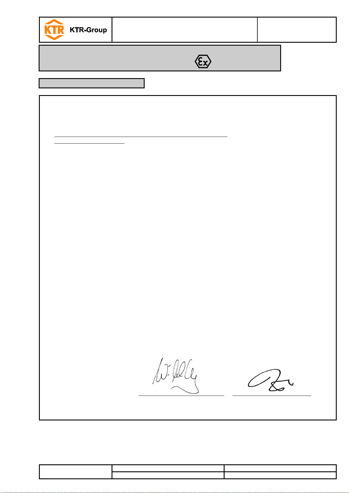
EU Certificate of conformity
corresponding to EU directive 2014/34/EU dated 26 February 2014
and to the legal regulations
The manufacturer - KTR Systems GmbH, D-48432 Rheine - states that the
flexible ROTEX® couplings
in an explosion-proof design described in these operating/assembly instructions are devices
corresponding to article 2, 1. of directive 2014/34/EU and comply with the general safety and health
requirements according to enclosure II of directive 2014/34/EU.
The coupling described in here complies with the specifications of the following standards/guidelines:
DIN EN 1127-1
DIN EN 1127-2
DIN EN 13463-1
DIN EN 13463-5
CLC/TR 50404
The ROTEX® is in accordance with the specifications of the directive 2014/34/EU. One or several
directives mentioned in the corresponding type examination certificate IBExU13ATEXB016 X were in
part replaced by updated versions.
KTR Systems GmbH being the manufacturer confirms that the product mentioned above is in
accordance with the specifications of the new directives, too.
According to article 13 (1) b) ii) of directive 2014/34/EU the technical documentation is deposited with
the institution:
IBExU
Institut für Sicherheitstechnik GmbH
Fuchsmühlenweg 7
09599 Freiberg
Rheine,
2017-01-02
i. V.
i. V.
Place
Date
Reinhard Wibbeling
Engineering/R&D
Michael Brüning
Product Manager
10 Enclosure A
Advice and instructions regarding the use in hazardous locations
10.6 EU Certificate of conformity
 Loading...