

Page 1
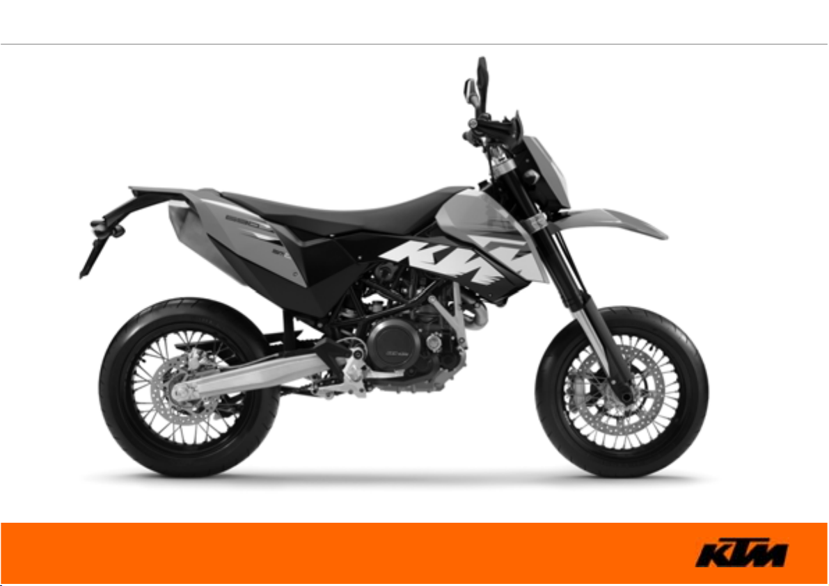
OWNER'S MANUAL 2008
690bSMCbEU
690bSMCbAUS/UK
ART. NO. 3211245en
Page 2

Page 3
DEAR KTM CUSTOMER 1
'($5.70 &86720(5
Congratulations on your decision to purchase a KTM motorcycle. You are now the owner of a state-of-the-art sports motorcycle that will
give you enormous pleasure if you service and maintain it accordingly.
We wish you great pleasure riding the vehicle!
Enter the serial numbers of your vehicle below.
Chassis number ( P. 16) Dealer's stamp
Engine number ( P. 17)
Key number ( P. 17)
The owner's manual corresponded to the latest state of this series at the time of printing. However, it is never possible to exclude small
deviations arising from further development in design and construction.
All specifications are non-binding. KTM Sportmotorcycle AG in particular reserves the right to modify or delete technical specifications,
prices, colors, forms, materials, services, designs, equipment, etc., without prior notice and without specifying reasons, to adapt these to
local conditions, as well as to stop production of a particular model without prior notice. KTM accepts no liability for delivery options, deviations from illustrations and descriptions, as well as misprints and other errors. The models portrayed may contain special equipment that
does not belong to the regular scope of delivery.
Page 4
DEAR KTM CUSTOMER 2
© 2008 by KTM-Sportmotorcycle AG, Mattighofen Austria
All rights reserved
Reproduction, even in part, is permitted only with the express written permission of the copyright owner.
ISO 9001(12 100 6061)
Within the meaning of the international quality management standard ISO 9001, KTM uses quality assurance processes that
lead to the maximum possible quality of the products.
Issued by: TÜV Management Service
KTM-Sportmotorcycle AG
5230 Mattighofen, Austria
Page 5
CONTENTS 3
&217(176
MEANS OF REPRESENTATION ............................................... 7
IMPORTANT NOTES ............................................................... 8
VIEW OF VEHICLE................................................................ 12
View of vehicle, front left side............................................ 12
View of vehicle, rear right side ........................................... 14
LOCATION OF SERIAL NUMBERS ......................................... 16
Chassis number................................................................ 16
Type label........................................................................ 16
Key number ..................................................................... 17
Engine number................................................................. 17
Fork part number.............................................................. 18
Shock absorber part number.............................................. 18
OPERATING ELEMENTS ....................................................... 19
Clutch lever ..................................................................... 19
Hand brake lever .............................................................. 19
Light switch ..................................................................... 20
Light switch ..................................................................... 20
Headlight flasher switch.................................................... 21
Flasher switch .................................................................. 21
Flasher switch .................................................................. 22
Horn ............................................................................... 22
Horn ............................................................................... 23
Emergency OFF switch...................................................... 23
Electric starter button ....................................................... 24
Ignition/steering lock ........................................................ 24
Combination instrument .................................................... 25
Combination instrument - function buttons ......................... 25
Combination instrument - tachometer................................. 26
Combination instrument - control lamps ............................. 26
Combination instrument - Display ...................................... 27
Combination instrument - speed display ............................. 28
Setting kilometers or miles ................................................ 28
Combination instrument - time .......................................... 29
Setting the clock .............................................................. 29
Combination instrument -bODO display ............................... 30
Combination instrument - setting/resettingbTRIPb1 display .... 30
Combination instrument - setting/resettingbTRIPb2 display .... 31
Combination instrument -bTRIPbF display ............................ 32
Combination instrument - coolant temperature indicator ...... 32
Opening filler cap ............................................................. 33
Closing filler cap .............................................................. 33
Handrails......................................................................... 34
Seat release ..................................................................... 34
Passenger footrests ........................................................... 35
Shift lever........................................................................ 35
Foot brake pedal .............................................................. 36
Side stand ....................................................................... 37
GENERAL TIPS AND HINTS ON PUTTING INTO
OPERATION......................................................................... 38
Advice on first use ............................................................ 38
Running in the engine....................................................... 39
Loading the vehicle .......................................................... 40
RIDING INSTRUCTIONS ....................................................... 42
Checks before putting into operation .................................. 42
Starting ........................................................................... 43
Starting up ...................................................................... 45
Shifting, riding ................................................................. 45
Braking ........................................................................... 48
Page 6
CONTENTS 4
Stopping, parking ............................................................. 49
Refueling......................................................................... 51
GREASING AND SERVICE TABLE .......................................... 53
Important maintenance work to be carried out by an
authorized KTM workshop. ................................................ 53
Important maintenance work to be carried out by an
authorized KTM workshop. (as additional order)................... 55
MAINTENANCE WORK ON CHASSIS AND ENGINE ................. 56
Jacking up front of motorcycle ........................................... 56
Taking front from work stand ............................................. 56
Jacking up rear of motorcycle ............................................ 57
Take the rear from the work stand. ..................................... 57
Fork/shock absorber .......................................................... 58
Adjusting compression damping of fork .............................. 58
Adjusting rebound damping of fork..................................... 59
Compression damping of shock absorber............................. 60
Adjusting the low-speed compression damping of the shock
absorber .......................................................................... 60
Adjusting high-speed compression damping of the shock
absorber .......................................................................... 61
Adjusting rebound damping of the shock absorber ............... 63
Bleeding fork legs............................................................. 63
Cleaning dust boots of fork legs ......................................... 64
Removing the fork protector............................................... 65
Installing the fork protector ............................................... 66
Checking play of steering head bearingb
Adjusting play of steering head bearingb
Handlebar position ........................................................... 68
Adjusting handlebar positionb
x ........................................ 69
x .......................... 66
x.......................... 67
Adjusting the handlebar angleb
Checking chain dirt .......................................................... 70
Cleaning the chain............................................................ 70
Checking the chain tension ............................................... 71
Adjusting chain tension..................................................... 72
Checking rear sprocket / engine sprocket for wear ................ 74
Checking chain wear ......................................................... 75
Adjusting chain guideb
Checking brake discs ........................................................ 76
Adjusting basic position of handbrake lever......................... 77
Checking front brake fluid level.......................................... 78
Adding brake fluid for front brakeb
Brake linings.................................................................... 80
Checking the front brake linings......................................... 81
Changing the front brake liningsb
Removing front brake liningsb
Mounting front brake liningsb
Checking free play of foot brake lever ................................. 86
Adjusting basic position of foot brake pedalb
Checking rear brake fluid level........................................... 87
Topping up brake fluid of rear brakeb
Checking the rear brake linings .......................................... 90
Changing rear brake liningsb
Removing front wheelb
Installing the front wheelb
Removing rear wheelb
Installing the rear wheelb
Checking the rear hub rubber dampersb
x .................................................. 76
x .................................................. 93
x.................................................... 96
x....................................... 70
x.................................. 78
x.................................... 81
x ........................................ 83
x ......................................... 84
x ................... 86
x.............................. 88
x .......................................... 90
x.............................................. 95
x ............................................... 97
x .......................... 99
Page 7
CONTENTS 5
Tire condition checking ................................................... 100
Checking spoke tension................................................... 101
Checking tire air pressure................................................ 102
Removing the seat .......................................................... 103
Mounting the seat .......................................................... 103
Removing the batteryb
Installing the batteryb
Recharging the batteryb
Changing the main fuse .................................................. 107
Changing fuses of individual power consumers .................. 109
Adjusting the engine characteristic................................... 111
Removing headlight mask with headlight .......................... 113
Refitting the headlight mask with the headlight................. 114
Changing the headlight bulb............................................ 115
Changing the parking light bulb ....................................... 116
Changing the flasher bulb ............................................... 117
Checking headlamp setting.............................................. 118
Adjusting the headlight range .......................................... 119
Removing the air filterb
Installing the air filterb
Cooling system ............................................................... 121
Checking the antifreeze and coolant level ......................... 122
Checking the coolant level............................................... 124
Draining coolantb
Filling the cooling systemb
Adjusting basic position of clutch lever............................. 129
Checking/correcting fluid level of hydraulic clutch ............. 129
Checking play in gas Bowden cable .................................. 130
Adjusting play in gas Bowden cableb
x ................................................. 104
x.................................................. 105
x ............................................... 105
x ............................................... 119
x ................................................ 120
x ........................................................ 126
x ........................................... 127
x............................. 131
Checking engine oil level................................................. 132
Changing engine oil and oil filter, cleaning oil
screensb
Draining engine oilb
Removing the oil filterb
Mounting oil filterb
Cleaning oil screensb
Filling up with engine oilb
Topping up engine oil ..................................................... 139
TROUBLESHOOTING.......................................................... 140
FLASHING CODE ............................................................... 143
CLEANING......................................................................... 146
Cleaning motorcycle ....................................................... 146
CONSERVATION FOR WINTER OPERATION ......................... 148
Conservation for winter operation ..................................... 148
STORAGE .......................................................................... 149
Storage.......................................................................... 149
Putting into operation after storage .................................. 150
TECHNICAL DATA - ENGINE ............................................... 151
Capacity - engine oil ....................................................... 152
Capacity - coolant........................................................... 152
TECHNICAL DATA - ENGINE TIGHTENING TORQUES ........... 153
TECHNICAL DATA - CHASSIS ............................................. 156
Lighting equipment ........................................................ 157
Capacity - fuel................................................................ 158
TECHNICAL DATA - FORK................................................... 159
TECHNICAL DATA - SHOCK ABSORBER .............................. 160
TECHNICAL DATA - CHASSIS TIGHTENING TORQUES ......... 162
SUBSTANCES.................................................................... 165
x..................................................................... 132
x .................................................... 133
x................................................ 134
x...................................................... 136
x................................................... 136
x ............................................ 138
Page 8
CONTENTS 6
AUXILIARY SUBSTANCES................................................... 168
STANDARDS...................................................................... 170
INDEX ............................................................................... 171
Page 9
MEANS OF REPRESENTATION 7
0($162)5(35(6(17$7,21
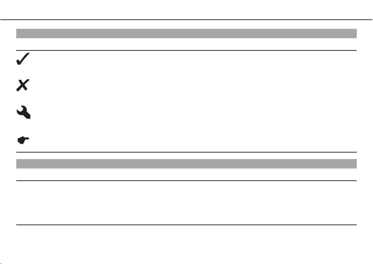
Symbols used
The symbols used are explained in the following.
Indicates an expected reaction (e.g. of a work step or a function).
Indicates an unexpected reaction (e.g. of a work step or a function).
All work marked with this symbol requires specialist knowledge and technical understanding. In the interest of your
own safety, have these jobs done in an authorized KTM workshop! There, your motorcycle will be serviced optimally
by specially trained experts using the specialist tools required.
Identifies a page reference (more information is provided on the specified page).
Formats used
The typographical and other formats used are explained in the following.
Eigenname Indicates a proprietary name.
®
Name
Marke™ Identifies a brand in merchandise traffic.
Identifies a protected name.
Page 10
IMPORTANT NOTES 8
,03257$17127(6
Use definition
KTM sport motorcycles are designed and constructed to meet the normal demands of regular road operation but not for use on race
courses or offroad.
Info
The motorcycle is authorized for public road traffic in the homologous version only.
Maintenance
A prerequisite for perfect operation and prevention of wear is that the engine and chassis maintenance and adjustment work described in
the owner's manual are properly carried out. Poor adjustment and tuning of the engine and chassis can lead to damage and breakage of
components.
Using the motorcycle in extreme conditions such as very muddy or wet roads can lead to above-average wear of components such as the
transmission train or the brakes. For this reason, it may be necessary to service or replace worn parts before the limit specified in the
greasing and service table is reached.
Pay careful attention to the prescribed running-in period, inspection and maintenance intervals. If you observe these exactly, you will
ensure a much longer service life for your motorcycle.
Warranty
The maintenance work prescribed in the greasing and service table must be carried out in an authorized KTM workshop and confirmed in
the customer's service record, since otherwise no warranty claims will be recognized. No warranty claims can be considered for damage
resulting from manipulations and/or alterations to the vehicle.
Fuel, oils, etc.
You should use the fuels, oils and greases according to specifications as listed in the owner's manual.
Page 11
IMPORTANT NOTES 9
Spare parts, accessories
For your own safety, use only spare parts and accessories approved by KTM, and have these mounted only in an authorized KTM workshop.
KTM accepts no liability for other products and any resulting damage or loss.
The currentbKTMbPowerParts for your vehicle can be found on the KTM website.
International KTM Website: http://www.ktm.com
Transport
Note
Danger of damageಘDanger of damage by the vehicle running away or falling over.
ದ Always place the vehicle on a firm and even surface.
Note
Fire hazardಘSome components (engine, radiator and exhaust system) get very hot when the engine is running.
ದ Do not place the vehicle where there are flammable or explosive substances.
ದ Switch off the engine and remove the ignition key.
ದ Use straps or other suitable devices to secure the motorcycle against accidents or falling over.
Environment
Offroad motorcycling is a wonderful sport and we naturally hope that you will be able to enjoy it to the fullest. However, it is a potential
problem for the environment and can lead to conflicts with other persons. But if you use your motorcycle responsibly, you can ensure that
such problems and conflicts do not have to occur. To protect the future of motorcycle sport, make sure that you use your motorcycle
legally, display environmental consciousness, and respect the rights of others.
Page 12
IMPORTANT NOTES 10
Notes/warning notes
Pay attention to the specified notes and warnings.
Info
Various notes and warning labels are attached to the vehicle. Do not remove any notes or warning labels. If they are missing, you or
others may not recognize dangers and may therefore be injured.
Grades of risks
Danger
Danger that leads immediately and certainly to severe and permanent injury or death.
Warning
Danger that will probably lead to severe and permanent injury or death.
Caution
Danger that could possibly lead to slight injuries.
Note
Danger of serious damage to machine or material.
Warning
Risk of environmental damage.
OWNER'S MANUAL
ದ Read this owner's manual carefully and completely before making your first trip. It contains a lot of information and tips to help you
operate and handle your motorcycle. Only then will you find out how to customize the motorcycle ideally for your own use and how you
can protect yourself from injury. The owner's manual also contains important information on servicing the motorcycle.
Page 13

IMPORTANT NOTES 11
ದ The owner's manual is an important component of the motorcycle and should be handed over to the new owner if the vehicle is sold.
Page 14
VIEW OF VEHICLE 12
9,(:2)9(+,&/(
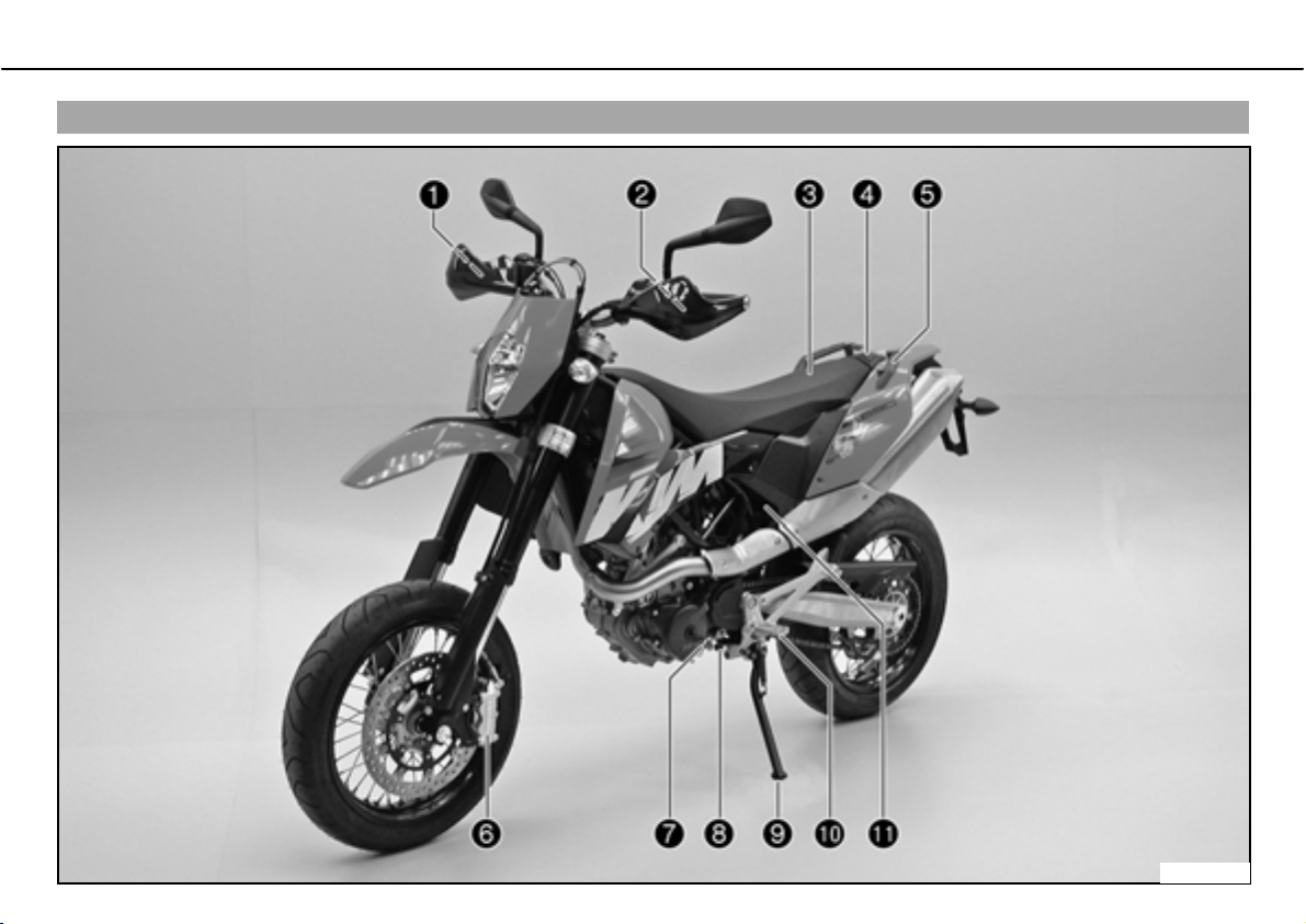
View of vehicle, front left side
600637-10
Page 15

VIEW OF VEHICLE 13
1 Hand brake lever
2 Clutch lever
3 Seat
4 Filler cap
5 Handrail
6 Front brake caliper
7 Shift lever
8 Engine number
9 Side stand
10 Footrest
11 Seat release strap
Page 16
VIEW OF VEHICLE 14
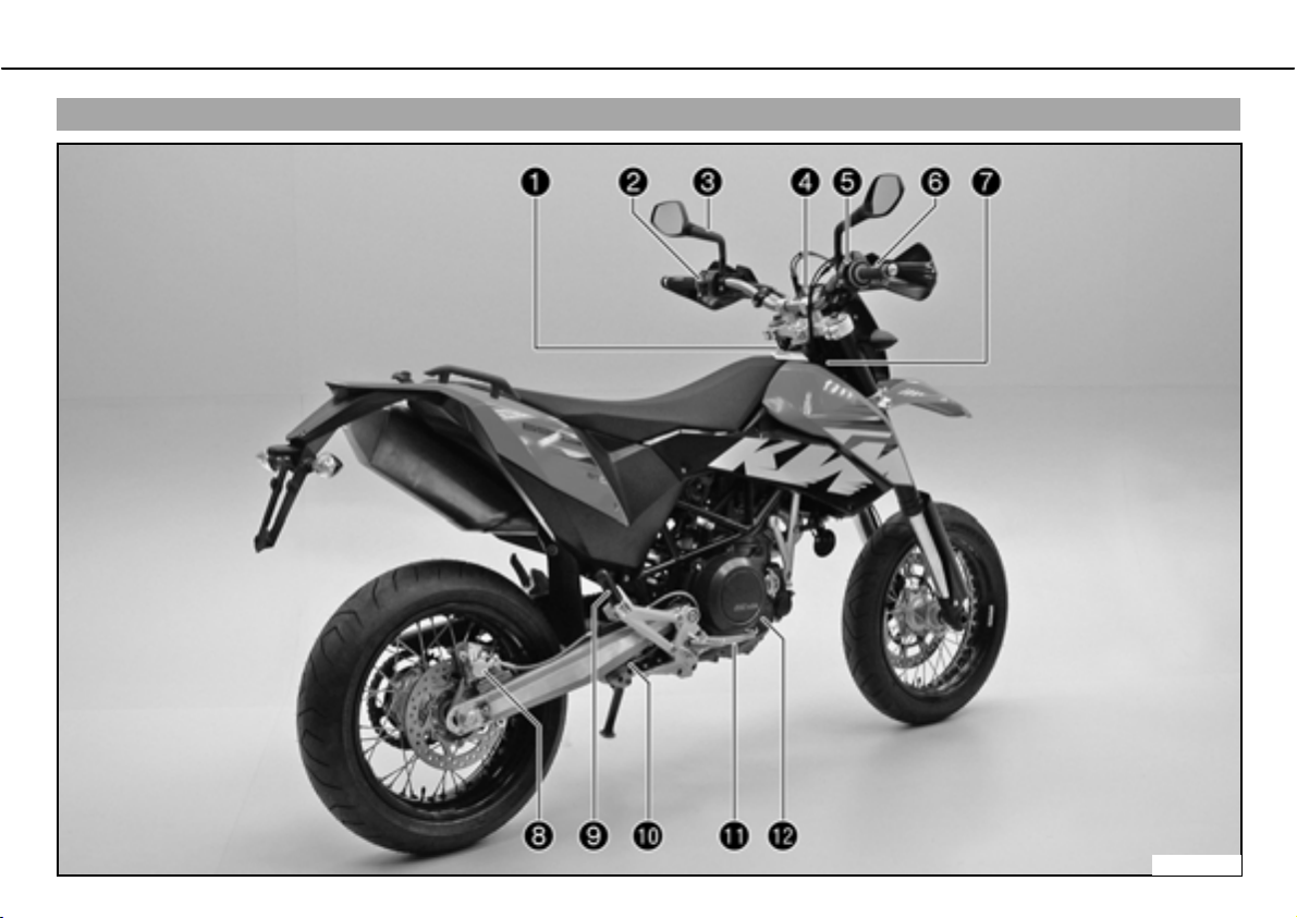
View of vehicle, rear right side
600638-10
Page 17

VIEW OF VEHICLE 15
1 Ignition/steering lock
2 Light switch, flasher switch, horn
3 Rear mirror
4 Combination instrument
5 Emergency OFF switch, electric starter button
6 Throttle grip
7 Chassis number
8 Rear brake caliper
9 Passenger footrest
10 Shock absorber rebound damping
11 Foot brake pedal
12 Engine oil level viewer
Page 18
LOCATION OF SERIAL NUMBERS 16
/2&$7,212)6(5,$/ 180%(56
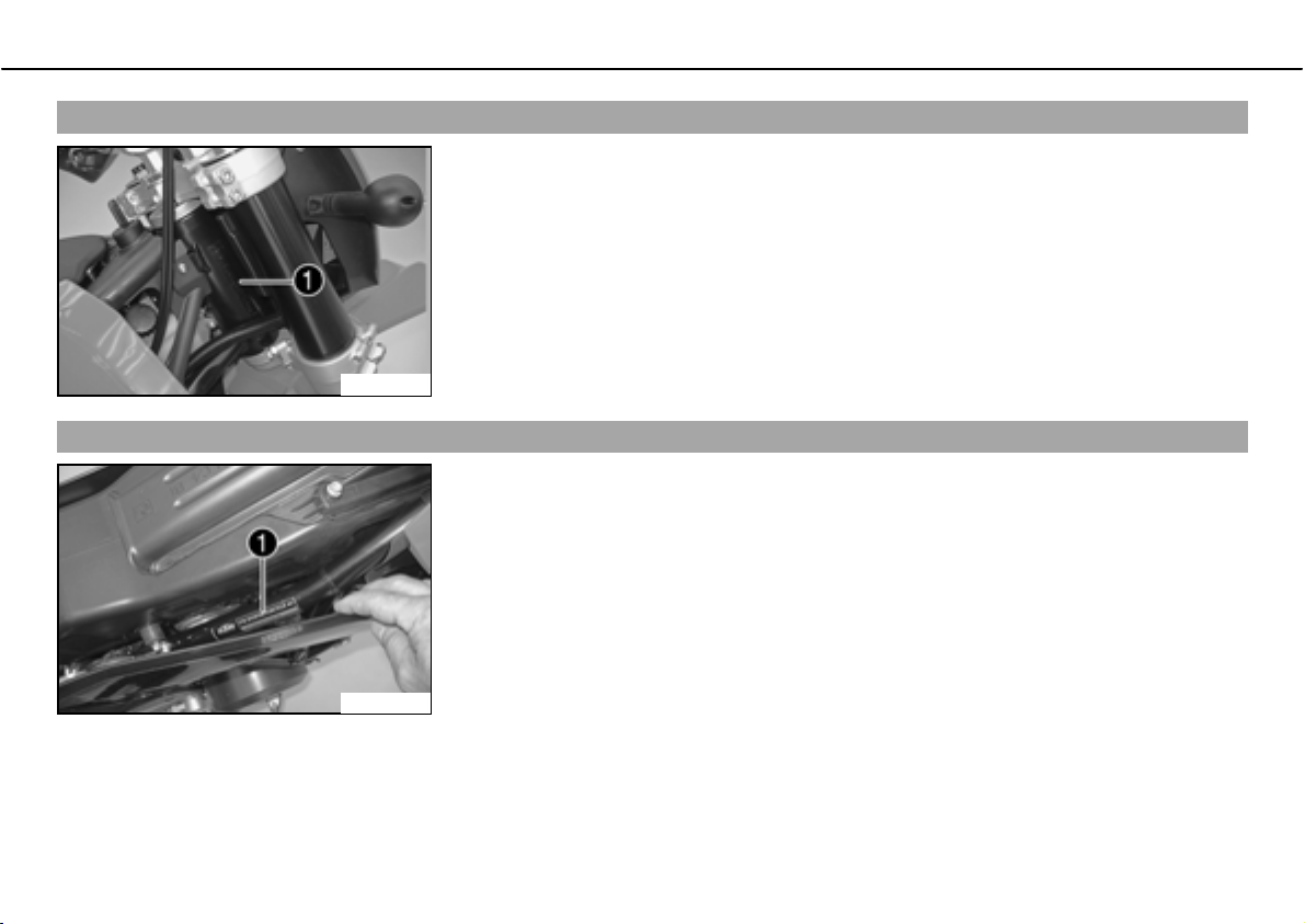
Chassis number
The chassis numberb is stamped on the steering head on the right.
100217-10
Type label
Type labelb is located on the upper right frame tube below the seat.
100218-10
Page 19
LOCATION OF SERIAL NUMBERS 17
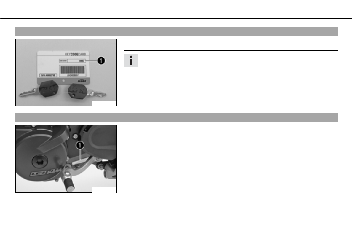
Key number
The key numberb can be found on thebKEYCODECARD.
Info
You need the key number to order a spare key. Keep thebKEYCODECARD in a safe
place.
100179-10
Engine number
The engine numberb is stamped on the left side of the engine under the engine sprocket.
600479-10
Page 20
LOCATION OF SERIAL NUMBERS 18
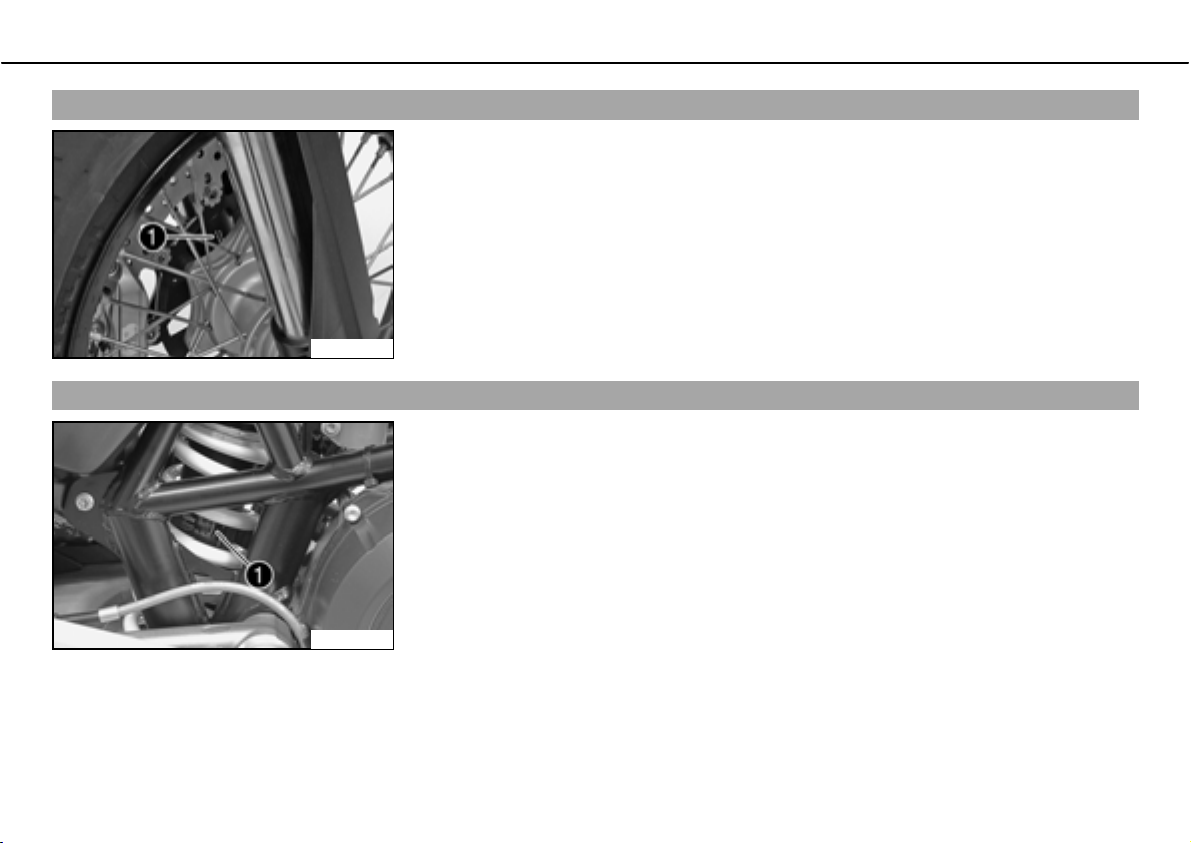
Fork part number
The fork part numberb is stamped on the inner side of the fork stub.
600480-10
Shock absorber part number
Shock absorber part numberb can be viewed from the right side.
100216-10
Page 21
OPERATING ELEMENTS 19
23(5$7,1*(/(0(176
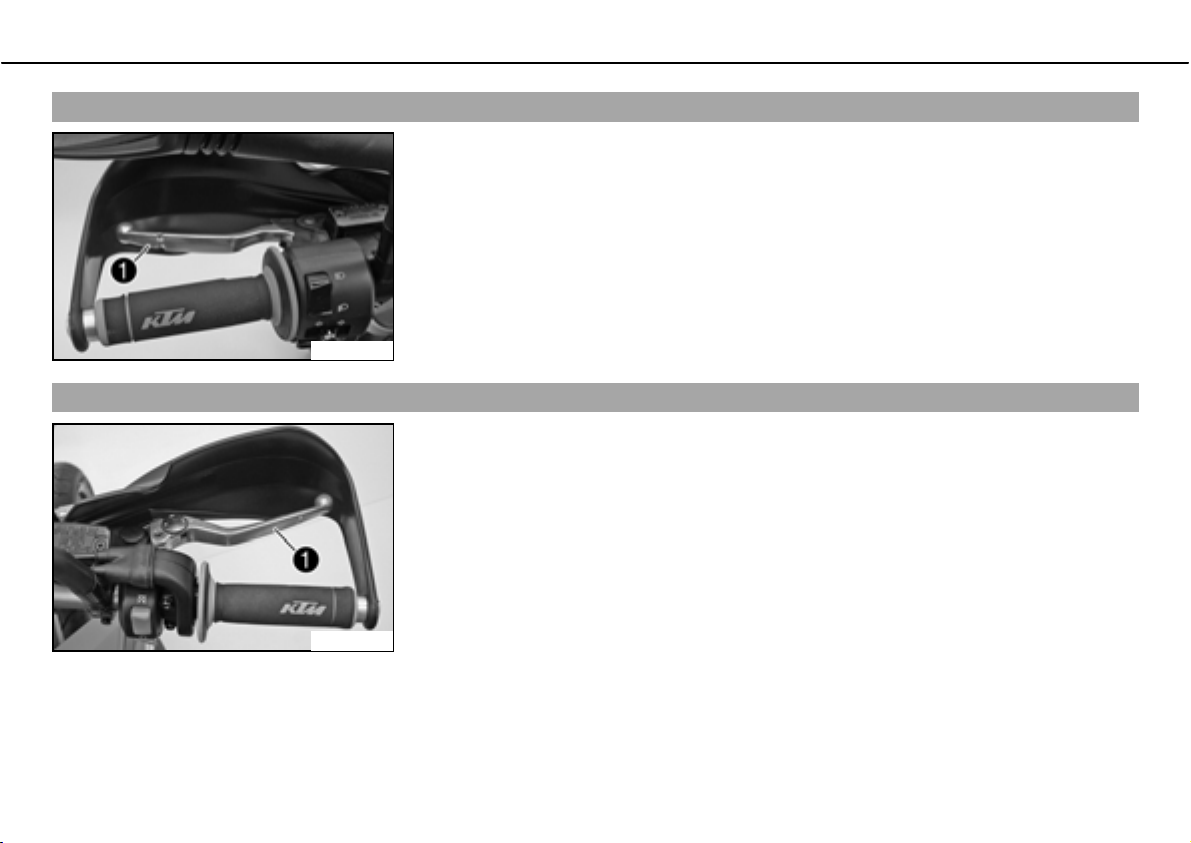
Clutch lever
The clutch leverb is fitted on the left side of the handlebar.
The clutch is hydraulically operated and self-adjusting.
600481-10
Hand brake lever
The hand brake leverb is located on the right side of the handlebar and operates the front
wheel brake.
The hand brake lever operates the front brake.
600598-11
Page 22
OPERATING ELEMENTS 20
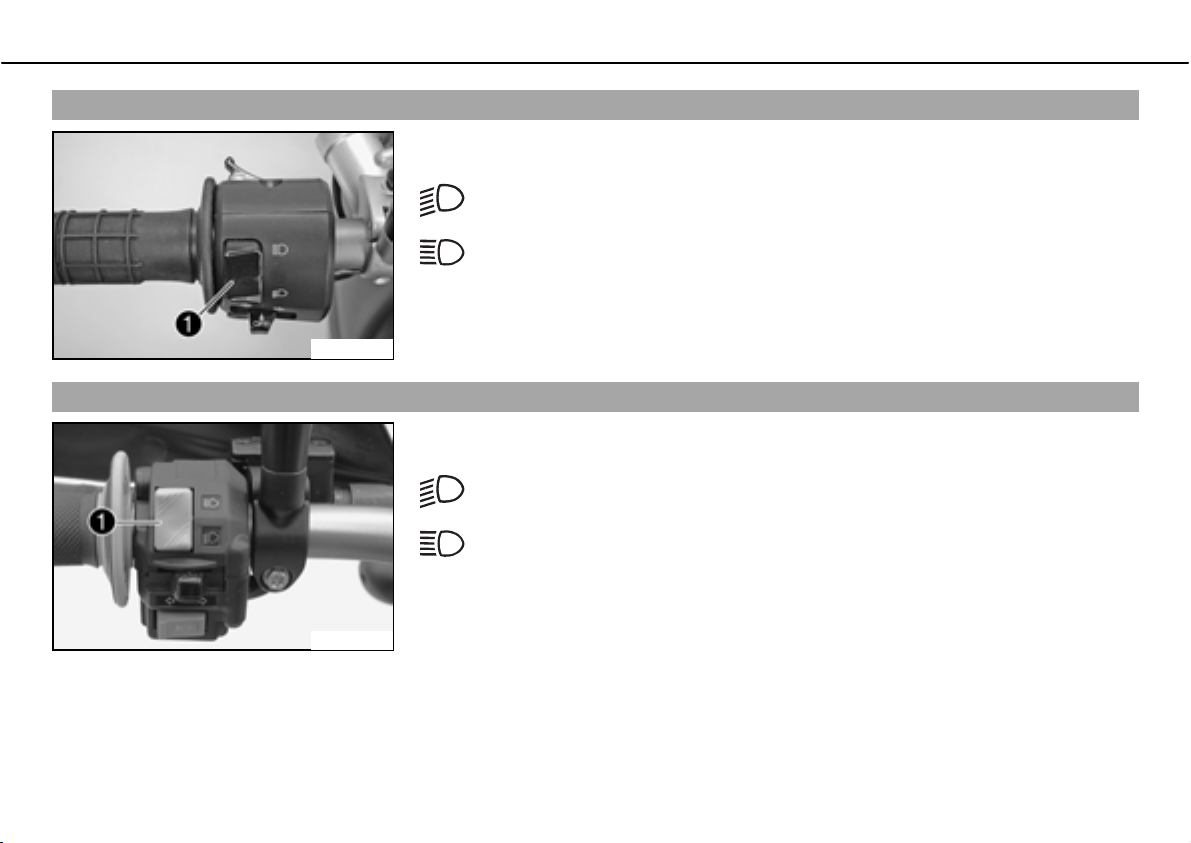
Light switch
The light switchb is fitted on the left side of the handlebar.
Possible states
Low beam on ದbLight switch is turned downwards. In this position, the low
beam and tail light are switched on.
High beam on ದbLight switch is turned upwards. In this position, the high
beam and the tail light are switched on.
500020-01
Light switch
The light switchb is fitted on the left side of the handlebar.
Possible states
Low beam on ದbLight switch is turned downwards. In this position, the low
beam and tail light are switched on.
High beam on ದbLight switch is turned upwards. In this position, the high
beam and the tail light are switched on.
100222-10
Page 23
OPERATING ELEMENTS 21
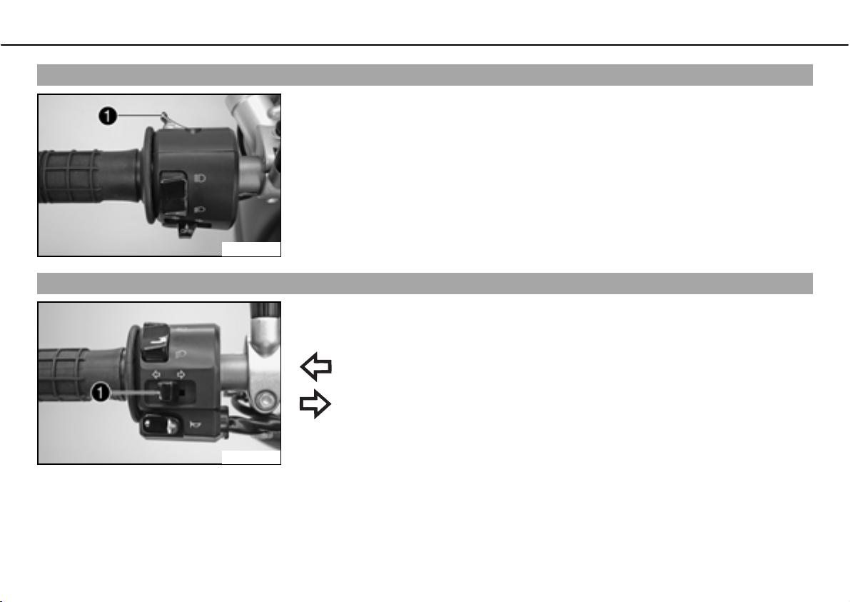
Headlight flasher switch
The headlight flasher switchb is fitted on the left side of the handlebar.
Possible states
• Headlight flasher switch in neutral position
• Headlight flasher switch pressed ದbIn this position, the headlight flasher (high beam)
is actuated.
500020-11
Flasher switch
The flasher switchb is fitted on the left side of the handlebar.
Possible states
Flasher light off
Flasher light, left, on ದbFlasher switch pressed to the right. The flasher
switch returns automatically to the central position after use.
Flasher light, right, on ದbFlasher switch pressed to the right. The flasher
switch returns automatically to the central position after use.
To switch off the flasher light, press the flasher switch towards the switch case.
500021-10
Page 24
OPERATING ELEMENTS 22
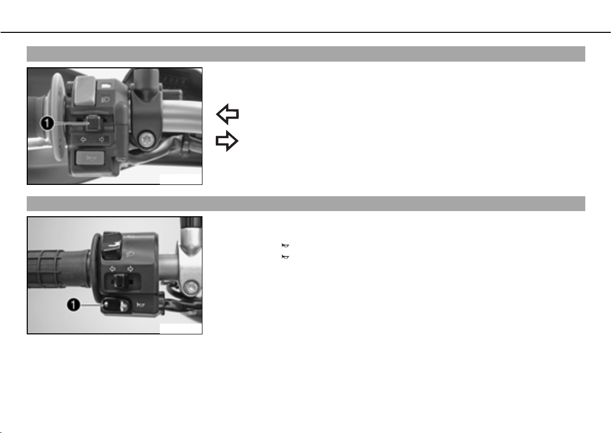
Flasher switch
The flasher switchb is fitted on the left side of the handlebar.
Possible states
Flasher light off
Flasher light, left, on ದbFlasher switch pressed to the right. The flasher
switch returns automatically to the central position after use.
Flasher light, right, on ದbFlasher switch pressed to the right. The flasher
switch returns automatically to the central position after use.
To switch off the flasher light, press the flasher switch towards the switch case.
100223-10
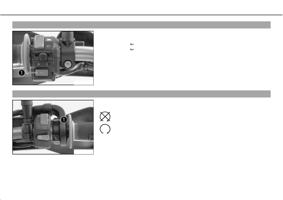
Horn
The horn buttonb is fitted on the left side of the handlebar.
Possible states
• Horn buttonb in neutral position
• Horn buttonb pressed ದbThe horn is operated in this position.
500021-11
Page 25
OPERATING ELEMENTS 23
Horn
The horn buttonb is fitted on the left side of the handlebar.
Possible states
• Horn buttonb in neutral position
• Horn buttonb pressed ದbThe horn is operated in this position.
100224-10
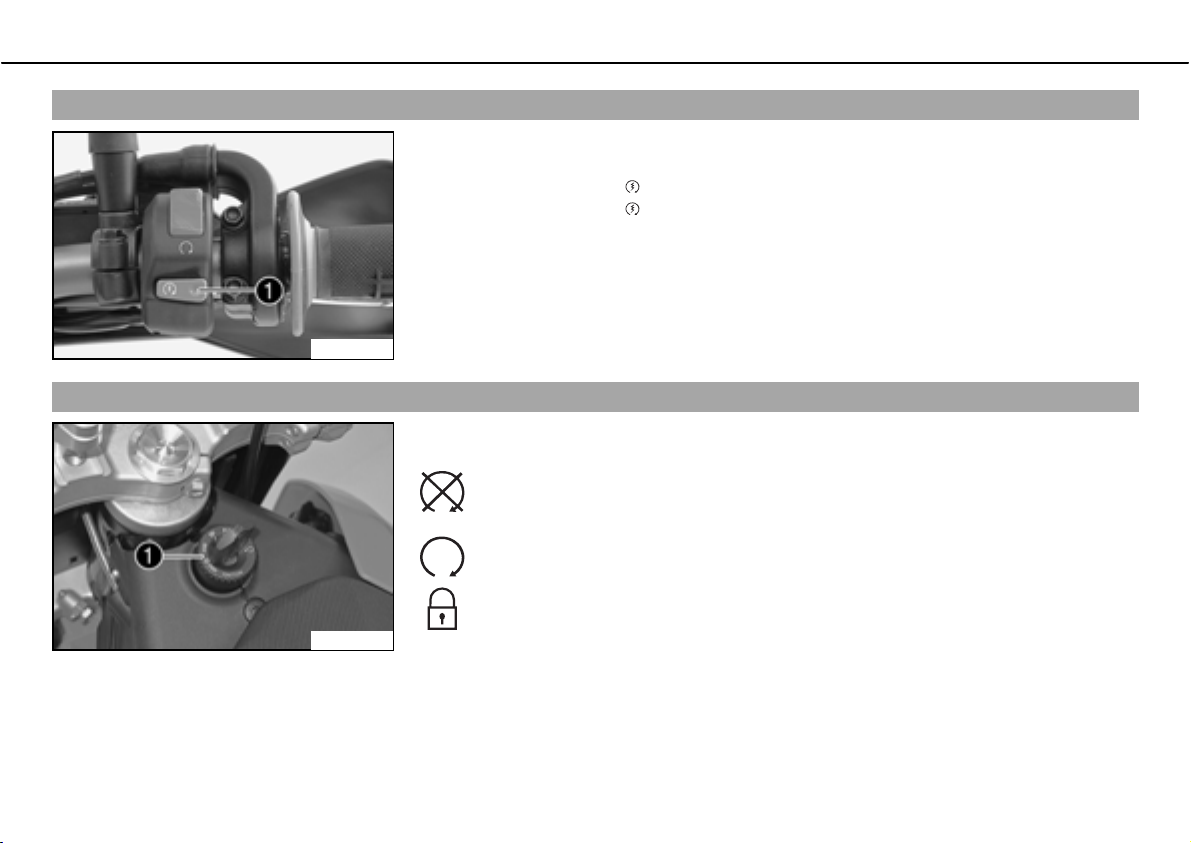
Emergency OFF switch
The emergency OFF switchb is fitted on the left side of the handlebar.
Possible states
Emergency OFF switch off ದbIn this position, the ignition circuit is interrupted, a running engine stops, and the engine cannot be started.
Emergency OFF switch on ದbThis position is necessary for operation as the
ignition circuit is closed.
100225-10
Page 26
OPERATING ELEMENTS 24
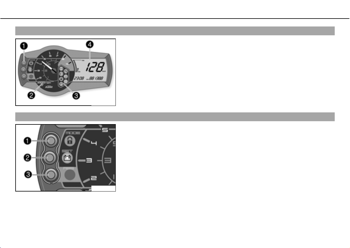
Electric starter button
The electric starter buttonb is fitted on the right side of the handlebar.
Possible states
• Electric starter buttonb in basic position
• Electric starter buttonb pressed ದbIn this position, the electric starter is actuated.
100226-10
Ignition/steering lock
The ignition/steering lockb is located in front of the seat.
Possible states
Ignition off ದbIn this position, the ignition circuit is interrupted, a running
engine stops, and a non-running engine will not start. The ignition key can
be removed.
Ignition on ದbIn this position, the ignition circuit is closed, and the engine
can be started.
Steering locked ದbIn this position, the ignition circuit is interrupted and the
steering locked. The ignition key can be removed.
100221-10
Page 27
OPERATING ELEMENTS 25
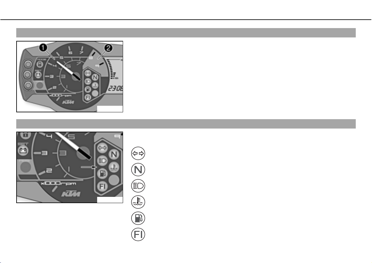
Combination instrument
The combination instrument is attached in fromt of the handlebar.
The combination instrument is divided into 4 function areas.
bFunction buttons
Tachometer
Indicator lights
Display
700116-01
Combination instrument - function buttons
Press thebMODEbbuttonb to change the display mode.
Possible display modes are total distance covered (ODO), tripmasterb1b(TRIPb1) and tripmasterb2b(TRIPb2).
Press thebSETbbuttonb
Buttonb
has no function.
to reset tripmasterb1b(TRIPb1) and tripmasterb2b(TRIPb2)tob0.0.
700117-01
Page 28
OPERATING ELEMENTS 26
Combination instrument - tachometer
The tachometerb displays the engine speed in revolutions per minute.
The red markingb
100118-10
Combination instrument - control lamps
The indicator lamps provide additional information on the operating state of the motorcycle.
Possible states
shows the excess engine speed range.
Flashing indicator flashes green in flash rhythm ದbFlasher light is switched
on.
Idling speed indicator lamp lights up green ದbTransmission is in neutral.
High beam indicator lamp lights up blue ದbHigh beam is switched on.
100119-10
Temperature warning lamp lights up red ದbCoolant has reached a critical
value.
Fuel level warning lamp lights up orange ದbFuel level has reached the reserve
mark. Display switches tobTRIPbF.
FIbwarning lampb(MIL) lights/flashes orange ದbThe OBD has detected an
emission- or safety-critical error.
Page 29
OPERATING ELEMENTS 27
Battery warning lamp lights up ದbVoltage in electrical system too low.
Combination instrument - Display
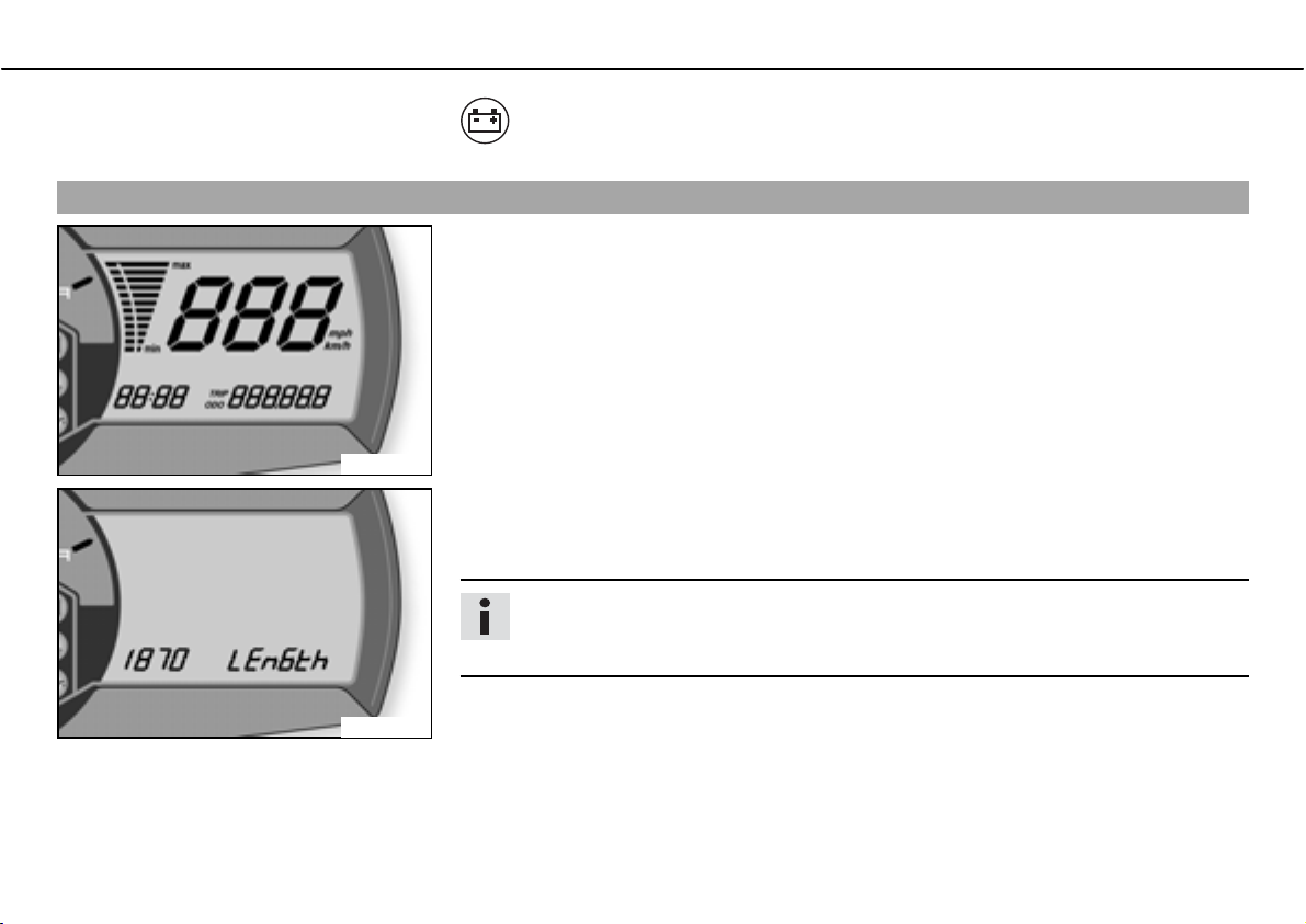
When you switch on the ignition, all display segments light up for a second as a function
test.
700118-01
LEnGTth
Following the display function test, the wheel circumferencebLEnGth is shown for one second.
Info
1870 mm corresponds to the circumference of the 17" front wheel with a series production tire.
700119-01
The display then changes to the last selected mode.
Page 30
OPERATING ELEMENTS 28
Combination instrument - speed display
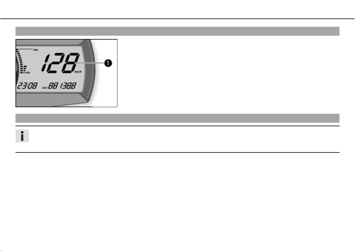
The speedb is displayed in kilometers per hourbkm/h or miles per hourbMph.
700114-01
Setting kilometers or miles
Info
If you change the unit, the ODO value is retained and converted accordingly.
Making the setting according to the country.
Condition
The motorcycle is standing.
Page 31
OPERATING ELEMENTS 29
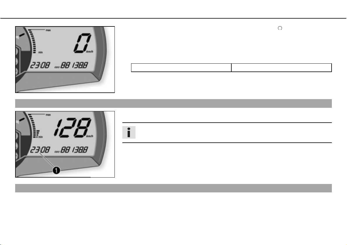
ದ Switch on the ignition by turning the ignition key in the positionb .
ದ Press thebMODEbbutton several times until thebODO display mode is active.
ದ Keep the MODEbbutton pressed until the display mode changes frombKm/h to Mph or
from Mph to Km/h.
Specification
Activation duration of MODEbbutton 10bs
700120-01
Combination instrument - time
The time is shown in areab of the display.
Info
The time must be adjusted after the battery is disconnected or the fuse is changed.
700115-01
Setting the clock
Condition
The motorcycle is standing.
Page 32
OPERATING ELEMENTS 30
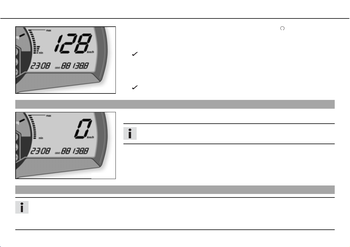
ದ Switch on the ignition by turning the ignition key in the positionb .
ದ Press thebMODEbbutton several times until thebODO display mode is active.
ದ Keep thebMODEbbutton and thebSETbbutton pressed simultaneously.
The time begins to flash.
ದ Press thebMODEbbutton to adjust the hour.
ದ Press thebSETbbutton to adjust the minute.
ದ Keep thebMODEbbutton and thebSETbbutton pressed simultaneously.
700115-10
Combination instrument -bODO display
InbODO mode, the total distance covered is shown in kilometers or miles.
700120-01
The time is set.
Info
This value remains intact even if the battery is disconnected and/or the fuse blows.
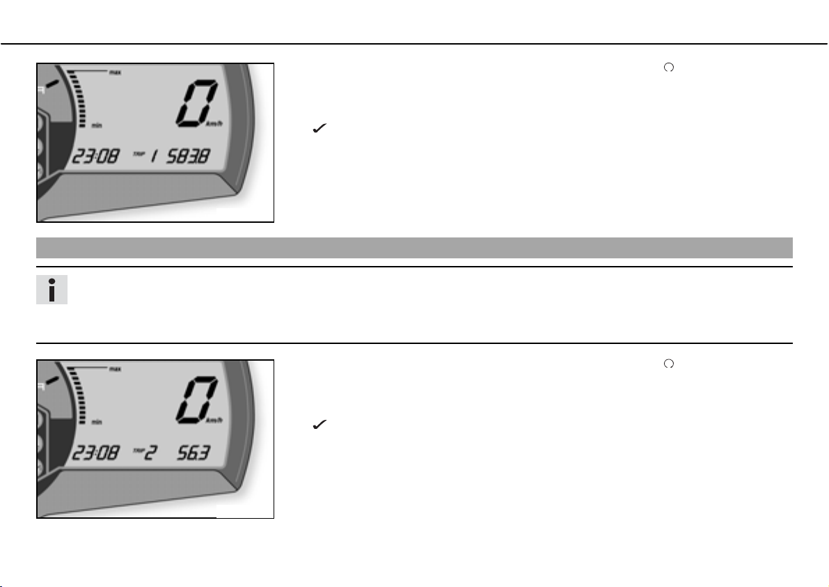
Combination instrument - setting/resettingbTRIPb1 display
Info
The tripmasterbTRIPb1 operates constantly and counts up tob999.9.
You can use the tripmaster to measure trips or the distance between refuelling stops. After reaching 999.9, the tripmaster begins
again at 0.0.
Page 33
OPERATING ELEMENTS 31
ದ Switch on the ignition by turning the ignition key in the positionb .
ದ Press thebMODEbbutton several times until thebTRIPb1 display mode is active.
ದ Keep thebSETbbutton pressed.
ThebTRIPb1 display is atb0.0.
700121-01
Combination instrument - setting/resettingbTRIPb2 display
Info
The tripmasterbTRIPb2 operates constantly and counts up tob999.9.
You can use the tripmaster to measure trips or the distance between refuelling stops. After reaching 999.9, the tripmaster begins
again at 0.0.
ದ Switch on the ignition by turning the ignition key in the positionb .
ದ Press thebMODEbbutton several times until thebTRIPb2 display mode is active.
ದ Keep thebSETbbutton pressed.
ThebTRIPb2 display is atb0.0.
700122-01
Page 34
OPERATING ELEMENTS 32
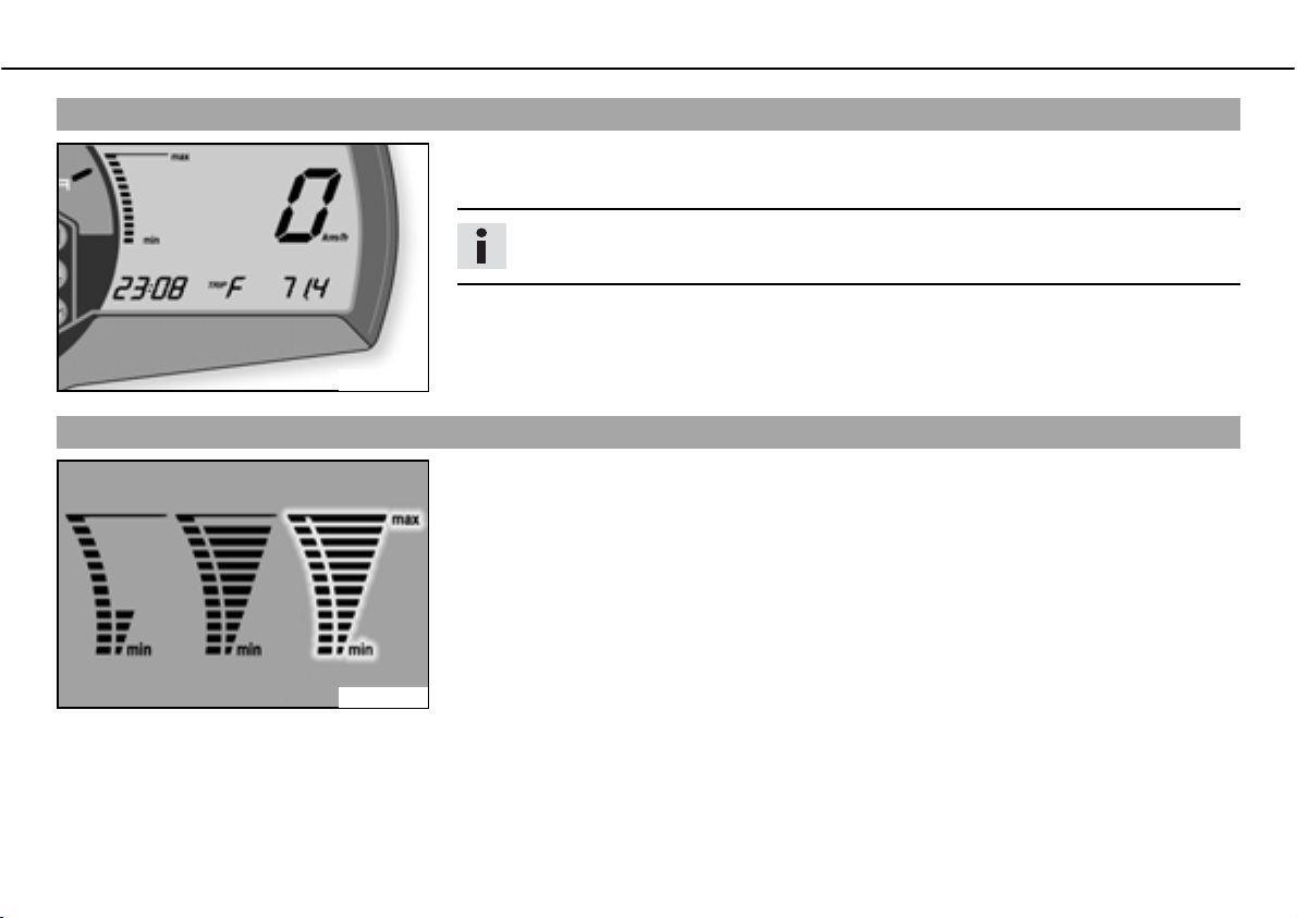
Combination instrument -bTRIPbF display
When the fuel level reaches the reserve mark, the display automatically changes tobTRIPbF
and begins to count fromb0.0, regardless of which display mode was previously active.
Info
Parallel to thebTRIPbF display, the fuel warning light begins to light up.
700123-01
Combination instrument - coolant temperature indicator
The temperature indicator in the display consists of 12 bars. The more bars that light up,
the hotter the coolant. When the top bar lights up, all bars begin to flash simultaneously
and the temperature warning lamp begins to light up.
Possible states
• Engine cold ದbup to four bars light up.
• Engine at normal operating temperature ದbfrom five to eleven bars light up.
• Engine hot ದball twelve bars flash.
700124-01
Page 35
OPERATING ELEMENTS 33
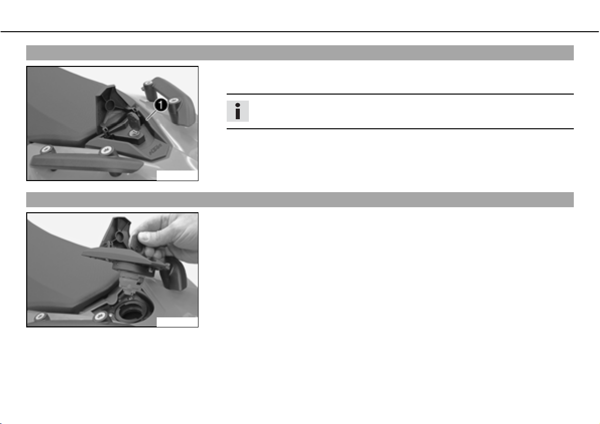
Opening filler cap
ದ Lift the cover of the filler capb and insert the ignition key.
ದ Turn the ignition key 90° counterclockwise and remove the filler cap.
Info
The filler cap has a tank air vent system.
100227-10
Closing filler cap
ದ Put the filler cap back on and turn the ignition key 90° clockwise.
ದ Remove the ignition key and fold down the cover.
100228-01
Page 36
OPERATING ELEMENTS 34
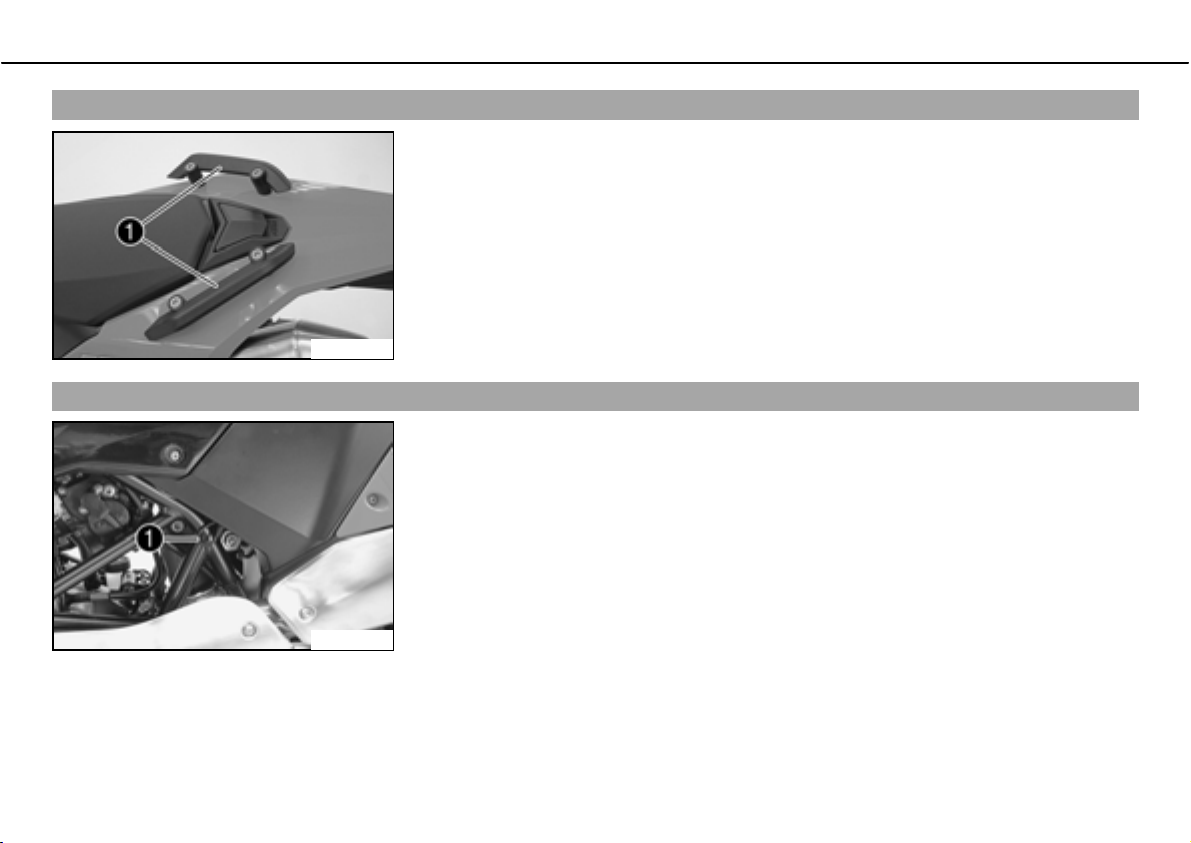
Handrails
The handrailsb are used for moving the motorcycle around.
When you have a passenger, the passenger can hold on the handrails during the journey.
100229-10
Seat release
The seat can be released using strapb.
100230-10
Page 37
OPERATING ELEMENTS 35
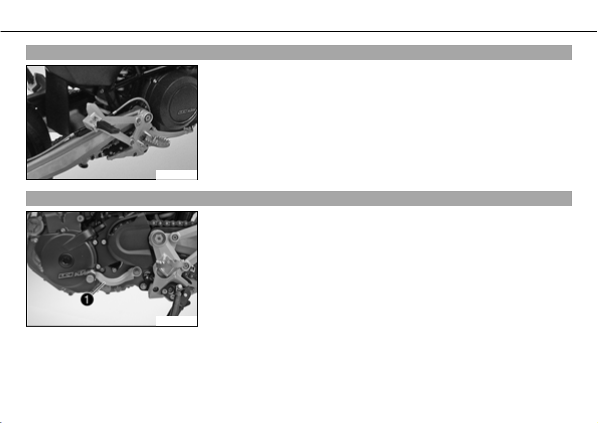
Passenger footrests
The passenger footrestsbcan be folded up and down.
Possible states
• Passenger footrests folded up ದbFor operation without a passenger.
• Passenger footrests folded down ದbFor operation with a passenger.
600640-01
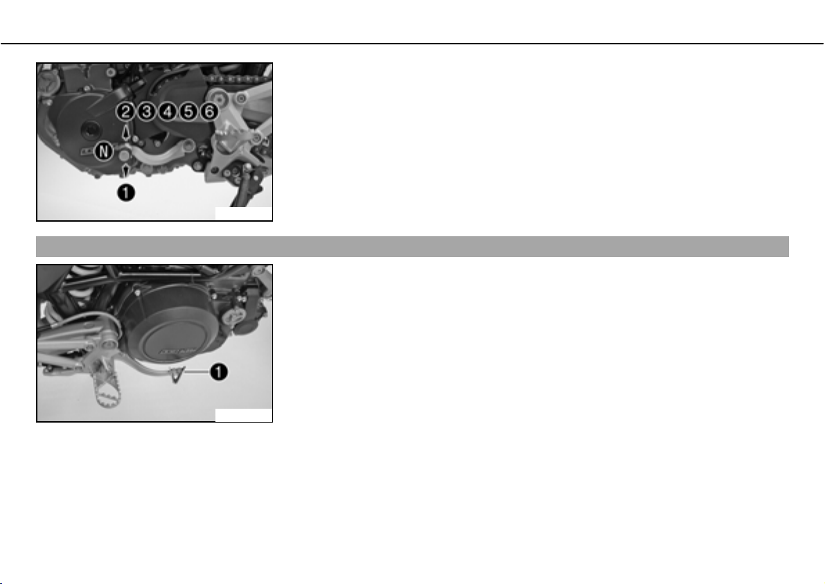
Shift lever
The shift leverb is mounted on the left side of the engine.
600484-10
Page 38
OPERATING ELEMENTS 36
The gear positions can be seen in the photograph.
The neutral or idle position is between the first and second gears.
600484-11
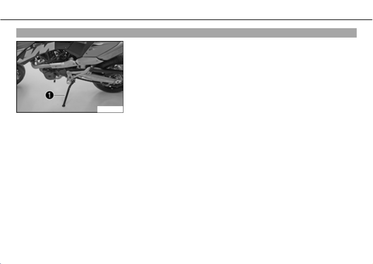
Foot brake pedal
The footbrake pedalb is located in front of the right footrest.
The footbrake pedal operates the rear brake.
600485-10
Page 39
OPERATING ELEMENTS 37
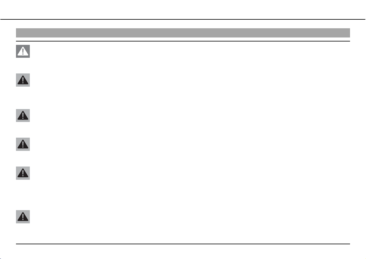
Side stand
The side standb is coupled with the safety electric starter system - see the riding instructions.
Possible states
• Side stand folded out ದbThe vehicle can be supported on the side stand. The safety
electric starter system is active.
• Side stand folded in ದbThis position is mandatory for all journeys. The safety electric
starter system is inactive.
600486-10
Page 40
GENERAL TIPS AND HINTS ON PUTTING INTO OPERATION 38
*(1(5$/7,36$1' +,17621 3877,1*,172 23(5$7,21
Advice on first use
Danger
Danger of accidentsಘDanger from inadequate traffic experience.
ದ Do not use the vehicle if you are inexperienced or if you have consumed alcohol or drugs.
Warning
Risk of injuryಘRisk of injury by missing/inadequate protective clothing.
ದ Wear protective clothing (helmet, boots, gloves, pants and jacket with protectors) every time you ride the motorcycle. Always
wear protective clothing, which must be in perfect condition and meet legal requirements.
Warning
Danger of crashingಘImpairment of riding behavior due to different tire tread patterns on front and rear wheels.
ದ The front and rear wheels must be fitted with tires with similar tread patterns to prevent loss of control over the vehicle.
Warning
Danger of accidentsಘUncontrollable handling behavior caused by non-approved tires/wheels.
ದ Use only tires/wheels approved by KTM with the corresponding speed index.
Warning
Danger of accidentsಘReduced road grip with new tires.
ದ New tires have a smooth roll surface and therefore cannot provide full road grip. The entire roll surface must be roughened in
the first 200 kilometers (124.3 miles) by moderate driving at alternating angles. The full grip is not reached until the vehicle
has been run in.
Warning
Danger of accidentsಘBrake system failure.
ದ If the foot brake pedal is not released, the brake linings drag permanently. The rear brake can fail due to overheating. Take your
foot off the foot brake pedal if you do not want to brake.
Page 41
GENERAL TIPS AND HINTS ON PUTTING INTO OPERATION 39
Info
When using your vehicle, remember that others may feel disturbed by excessive noise.
ದ Make sure that the pre-delivery inspection work has been carried out by an authorized KTM workshop.
You receive a delivery certificate and the service record at vehicle handover.
ದ Before your first trip, read the entire operating instructions carefully.
ದ Get to know the operating elements.
ದ adjust the basic position of clutch lever. ( P. 129)
ದ adjust the basic position of handbrake lever. ( P. 77)
ದ
Adjust the basic position of the foot brake pedal.b
ದ Get used to handling the vehicle on a car park before making a longer trip. Try also to ride as slowly as possible and in a standing posi-
tion to get a better feeling for the vehicle.
ದ Hold the handlebar firmly with both hands and keep your feet on the footrests when riding.
ದ Do not make any changes to the vehicle, and use only KTM approved parts.
Info
Parts from other manufacturers can reduce the operational safety of the vehicle.
ದ Run the engine in.
Running in the engine
ದ During the running-in phase, do not exceed the specified engine speed and engine performance.
Specification
Maximum engine speed
During the first: 1,000bkm (621.4bmi) 6,000brpm
After the first: 1,000bkm (621.4bmi) 7,800brpm
x ( P. 86)
Page 42
GENERAL TIPS AND HINTS ON PUTTING INTO OPERATION 40
ದ Avoid fully opening the throttle!
Loading the vehicle
Warning
Danger of accidentsಘUnstable riding behavior.
ದ Do not exceed the maximum permitted weight and axle loads. The overall weight consists of: motorcycle operational and with a
full tank, driver and passenger with protective clothing and helmet, baggage.
Warning
Danger of accidentsಘUnstable handling characteristics due to incorrect mounting of suitcase and/or tank rucksack.
ದ Mount and secure suitcase and tank rucksack according to the manufacturer's instructions.
Warning
Danger of accidentsಘUnstable handling characteristics at high speed.
ದ Adapt your speed according to your payload. Ride more slowly if your motorcycle is loaded with cases or other baggage.
Maximum speed with baggage 130bkm/h (80.8bmph)
Warning
Danger of accidentsಘRisk of breakage of suitcase system.
ದ If you have fitted suitcases on your motorcycle, read the manufacturer's specifications concerning the maximum payload.
Warning
Danger of accidentsಘPoor visibility for other road users due to slipped baggage.
ದ If the tail light is covered, you are less visible to following traffic, especially in the dark. Check the way your baggage is fixed
regularly.
Warning
Danger of accidentsಘChanged handling characteristics and longer stopping distance with excessive payload.
ದ Adapt your speed according to your payload.
Page 43
GENERAL TIPS AND HINTS ON PUTTING INTO OPERATION 41
Warning
Danger of accidentsಘUnstable handling characteristics due to slipped baggage.
ದ Check the way your baggage is fixed regularly.
Warning
Danger of burnsಘA hot exhaust system can burn baggage.
ದ Fasten your baggage in such a way that it cannot be burned or singed by the hot exhaust system.
ದ If you carry any baggage, make sure it is fixed firmly as close as possible to the center of the vehicle and ensure even weight distribu-
tion between the front and rear wheels.
ದ Do not exceed the overall maximum permitted weight and the axle loads.
Specification
Maximum permissible overall weight 350bkg (772blb.)
Maximum permissible front axle load 150bkg (331blb.)
Maximum permissible rear axle load 200bkg (441blb.)
Page 44
RIDING INSTRUCTIONS 42
5,',1*,16758&7,216
Checks before putting into operation
Info
Make sure that the motorcycle is in a perfect technical condition before use.
In the interests of riding safety, make a habit of making a general check before you ride.
ದ Check the engine oil level. ( P. 132)
ದ Check the engine for loss of oil.
ದ Check the fuel level.
ದ Bleed fork legs. ( P. 63)
Specification
all 1,000bkm (621.4bmi)
ದ Check the chain tension. ( P. 71)
ದ Clean the chain. ( P. 70)
ದ Check the tire condition. ( P. 100)
ದ Checking the tire air pressure. ( P. 102)
ದ Check the front brake brake fluid level. ( P. 78)
ದ Check the rear brake fluid level. ( P. 87)
ದ Check the front brake linings. ( P. 81)
ದ Check the rear brake linings. ( P. 90)
ದ Check brake system function.
ದ Check the coolant level. ( P. 124)
ದ Check that all operating elements are correctly adjusted and free to move.
ದ Check the functioning of the electrical equipment.
ದ Check that baggage is correctly secured.
ದ Sit on the motorcycle and check the rear mirror setting.
Page 45
RIDING INSTRUCTIONS 43
Starting
Danger
Danger of poisoningಘExhaust gases are poisonous and can result in unconsciousness and/or death.
ದ When running the engine, always make sure there is sufficient ventilation, and do not start or run the engine in a closed space.
Caution
Danger of accidentsಘIf the vehicle is operated with a discharged battery or without a battery, electronic components and safety
equipment may be damaged.
ದ Never operate the vehicle with a discharged battery or without a battery.
Note
Engine failureಘHigh engine speeds in cold engines have a negative effect on the service life of the engine.
ದ Always warm up the engine at low engine speeds.
Page 46
RIDING INSTRUCTIONS 44
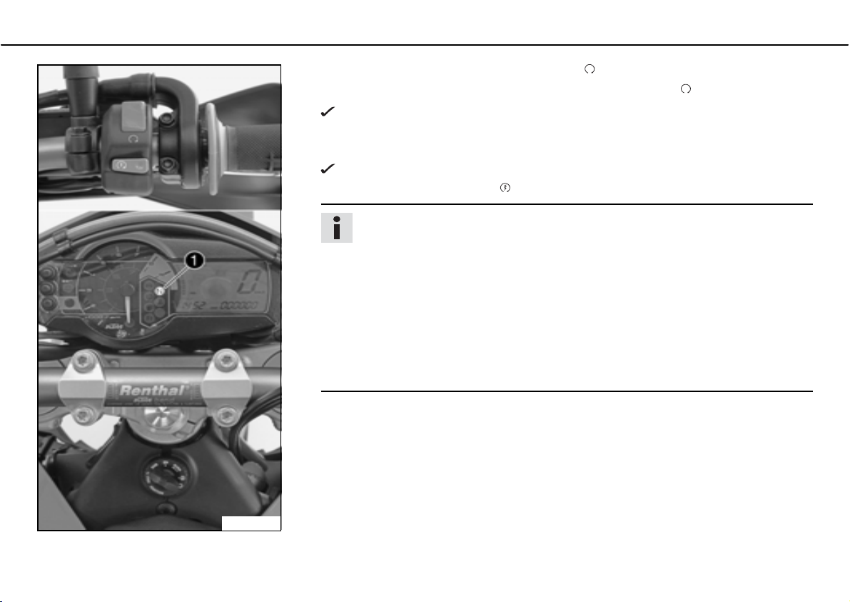
ದ Turn the emergency OFF switch to thebpositionb .
ದ Switch on the ignition by turning the ignition key in the positionb .
After switching on the ignition, you can hear the fuel pump working for about 2
seconds. At the same time, the combination instrument runs a function test.
ದ Shift gear to neutral.
The green idling speed indicator lampbNb
ದ Press the electric starter buttonb .
Info
Do not press the electric starter button until the combination instrument function test is finished.
Do not open the throttle when starting. If you open the throttle when starting,
the engine management injects no fuel and the engine cannot start.
Press the starter for a maximum of 5 seconds. Wait for at least 5 seconds until
trying again.
This motorcycle is equipped with a safety electric starter system. The engine
can be started only if the gearbox is in neutral or the clutch lever is pulled. If
you shift into gear when the side stand is folded out and then release the clutch
lever, the engine stalls.
ದ Take the weight off the side stand and swing it back up with your foot as far as it will
go.
lights up.
100239-10
Page 47
RIDING INSTRUCTIONS 45
Starting up
ದ Pull the clutch lever, engage 1st gear, release the clutch lever slowly and simultaneously open the throttle carefully.
Shifting, riding
Warning
Danger of accidentsಘAn abrupt load alterations can cause the vehicle to get out of control.
ದ Avoid abrupt load alterations and sudden braking actions, and adapt your speed to the road conditions.
Warning
Danger of accidentsಘIf you change down at high engine speed, the rear wheel can lock up.
ದ Do not change into a low gear at high engine speed. The engine races and the rear wheel can block.
Warning
Danger of accidentsಘMalfunctions caused by incorrect ignition key position.
ದ Do not change the ignition key position during a journey.
Warning
Danger of accidentsಘDistraction from traffic activity by adjustments to the vehicle.
ದ Make all adjustments when the vehicle is at a standstill.
Warning
Risk of injuryಘThe passenger must be capable of sitting correctly on the passenger seat.
ದ The passenger must hold on to the rider or the handrails and place his feet on the passenger footrests. Note the regulations
governing the minimum age of passengers in your country.
Warning
Danger of accidentsಘDanger of accidents caused by dangerous driving.
ದ Observe the traffic regulations and ride defensively and with foresight in order to recognize danger as early as possible.
Page 48
RIDING INSTRUCTIONS 46
Warning
Danger of accidentsಘReduced road grip with cold tires.
ದ On every journey, take the first miles carefully at moderate speed until the tires reach operating temperature and optimal road
grip is ensured.
Warning
Danger of accidentsಘReduced road grip with new tires.
ದ New tires have a smooth roll surface and therefore cannot provide full road grip. The entire roll surface must be roughened in
the first 200 kilometers (124.3 miles) by moderate driving at alternating angles. The full grip is not reached until the vehicle
has been run in.
Warning
Danger of accidentsಘUnstable riding behavior.
ದ Do not exceed the maximum permitted weight and axle loads. The overall weight consists of: motorcycle operational and with a
full tank, driver and passenger with protective clothing and helmet, baggage.
Warning
Danger of accidentsಘUnstable handling characteristics due to slipped baggage.
ದ Check the way your baggage is fixed regularly.
Warning
Danger of accidentsಘAfter a fall, check the vehicle.
ದ After a fall, check the vehicle as usual before putting it into operation.
Note
Engine failureಘUnfiltered intake air has a negative effect on the service life of the engine.
ದ Never ride the vehicle without an air filter since dust and dirt can get into the engine and result in increased wear.
Page 49
RIDING INSTRUCTIONS 47
Note
Engine failureಘOverheating of engine.
ದ If the coolant temperature warning lamp lights up, stop and switch off the engine. Allow the engine to cool down and check the
coolant level in the radiator, and top up if necessary. If you continue with the coolant temperature warning lamp alight, you may have
engine failure.
Info
If you hear unusual noises while riding, stop immediately, switch off the engine and contact an authorized KTM workshop.
ದ When conditions allow (incline, road situation, etc.), you can shift into a higher gear.
ದ Release the throttle while simultaneously pulling the clutch lever, shift into the next
gear, release the clutch and open the throttle.
Info
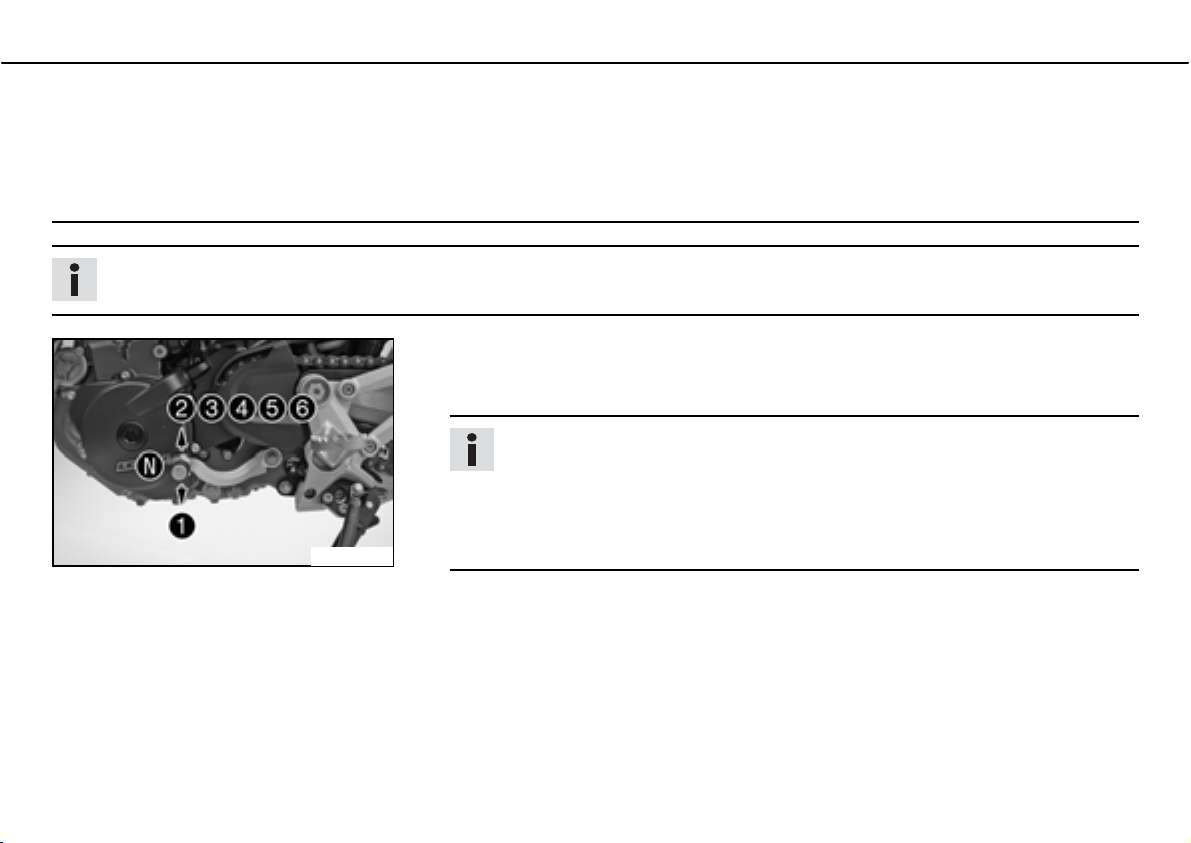
For the positions of the 6 forward gears, see the illustration. The neutral or idle
position is between the first and second gears. First gear is used for starting off
or for steep inclines.
The operating temperature is reached when 5 bars of the temperature indicator
600484-11
ದ When you reach maximum speed after fully opening the throttle, turn back the throttle
ದ Open the throttle only as far as the road and weather conditions permit. Particularly in
ದ To shift down, brake if necessary and close the throttle at the same time.
ದ Pull the clutch lever and shift into a lower gear, release the clutch lever slowly and open
light up.
to about ¾ of its range; the speed hardly drops, but the fuel consumption falls considerably.
bends, do not shift and open the throttle only very cautiously.
the throttle or shift again.
Page 50
RIDING INSTRUCTIONS 48
ದ For example, if the engine stalls at a junction, just pull the clutch and press the electric
starter button. You do not need to shift into neutral.
ದ Switch off the engine if you expect to be standing for a long time.
ದ Avoid frequent and longer slipping of the clutch. This heats the engine oil, the engine
and the cooling system.
ದ Ride with a lower engine speed instead of with a high engine speed and a slipping
clutch.
ದ If the FIbwarning lampb(MIL) starts to light up during the journey, stop immediately. If
you shift to neutral, thebFIbwarning lampb(MIL) begins to flash.
Info
From the flash rhythm, you can deduce a two-digit number, the so-called flash
code. The flash code tells you which component is affected by a fault.
Braking
Warning
Danger of accidentsಘIf you brake too hard, the wheels can lock.
ದ Adapt your braking to the traffic situation and the road conditions.
Warning
Danger of accidentsಘReduced braking due to wet or dirty brakes.
ದ Clean or dry dirty or wet brakes by riding and braking gently.
Warning
Danger of accidentsಘReduced braking caused by spongy pressure point of front or rear brake.
ದ Have the brake system checked in an authorized KTM workshop, and do not ride any further.
Page 51
RIDING INSTRUCTIONS 49
Warning
Danger of accidentsಘBrake system failure.
ದ If the foot brake pedal is not released, the brake linings drag permanently. The rear brake can fail due to overheating. Take your
foot off the foot brake pedal if you do not want to brake.
Warning
Danger of accidentsಘLonger stopping distance due to higher overall weight.
ದ Take the longer stopping distance into account when carrying a passenger and baggage.
Warning
Danger of accidentsಘDelayed brake action on salted roads.
ದ Salt can be deposited on the brake discs. To achieve the normal braking effect, the brake discs must first be cleaned by brak-
ing.
ದ To brake, release the throttle and operate the front and rear brakes simultaneously.
ದ On sandy, wet or slippery surfaces, use the rear brake.
ದ Braking should always be completed before you go into a bend. Change down to a lower gear appropriate to your road speed.
ದ On long downhill stretches, use the braking effect of the engine. Change down one or two gears, but do not overstress the engine. In
this way, you have to brake far less and the brakes do not overheat.
Stopping, parking
Warning
Risk of misappropriationಘUsage by unauthorized persons.
ದ Never leave the vehicle while the engine is running. Secure the vehicle against use by unauthorized persons. If you leave the
vehicle, lock the steering and remove the ignition key.
Page 52
RIDING INSTRUCTIONS 50
Warning
Danger of burnsಘSome vehicle components get very hot when the machine is driven.
ದ Do not touch hot components such as exhaust system, radiator, engine, shock absorber and brakes. Allow these components to
cool down before starting work on them.
Note
Danger of damageಘDanger of damage by the vehicle running away or falling over.
ದ Always place the vehicle on a firm and even surface.
Note
Fire hazardಘSome components (engine, radiator and exhaust system) get very hot when the engine is running.
ದ Do not place the vehicle where there are flammable or explosive substances.
Note
Material damageಘDamage and destruction of components by excessive load.
ದ The side stand is designed for the weight of the motorcycle only. Do not sit on the motorcycle when it is supported by the side stand
only. The side stand and/or the frame could be damaged and the motorcycle could fall over.
ದ Brake the motorcycle.
ದ Shift gear to neutral.
ದ Switch off the ignition by turning the ignition key in the positionb .
Info
If the engine is switched off with the emergency OFF switch and the ignition remains switched on at the ignition lock, power
continues to flow to most power consumers and the battery will discharge. You should therefore always switch off the engine
with the ignition key - the emergency OFF switch is intended for emergencies only.
ದ Park the motorcycle on a hard surface.
ದ Swing the side stand forward with your foot as far as it will go and lean the vehicle on it.
Page 53
RIDING INSTRUCTIONS 51
ದ Lock the steering by moving the handlebar to the left, pressing down the ignition key in the positionb and turning it to the positionb .
To make locking the steering easier, move the handlebar a little to the left and right. Remove the ignition key.
Refueling
Danger
Fire hazardಘFuel can easily catch fire.
ದ Never fill up the vehicle near open flames or burning cigarettes, and always switch off the engine first. Be careful that no fuel is
spilt, especially on hot vehicle components. Clean up spilt fuel immediately.
ದ Fuel in the fuel tank expands when warm and can escape if the tank is overfilled. See specifications on filling up with fuel.
Warning
Danger of poisoningಘFuel is poisonous and a health hazard.
ದ Avoid contact between fuel and skin, eyes and clothing. Do not inhale fuel vapors. If fuel gets into your eyes, rinse immediately
with water and contact a doctor. Wash affected skin areas immediately with soap and water. If fuel is swallowed, contact a doctor immediately. Change clothing that has come into contact with fuel.
Warning
Environmental hazardಘImproper handling of fuel is a danger to the environment.
ದ Do not allow fuel to get into the ground water, the ground, or the sewage system.
Info
This motorcycle is equipped with a regulated catalyst. Leaded fuel will destroy the catalyst. You should therefore use unleaded fuel
only.
Page 54
RIDING INSTRUCTIONS 52
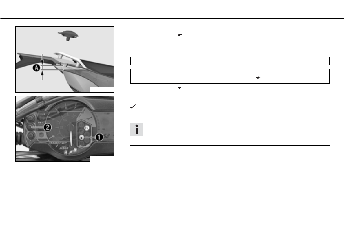
ದ switch off engine.
ದ Open the filler cap. ( P. 33)
ದ Fill the fuel tank with fuel up to measurementb
Specification
Measurement ofb
Fuel tank content 12bl (3.2bUSbgal) Super unleaded (ROZ 95 / RON 95 /
20bmm (0.79bin)
.
PON 91) ( P. 165)
400405-10
100240-10
ದ Close the filler cap. ( P. 33)
ದ Press thebSETb function button for 2 seconds.
The fuel level warning lampb
previous display mode.
switches off. TRIPbF is set to 0 and appears in the
Info
If you do not press thebSETb function button, the reset takes place automatically after about 3 minutes.
Page 55
GREASING AND SERVICE TABLE 53
*5($6,1*$1'6(59,&( 7$%/(
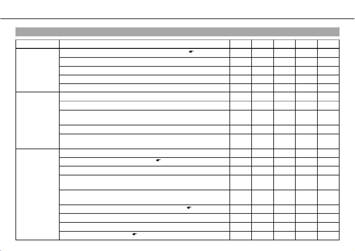
Important maintenance work to be carried out by an authorized KTM workshop.
K10N K50A K100A J1A J2A
Engine
Fuel injection
Attachments Check the cooling system for leakage. • • • • •
Change engine oil and oil filter, clean oil screens.b
Check and adjust valve clearance.b
Check engine mounting screws for tightness. • • • • •
Replace spark plug. •
Check engine bolts accessible from outside for tightness. • • • • •
Check connection boots for cracks and leakage.b
Read out the error memory with a KTM diagnostic tool.b
Check fuel hoses, SLS hoses and vent hoses for damage, correct fit-
ting and leaks.b
Clean, check and grease the O-ring of the fuel hose connection.b
Check the cable harness of the throttle valve body for damage and cor-
rect positioning.b
Check the antifreeze and coolant level. ( P. 122) • • • • •
Check the functioning of the radiator fan.b
Check the exhaust system for leaks and correct fitting and check that
the exhaust holders are tight.b
Check Bowden cables for damage, smooth operation, routing without
sharp bends and setting.
Check/correct the fluid level of the hydraulic clutch. ( P. 129) • • • •
Check air filter and change if necessary. Clean the air filter box.b
Check cables for damage and routing without sharp bends.b
Check the headlamp setting. ( P. 118) • • • • •
x
x
x
x
x
x ( P. 132)
x
x
x
x
x
•••••
••
•••
•••••
•••••
••••
•••
•••••
•••••
•••••
••••
•••••
Page 56
GREASING AND SERVICE TABLE 54
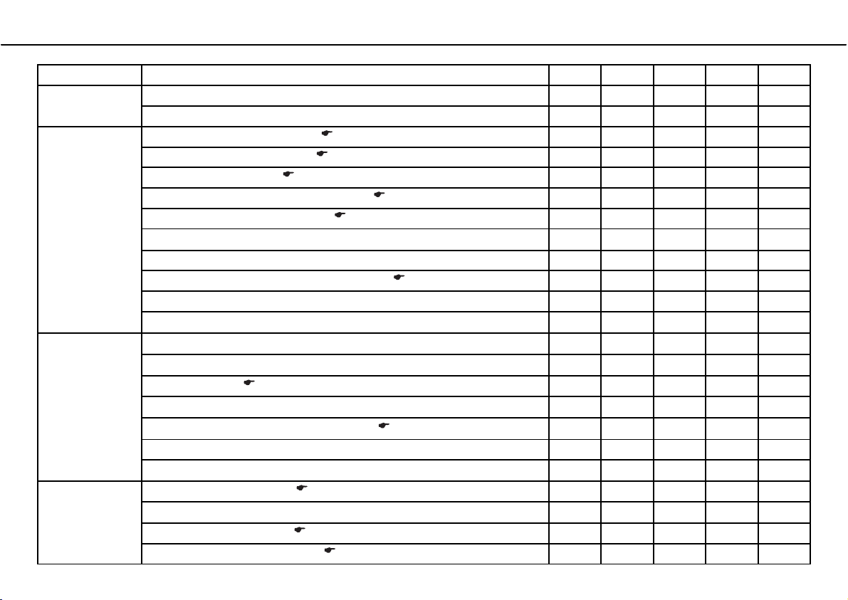
K10N K50A K100A J1A J2A
Attachments Check the functioning of the electrical equipment. • • • • •
Check screws and nuts for tightness. • • • • •
Brakes Check the front brake linings. ( P. 81) • • • • •
Check the rear brake linings. ( P. 90) • • • • •
Check the brake discs. ( P. 76) • • • • •
Check the front brake brake fluid level. ( P. 78) • • • • •
Check the rear brake fluid level. ( P. 87) • • • • •
Change brake fluid.b
Check brake lines for damage and leakage. • • • • •
Check the free play of the foot brake lever. ( P. 86) • • • • •
Check braking. • • • • •
Check screws and guide bolts of brake system for tightness.b
Chassis
Wheels Check the spoke tension. ( P. 101) • • • • •
Check shock absorber and fork for leakage and functioning.bx
Clean dust boots of fork legs.b
Bleed fork legs. ( P. 63) • • • • •
Check swingarm bearing.b
Check play of steering head bearing.b
Check all screws to see if they are tight. • • • • •
Grease ProತLever deflector.b
Check rim run-out.b
Check the tire condition. ( P. 100) • • • • •
Checking the tire air pressure. ( P. 102) • • • • •
x
x
x
x
x
x ( P. 66)
x
•••••
•••••
••••
•••••
•••••
•••••
•
•
Page 57
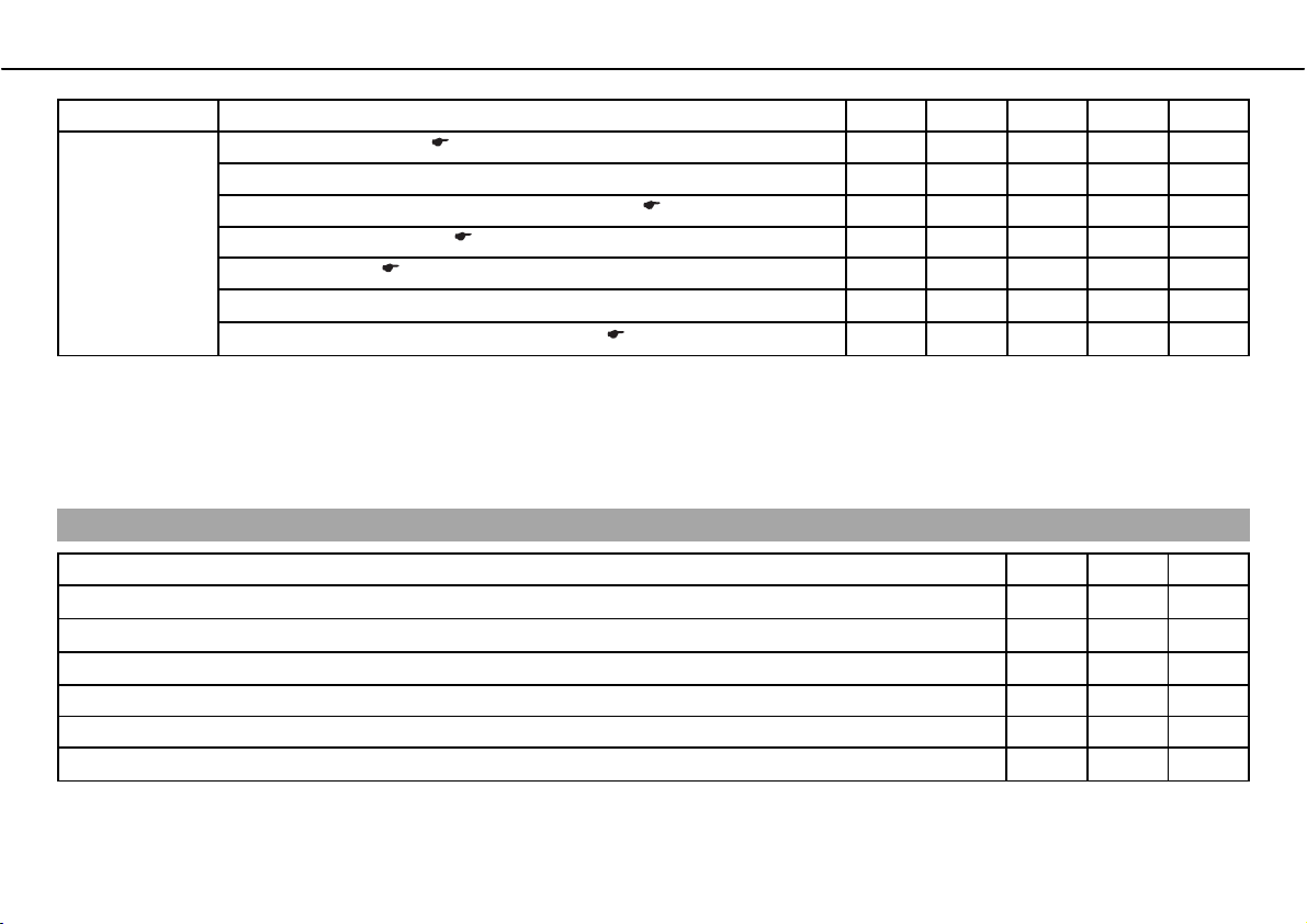
GREASING AND SERVICE TABLE 55
K10N K50A K100A J1A J2A
Wheels Check the chain wear. ( P. 75) • • • • •
Check rear sprocket / engine sprocket for tightness. • • • • •
Check rear sprocket / engine sprocket for wear. ( P. 74) • • • • •
Check the chain tension. ( P. 71) • • • • •
Clean the chain. ( P. 70) • • • • •
Check wheel bearing for play.b
Checking the rear hub rubber dampers.b
K10N: after 1,000 km (621.4 mi)
K50A: every 5,000 km (3,107 mi) / after every race
K100A: every 10,000 km (6,214 mi)
J1A: annually
J2A: every 2 years
Important maintenance work to be carried out by an authorized KTM workshop. (as additional order)
Carry out a complete fork service.b
Carry out a complete shock absorber service.b
Clean and grease steering head bearing and sealing elements.b
Treat electric contacts with contact spray. ••
Clean the battery terminals and treat them with contact grease. • •
Change coolant.b
x
x
x
x ( P. 99)
x
x
••••
••••
K100A J1A J2A
••
••
•
•
K100A: every 10,000 km (6,214 mi)
J1A: annually
J2A: every 2 years
Page 58
MAINTENANCE WORK ON CHASSIS AND ENGINE 56
0$,17(1$1&(:25. 21&+$66,6 $1'(1*,1(
Jacking up front of motorcycle
Note
Danger of damageಘDanger of damage by the vehicle running away or falling over.
ದ Always place the vehicle on a firm and even surface.
ದ Jack up the rear of the motorcycle. ( P. 57)
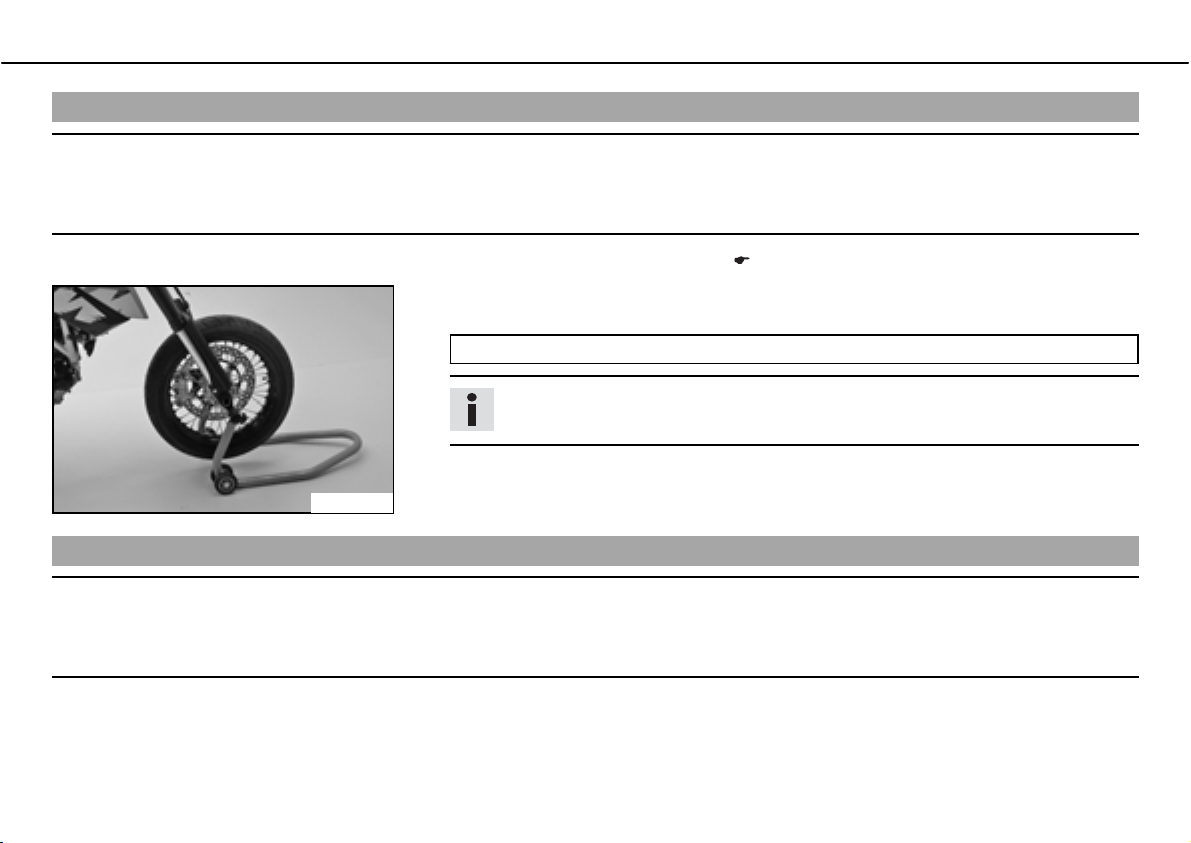
ದ Move the handlebar to the straight-ahead position. Align the work stand to the front
with the adapters to the fork legs.
Work stand front (61029055300)
Info
Always jack up the rear of the motorcycle first.
ದ Jack up the front of the motorcycle.
600493-01
Taking front from work stand
Note
Danger of damageಘDanger of damage by the vehicle running away or falling over.
ದ Always place the vehicle on a firm and even surface.
ದ Secure the motorcycle against falling over.
ದ Remove the work stand at the front.
Page 59
MAINTENANCE WORK ON CHASSIS AND ENGINE 57
Jacking up rear of motorcycle
Note
Danger of damageಘDanger of damage by the vehicle running away or falling over.
ದ Always place the vehicle on a firm and even surface.
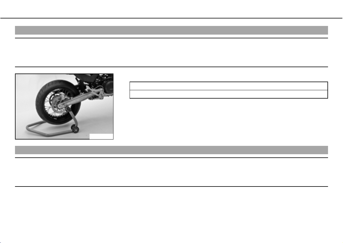
ದ Insert the work stand adapter in the work stand and screw it into the link forks.
Work stand adapter (61029055110)
Work stand rear (61029055100)
ದ Stand the motorcycle upright, align the work stand to the rear, and jack up the motorcy-
cle.
600492-01
Take the rear from the work stand.
Note
Danger of damageಘDanger of damage by the vehicle running away or falling over.
ದ Always place the vehicle on a firm and even surface.
ದ Secure the motorcycle against falling over.
ದ Remove the work stand from the rear and lean the vehicle on the side stand.
Page 60
MAINTENANCE WORK ON CHASSIS AND ENGINE 58
Fork/shock absorber
The fork and the shock absorber offer many options of adapting the chassis to your riding
style and the payload.
Info
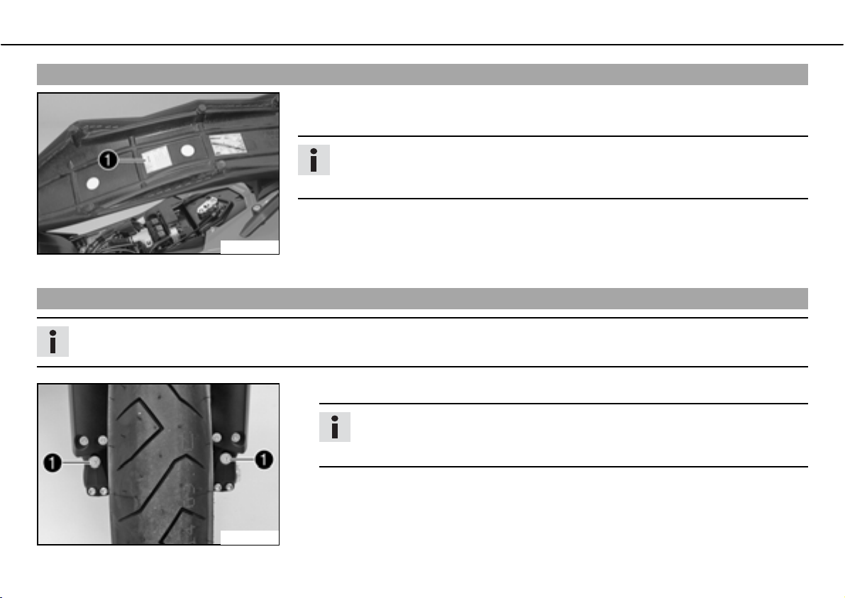
To help you adapt the vehicle, we have summarized our findings in Tableb. You
can find the table on the underside of the seat.
These adjustments should be understood as a guideline and should always be the basis
100242-01
Adjusting compression damping of fork
Info
The hydraulic compression damping determines the fork suspension behavior.
of your own personal chassis adaptation. Do not change the adjustments at random or by
more than ± 40%, since otherwise the riding characteristics could deteriorate, particularly
at high speeds.
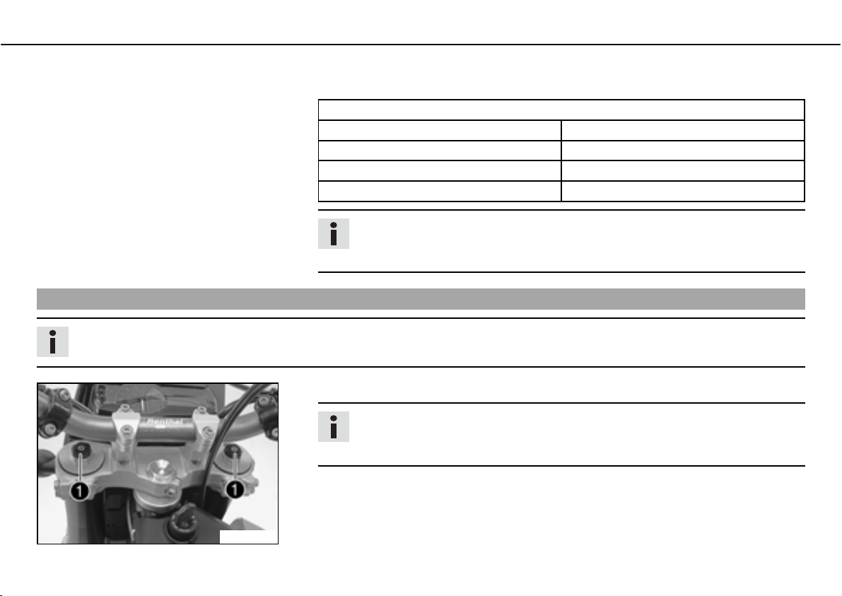
ದ Turn adjusting screwsb clockwise until they stop.
Info
The adjusting screws are located at the bottom end of the fork legs.
Make the same adjustment on both fork legs.
600490-10
Page 61
MAINTENANCE WORK ON CHASSIS AND ENGINE 59
ದ Turn back counterclockwise the number of clicks corresponding to the fork type.
Specification
Compression damping
Comfort 20bclicks
Standard 15bclicks
Sport 10bclicks
full payload 10bclicks
Info
Turn clockwise to increase damping, turn counterclockwise to reduce suspension
damping.
Adjusting rebound damping of fork
Info
The hydraulic rebound damping determines the fork suspension behavior.
ದ Turn adjusting screwsb clockwise until they stop.
Info
The adjusting screws are located at the top end of the fork legs.
Make the same adjustment on both fork legs.
100244-10
Page 62
MAINTENANCE WORK ON CHASSIS AND ENGINE 60
ದ Turn back counterclockwise the number of clicks corresponding to the fork type.
Specification
Rebound damping
Comfort 15bclicks
Standard 10bclicks
Sport 5bclicks
full payload 5bclicks
Info
Turn clockwise to increase damping, turn counterclockwise to reduce suspension
damping.
Compression damping of shock absorber
The shock absorber can regulate compression damping in low- and high-speed range separately (Dual Compression Control).
The term low and high speed refers to the movement of the shock absorber during compression and not the riding speed of the motorcycle.
The low- and high-speed technology works non-specifically.
Adjusting the low-speed compression damping of the shock absorber
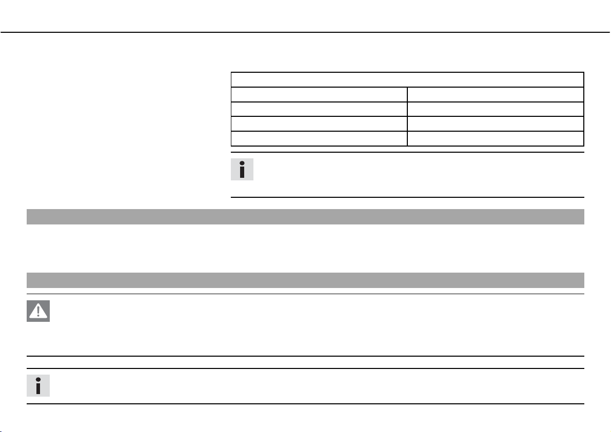
Danger
Danger of accidentsಘThe shock absorber is under high pressure.
ದ The shock absorber is filled with highly compressed nitrogen, so never dismantle the shock absorber or carry out any mainte-
nance on it yourself.
Info
The low-speed setting can be seen during the slow to normal compression of the shock absorber.
Page 63
MAINTENANCE WORK ON CHASSIS AND ENGINE 61
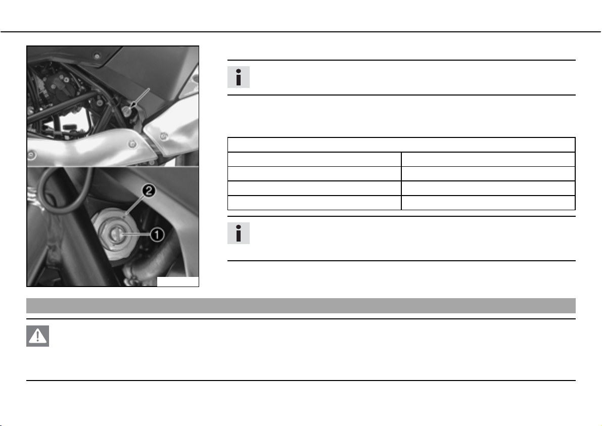
ದ Turn the adjusting screwb clockwise with a screwdriver until it stops.
Info
Do not loosen nutb!
ದ Turn back counterclockwise the number of clicks corresponding to the shock absorber
type.
Specification
Compression damping, low-speed
Comfort 20bclicks
Standard 15bclicks
Sport 10bclicks
full payload 10bclicks
Info
Turn clockwise to increase damping, turn counterclockwise to reduce suspension
damping.
100245-10
Adjusting high-speed compression damping of the shock absorber
Danger
Danger of accidentsಘThe shock absorber is under high pressure.
ದ The shock absorber is filled with highly compressed nitrogen, so never dismantle the shock absorber or carry out any mainte-
nance on it yourself.
Page 64
MAINTENANCE WORK ON CHASSIS AND ENGINE 62
Info
The high-speed setting can be seen during the fast compression of the shock absorber.
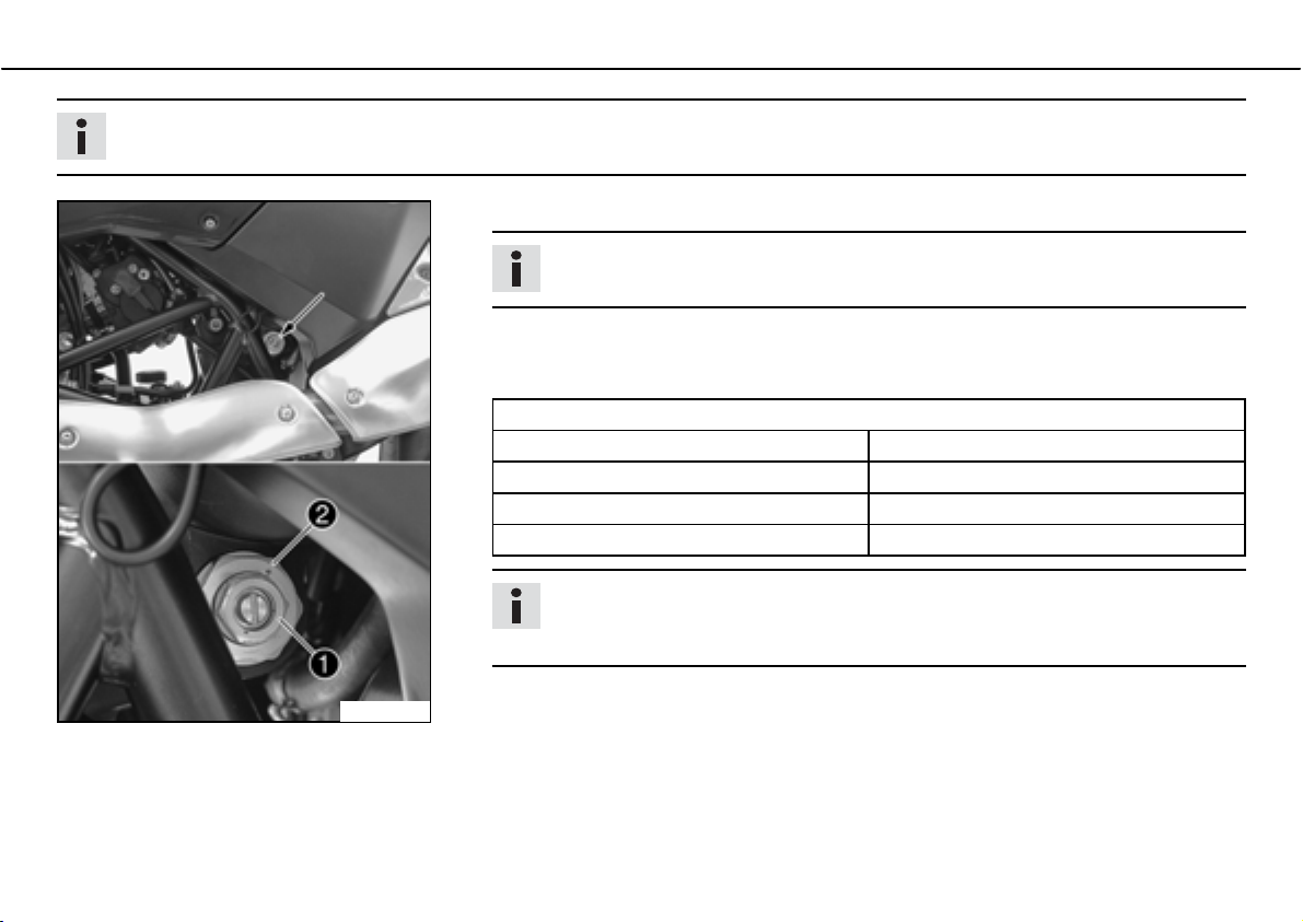
ದ Turn the adjusting screwb clockwise with an open-ended spanner until it stops.
Info
Do not loosen nutb!
ದ Turn back counterclockwise the number of turns corresponding to the shock absorber
type.
Specification
Compression damping, high-speed
Comfort 1.5bturns
Standard 1bturn
Sport 0.5bturn
full payload 0.5bturn
Info
Turn clockwise to increase damping, turn counterclockwise to reduce suspension
damping.
100246-10
Page 65
MAINTENANCE WORK ON CHASSIS AND ENGINE 63
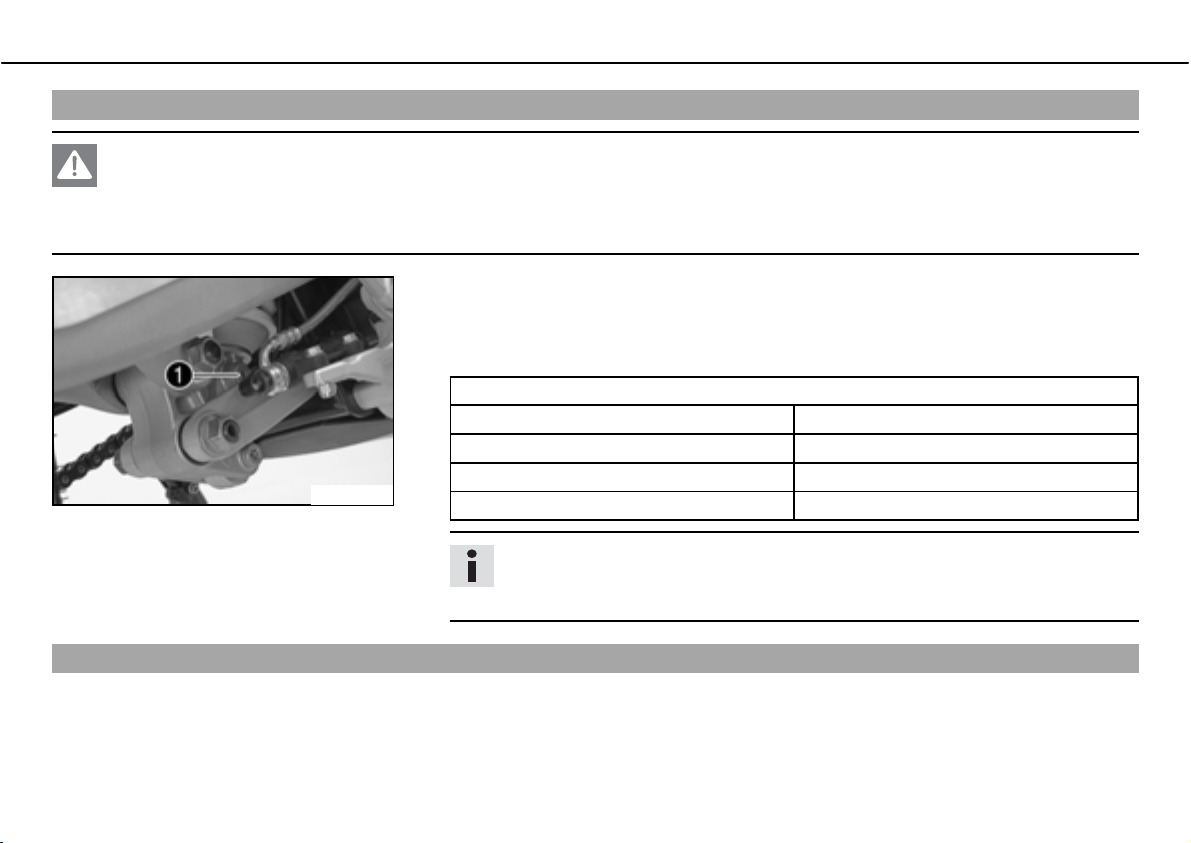
Adjusting rebound damping of the shock absorber
Danger
Danger of accidentsಘThe shock absorber is under high pressure.
ದ The shock absorber is filled with highly compressed nitrogen, so never dismantle the shock absorber or carry out any mainte-
nance on it yourself.
ದ Turn the adjusting screwb clockwise until it stops.
ದ Turn back counterclockwise the number of clicks corresponding to the shock absorber
type.
Specification
Rebound damping
Comfort 20bclicks
Standard 15bclicks
100247-10
Sport 10bclicks
full payload 10bclicks
Info
Turn clockwise to increase damping, turn counterclockwise to reduce suspension
damping.
Bleeding fork legs
ದ Lean the motorcycle on the side stand.
Page 66

MAINTENANCE WORK ON CHASSIS AND ENGINE 64
ದ Remove bleeder screwsb briefly.
Any excess pressure escapes from the interior of the fork.
ದ Mount and tighten bleeder screws.
Info
Carry out this action on both fork legs.
100248-10
Cleaning dust boots of fork legs
ದ Jack up the motorcycle and secure it against falling over.
The front wheel is not in contact with the ground and there is no weight on the fork
legs.
ದ Remove the fork protector. ( P. 65)
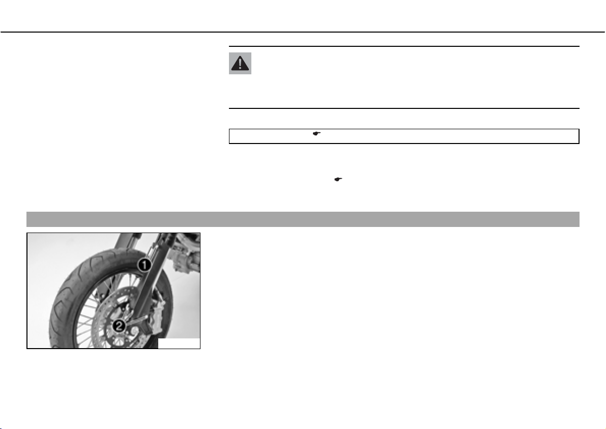
ದ Push dust bootsb of both fork legs downwards.
Info
The dust boots should remove dust and coarse dirt particles from the fork tubes.
Over time, dirt can penetrate behind the dust boots. If this dirt is not removed,
the oil seals behind can start to leak.
600634-10
Page 67
MAINTENANCE WORK ON CHASSIS AND ENGINE 65
Warning
Danger of accidentsಘReduced braking due to oil or grease on the brake discs.
ದ Always keep the brake discs free of oil and grease, and clean them with
brake cleaner when necessary.
ದ Clean and oil the dust boots and inner fork tube of both fork legs.
Universal oil spray ( P. 168)
ದ Press the dust boots back into their normal position.
ದ Remove excess oil.
ದ Install the fork protector. ( P. 66)
ದ Remove the motorcycle from the work stand.
Removing the fork protector
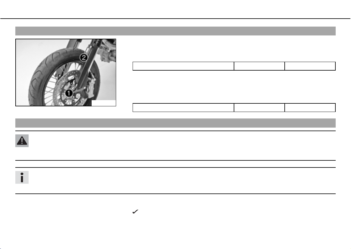
ದ Remove screwsb and take off clamp.
ದ Remove screwsb
ದ Remove the screws on the right fork leg. Remove the fork protector.
on left fork leg. Remove the fork protector.
600633-11
Page 68
MAINTENANCE WORK ON CHASSIS AND ENGINE 66
Installing the fork protector
ದ Check parts for damage and wear. Replace damaged or worn parts.
ದ Position the fork protection on the left fork leg. Mount and tighten screwsb
Specification
Remaining screws, chassis M6 10bNm (7.4blbfbft)
ದ Position the brake line and cable harness. Put the clamp on, mount and tighten
screwsb
.
ದ Position the fork protection on the right fork leg. Mount and tighten the screws.
600633-10
Checking play of steering head bearingbx
Specification
Remaining screws, chassis M6 10bNm (7.4blbfbft)
Warning
Danger of accidentsಘUnsafe riding behavior due to incorrect steering head bearing play.
ದ The steering head bearing play should be adjusted immediately in an authorized KTM workshop.
Info
If the bike is driven for a longer time with play in the steering head bearing, the bearing and the bearing seats in the frame can be
damaged after time.
.
ದ Jack up the motorcycle and secure it against falling over.
The front wheel is not in contact with the ground and there is no weight on the fork
legs.
Page 69
MAINTENANCE WORK ON CHASSIS AND ENGINE 67
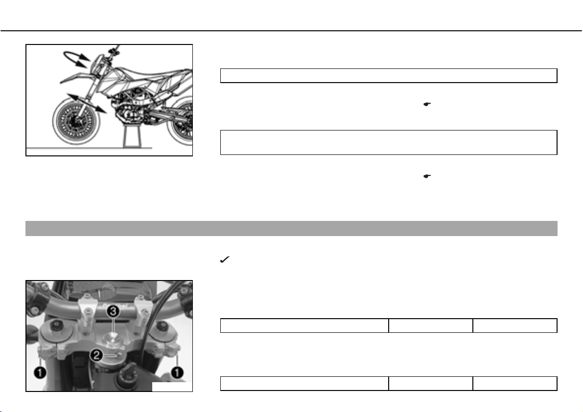
ದ Move the handlebar to the straight-ahead position. Move the fork legs to and fro in the
direction of travel.
No play should be noticeable in the steering head bearing.
» If there is noticeable play present:
ದ
ದ Move the handlebar to and fro over the entire steering range.
600636-10
ದ Remove the motorcycle from the work stand.
Adjusting play of steering head bearingbx
ದ Jack up the motorcycle.
ದ Loosen screwb. Remove screwb.
ದ Loosen and retighten screwb
Adjust play of the steering head bearing.b
The handlebar must be able to move easily over the entire steering range. No resting
locations should be noticeable.
» If click positions are noticeable:
ದ
Adjust play of the steering head bearing.b
ದ Check the steering head bearing and change if necessary.
The front wheel is not in contact with the ground and there is no weight on the fork
legs.
.
Specification
Screw, top steering head M20x1.5 10bNm (7.4blbfbft)
x ( P. 67)
x ( P. 67)
100297-10
ದ Using a plastic hammer, tap lightly on the upper triple clamp to avoid strains.
ದ Fully tighten screwb
Specification
Screw, top triple clamp M8 17bNm (12.5blbfbft)
.
Page 70
MAINTENANCE WORK ON CHASSIS AND ENGINE 68
Handlebar position
00AA
00BB
400271-11
ದ Mount and tighten screwb
Specification
Screw, steering stem M8 20bNm
ದ
Check play of steering head bearing.b
ದ Remove the motorcycle from the work stand.
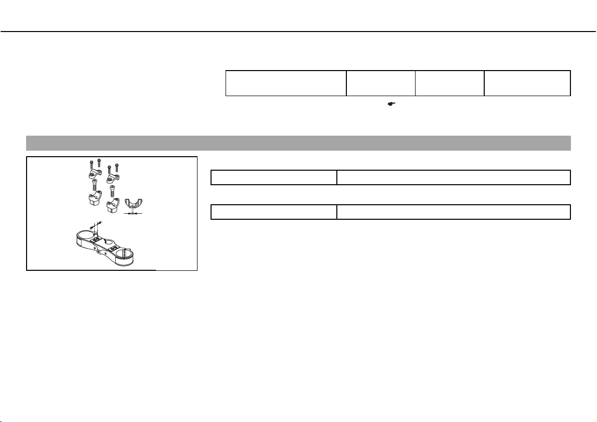
On the upper triple clamp, there are 2 holes at a distanceb to each other.
Distanceb
The holes on the handlebar support are placed at a distanceb
Distanceb
The handlebar can be mounted in 4 different positions. In this way, the handlebar can be
installed in the position most comfortable for the rider.
between holes 15bmm (0.59bin)
between holes 3.5bmm (0.138bin)
.
x ( P. 66)
(14.8blbfbft)
from the center.
Loctite
®
243™
Page 71
MAINTENANCE WORK ON CHASSIS AND ENGINE 69
Adjusting handlebar positionbx
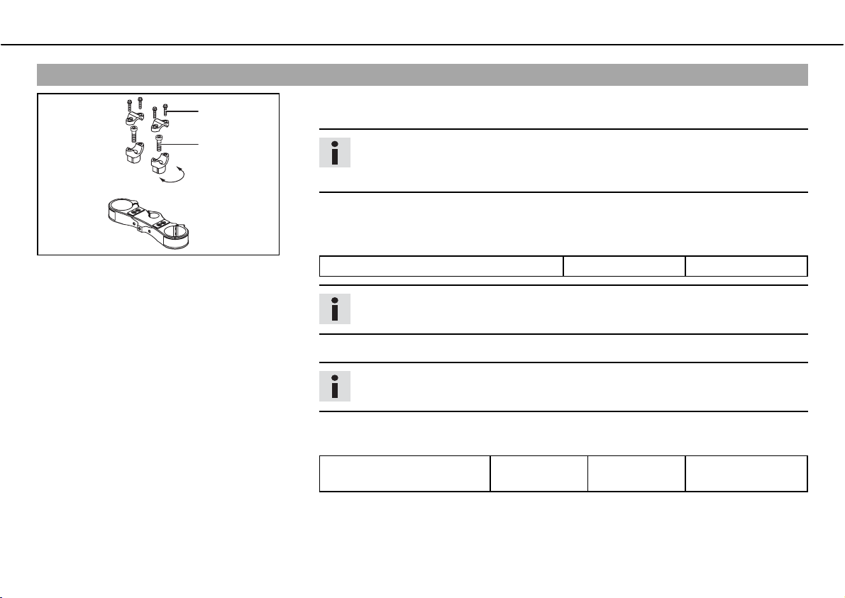
ದ Remove the four screwsb. Remove the handlebar clamp. Remove the handlebar and
0011
lay it to one side.
0022
400271-10
Info
Protect the motorcycle and its attachments from damage by covering them.
Do not bend the cables and lines.
ದ Remove the two screwsb
ದ Place the handlebar support in the required position. Fit and tighten the two screwsb
Specification
Screw, handlebar support M10 40bNm (29.5blbfbft)
. Remove the handlebar support.
Info
Position the left and right handlebar supports evenly.
ದ Position the handlebar.
Info
Make sure cables and wiring are positioned correctly.
ದ Position the handlebar clamp. Fit and evenly tighten the four screwsb
Specification
Screw, handlebar clamp M8 20bNm
(14.8blbfbft)
.
Loctite
®
243™
.
Page 72
MAINTENANCE WORK ON CHASSIS AND ENGINE 70
Adjusting the handlebar anglebx
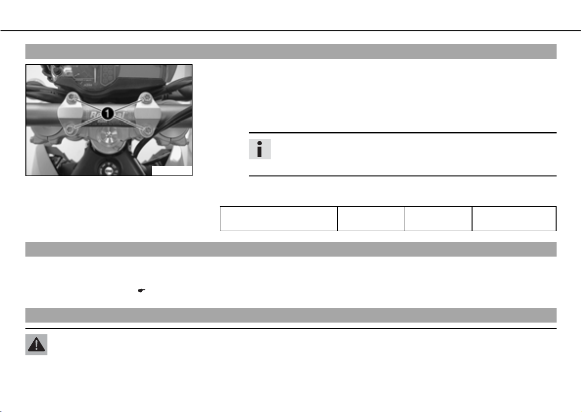
ದ Loosen screwb.
ದ Move the handlebar to the desired position and slightly tichten the screws.
ದ Move the handlebar carefully in both directions as far as it will go.
» If the handlebar instruments touch the fuel tank:
ದ Correct the handlebar angle.
Info
The distance between the handlebar support and the handlebar clamp
100279-10
ದ Fully tighten screwb
Specification
Screw, handlebar clamp M8 20bNm
Checking chain dirt
ದ Check the chain for coarse dirt accumulation.
» If the chain is very dirty:
ದ Clean the chain. ( P. 70)
must be the same at the front and rear.
.
(14.8blbfbft)
Loctite
®
243™
Cleaning the chain
Warning
Danger of accidentsಘOil or grease on the tires reduces their grip.
ದ Remove oil and grease with a suitable cleaning material.
Page 73
MAINTENANCE WORK ON CHASSIS AND ENGINE 71
Warning
Danger of accidentsಘReduced braking due to oil or grease on the brake discs.
ದ Always keep the brake discs free of oil and grease, and clean them with brake cleaner when necessary.
Warning
Environmental hazardಘProblem materials cause environmental damage.
ದ Dispose of oil, grease, filters, fuel, cleaning substances, brake fluid, batteries, etc. according to regulations.
Info
The service life of the chain depends largely on its maintenance.
ದ Clean the chain regularly.
ದ Rinse off loose dirt with a soft jet of water.
ದ Remove old grease remains with chain cleaner.
Chain cleaner ( P. 168)
ದ After drying, apply chain spray.
Onroad chain spray ( P. 168)
Checking the chain tension
Warning
Danger of accidentsಘDanger caused by incorrect chain tension.
ದ If the chain tension is too high, the components of the secondary power train (chain, engine sprocket, rear sprocket, bearings
in transmission and rear wheel) are under additional load. Apart from premature wear, in extreme cases the chain can rupture
or the countershaft of the transmission can break. On the other hand, if the chain is loose, it can fall off the engine sprocket or
the rear sprocket and block the rear wheel or damage the engine. Check for correct chain tension and adjust if necessary.
Page 74
MAINTENANCE WORK ON CHASSIS AND ENGINE 72
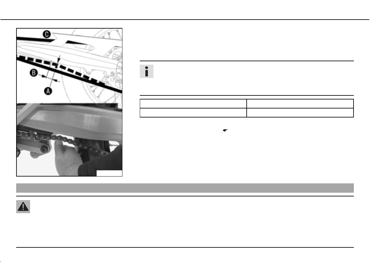
ದ Lean the motorcycle on the side stand.
ದ Shift gear to neutral.
Adjusting chain tension
100249-10
ದ Push the chain upward at a distanceb
chain tensionb
.
Info
The upper chain sectionb must be taut.
Chain wear is not always even, so you should repeat this measurement at different chain positions.
Chain tension 5bmm (0.2bin)
Distance to chain sliding guard 30bmm (1.18bin)
» If the chain tension does not meet specifications:
ದ Adjust the chain tension. ( P. 72)
from the chain sliding guard and determine the
Warning
Danger of accidentsಘDanger caused by incorrect chain tension.
ದ If the chain tension is too high, the components of the secondary power train (chain, engine sprocket, rear sprocket, bearings
in transmission and rear wheel) are under additional load. Apart from premature wear, in extreme cases the chain can rupture
or the countershaft of the transmission can break. On the other hand, if the chain is loose, it can fall off the engine sprocket or
the rear sprocket and block the rear wheel or damage the engine. Check for correct chain tension and adjust if necessary.
Page 75
MAINTENANCE WORK ON CHASSIS AND ENGINE 73
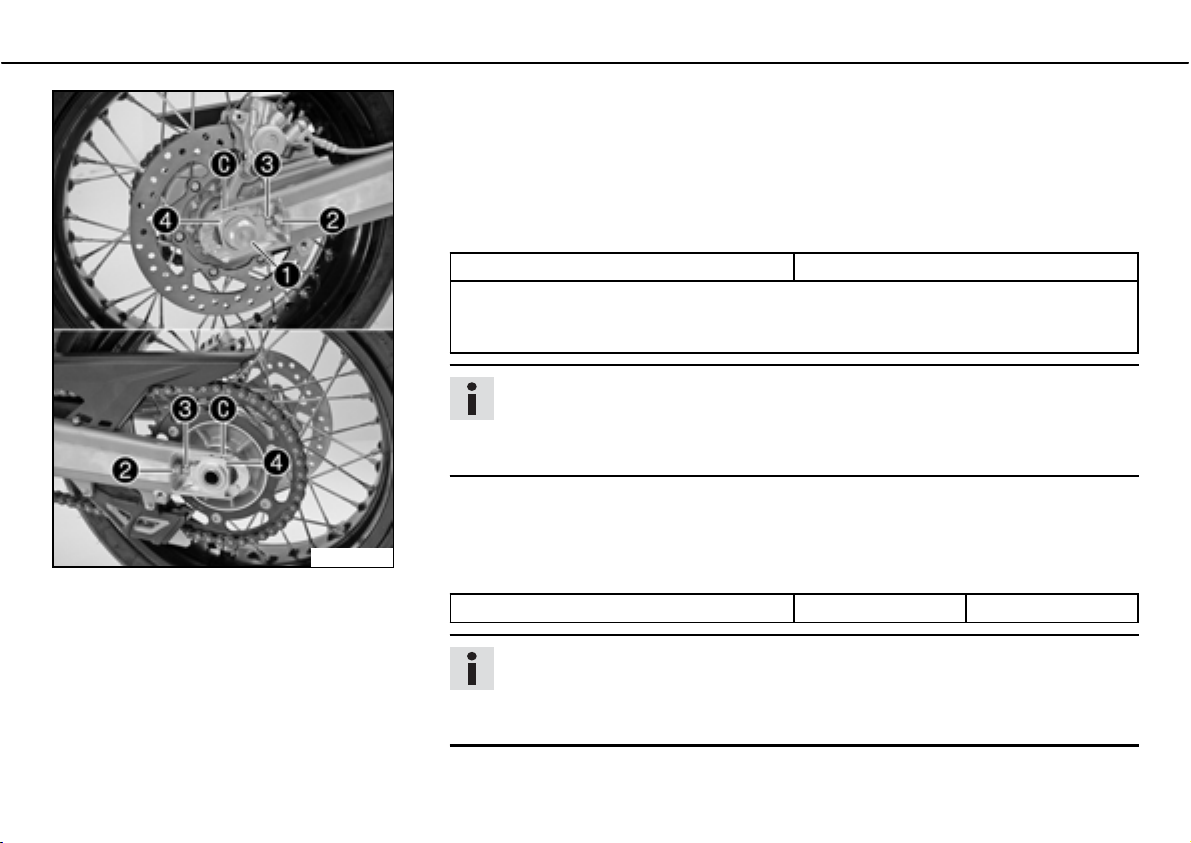
ದ Lean the motorcycle on the side stand.
ದ Shift gear to neutral.
ದ Loosen nutb
ದ Loosen nutsb
ದ Adjust the chain tension by turning the adjusting screwsb
Specification
Chain tension 5bmm (0.2bin)
Turn the adjusting screwsb
chain adjustersb
rear wheel is then correctly aligned.
.
.
left and right.
left and right so that the markings on the left and right
are in the same position relative to the reference marksb. The
Info
The upper chain section must be taut.
Chain wear is not always even, so you should repeat this measurement at different chain positions.
600597-10
ದ Tighten nutsb
ದ Make sure that the chain adjustersb
ದ Tighten nutb
Specification
Nut, rear wheel spindle M25x1.5 90bNm (66.4blbfbft)
.
are fitted correctly on the adjusting screwsb.
.
Info
The wide adjustment range of the chain adjusters (32 mm) enables different
secondary transmissions with the same chain length.
The chain adjustersb
can be turned by 180°.
Page 76
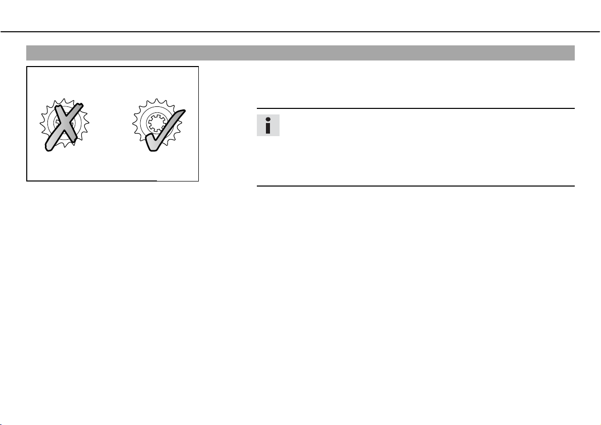
MAINTENANCE WORK ON CHASSIS AND ENGINE 74
Checking rear sprocket / engine sprocket for wear
ದ Check rear sprocket / engine sprocket for wear.
» If the rear sprocket / engine sprocket are worn:
ದ Replace rear sprocket / engine sprocket.
Info
The engine sprocket, rear sprocket and chain should always be replaced
together.
For safety reasons, the chain has no chain joint. Always have the chain
replaced in an authorized KTM workshop, where the necessary chain
100132-10
ದ Check chain guides for tightness and wear.
rivet tool is available.
Page 77
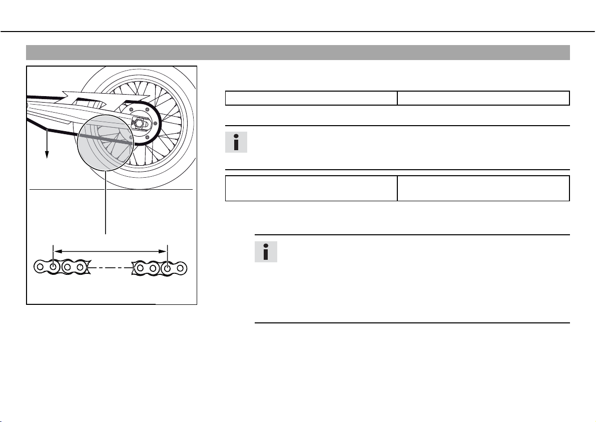
MAINTENANCE WORK ON CHASSIS AND ENGINE 75
Checking chain wear
ದ Shift into neutral, pull the lower chain section with the specified weightb.
Specification
Weight of chain wear measurement 15bkg (33blb.)
A
B
1 2 3 16 17 18
400409-10
ದ Measure the distanceb
Info
Chain wear is not always even, so you should repeat this measurement at different chain positions.
Maximum distanceb
chain section
» If the distanceb
ದ Have the chain changed.
is greater than the specified measurement:
Info
When the chain is replaced, the rear sprocket and engine sprocket
should also be changed.
New chains wear out faster on old, worn sprockets.
For safety reasons, the chain has no chain joint. Always have the chain
changed in an authorized KTM workshop, where the necessary tool is
available.
of 18 chain links in the lower chain section.
at the longest
272bmm (10.71bin)
Page 78
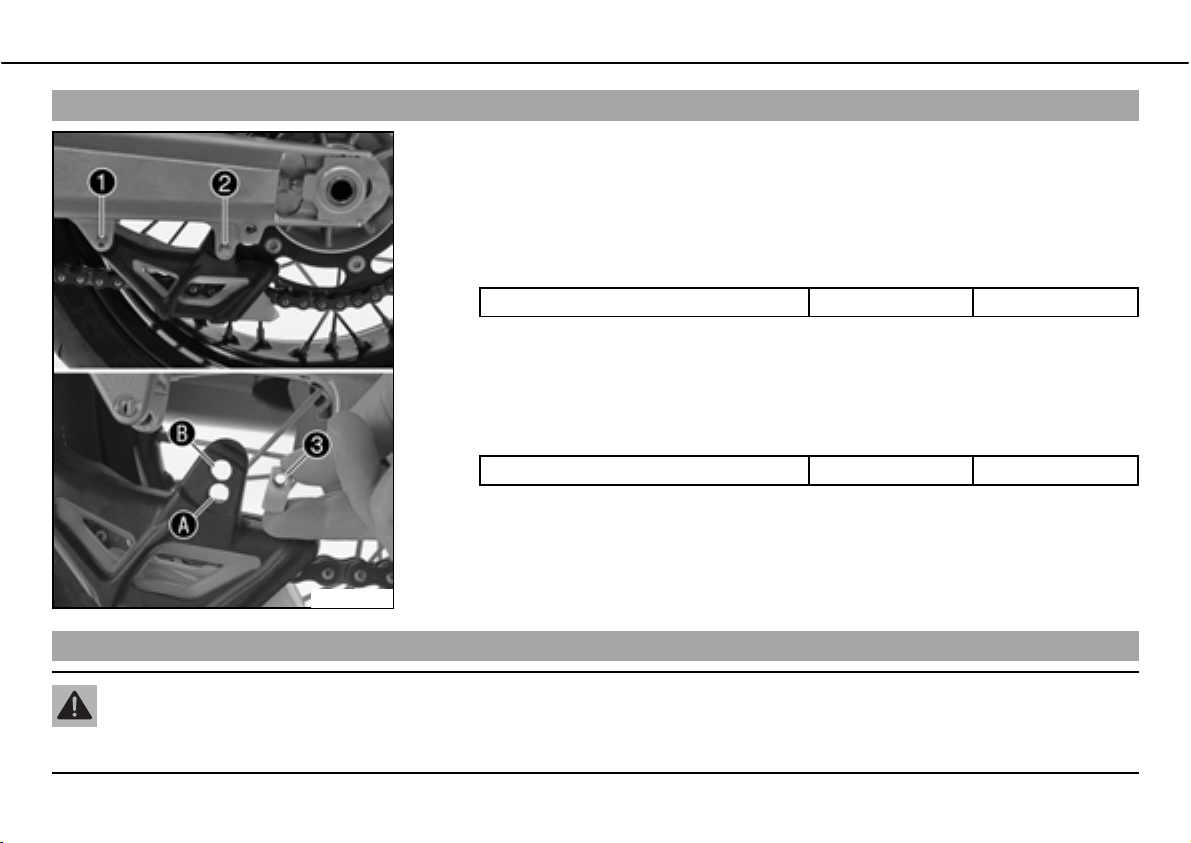
MAINTENANCE WORK ON CHASSIS AND ENGINE 76
Adjusting chain guidebx
ದ Remove screwsb andb. Take off the chain guide.
Conditions
Number of teeth: ืb44bteeth
ದ Insert nutb
ದ Mount and tighten screwsb
Specification
Remaining screws, chassis M6 10bNm (7.4blbfbft)
Conditions
Number of teeth: ุb45bteeth
ದ Insert nutb
ದ Mount and tighten screwsb
Specification
Remaining screws, chassis M6 10bNm (7.4blbfbft)
600635-10
in holeb. Position the chain guide.
andb.
in holeb. Position the chain guide.
andb.
Checking brake discs
Warning
Danger of accidentsಘReduced braking due to worn brake discs.
ದ Worn brake discs should be replaced immediately in an authorized KTM workshop.
Page 79
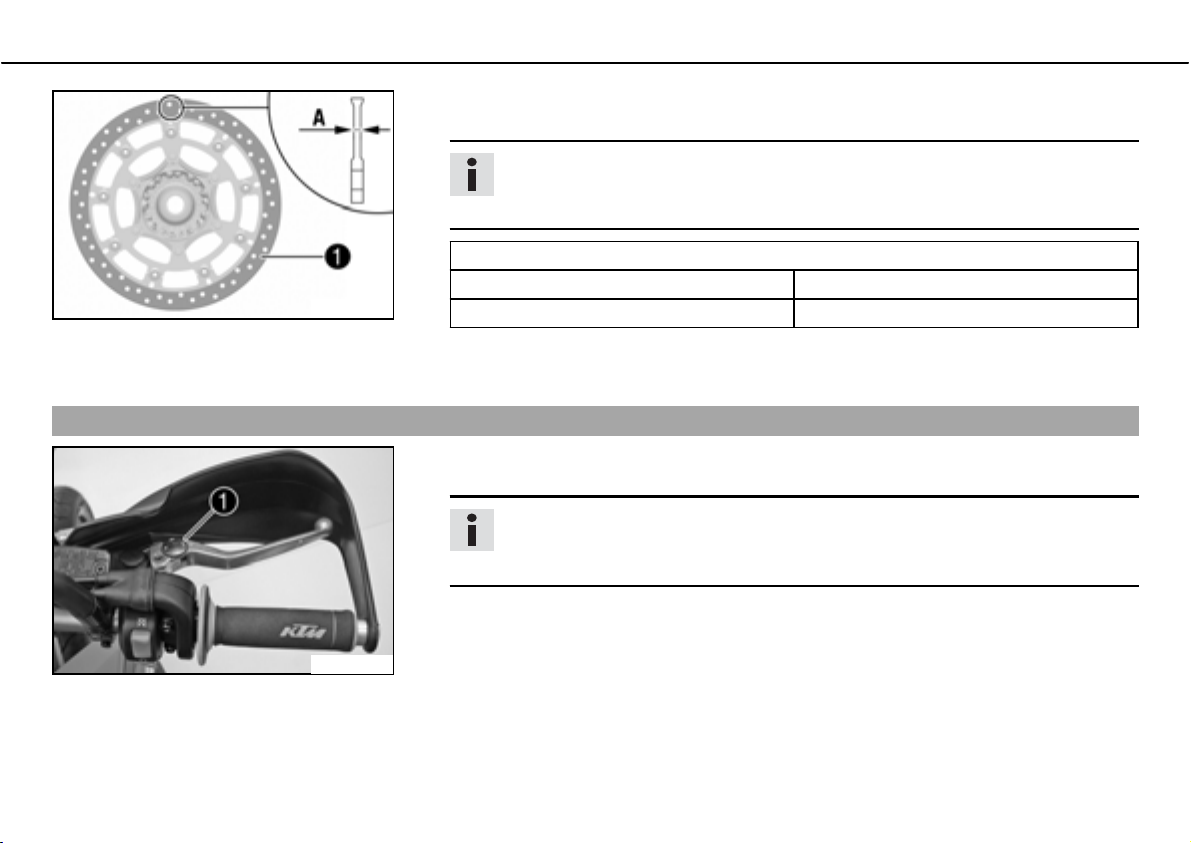
MAINTENANCE WORK ON CHASSIS AND ENGINE 77
ದ Check the thickness of the front and rear brake discs at several places on the disc to
100135-10
Adjusting basic position of handbrake lever
ದ Adjust the basic setting of the handbrake lever to your hand size by turning adjusting
see if it conforms to measurementb
Info
Wear reduces the thickness of the brake disc around the area used by the brake
.
linings.
Wear limit of brake discs
front 4.0bmm (0.157bin)
Rear 4.5bmm (0.177bin)
» If the brake disc thickness is less than the specified value:
ದ Change the brake disc.
wheelb
.
Info
Pull the brake lever forwards and turn the adjusting wheel.
Do not make any adjustments while riding!
.
600598-10
Page 80
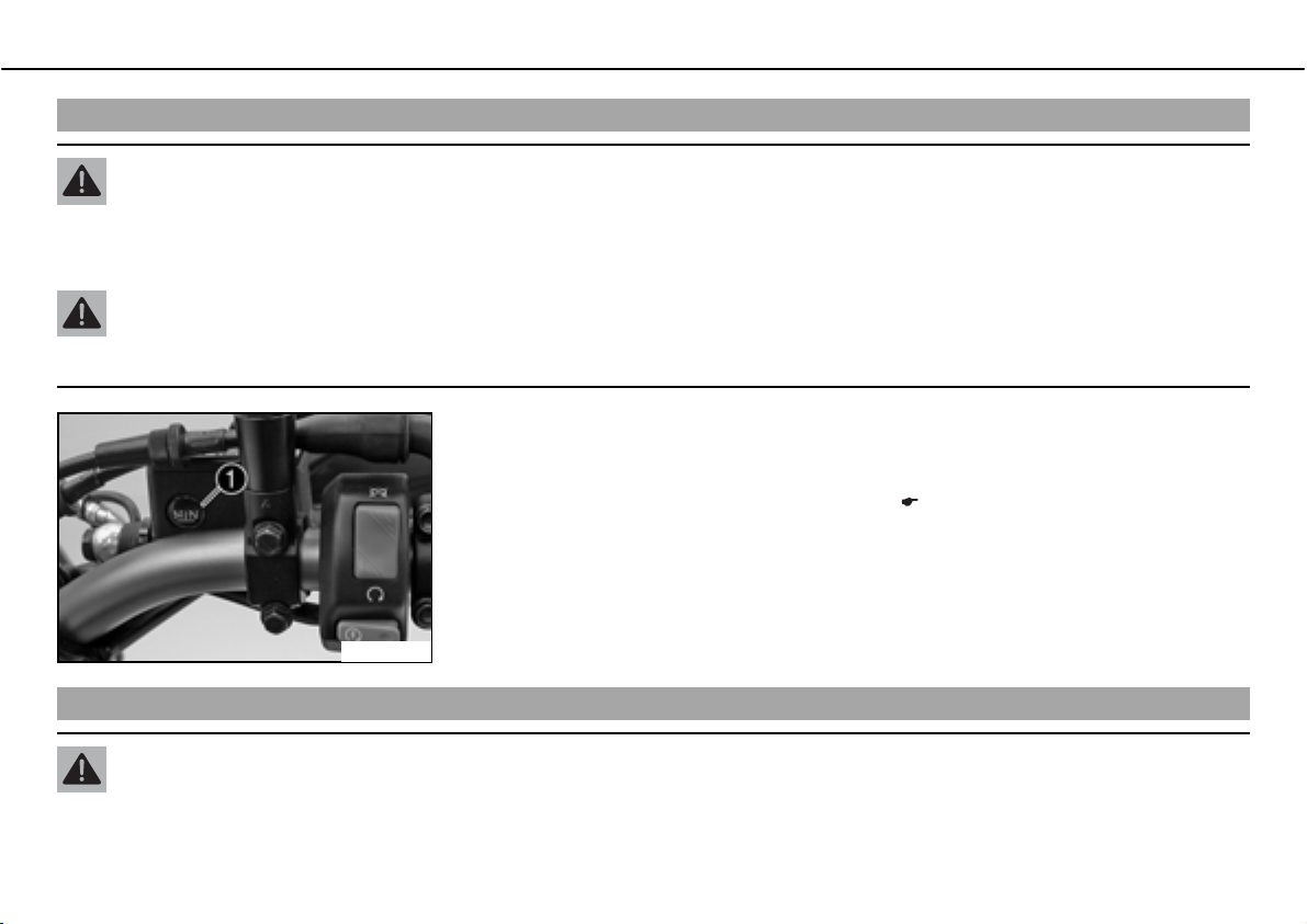
MAINTENANCE WORK ON CHASSIS AND ENGINE 78
Checking front brake fluid level
Warning
Danger of accidentsಘBrake system failure.
ದ MINIf the brake fluid level falls below the MIN mark, this indicates a leakage in the brake system or worn-out brake linings.
Have the brake system checked in an authorized KTM workshop, and do not ride any further.
Warning
Danger of accidentsಘReduced braking due to old brake fluid.
ದ Have the front and rear brake fluid replaced according to the service plan in an authorized KTM workshop.
ದ The brake fluid level must not fall below the center of the level viewerb when the
brake fluid reservoir is vertical.
» If the brake fluid level is lower than the center of the level viewer:
ದ
Add brake fluid for the front brake.b
600603-10
x ( P. 78)
Adding brake fluid for front brakebx
Warning
Danger of accidentsಘBrake system failure.
ದ MINIf the brake fluid level falls below the MIN mark, this indicates a leakage in the brake system or worn-out brake linings.
Have the brake system checked in an authorized KTM workshop, and do not ride any further.
Page 81
MAINTENANCE WORK ON CHASSIS AND ENGINE 79
Warning
Skin irritationsಘBrake fluid can cause skin irritation on contact.
ದ Avoid contact with skin and eyes, and keep out of the reach of children.
ದ If brake fluid gets into your eyes, rinse thoroughly with water and contact a doctor immediately.
Warning
Danger of accidentsಘReduced braking due to old brake fluid.
ದ Have the front and rear brake fluid replaced according to the service plan in an authorized KTM workshop.
Warning
Environmental hazardಘProblem materials cause environmental damage.
ದ Dispose of oil, grease, filters, fuel, cleaning substances, brake fluid, batteries, etc. according to regulations.
Info
Never user DOTb5 brake fluid! It is based on silicone oil and is colored purple. Oil seals and brake lines are not designed for DOTb5
brake fluid.
Avoid contact between brake fluid and painted parts. Brake fluid attacks paint!
Use only clean brake fluid from a sealed container!
ದ Move the brake fluid reservoir mounted on the handlebar to a horizontal position.
Page 82
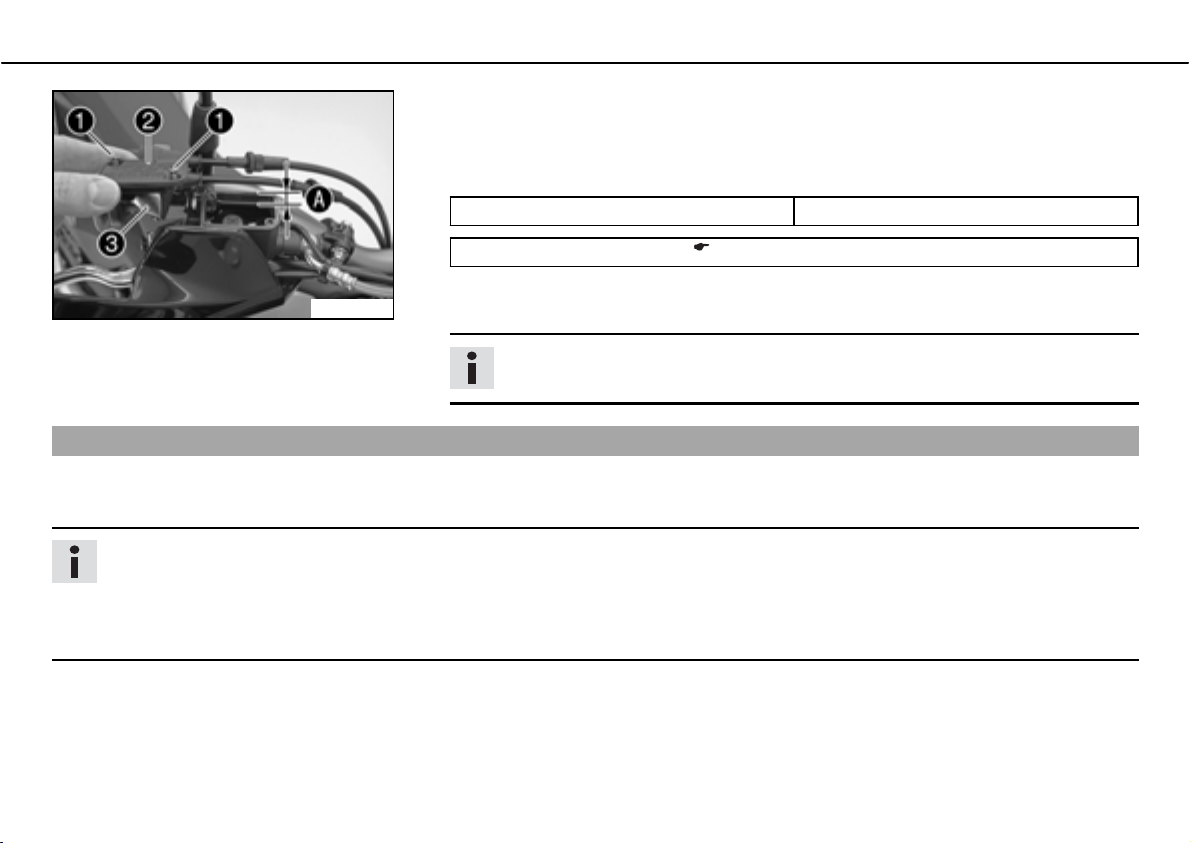
MAINTENANCE WORK ON CHASSIS AND ENGINE 80
ದ Remove screwsb.
ದ Remove coverb
ದ Add brake fluid to levelb
Specification
Measurement ofb
Brake fluid DOTb4b/bDOTb5.1 ( P. 165)
ದ Check parts for damage and wear. Replace damaged or worn parts.
100254-10
Brake linings
The brake linings fitted by KTM were tested over long periods and ensure optimal braking properties. The type names of brake pads are
entered in the homologation documents.
ದ Position the cover with the membrane. Mount and tighten screws.
Info
Brake linings available from accessory suppliers are often not tested and approved for use on KTM vehicles. The construction and
friction factor of the brake linings and therefore the brake power can differ considerably from the original KTM brake linings. If
brake linings are used that differ from the originals, there is no guarantee that they comply with the original license. The vehicle
no longer corresponds to the condition at delivery, and the warranty is no longer valid.
with membraneb.
.
5bmm (0.2bin)
Info
Clean up overflowed or spilt brake fluid immediately with water.
Page 83
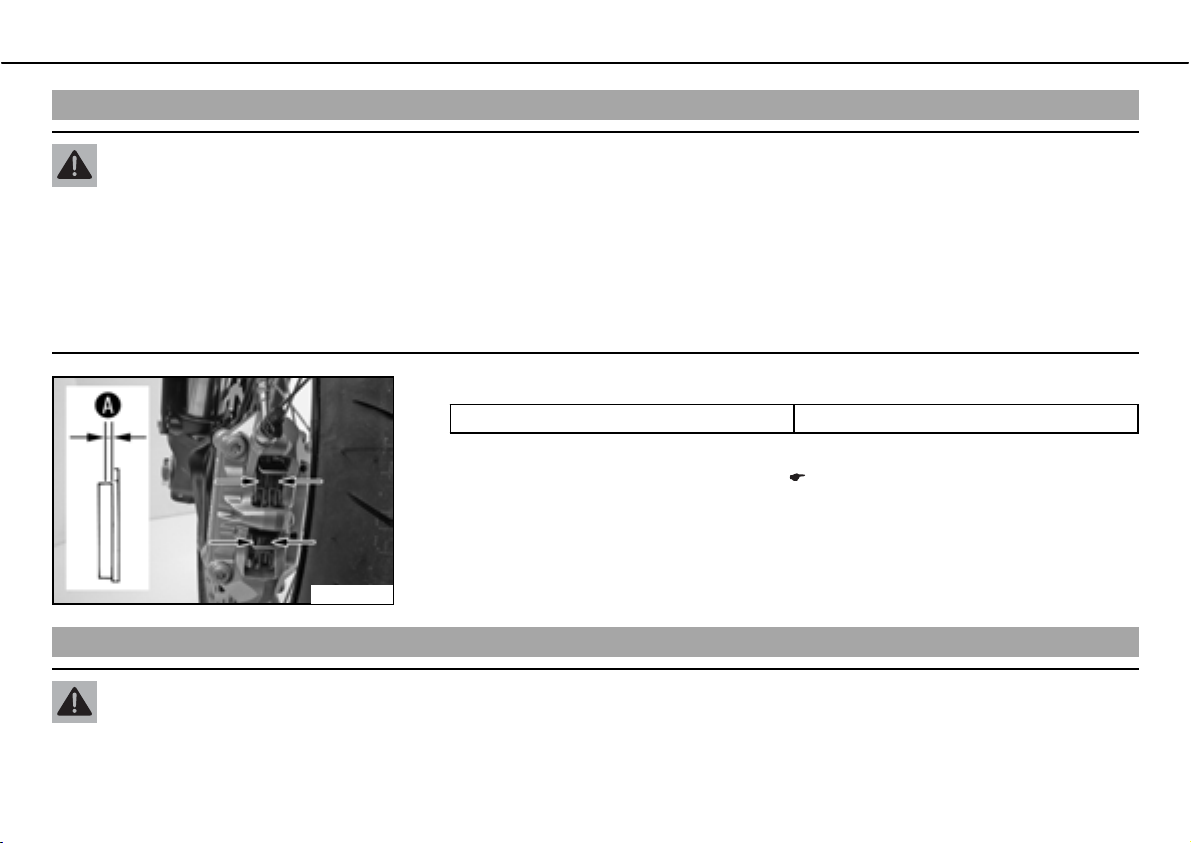
MAINTENANCE WORK ON CHASSIS AND ENGINE 81
Checking the front brake linings
Warning
Danger of accidentsಘReduced braking due to worn brake linings.
ದ Worn brake linings should be replaced immediately in an authorized KTM workshop.
Note
Danger of accidentsಘReduced braking due to damaged brake discs.
ದ If the brake linings are not changed in time, the steel brake lining carriers grind on the brake disc. The braking effect is greatly
reduced and the brake discs are destroyed.
ದ Check the brake linings for minimum thicknessb.
600625-10
Changing the front brake liningsbx
Minimum thicknessb
» If the minimum thickness is less than specified:
ದ
Change the front brake linings.b
ุb1bmm (ุb0.04bin)
Warning
Danger of accidentsಘImproper brake maintenance and repair.
ದ Always have your brake system maintained and repaired in an authorized KTM workshop.
x ( P. 81)
Page 84
MAINTENANCE WORK ON CHASSIS AND ENGINE 82
Warning
Skin irritationsಘBrake fluid can cause skin irritation on contact.
ದ Avoid contact with skin and eyes, and keep out of the reach of children.
ದ If brake fluid gets into your eyes, rinse thoroughly with water and contact a doctor immediately.
Warning
Danger of accidentsಘReduced braking due to old brake fluid.
ದ Have the front and rear brake fluid replaced according to the service plan in an authorized KTM workshop.
Warning
Danger of accidentsಘReduced braking due to oil or grease on the brake discs.
ದ Always keep the brake discs free of oil and grease, and clean them with brake cleaner when necessary.
Warning
Danger of accidentsಘReduced braking due to use of non-approved brake linings.
ದ Brake linings available from accessory suppliers are often not tested and approved for use on KTM vehicles. The construction
and friction factor of the brake linings and therefore the brake power can differ considerably from the original KTM brake linings. If brake linings are used that differ from the originals, there is no guarantee that they comply with the original license.
The vehicle no longer corresponds to the condition at delivery, and the warranty is no longer valid.
Warning
Environmental hazardಘProblem materials cause environmental damage.
ದ Dispose of oil, grease, filters, fuel, cleaning substances, brake fluid, batteries, etc. according to regulations.
Info
Never user DOTb5 brake fluid! It is based on silicone oil and is purple in color. Oil seals and brake lines are not designed for DOTb5
brake fluid.
Avoid contact between brake fluid and painted parts. Brake fluid attacks paint!
Use only clean brake fluid from a sealed container!
Page 85
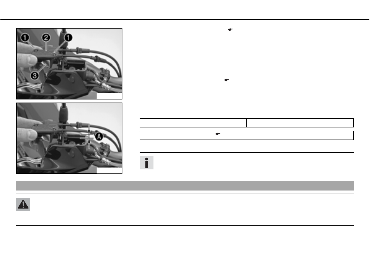
MAINTENANCE WORK ON CHASSIS AND ENGINE 83
ದ
100254-11
100254-12
Removing front brake liningsbx
Remove the front brake linings.b
ದ Move the brake fluid reservoir mounted on the handlebar to a horizontal position.
ದ Remove screwsb
ದ Remove coverb
ದ Press the brake piston back to its basic position and make sure that no brake fluid over-
flows from the reservoir.
ದ
Mount the front brake linings.b
ದ Check parts for damage and wear. Replace damaged or worn parts.
ದ Adjust the brake fluid level to levelb.
Specification
Measurement ofb
Brake fluid DOTb4b/bDOTb5.1 ( P. 165)
ದ Position the cover with the membrane. Mount and tighten the screws.
.
with membraneb.
5bmm (0.2bin)
Info
Clean up overflowed or spilt brake fluid immediately with water.
x ( P. 83)
x ( P. 84)
Warning
Danger of accidentsಘImproper brake maintenance and repair.
ದ Always have your brake system maintained and repaired in an authorized KTM workshop.
Page 86
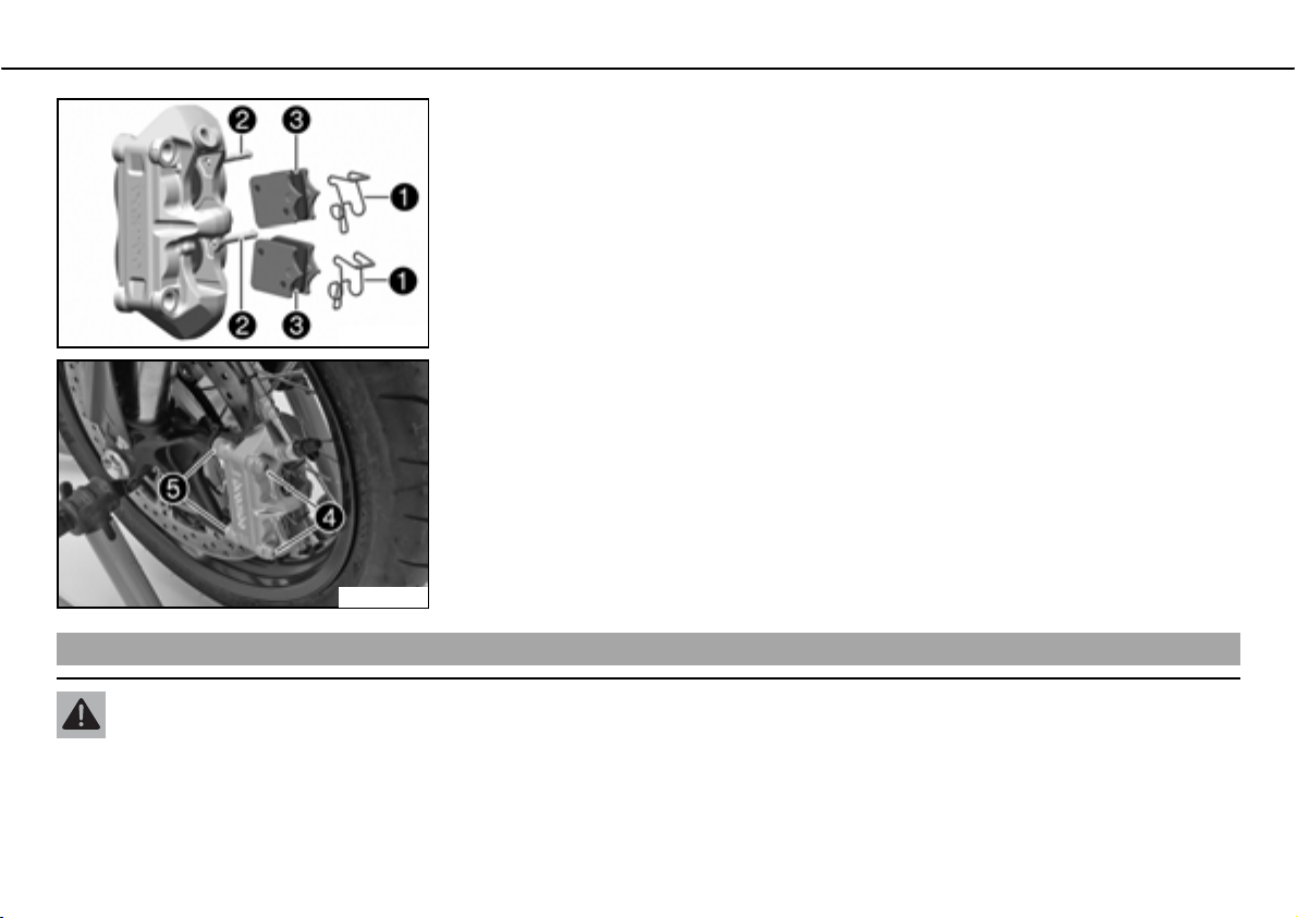
MAINTENANCE WORK ON CHASSIS AND ENGINE 84
ದ Press the spring hanger of the springb forwards and withdraw the boltb.
ದ Take off the springsb
400421-11
ದ Remove screwb and spacing sleeveb. Remove the brake caliper.
ದ Clean the brake caliper.
600621-12
Mounting front brake liningsbx
. Remove brake liningsb.
Warning
Danger of accidentsಘReduced braking due to oil or grease on the brake discs.
ದ Always keep the brake discs free of oil and grease, and clean them with brake cleaner when necessary.
Page 87
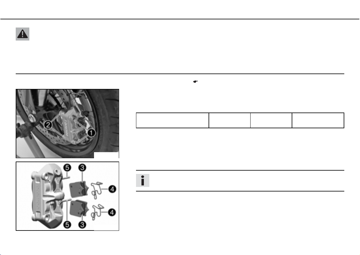
MAINTENANCE WORK ON CHASSIS AND ENGINE 85
Warning
Danger of accidentsಘReduced braking due to use of non-approved brake linings.
ದ Brake linings available from accessory suppliers are often not tested and approved for use on KTM vehicles. The construction
and friction factor of the brake linings and therefore the brake power can differ considerably from the original KTM brake linings. If brake linings are used that differ from the originals, there is no guarantee that they comply with the original license.
The vehicle no longer corresponds to the condition at delivery, and the warranty is no longer valid.
ದ Check the brake discs. ( P. 76)
ದ Check parts for damage and wear. Replace damaged or worn parts.
ದ Position the brake caliper. Mount and tighten screwsb
Specification
Screw, front brake caliper M10x1.25 45bNm
600621-10
ದ Insert brake linings . Position the springsb and mount the boltsb.
Info
The spring hanger of the springsb must be positioned upwards.
with spacing sleevesb.
Loctite
(33.2blbfbft)
®
243™
400421-12
ದ Operate the hand brake lever repeatedly until the brake linings lie on the brake disc and
there is a tight spot.
Page 88
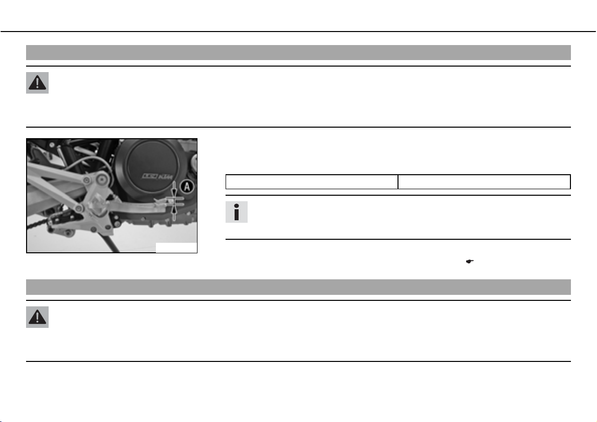
MAINTENANCE WORK ON CHASSIS AND ENGINE 86
Checking free play of foot brake lever
Warning
Danger of accidentsಘBrake system failure.
ದ If there is no free travel on the foot brake pedal, pressure builds up on the rear brake in the brake system. The rear brake can
fail due to overheating. Adjust free travel on foot brake pedal according to specifications.
ದ Move the foot brake lever back and forth between the end stop and the contact to the
foot brake cylinder piston and check free travelb
Specification
Free play at foot brake lever 3… 5bmm (0.12… 0.2bin)
Info
You will know that contact has been made with the foot brake cylinder piston
when there is increased resistance when you activate the foot brake pedal.
.
600599-10
Adjusting basic position of foot brake pedalbx
» If the free travel does not meet specifications:
ದ
Adjust the basic position of the foot brake pedal.b
x ( P. 86)
Warning
Danger of accidentsಘBrake system failure.
ದ If there is no free travel on the foot brake pedal, pressure builds up on the rear brake in the brake system. The rear brake can
fail due to overheating. Adjust free travel on foot brake pedal according to specifications.
Page 89
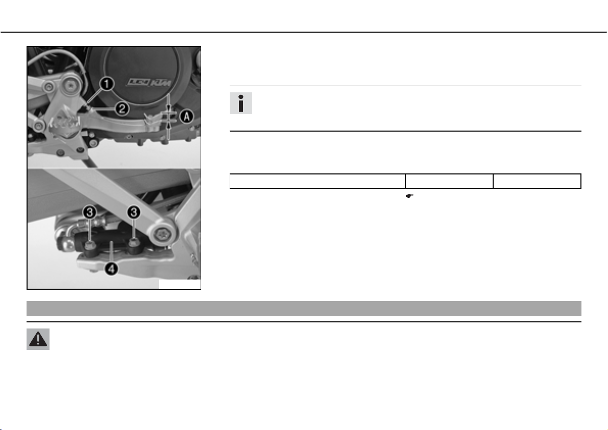
MAINTENANCE WORK ON CHASSIS AND ENGINE 87
ದ Remove screw connectionb on foot brake cylinderb.
ದ To adjust the basic position of the foot brake pedal as needed, loosen nutb
accordingly.
screwb
Info
The range of adjustment is limited. The screw must be screwed into the footrest
bracket by at least four turns.
and turn
600639-10
Checking rear brake fluid level
ದ Position foot brake cylinderb
Hold screwsb
Specification
Nut, foot brake cylinder screw M6 10bNm (7.4blbfbft)
ದ Check the free play of the foot brake lever. ( P. 86)
ದ Tighten nutb
in place and tighten the nuts.
.
so that the foot brake pedal has the necessary free travel.
Warning
Danger of accidentsಘBrake system failure.
ದ MINIf the brake fluid level falls below the MIN mark, this indicates a leakage in the brake system or worn-out brake linings.
Have the brake system checked in an authorized KTM workshop, and do not ride any further.
Page 90
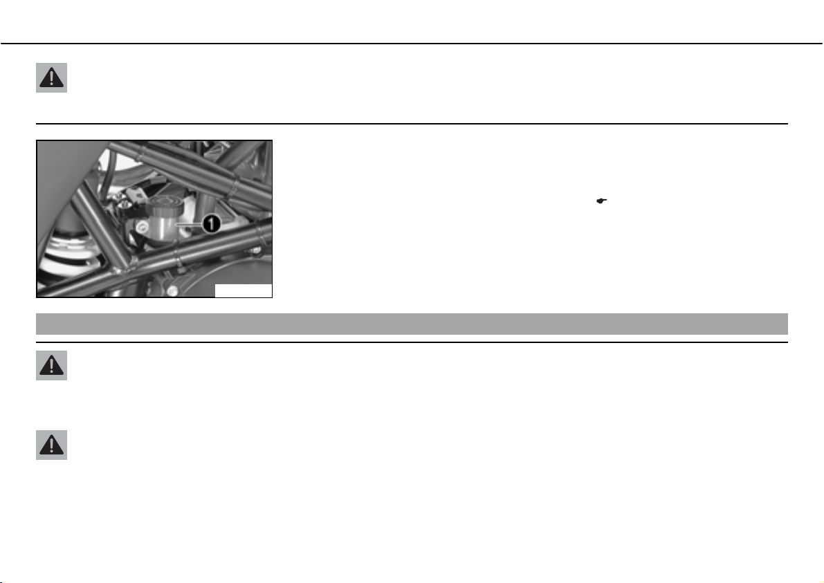
MAINTENANCE WORK ON CHASSIS AND ENGINE 88
Warning
Danger of accidentsಘReduced braking due to old brake fluid.
ದ Have the front and rear brake fluid replaced according to the service plan in an authorized KTM workshop.
ದ Stand the vehicle upright.
ದ Check the brake fluid level in the brake fluid reservoir.
» If the fluid level reaches thebMINbmarkingb
ದ
Top up the brake fluid of the rear brake.b
100258-10
Topping up brake fluid of rear brakebx
Warning
Danger of accidentsಘBrake system failure.
ದ MINIf the brake fluid level falls below the MIN mark, this indicates a leakage in the brake system or worn-out brake linings.
Have the brake system checked in an authorized KTM workshop, and do not ride any further.
Warning
Skin irritationsಘBrake fluid can cause skin irritation on contact.
ದ Avoid contact with skin and eyes, and keep out of the reach of children.
ದ If brake fluid gets into your eyes, rinse thoroughly with water and contact a doctor immediately.
:
x ( P. 88)
Page 91
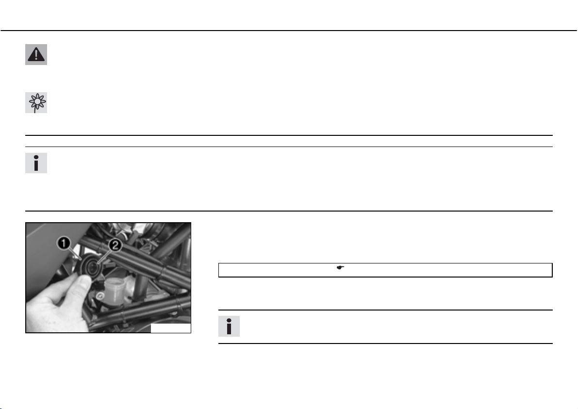
MAINTENANCE WORK ON CHASSIS AND ENGINE 89
Warning
Danger of accidentsಘReduced braking due to old brake fluid.
ದ Have the front and rear brake fluid replaced according to the service plan in an authorized KTM workshop.
Warning
Environmental hazardಘProblem materials cause environmental damage.
ದ Dispose of oil, grease, filters, fuel, cleaning substances, brake fluid, batteries, etc. according to regulations.
Info
Never user DOTb5 brake fluid! This is based on silicone oil and is colored purple. Oil seals and brake lines are not designed for
DOTb5 brake fluid.
Avoid contact between brake fluid and painted parts. Brake fluid attacks paint!
Use only clean brake fluid from a sealed container!
ದ Stand the vehicle upright.
ದ Remove screw coverb
ದ Top up the brake fluid tobMAX level.
Brake fluid DOTb4b/bDOTb5.1 ( P. 165)
ದ Check parts for damage and wear. Replace damaged or worn parts.
ದ Refit screw with membrane.
with membraneb.
100259-10
Info
Clean up overflowed or spilt brake fluid immediately with water.
Page 92
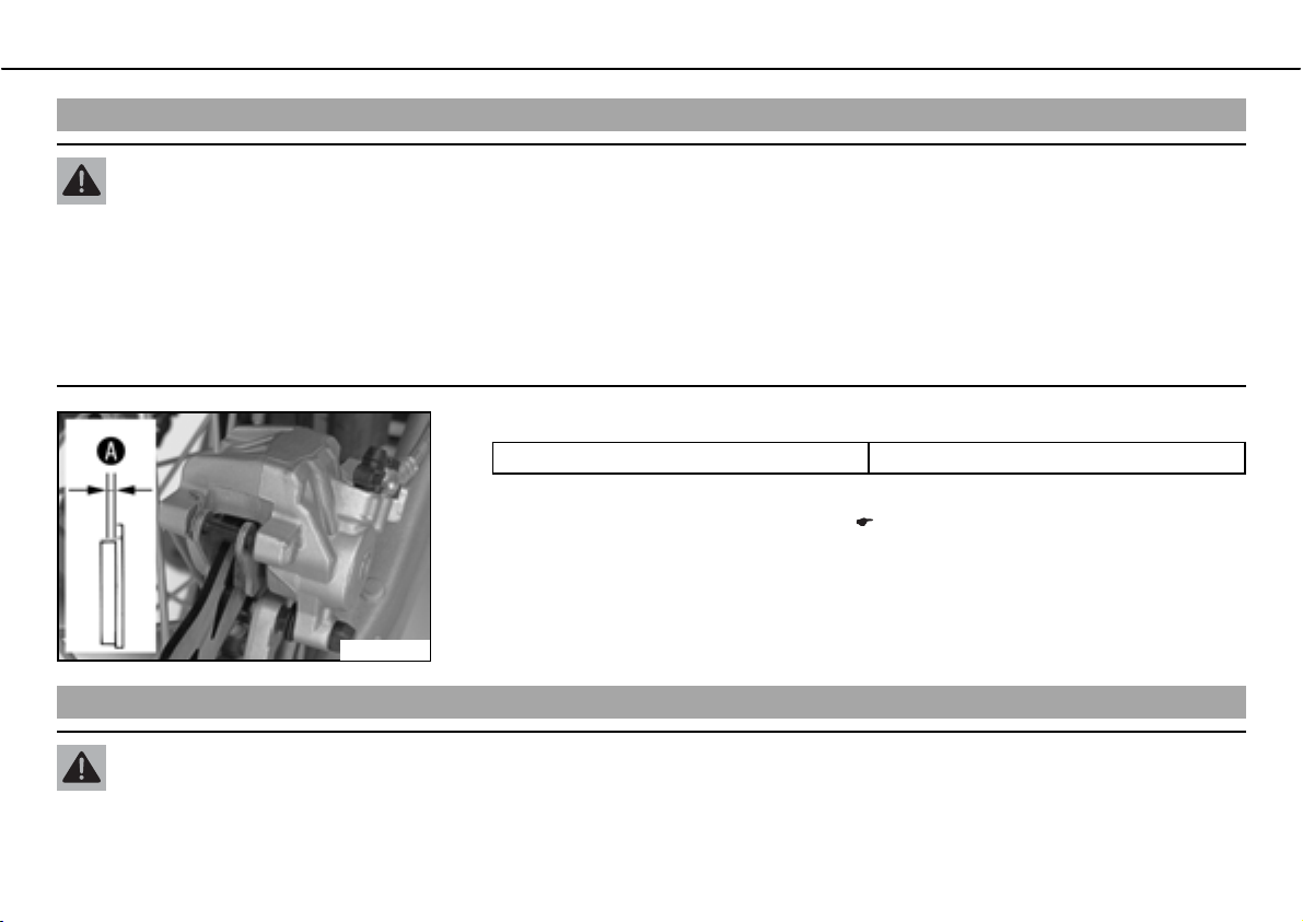
MAINTENANCE WORK ON CHASSIS AND ENGINE 90
Checking the rear brake linings
Warning
Danger of accidentsಘReduced braking due to worn brake linings.
ದ Worn brake linings should be replaced immediately in an authorized KTM workshop.
Note
Danger of accidentsಘReduced braking due to damaged brake discs.
ದ If the brake linings are not changed in time, the steel brake lining carriers grind on the brake disc. The braking effect is greatly
reduced and the brake discs are destroyed.
ದ Check the brake linings for minimum thicknessb.
100260-10
Changing rear brake liningsbx
Minimum thicknessb
» If the minimum thickness is less than specified:
ದ
Change the rear brake linings.b
ุb1bmm (ุb0.04bin)
Warning
Danger of accidentsಘImproper brake maintenance and repair.
ದ Always have your brake system maintained and repaired in an authorized KTM workshop.
x ( P. 90)
Page 93
MAINTENANCE WORK ON CHASSIS AND ENGINE 91
Warning
Skin irritationsಘBrake fluid can cause skin irritation on contact.
ದ Avoid contact with skin and eyes, and keep out of the reach of children.
ದ If brake fluid gets into your eyes, rinse thoroughly with water and contact a doctor immediately.
Warning
Danger of accidentsಘReduced braking due to old brake fluid.
ದ Have the front and rear brake fluid replaced according to the service plan in an authorized KTM workshop.
Warning
Danger of accidentsಘReduced braking due to oil or grease on the brake discs.
ದ Always keep the brake discs free of oil and grease, and clean them with brake cleaner when necessary.
Warning
Danger of accidentsಘReduced braking due to use of non-approved brake linings.
ದ Brake linings available from accessory suppliers are often not tested and approved for use on KTM vehicles. The construction
and friction factor of the brake linings and therefore the brake power can differ considerably from the original KTM brake linings. If brake linings are used that differ from the originals, there is no guarantee that they comply with the original license.
The vehicle no longer corresponds to the condition at delivery, and the warranty is no longer valid.
Warning
Environmental hazardಘProblem materials cause environmental damage.
ದ Dispose of oil, grease, filters, fuel, cleaning substances, brake fluid, batteries, etc. according to regulations.
Info
Never user DOTb5 brake fluid! This is based on silicone oil and is colored purple. Oil seals and brake lines are not designed for
DOTb5 brake fluid.
Avoid contact between brake fluid and painted parts. Brake fluid attacks paint!
Use only clean brake fluid from a sealed container!
Page 94
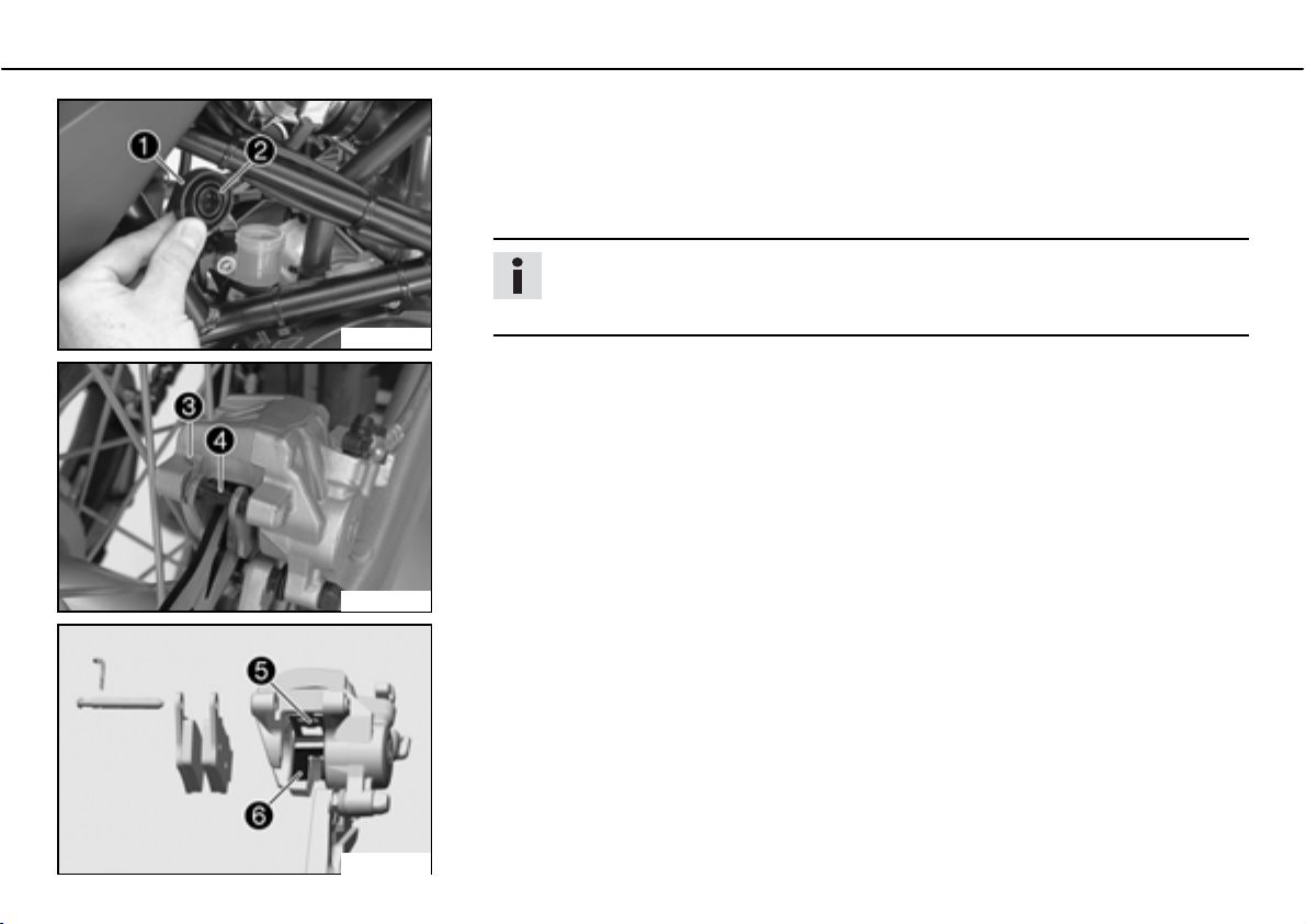
MAINTENANCE WORK ON CHASSIS AND ENGINE 92
ದ Stand the vehicle upright.
ದ Remove screw coverb
ದ Press the brake caliper by hand on to the brake disc in order to press back the brake
piston. Ensure that brake fluid does not overflow from the brake fluid reservoir and suction it off if necessary.
Info
Make sure when pushing back the brake piston that you do not press the brake
caliper against the spokes.
100259-10
ದ Remove split pinb, remove boltb toward the left by striking it and remove the brake
linings.
ದ Clean brake caliper and brake caliper support.
ದ Check parts for damage and wear. Replace damaged or worn parts.
100288-10
ದ Check that leaf springb in the brake caliper and sliding plateb in the brake caliper
support are seated correctly.
with membraneb.
400419-10
Page 95
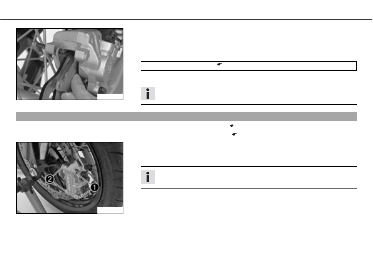
MAINTENANCE WORK ON CHASSIS AND ENGINE 93
ದ Insert the brake pads, insert the bolt and mount the split pin.
ದ Operate the foot brake lever repeatedly until the brake linings lie on the brake disc and
there is a tight spot.
ದ Adjust the brake fluid level to the MAXbmark.
Brake fluid DOTb4b/bDOTb5.1 ( P. 165)
ದ Refit screw with membrane.
Info
100289-01
Removing front wheelbx
ದ Jack up the rear of the motorcycle. ( P. 57)
ದ Jack up the front of the motorcycle. ( P. 56)
ದ Remove screwb and spacing sleeveb.
ದ Press back the brake linings with a light lateral tilting of the brake caliper on the brake
Clean up overflowed or spilt brake fluid immediately with water.
disc. Pull the brake caliper carefully back from the brake disc and hang it to one side.
Info
Do not pull the handbrake lever when the brake caliper is removed.
600621-10
Page 96
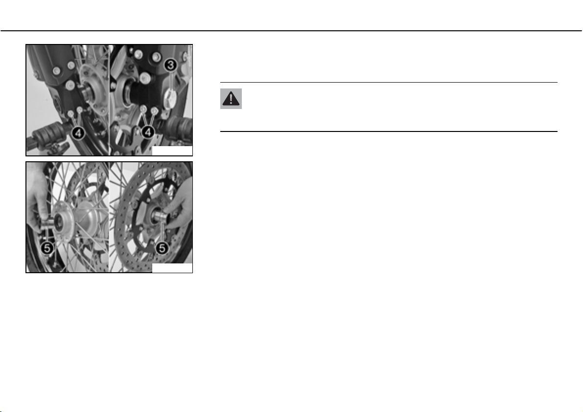
MAINTENANCE WORK ON CHASSIS AND ENGINE 94
ದ Loosed screwb and screwb.
ದ Screw out screwb
dle out of the fork stub. Remove screwb
Warning
Danger of accidentsಘReduced braking due to damaged brake discs.
ದ Always lay the wheel down in such a way that the brake disc is not damaged.
about 6 turns, press your hand on the screw to push the wheel spin-
.
600622-10
600626-11
ದ Holding the front wheel, withdraw the wheel spindle. Take the front wheel out of the
fork.
ದ Remove the spacing sleevesb.
Page 97
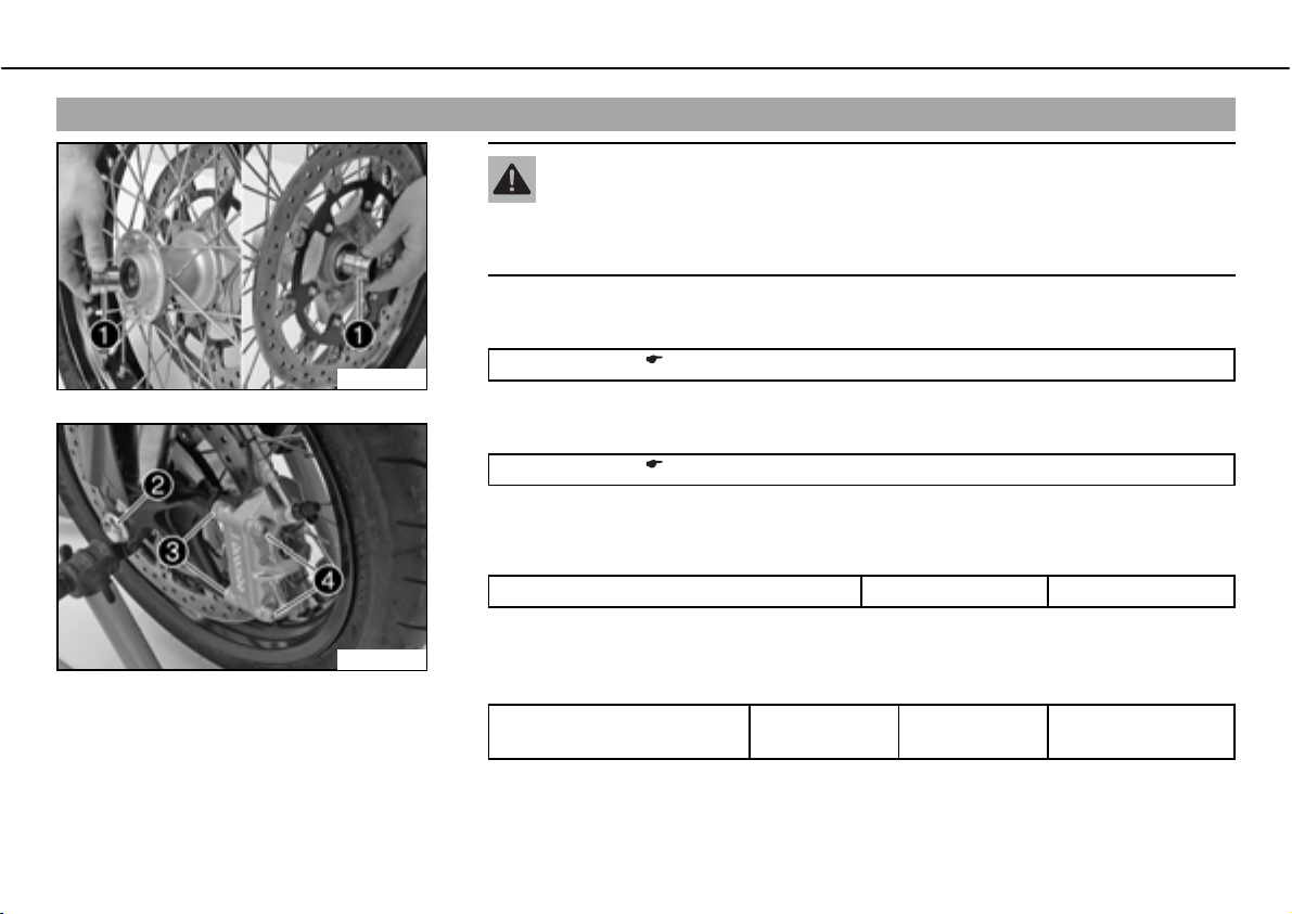
MAINTENANCE WORK ON CHASSIS AND ENGINE 95
Installing the front wheelbx
Warning
Danger of accidentsಘReduced braking due to oil or grease on the brake discs.
ದ Always keep the brake discs free of oil and grease, and clean them with
brake cleaner when necessary.
ದ Check parts for damage and wear. Replace damaged or worn parts.
ದ Clean and grease the shaft seal rings and bearing surface of spacing sleevesb
.
600626-10
600621-11
Long-life grease ( P. 168)
ದ Fit the spacing sleeves.
ದ Clean and grease the thread of the wheel spindle and screwb.
Long-life grease ( P. 168)
ದ Lift the front wheel into the fork, position it, and insert the wheel spindle. Mount and
tighten screwb
.
Specification
Screw, front wheel spindle M24x1.5 40bNm (29.5blbfbft)
ದ Position the brake caliper and check that the brake linings are seated correctly.
ದ Position the spacing sleevesb
. Mount and tighten screwsb.
Specification
Screw, front brake caliper M10x1.25 45bNm
Loctite
®
243™
(33.2blbfbft)
Page 98
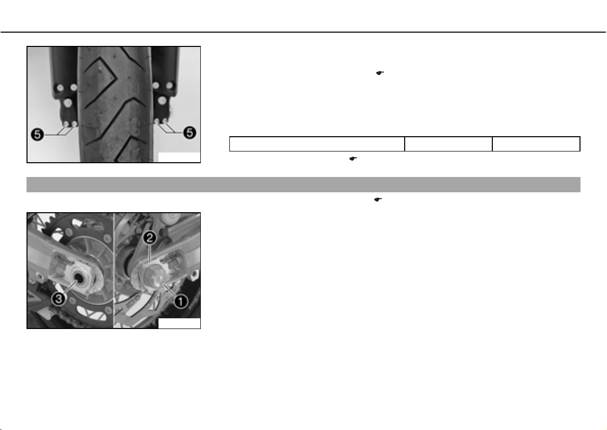
MAINTENANCE WORK ON CHASSIS AND ENGINE 96
ದ Operate the hand brake lever several times until the brake pads are lying correctly on
the brake disc.
ದ Take the front from the work stand. ( P. 56)
ದ Pull the front wheel brake and push down hard on the fork several times to align the
fork legs.
Removing rear wheelbx
600490-11
100267-10
ದ Fully tighten screwb
Specification
Screw, fork stub M8 15bNm (11.1blbfbft)
ದ Taking rear from work stand. ( P. 57)
ದ Jack up the rear of the motorcycle. ( P. 57)
ದ Press the brake caliper by hand on to the brake disc in order to press back the brake
piston.
ದ Remove nutb
ದ Holding the rear wheel, withdraw the wheel spindleb
.
. Remove chain adjusterb.
.
Page 99
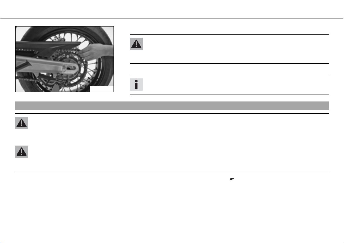
MAINTENANCE WORK ON CHASSIS AND ENGINE 97
ದ Push the rear wheel forwards as far as possible and take the chain off the rear sprocket.
Warning
Danger of accidentsಘReduced braking due to damaged brake discs.
ದ Always lay the wheel down in such a way that the brake disc is not damaged.
ದ Take the rear wheel out of the swing arm.
Info
600627-01
Installing the rear wheelbx
Warning
Danger of accidentsಘReduced braking due to oil or grease on the brake discs.
ದ Always keep the brake discs free of oil and grease, and clean them with brake cleaner when necessary.
Warning
Danger of accidentsಘNo braking effect when operating the rear brake.
ದ After installing the rear wheel, always operate the footbrake until the pressure point is reached.
Do not operate the foot brake when the rear wheel is removed.
ದ
Checking the rear hub rubber dampers.b
x ( P. 99)
Page 100
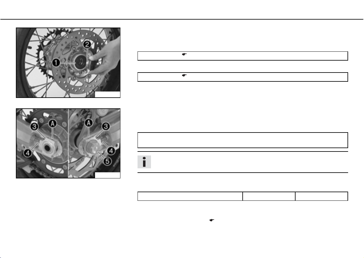
MAINTENANCE WORK ON CHASSIS AND ENGINE 98
ದ Check parts for damage and wear. Replace damaged or worn parts.
ದ Remove the bushingb
seal ringb
Long-life grease ( P. 168)
.
. Clean and grease the roll surfaces of the bushing and the shaft
600628-10
100270-10
ದ Clean and grease the thread of the wheel spindle and nutb
Long-life grease ( P. 168)
ದ Mount the rubber damper and rear sprocket carrier in the rear wheel.
ದ Place the rear wheel in the swingarm and bring the brake disc on the brake caliper into
contact.
ದ Push the rear wheel forward as far as possible and place the chain on the rear sprocket.
ದ Mount the wheel spindle, chain adjuster and nut.
Specification
In order for the rear wheel to be correctly aligned, the markings on the left and right
chain adjusters must be in the same position relative to the reference marksb
.
.
Info
Fit the chain left and right adjustersb in similar positions.
ದ Tighten nutb
Specification
Nut, rear wheel spindle M25x1.5 90bNm (66.4blbfbft)
ದ Operate the foot brake lever repeatedly until the brake linings lie on the brake disc and
there is a tight spot.
ದ Taking rear from work stand. ( P. 57)
.
 Loading...