

Page 1
OWNER'S MANUAL 2008
450 XC ATV
525 XC ATV
ART. NO. 3211251en
Page 2

Page 3
DEAR KTM CUSTOMER 1
'($5.70 &86720(5
Congratulations on your decision to buy a KTM ATV. You are now the owner of a state-of-the-art sports ATV that will give you enormous
pleasure if you service and maintain it accordingly.
We wish you great pleasure riding the vehicle!
Enter the serial numbers of your vehicle below.
Chassis number ( P. 12) Dealer's stamp
Engine number ( P. 12)
Key number ( P. 12)
The owner's manual corresponded to the latest state of this series at the time of printing. Slight deviations resulting from continuing
development and design can however not be completely excluded.
All specifications are not binding. KTM Sportmotorcycle AG in particular reserves the right to modify or delete technical specifications, prices, colors, forms, materials, services, designs, equipment, etc., without prior notice and without specifying reasons, to adapt
these to local conditions, as well as to stop production of a particular model without prior notice. KTM accepts no liability for delivery
options, deviations from illustrations and descriptions, as well as printing and other errors. The models portrayed partly contain special
equipment that does not belong to the regular scope of delivery.
© 2007 by KTM-Sportmotorcycle AG, Mattighofen Austria
All rights reserved
Reproduction, even in part, is permitted only with the express written permission of the copyright owner.
ISO 9001(12 100 6061)
Within the meaning of the international quality management standard ISO 9001, KTM uses quality assurance processes
that lead to the maximum possible quality of the products.
Issued by: TÜV Management Service
KTM-Sportmotorcycle AG
5230 Mattighofen, Austria
Page 4

CONTENTS 2
&217(176
MEANS OF REPRESENTATION ............................................ 4
IMPORTANT NOTES............................................................ 5
Overview of warning labels................................................ 8
VIEW OF VEHICLE............................................................. 10
Vehicle view, front left ................................................... 10
View of vehicle, rear right ............................................... 11
LOCATION OF SERIAL NUMBERS ...................................... 12
Chassis number............................................................. 12
Type label..................................................................... 12
Key number .................................................................. 12
Engine number.............................................................. 12
Setting number, front shock absorber .............................. 12
Setting number, rear shock absorber ............................... 13
OPERATING ELEMENTS.................................................... 14
Clutch lever .................................................................. 14
Reverse gear release lever .............................................. 14
Hand brake lever, parking brake...................................... 14
Throttle lever................................................................. 14
Light switch .................................................................. 15
ENG.bSTOPb
Electric starter button .................................................... 15
Ignition switch .............................................................. 15
Indicator lamp overview ................................................. 15
Emergency OFF switch with rip cord................................ 16
Opening filler cap.......................................................... 16
Closing filler cap ........................................................... 16
Fuel tap........................................................................ 16
Choke........................................................................... 17
Hot start button............................................................. 17
Shift lever..................................................................... 17
Foot brake pedal ........................................................... 17
TIPS ON PUTTING INTO OPERATION ................................. 18
Advice on first use ......................................................... 18
Running in the engine.................................................... 19
RIDING INSTRUCTIONS .................................................... 20
Checks before putting into operation ............................... 20
Starting ........................................................................ 20
Starting up ................................................................... 21
Shifting ........................................................................ 21
shifting to reverse gear ................................................... 22
Disengaging reverse gear ................................................ 22
Braking ........................................................................ 22
Riding .......................................................................... 23
Riding in bends............................................................. 23
Riding downhill ............................................................. 24
Riding uphill................................................................. 24
Riding perpendicular to the slope.................................... 25
Turning on slopes .......................................................... 25
Riding through water ..................................................... 25
Switching off the engine ................................................ 26
Stopping, parking .......................................................... 26
Refueling...................................................................... 27
GREASING AND SERVICE TABLE ....................................... 28
Important maintenance work to be carried out by an
authorized KTM workshop. ............................................. 28
Important maintenance work to be carried out by an
authorized KTM workshop. (as additional order)................ 29
Important checks and maintenance work to be carried
out by the rider. ............................................................ 29
MAINTENANCE ON CHASSIS AND ENGINE ........................ 31
Jacking up the vehicle ................................................... 31
Removing the vehicle from the work stand ....................... 31
Switch ........................................................ 15
Basic information on changing the chassis settings........... 31
Adjusting front shock absorber compression damping ....... 31
Adjusting front shock absorber rebound damping.............. 32
Adjusting front shock absorber cross over......................... 33
Adjusting front shock absorber spring preload .................. 33
Adjusting rear shock absorber compression damping......... 34
Adjusting rear shock absorber rebound damping ............... 35
Adjusting rear shock absorber spring preloadb
Removing the rear shock absorberb
Installing the rear shock absorberb
Toe, checkingb
Adjusting the toeb
Checking/adjusting camberb
Fork offset .................................................................... 41
Adjusting the fork offsetb
Toe width of rear axle..................................................... 41
Adjusting the toe width of rear axleb
Handlebar position ........................................................ 42
Adjusting handlebar positionb
Checking play in gas Bowden cable ................................. 43
Adjusting play in gas Bowden cable................................. 44
Checking the play in the Bowden cable using the reverse
gear release lever........................................................... 44
Adjusting the play in the Bowden cable using the reverse
gear release lever........................................................... 44
Checking chain dirt ....................................................... 45
Cleaning the chain......................................................... 45
Checking the chain tension ............................................ 45
Checking rear sprocket / engine sprocket for wear............. 45
Checking chain wear...................................................... 46
Adjusting chain tension.................................................. 46
Greasing the rear wheel eccentric element ....................... 47
Checking brake discs ..................................................... 47
Checking free play of hand brake lever............................. 48
Adjusting basic position of handbrake lever...................... 48
Checking front brake fluid level....................................... 48
Topping up the front brake fluidb
Checking the front brake linings...................................... 49
Removing front brake liningsb
Mounting front brake liningsb
Changing the front brake liningsb
Checking free play of foot brake lever .............................. 52
Adjusting basic position of footbrake leverb
Checking rear brake fluid level ........................................ 52
Topping up brake fluid of front brakeb
Checking rear brake linings ............................................ 54
Removing rear brake liningsb
Mounting rear brake liningsb
Changing rear brake liningsb
Removing wheel/wheels.................................................. 56
Mounting wheel/wheels .................................................. 56
Tire condition checking.................................................. 57
Checking tire air pressure ............................................... 57
Removing the battery ..................................................... 57
Installing the battery...................................................... 58
Recharging the batteryb
changing main fuse ....................................................... 59
Changing the fuses of individual power-consuming
components .................................................................. 59
Ignition curve plug connection ........................................ 60
Changing ignition curve.................................................. 61
x........................................................... 37
x ...................................................... 38
x ............................................ 41
x .............................................. 58
x .............................. 37
x ............................... 37
x ........................................ 40
x............................. 41
x...................................... 43
x................................. 49
x...................................... 50
x ...................................... 50
x................................. 51
x....................................... 54
x ....................................... 55
x........................................ 55
x ............... 36
x................... 52
x.......................... 53
Page 5

CONTENTS 3
Removing the seat ......................................................... 61
Mounting the seat ......................................................... 61
Removing the radiator spoiler ......................................... 61
Installing the radiator spoiler .......................................... 62
Removing the front cover................................................ 62
Installing the front cover ................................................ 62
Removing the front trim ................................................. 63
Installing the front trim .................................................. 63
Removing the rear fender ............................................... 63
Installing the rear fender ................................................ 64
Removing the engine guard ............................................ 65
Installing the engine guard ............................................. 65
Removing the air filterb
Installing the air filterb
Cleaning air filterb
Adjusting basic position of clutch lever............................ 66
Checking fluid level of hydraulic clutch ........................... 66
Cooling system .............................................................. 67
Radiator fan.................................................................. 67
Checking antifreeze and coolant level .............................. 67
Checking the coolant level.............................................. 68
Draining coolantb
Filling coolant / bleeding cooling systemb
Carburetor - idle ............................................................ 70
Carburetor - adjusting idleb
Emptying the carburetor float chamberb
Checking engine oil level................................................ 72
Changing engine oil and oil filter, cleaning oil
screensb
Draining engine oil, cleaning oil screensb
Removing the oil filterb
Mounting oil filterb
Filling up with engine oilb
Topping up engine oil .................................................... 76
TROUBLESHOOTING......................................................... 77
CLEANING........................................................................ 79
Cleaning the vehicle ...................................................... 79
STORAGE ......................................................................... 80
Storage......................................................................... 80
Putting the vehicle into operation after storage................. 80
TECHNICAL DATA - ENGINE .............................................. 81
Capacity - engine oil ...................................................... 81
Capacity - cooling liquid................................................. 82
TECHNICAL DATA - ENGINE TIGHTENING TORQUES.......... 83
TECHNICAL DATA - CARBURETOR..................................... 85
450/525bXCbATV ........................................................... 85
TECHNICAL DATA - CHASSIS ............................................ 86
Lighting equipment ....................................................... 87
Tires ............................................................................ 87
Capacity - fuel............................................................... 87
TECHNICAL DATA - FRONT SHOCK ABSORBER .................. 88
TECHNICAL DATA - REAR SHOCK ABSORBER .................... 89
TECHNICAL DATA - CHASSIS TIGHTENING TORQUES ........ 90
WIRING DIAGRAM ............................................................ 92
450/525
SUBSTANCES................................................................... 95
AUXILIARY SUBSTANCES.................................................. 97
STANDARDS..................................................................... 98
INDEX .............................................................................. 99
x.................................................................... 73
bXCbATV ........................................................... 92
x............................................... 65
x ............................................... 66
x...................................................... 66
x ....................................................... 68
x ..................... 69
x ......................................... 71
x ....................... 72
x ..................... 73
x............................................... 74
x ..................................................... 75
x ........................................... 75
Page 6
MEANS OF REPRESENTATION 4
0($162)5(35(6(17$7,21
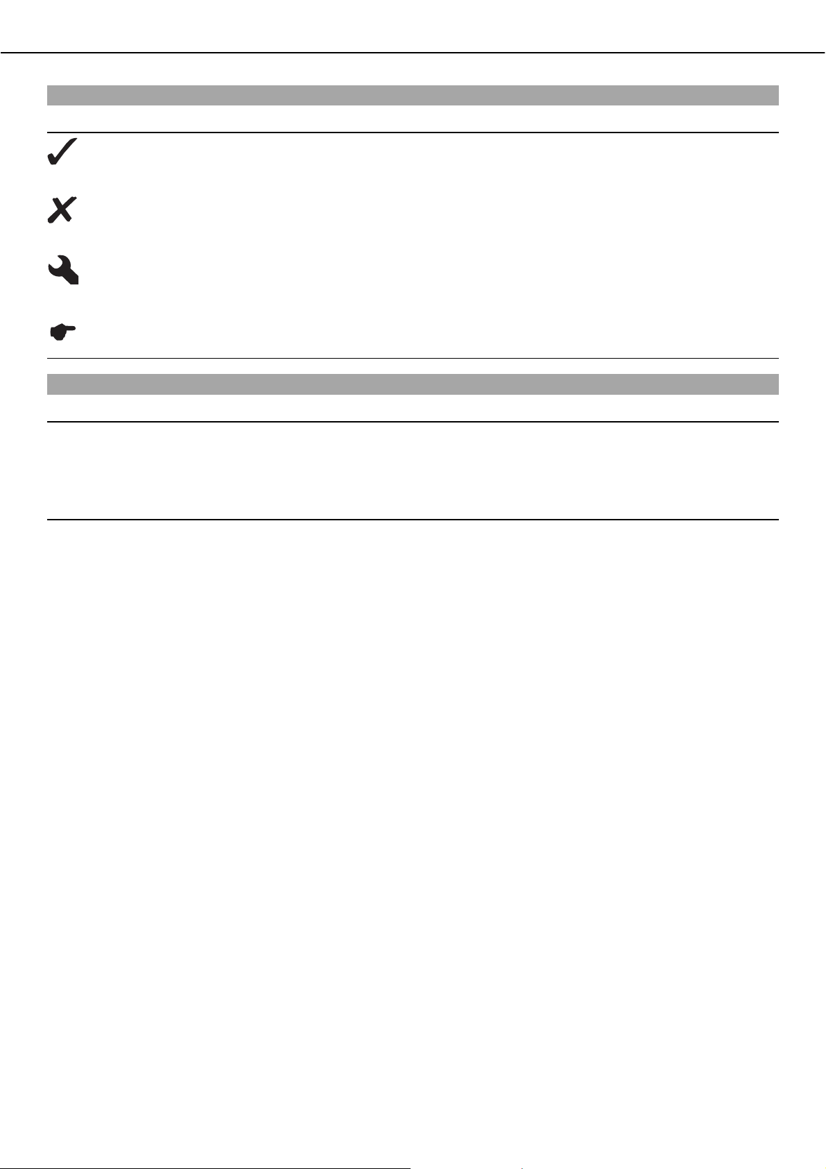
Symbols used
The symbols used are explained in the following.
Indicates an expected reaction (e.g. of a work step or a function).
Indicates an unexpected reaction (e.g. of a work step or a function).
All work marked with this symbol requires specialist knowledge and technical understanding. In the interest of
your own safety, have these jobs done in an authorized KTM workshop! There, your vehicle will be serviced optimally by specially trained experts using the specialist tools required.
Identifies a page reference (more information is provided on the specified page).
Formats used
The typographical and other formats used are explained in the following.
Specific name Identifies a specific name.
®
Name
Brand™ Identifies a brand in merchandise traffic.
Identifies a protected name.
Page 7
IMPORTANT NOTES 5
,03257$17127(6
Use definition
KTM ATVs are designed and built to withstand the normal stresses and strains of competitive use. The vehicles comply with currently
valid regulations and categories of the top international motorsport organizations.
Warning
Danger of accidentsಘIncorrect assessment of riding situations.
ದ The vehicle may only be ridden by persons over the age of 16.
Info
The ATV must be used only on secluded property remote from public road traffic.
The ATV is designed for off-road sport endurance competition (Enduro) and not for the predominant motocross use.
Maintenance
A prerequisite for perfect operation and prevention of wear is that the engine and chassis maintenance and adjustment work described
in the owner's manual are properly carried out. Poor adjustment and tuning of the engine and chassis can lead to damage and breakage of components.
Using the vehicle in extreme conditions such as very muddy or wet terrain can lead to above-average wear of components such as the
transmission train or the brakes. For this reason, it may be necessary to service or replace worn parts before the limit specified in the
greasing and service table is reached.
Pay careful attention to the prescribed running-in period, inspection and maintenance intervals. If you observe these exactly, you will
ensure a much longer service life for your vehicle.
Warranty
The maintenance work prescribed in the greasing and service table must be carried out in an authorized KTM workshop and confirmed
in the customer's service record, since otherwise no warranty claims will be recognized. No warranty claims can be considered for
damage resulting from manipulations and alterations to the vehicle.
Fuel, oils, etc.
You should use the fuels, oils and greases according to specifications as listed in the owner's manual.
Spare parts, accessories
For your own safety, use only spare parts and accessories approved by KTM. KTM accepts no liability for other products and any
resulting damage or loss.
Transport
Note
Danger of damageಘDanger of damage from accidental rolling of vehicle.
ದ Park the vehicle on a surface that is as horizontal as possible and activate the parking brake.
Note
Fire hazardಘSome components (engine, radiator and exhaust system) get very hot when the engine is running.
ದ Do not place the vehicle where there are flammable or explosive substances.
ದ Switch off the engine.
ದ Turn the handleb
ದ Use straps or other suitable devices to secure the vehicle against accidents or falling over.
ದ Pull the hand brake lever, push the locking pawlb
of the fuel tap to the OFF position. (Figureb100013-10b P. 16)
down and release the hand brake lever. (Figureb100006-10b P. 14)
Environment
Offroad riding is a wonderful sport and we naturally hope that you will be able to enjoy it to the fullest. However, it is a potential problem for the environment and can lead to conflicts with other persons. But if you use your vehicle responsibly, you can ensure that such
problems and conflicts do not have to occur. To protect the future of offroad sport, make sure that you use your ATV legally, display
environmental consciousness, and respect the rights of others.
Page 8

IMPORTANT NOTES 6
Rider training
If you have never ridden an ATV before, it is important that you participate in a driver training course before you ride the vehicle for
the first time.
A professional trainer will show you how to handle your ATV safely in various riding situations and on different terrain.
Your KTM dealer will be glad to advise you.
Page 9

IMPORTANT NOTES 7
Page 10
IMPORTANT NOTES 8
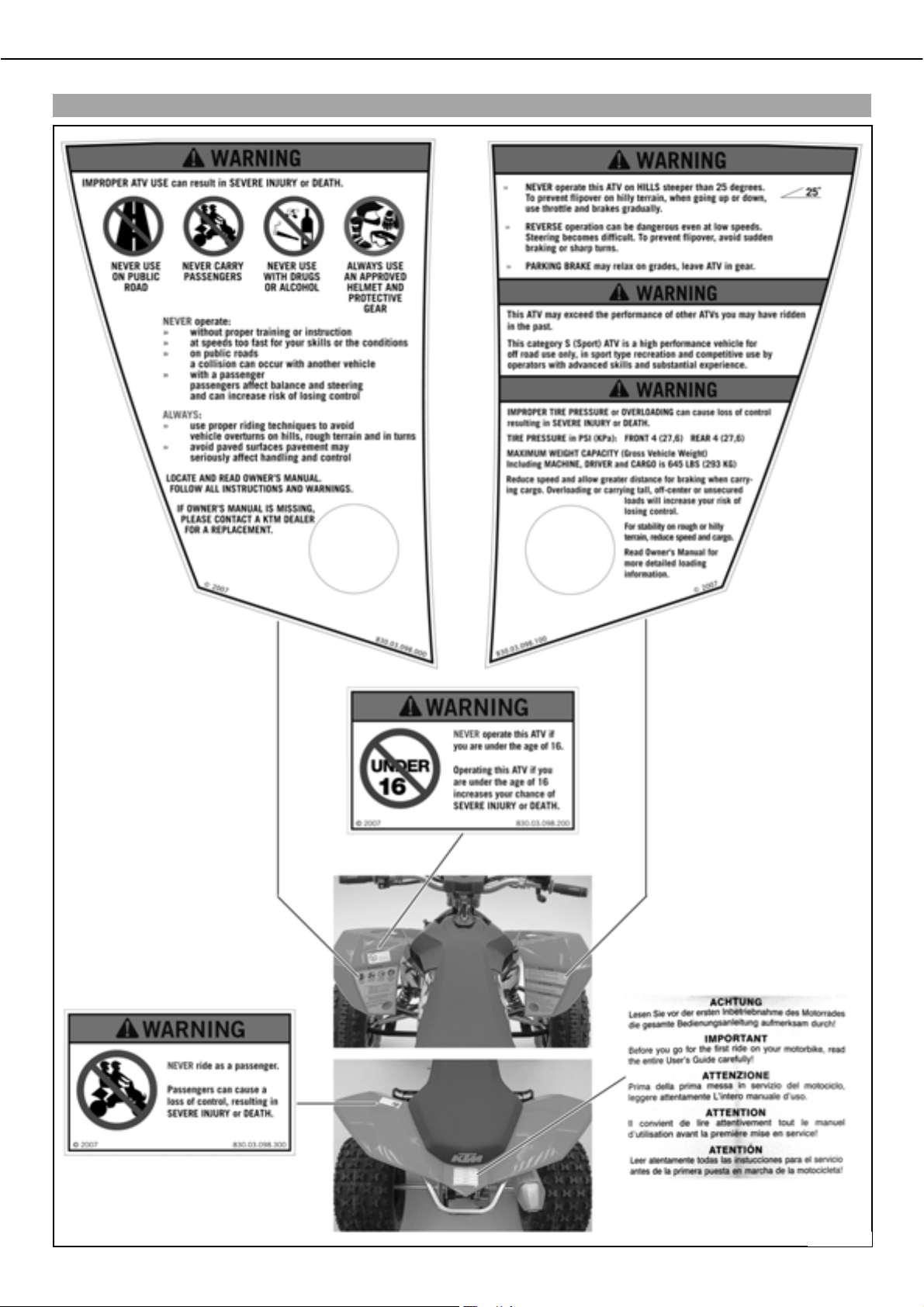
Overview of warning labels
100106-10
Page 11
IMPORTANT NOTES 9
Notes/warning notes
Pay attention to the specified notes and warnings.
Info
Various notes and warning labels are attached to the vehicle. Do not remove any notes or warning labels. If they are missing,
you or others may not recognize dangers and may therefore be injured.
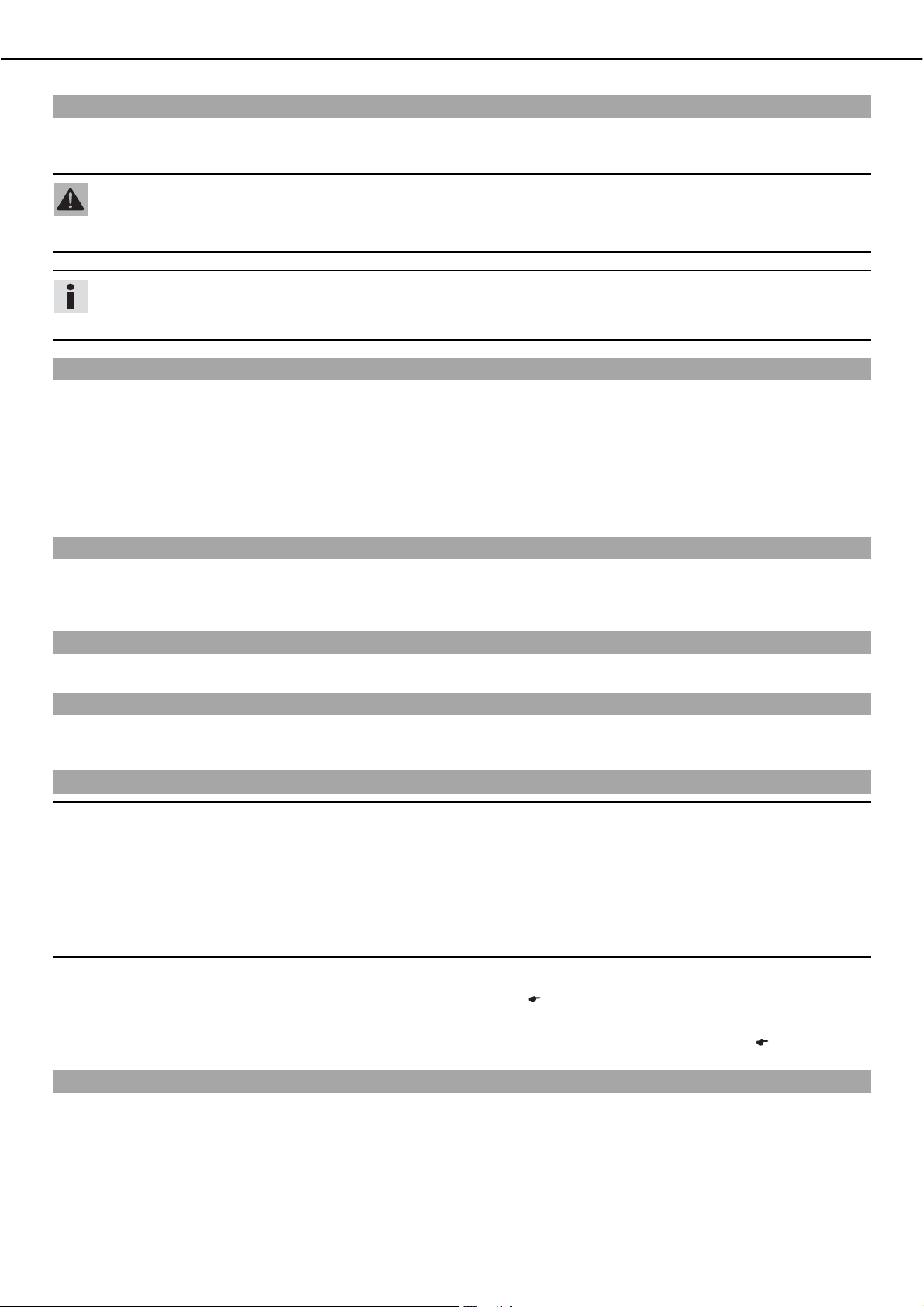
Grades of risks
Danger
Danger that leads immediately and certainly to severe and permanent injury or death.
Warning
Danger that will probably lead to severe and permanent injury or death.
Note
Danger of serious damage to machine or material.
Warning
Risk of environmental damage.
OWNER'S MANUAL
ದ Read this owner's manual carefully and completely before making your first trip. It contains a lot of information and tips to help
you operate and handle your vehicle. Only then will you find out how to customize the vehicle ideally for your own use and how you
can protect yourself from injury. The owner's manual also contains important information on servicing the vehicle.
ದ The owner's manual is an important component of the vehicle and should be handed over to the new owner if the vehicle is sold.
Page 12
VIEW OF VEHICLE 10
9,(:2)9(+,&/(
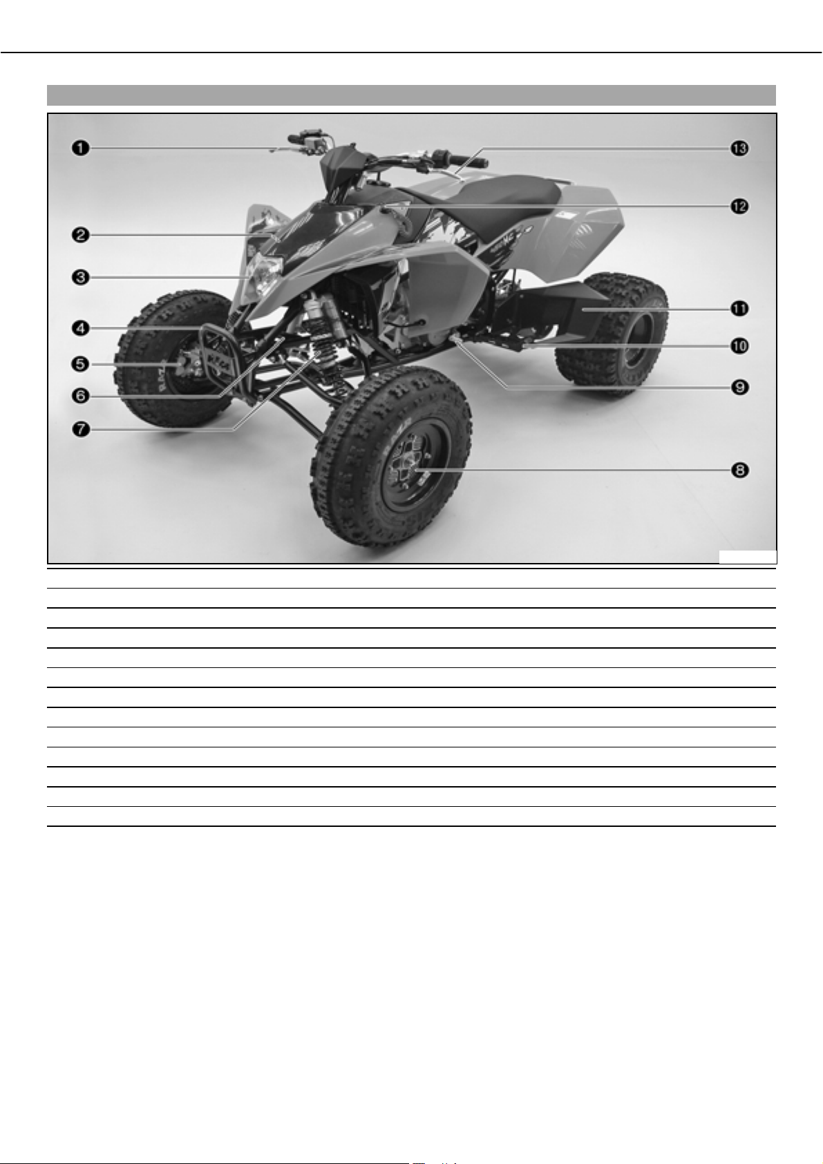
Vehicle view, front left
1 Hand brake lever
2 Fuse box
3 Headlight
4 Front shock absorber
5 Right-hand brake caliper
6 Steering damper holder (steering damper is optional)
7 Front left shock absorber
8 Outside brake disk guard
9 Shift lever
10 Left footrest
11 Heel protector
12 Emergency OFF switch with rip cord
13 Clutch lever
600148-10
Page 13
VIEW OF VEHICLE 11
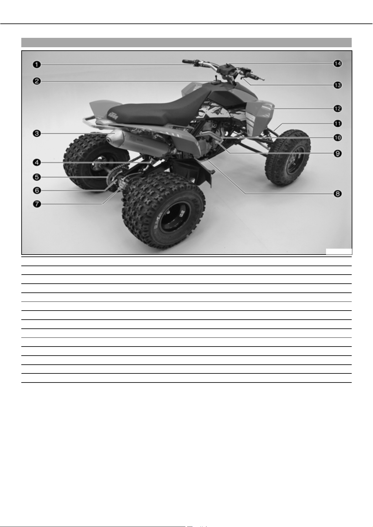
View of vehicle, rear right
1 Light switch, electric starter button, ENG.bSTOPbswitch
2 Filler cap
3 Main silencer
4 Rear shock absorber
5 Rear sprocket with chain
6 Rear wheel eccentric element
7 Rear brake
8 Foot brake pedal
9 Compensating tank for coolant
10 Manifold
11 Top A-arm
12 Front right fender
13 Throttle lever
14 Ignition switch
600149-10
Page 14
LOCATION OF SERIAL NUMBERS 12
/2&$7,212)6(5,$/ 180%(56
Chassis number
The chassis numberb is stamped on the right side of the frame in the vicinity of the
upper control arm.
100002-10
Type label
The type labelb is located on the frame tube on the right in front of the radiator.
Key number
Engine number
100034-10
The key numberb is indicated on thebKEYCODECARD.
Info
You need the key number to order a replacement key. Keep thebKEYCODECARD in
a safe place.
100089-10
The engine numberb is stamped on the left side of the engine under the engine
sprocket.
100001-10
Setting number, front shock absorber
100033-10
The setting numberb is stamped into the top of the shock absorber.
Page 15
LOCATION OF SERIAL NUMBERS 13
Setting number, rear shock absorber
The setting numberb is stamped into the top of the shock absorber.
100032-10
Page 16
OPERATING ELEMENTS 14
23(5$7,1*(/(0(176
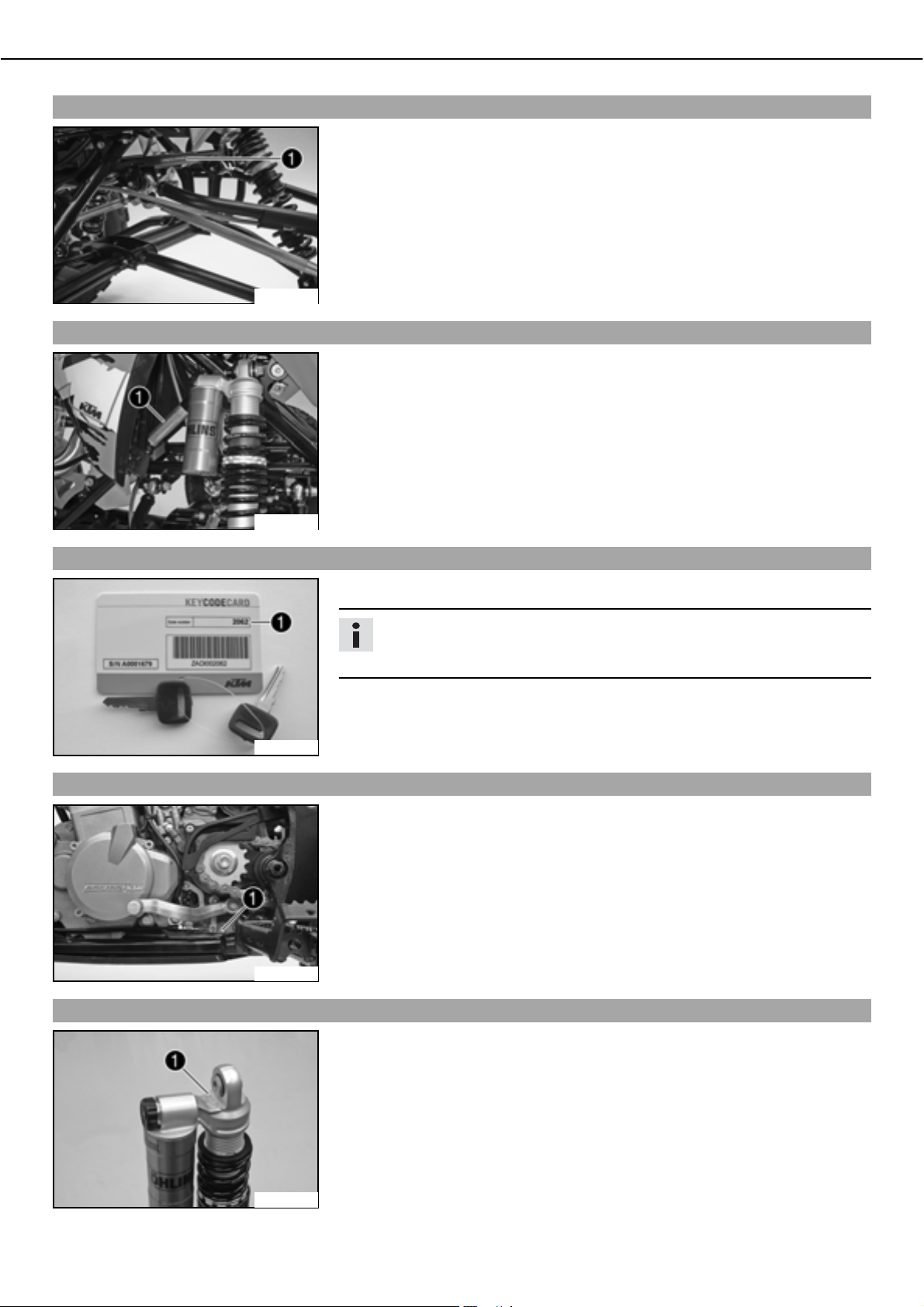
Clutch lever
The clutch leverb is fitted on the left side of the handlebar.
Possible states
• Clutch lever in neutral position ದbIn this position, the engine is force-locked with
the gear and the starting circuit is interrupted. The electric starter does not turn
over when the electric starter button is pressed.
• Clutch lever pulled ದbIn this position, the force lock between the engine and the
gear is broken and the starting circuit is closed. The electric starter turns over
when the electric starter button is pressed.
100004-10
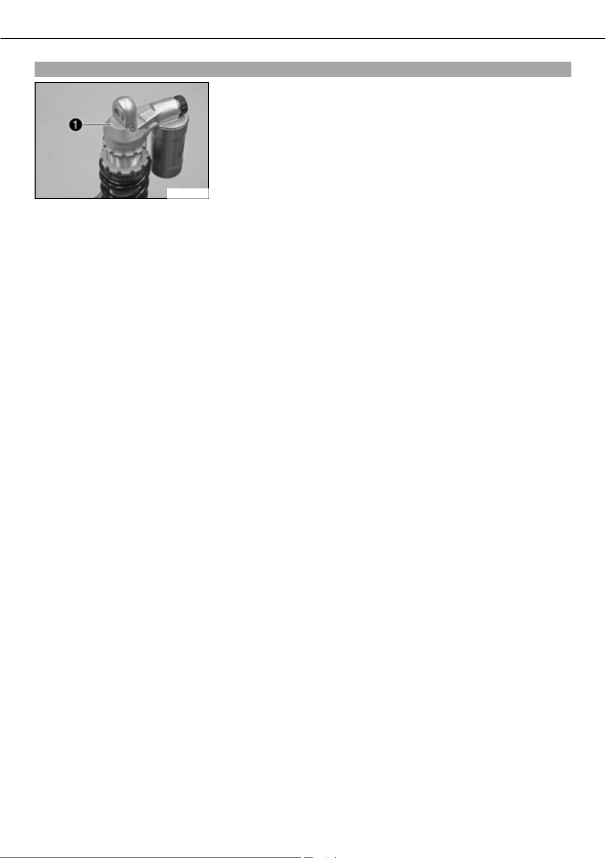
Reverse gear release lever
The clutch is hydraulically operated and self-adjusting.
The reverse gear release leverb is fitted on the left side of the handlebar.
Reverse gear can only be engaged when the reverse gear release lever is activated while
the vehicle is at a standstill.
100005-10
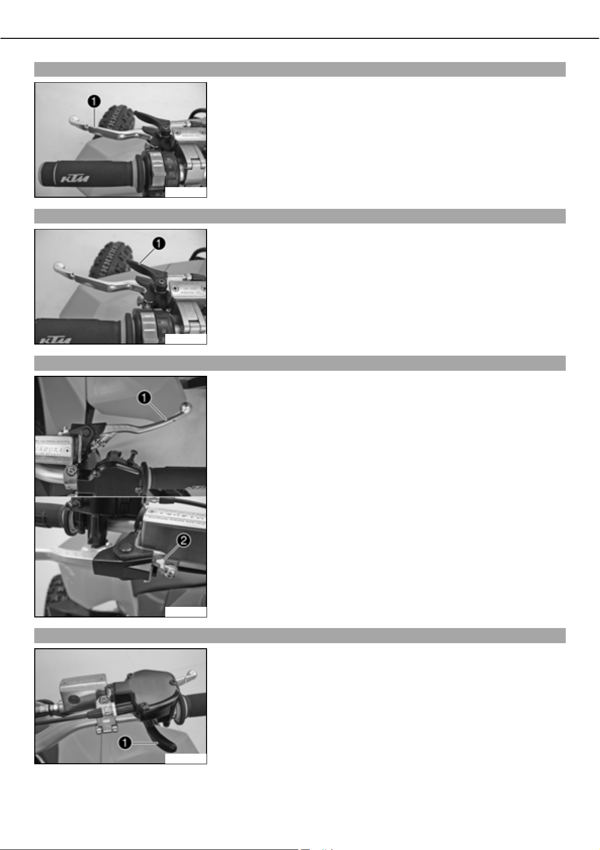
Hand brake lever, parking brake
100006-10
The hand brake leverb is located on the right side of the handlebar and operates the
front brakes.
The hand brake lever is combined with the parking brake, which blocks the front
wheels to prevent the vehicle from rolling away.
To activate the parking brake, pull the hand brake lever, push the locking pawlb
down
and release the hand brake lever.
Possible states
• Hand brake lever in basic position ದbFront wheels are not blocked.
• Hand brake lever pulled and locked in position ದbFront wheels are blocked.
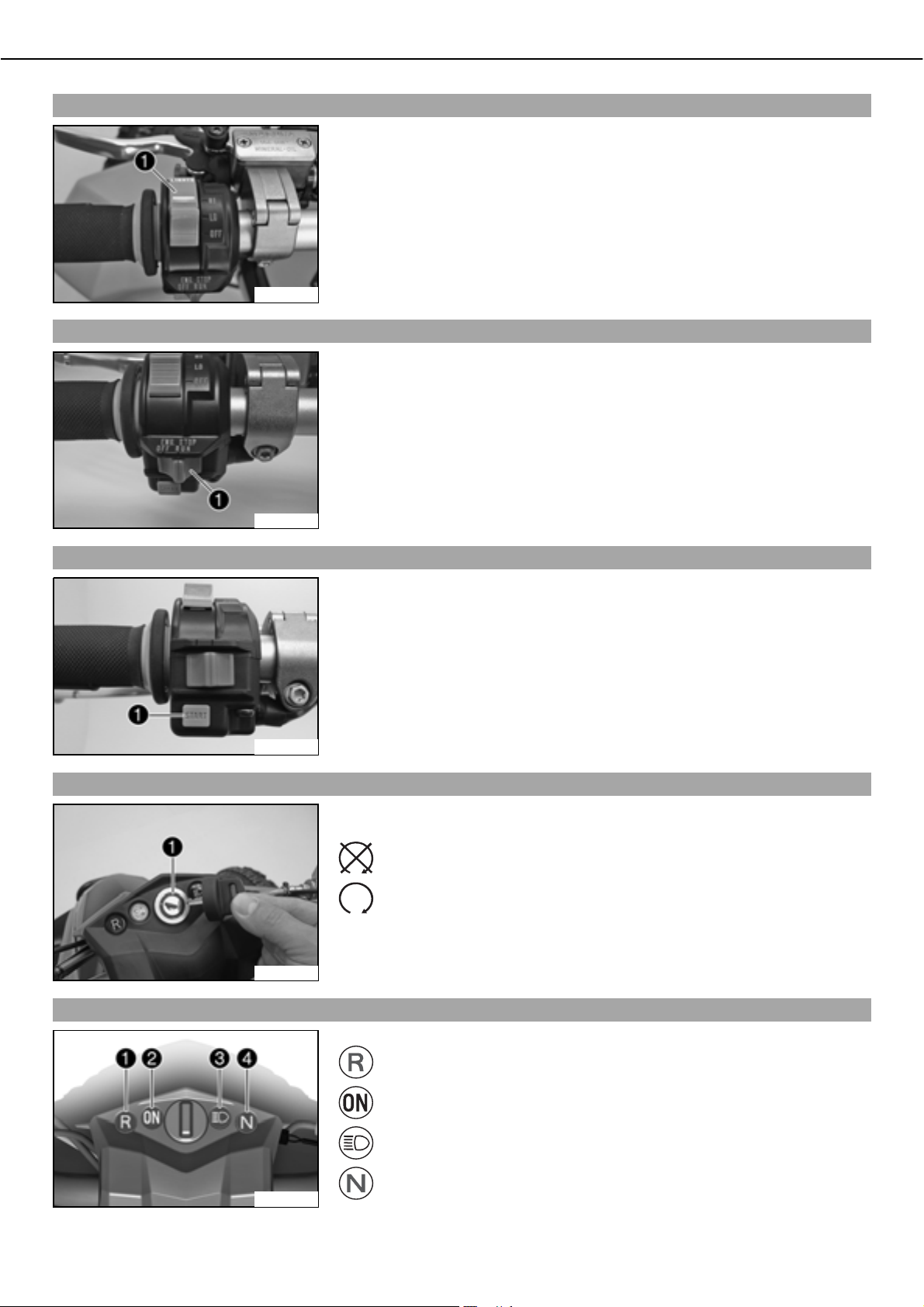
Throttle lever
The throttle leverb is fitted on the right side of the handlebar.
The throttle lever is used to control the engine speed.
100007-10
Page 17
OPERATING ELEMENTS 15
Light switch
The light switchb is fitted on the left side of the handlebar.
Possible states
• High beam on HI ದbLight switch is turned upwards. In this position, the high beam
and the tail light are switched on.
• Low beam on LO ದbLight switch is at the middle setting. In this position, the low
beam and tail lights are switched on.
• Lights off OFF ದbLight switch has been swiveled down. In this position, all lights
are switched off.
100011-10
ENG.bSTOPbSwitch
ThebENG.bSTOPbswitchb is fitted on the left side of the handlebar.
Possible states
• Ignition offbOFF ದbIn this position, the ignition circuit is interrupted, a running
engine stops, and the engine cannot be started.
• Ignition onbRUN ದbIn this position, the ignition circuit is closed and the engine can
be started.
Electric starter button
Ignition switch
100030-10
The STARTb electric starter button is fitted on the left side of the handlebar.
Possible states
• Electric starter button in basic position
• Electric starter button pressed ದbIn this position, the electric starter is actuated.
100029-10
The ignition switchb is located on the instrument support.
Possible states
Ignition off ದbIn this position, the ignition circuit is interrupted, a running
engine stops, and a non-running engine will not start.
Ignition on ದbIn this position, the ignition circuit is closed and the engine
can be started.
Indicator lamp overview
100031-10
400288-10
Possible states
Reverse gear indicator lampb
Ignition indicator lampb
lights up yellow ದbIgnition is switched on.
High beam indicator lampb
Idle speed indicator lampb
lights up green ದbTransmission is switched
to idle.
lights up red ದbReverse gear is engaged.
lights up blue ದbHigh beam is switched on.
Page 18
OPERATING ELEMENTS 16
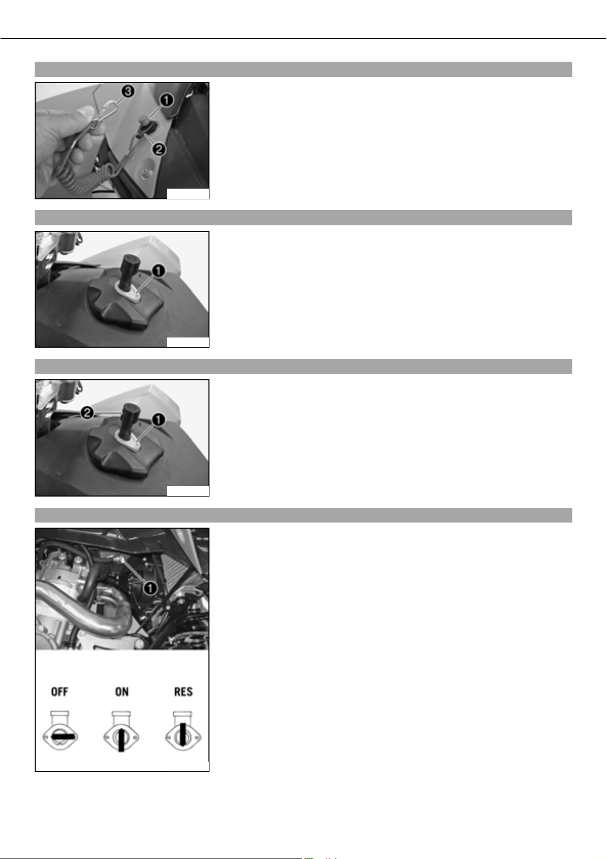
Emergency OFF switch with rip cord
The emergency OFF switchb is mounted on the left in front of the fuel tank. A rip
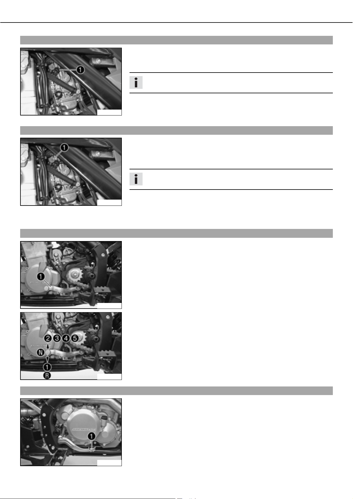
Opening filler cap
100010-10
cord is attached to the clipb
of a carabiner
.
The emergency OFF switch shuts the engine off if the rider falls off the vehicle.
Possible states
• Clip is pulled off ದbThe ignition circuit is interrupted, a running engine stops and a
non-running engine will not start.
• Clip is mounted ದbThe ignition circuit is closed and the engine can be started.
ದ Press release buttonb, turn filler cap counterclockwise and lift it free.
. It can be attached to the clothing of the rider by means
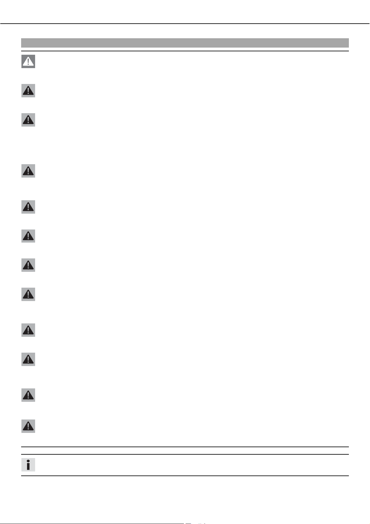
Closing filler cap
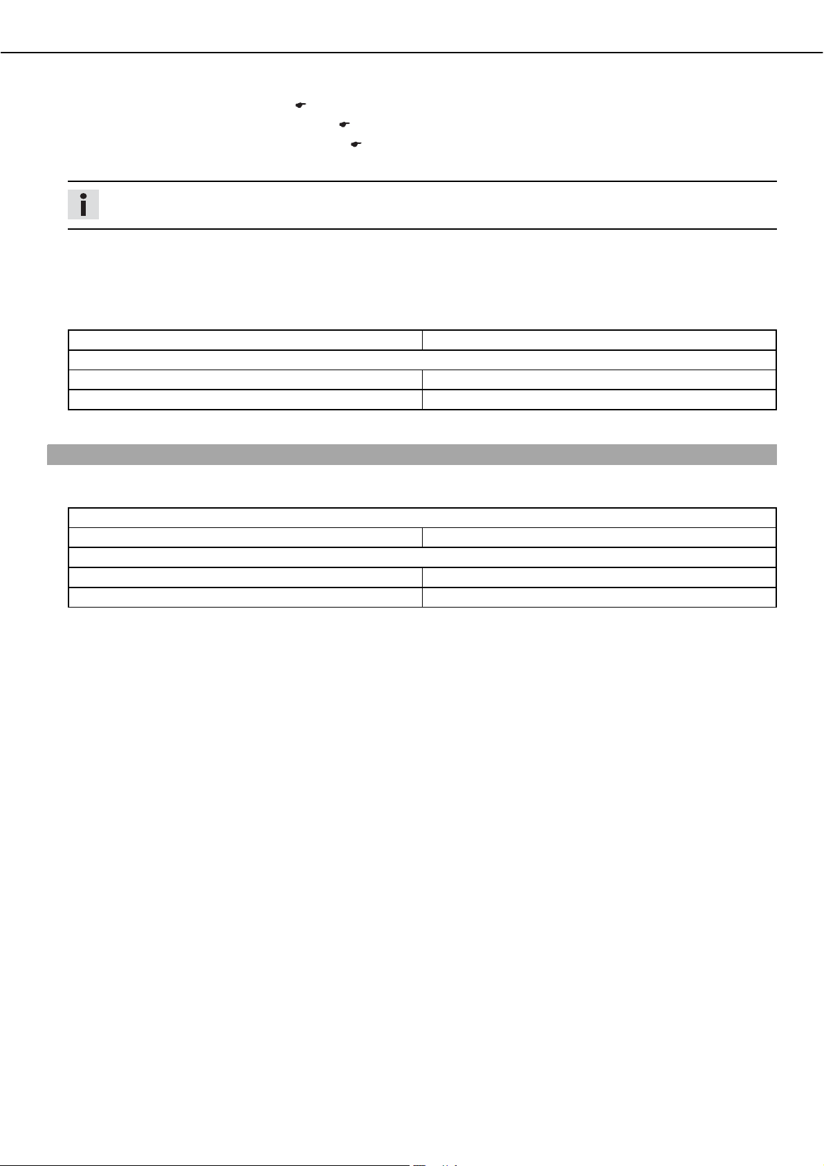
Fuel tap
100012-10
100012-11
ದ Replace the filler cap and turn clockwise until the release buttonb locks in place.
ದ Check the fuel tank breatherb
to ensure it is properly seated.
» If the fuel tank breather is at an angle or loose:
ದ Correctly mount the fuel tank breather.
The fuel tap is located on the right side of the fuel tank.
With the tap handleb
on the fuel tap, you can open or close the supply of fuel to the
carburetor.
Possible states
• Fuel supply closed OFF ದbNo fuel can flow from the tank to the carburetor.
• Fuel supply open ON ದbFuel can flow from the tank to the carburetor. The fuel tank
empties down to the reserve.
• Reserve fuel supply open RES ದbFuel can flow from the tank to the carburetor. The
fuel tank empties completely.
100013-10
Page 19
OPERATING ELEMENTS 17
Choke
The choke knobb is fitted on the left side of the carburetor.
Activating the choke function frees an opening through which the engine can draw
extra fuel. This gives a richer fuel-air mixture, which is needed for a cold start.
Info
If the engine is warm, the choke function must be deactivated.
Possible states
100014-10
Hot start button
• Choke function activated ದbThe choke lever is pulled out to the stop.
• Choke function deactivated ದbThe choke lever is pushed in to the stop.
The hot start button (red)b is fitted on the left side of the carburetor.
Activating the hot start function frees an opening in the carburetor through which the
engine can draw extra air. This gives a leaner fuel-air mixture, which is needed for a
hot start.
Info
If the engine is cold, the hot start function must be deactivated.
Shift lever
100015-10
100018-10
Possible states
• Hot start function activated ದbThe hot start button is pulled out to the stop.
• Hot start function deactivated ದbThe hot start button is pushed in as far as possible.
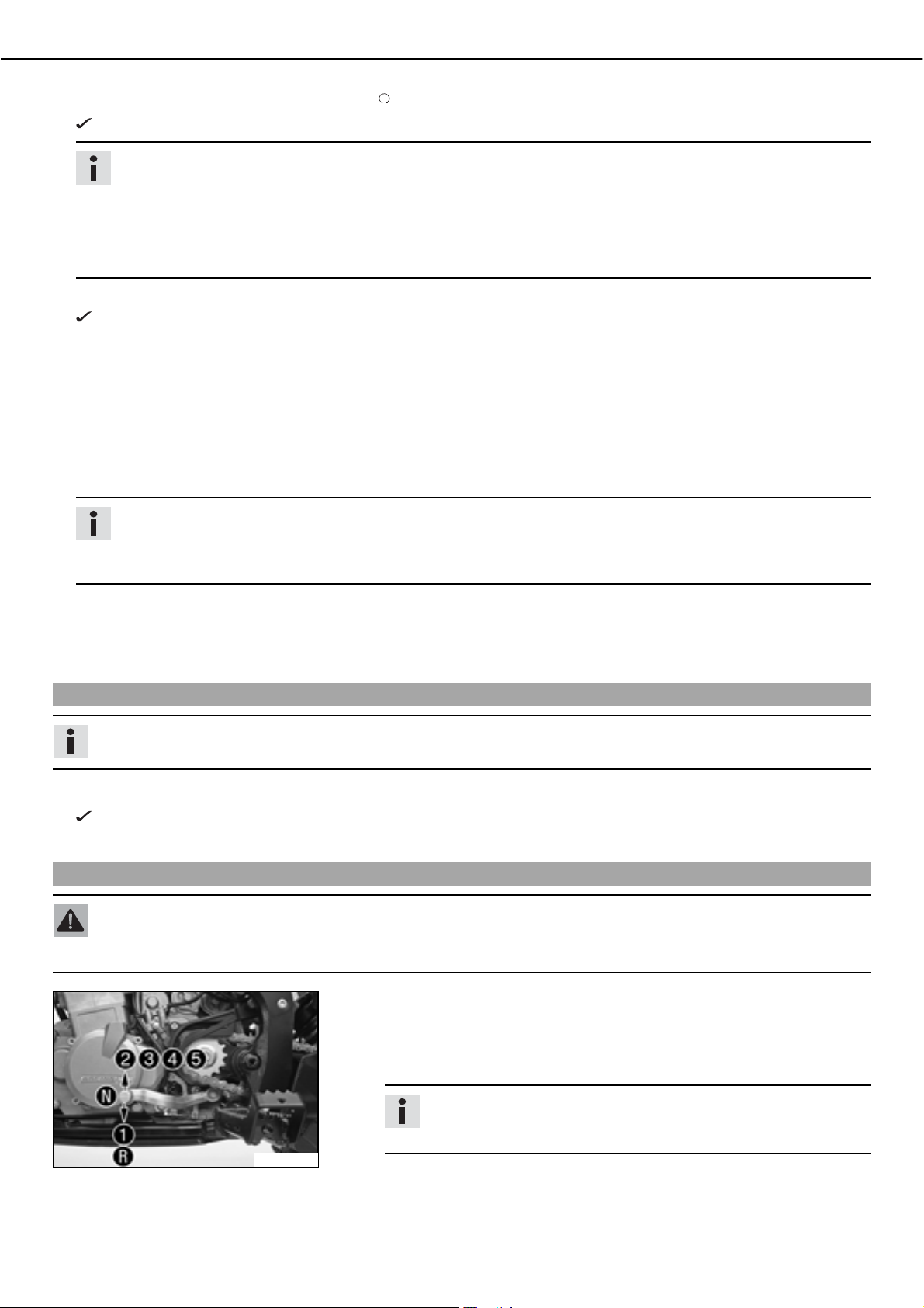
The shift leverb is mounted on the left side of the engine.
The gear positions can be seen in the photograph.
The neutral or idle position is between the first and second gears.
Reverse gear can only be engaged with the vehicle at a standstill and the lever pulled.
Foot brake pedal
100017-10
The foot brake pedalb is located in front of the right footrest and operates the rear
wheel brake.
100016-10
Page 20
TIPS ON PUTTING INTO OPERATION 18
7,36213877,1* ,17223(5$7,21
Advice on first use
Danger
Danger of accidentsಘDanger from inadequate traffic experience.
ದ Do not use the vehicle if you are inexperienced or if you have consumed alcohol or drugs.
Warning
Danger of accidentsಘIncorrect assessment of riding situations.
ದ The vehicle may only be ridden by persons over the age of 16.
Warning
Danger of accidentsಘUnaccustomed handling of the ATV.
ದ If you have never ridden an ATV before, it is important that you participate in a driver training course before you ride the
vehicle for the first time.
ದ A professional trainer will show you how to handle your ATV safely in various riding situations and on different terrain. Your
KTM dealer will be glad to advise you.
Warning
Risk of injuryಘRisk of injury by missing/inadequate protective clothing.
ದ Wear protective clothing (helmet, boots, gloves, pants and jacket with protectors) every time you ride the motorcycle.
Always wear protective clothing, which must be in perfect condition and meet legal requirements.
Warning
Danger of crashingಘImpairment of riding behavior due to different tire tread patterns on front and rear wheels.
ದ The front and rear wheels must be fitted with tires with similar tread patterns to prevent loss of control over the vehicle.
Warning
Danger of accidentsಘCritical riding behavior due to inappropriate riding.
ದ Adapt your riding speed to the road conditoins and your riding ability.
Warning
Danger of accidentsಘAccident risk caused by presence of a passenger.
ದ Your vehicle is not designed to carry passengers. Do not ride with a passenger.
Warning
Danger of accidentsಘBrake system failure.
ದ If the foot brake pedal is not released, the brake linings drag permanently. The rear brake can fail due to overheating. Take
your foot off the foot brake pedal if you do not want to brake.
Warning
Danger of accidentsಘUnstable riding behavior.
ದ Do not exceed the maximum permitted weight and axle loads.
Warning
Risk of misappropriationಘUsage by unauthorized persons.
ದ Never leave the vehicle unattended while the engine is running. Secure the vehicle against use by unauthorized persons.
Always remove the ignition key.
Warning
Danger of accidentsಘInstable handling from loaded luggage.
ದ The vehicle is not designed to carry luggage. Do not attach luggage to the vehicle.
Warning
Danger of accidentsಘPoor recognizability of vehicle on hilly terrain and/or sand dunes.
ದ Attach a safety flag to the vehicle.
Info
When using your vehicle, remember that others may feel disturbed by excessive noise.
ದ Make sure that the pre-delivery inspection work has been carried out by an authorized KTM workshop.
You receive a delivery certificate and the service record at vehicle handover.
ದ Before your first trip, read the entire operating instructions carefully.
Page 21
TIPS ON PUTTING INTO OPERATION 19
ದ Get to know the operating elements.
ದ Adjust the basic position of clutch lever. ( P. 66)
ದ Adjust the basic position of the handbrake lever. ( P. 48)
ದ
Adjust the basic position of the footbrake lever.b
ದ Become accustomed to handling the vehicle on a suitable piece of land before making a longer trip.
Info
Offroad, you should be accompanied by another person on another machine so that you can help each other.
ದ Do not make any offroad trips that over-stress your ability and experience.
ದ Hold the handlebar firmly with both hands and keep your feet on the footrests when riding.
ದ Do not make any changes to the vehicle and use only KTM approved parts.
ದ Do not exceed the overall maximum permitted weight and the axle loads.
Specification
Maximum permissible overall weight 293bkg (646blb.)
Maximum allowable axle load
Front 144bkg (317blb.)
Rear 149bkg (328blb.)
ದ Run the engine in.
x ( P. 52)
Running in the engine
ದ During the running-in phase, do not exceed the specified engine speed and engine performance.
Specification
Maximum engine speed
During the first 3 service hours 7,000brpm
Maximum engine performance during the running-in period
During the first 3 service hours ืb50b%
During the next 12 service hours ืb75b%
ದ Avoid fully opening the throttle!
Page 22
RIDING INSTRUCTIONS 20
5,',1*,16758&7,216
Checks before putting into operation
Info
Make sure that the vehicle is in a perfect technical condition before use.
Info
In the interests of riding safety, make a habit of making a general check before you ride.
ದ Check the engine oil level. ( P. 72)
ದ Check the engine for oil loss.
ದ Check the fuel supply.
ದ Check the chain tension. ( P. 45)
ದ Check the chain dirt accumulation. ( P. 45)
ದ Check the tire condition. ( P. 57)
ದ Checking the tire air pressure. ( P. 57)
ದ Check the front brake fluid level. ( P. 48)
ದ Check the rear brake fluid level. ( P. 52)
ದ Check the front brake linings. ( P. 49)
ದ Check the rear brake linings. ( P. 54)
ದ Check brake system function.
ದ Check that the rear hubs are tight.
ದ Check that the footrests are tight.
ದ Check the handlebar bridge bearing for excessive play.
ದ Check the handlebar for smooth operation and play.
ದ Check the coolant level. ( P. 68)
ದ Check the cooling system for leakage.
ದ Check that all operating elements are correctly adjusted and free to move.
ದ Check that the electrical equipment is functioning properly.
Starting
Danger
Danger of poisoningಘExhaust gases are poisonous and can result in unconsciousness and/or death.
ದ When running the engine, always make sure there is sufficient ventilation, and do not start or run the engine in a closed
space.
Note
Engine failureಘHigh engine speeds in cold engines have a negative effect on the service life of the engine.
ದ Always warm up the engine at low engine speeds.
Info
If the engine is unwilling to start, the cause can be old fuel in the float chamber. The flammable elements of the fuel evaporate after a long time of standing.
If the float chamber is filled with fresh fuel, the engine starts immediately.
Press the starter for a maximum of 5 seconds. Wait for a least 5 seconds until trying again.
Conditions
Vehicle has not been operated: ุb1bweek
ದ
Empty the carburetor float chamber.b
ದ Turn the handleb
Fuel can flow from the tank to the carburetor.
ದ Mount the vehicle.
ದ Insert the clipb
ದ Press thebENG.bSTOPbswitch into thebRUN position.
of the fuel tap to the ON position. (Figureb100013-10b P. 16)
into the emergency OFF switch and fasten the rip cord to the clothing of the rider. (Figureb100010-10b P. 16)
x ( P. 72)
Page 23
RIDING INSTRUCTIONS 21
ದ Turn the key in the ignition switch to thebpositionb .
The yellow ignition indicator lampbON lights up.
Info
Under no circumstances should you open the throttle when switching on the ignition!
The vehicle is equipped with a safety system that switches off the engine in case of a malfunction in the throttle lever,
Bowden cable or carburetor. When the ignition is switched on, a system check is performed during which the throttle lever
must be in its basic position. If not, the safety system detects a malfunction and blocks the ignition current. When the
electric starter button is activated, the electric starter turns over the engine, but the engine does not start because there
is no ignition spark.
ದ Shift gear to neutral.
The green idling speed indicator lampbN light up.
Conditions
Engine cold
ದ Pull choke lever out as far as possible.
Conditions
Engine is hot
ದ Pull the hot start button (red) all the way out.
ದ Pull the clutch lever.
ದ Press the electric starter button.
Info
When the clutch lever is not pulled, the starting circuit is not closed. The electric starter does not turn over when the electric starter button is pressed.
Don't open the throttle.
ದ Release the clutch lever.
Conditions
Engine hot and running
ದ Push the hot start button in as far as possible when the engine is running.
Starting up
Info
Switch your lights on before leaving. You will then be seen earlier by other motorists.
ದ Pull the hand brake lever and release it again.
Locking pawl moves into its basic position, parking brake is deactivated.
ದ Pull the clutch lever, engage 1st gear, release the clutch lever slowly and simultaneously open the throttle carefully.
Shifting
Warning
Danger of accidentsಘIf you change down at high engine speed, the rear wheels can block.
ದ Do not change into a low gear at high engine speed. The engine races and the rear wheels can block.
100017-10
Conditions
When conditions allow (incline, road situation, etc.), you can shift into a higher
gear.
ದ Release the throttle while simultaneously pulling the clutch lever, shift into the
next gear, release the clutch and open the throttle.
Info
The position of the 5 forward gears can be seen in the illustration. First
gear is used for starting off or for steep inclines.
ದ To shift down, brake if necessary and close the throttle at the same time.
ದ Pull the clutch lever and shift into a lower gear, release the clutch lever slowly and
open the throttle or shift again.
Page 24
RIDING INSTRUCTIONS 22
shifting to reverse gear
Warning
Danger of accidentsಘDanger of accidents from blocked rear wheels if reverse gear is engaged while the vehicle is rolling.
ದ To engage reverse gear, it is important to stop the vehicle first and have the engine at idle speed.
Note
Transmission damageಘDanger of transmission damage when engaging reverse gear while the vehicle is rolling.
ದ To engage reverse gear, it is important to stop the vehicle first and have the engine at idle speed.
ದ Stop the vehicle and run the engine at idling speed.
ದ Activate the clutch and engage 1st gear.
ದ Apply light pressure to the shift lever and activate the reverse gear release lever. Press the shift lever all the way down with your
foot to engage reverse gear.
ದ Release the reverse gear release lever.
ದ Look toward the rear and slowly release the clutch lever while depressing the accelerator carefully.
Info
The engine speed is limited when reverse gear is engaged.
Disengaging reverse gear
Warning
Danger of rolloversಘThe vehicle can roll over if the clutch lever is released with the forward gear engaged while the vehicle is
rolling backward.
ದ To disengage reverse gear, it is important that you stop the vehicle first.
Warning
Danger of accidentsಘDanger of accidents from blocked rear wheels if reverse gear is disengaged while the vehicle is rolling.
ದ To disengage reverse gear, it is important that you stop the vehicle first.
Note
Transmission damageಘDanger of transmission damage when disengaging reverse gear while the vehicle is rolling.
ದ To disengage reverse gear, it is important that you stop the vehicle first.
ದ Activate the clutch, stop the vehicle and let the engine run at idling speed.
ದ Press the shift lever up until 1st gear engages.
Info
The reverse gear release lever no longer needs to be activated.
ದ Slowly release the clutch lever while carefully depressing the accelerator or shifting into neutral.
Braking
Warning
Danger of accidentsಘIf you brake too hard, the wheels can lock. When the front wheels lock, the vehicle can no longer be
steered.
ದ Adapt your braking to the traffic situation and the road conditions.
Warning
Danger of accidentsಘReduced braking caused by spongy pressure point of front or rear brake.
ದ Have the brake system checked in an authorized KTM workshop, and do not ride any further.
Warning
Danger of accidentsಘReduced braking due to wet or dirty brakes.
ದ Clean or dry dirty or wet brakes by riding and braking gently.
ದ Use the hand brake lever to activate the front brakes and the foot brake pedal to activate the rear brakes.
ದ When braking, release the throttle and apply the front and rear brakes at the same time.
Page 25
RIDING INSTRUCTIONS 23
ದ Shift the transmission to lower gears according to the vehicle's speed.
ದ Braking should always be completed before you go into a bend.
ದ On long downhill stretches, use the braking effect of the engine. Change down one or two gears, but do not overstress the engine.
In this way, you have to brake far less and the brakes do not overheat.
Riding
Info
If you hear unusual noises while riding, stop immediately, switch off the engine and contact an authorized KTM workshop.
If the vehicle goes out of control and you fall off the vehicle, the clip of the emergency OFF switch is pulled off by the rip cord
attached to your clothing. This short-circuits the ignition circuit and the engine switches off.
ದ During normal operation, you sit erect on the vehicle with both hands on the handlebar and both feet on the footrests.
ದ If the choke function was activated, deactivate it after the engine has warmed up.
ದ After reaching maximum speed by fully opening the throttle, close the throttle so it is 3/4 open.
This barely reduces vehicle speed but lowers fuel consumption considerably.
ದ Always open the throttle only as much as the engine can handle ದ abrupt pressure on the throttle increases fuel consumption.
ದ Switch off the engine if you expect to be standing for a long time.
Specification
ุb2bmin
ದ Avoid frequent and longer slipping of the clutch. This heats the engine oil, the engine and the cooling system.
ದ Ride with a lower engine speed instead of with a high engine speed and a slipping clutch.
Riding in bends
Info
When riding in bends, the outer wheels cover a greater distance than the inner wheels. Because the rear axle of the ATV is rigid
in design, the rear wheels turn at the same speed. The difference in distance is compensated by slippage of the tires.
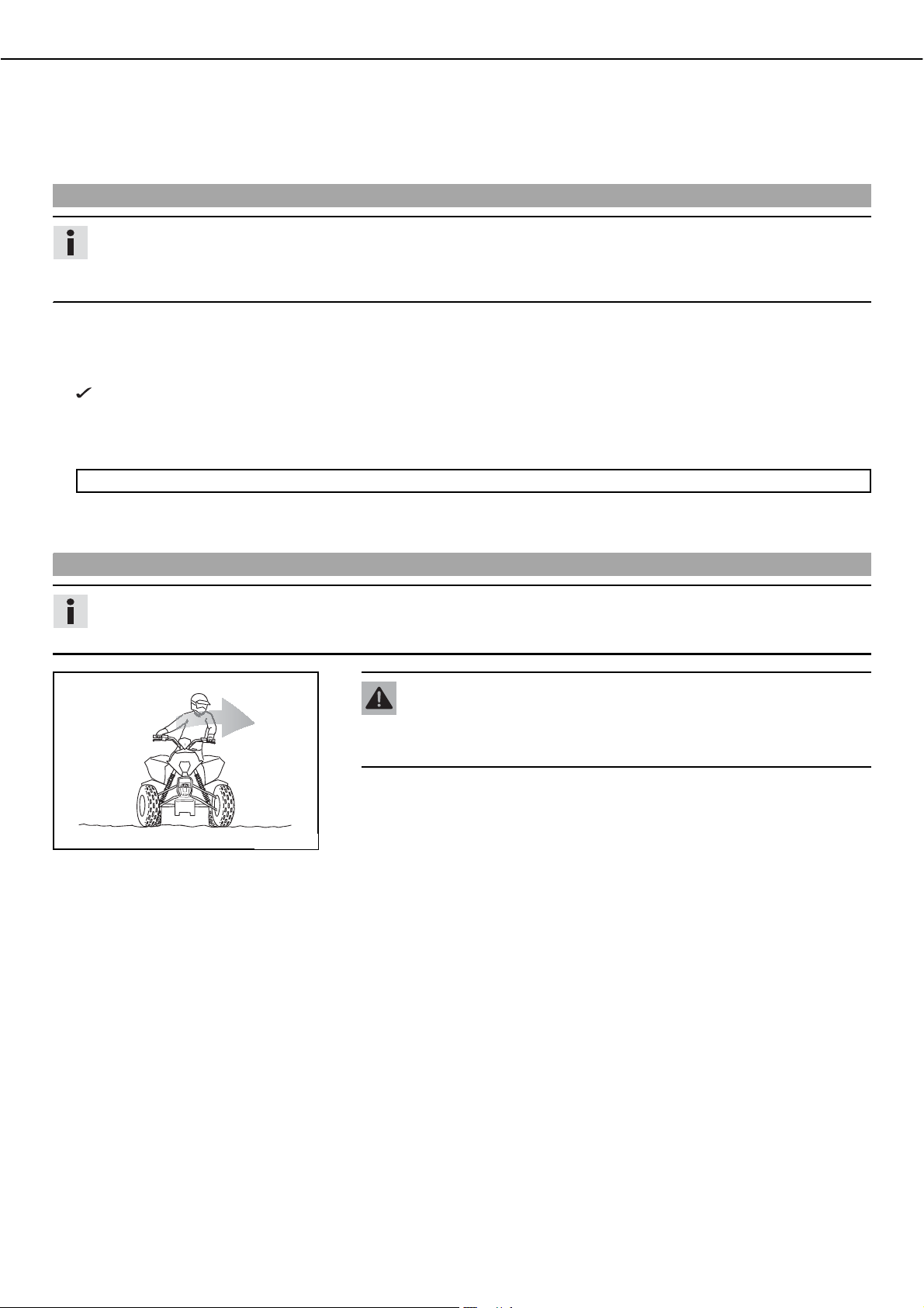
Warning
Danger of accidentsಘExcessive speed and turning at sharp angles can cause
the vehicle to roll over.
ದ Decrease your speed before entering into bends.
ದ Handling of the ATV is strongly influenced by shifts in the position of your body
weight. Always shift your body weight toward the inside of the bend and forward.
ದ The faster you ride and the tighter the bend, the more you need to shift your body
400300-01
weight.
ದ Always exert pressure on the footrest on the inside of the bend.
ದ Look in the direction of the bend while you are riding.
ದ The farther back you are sitting, the more the vehicle has the tendency to move
straight ahead. The farther forward you shift your weight, the more pressure is
applied to the front axle and the more easily the vehicle can take the bend.
Page 26
RIDING INSTRUCTIONS 24
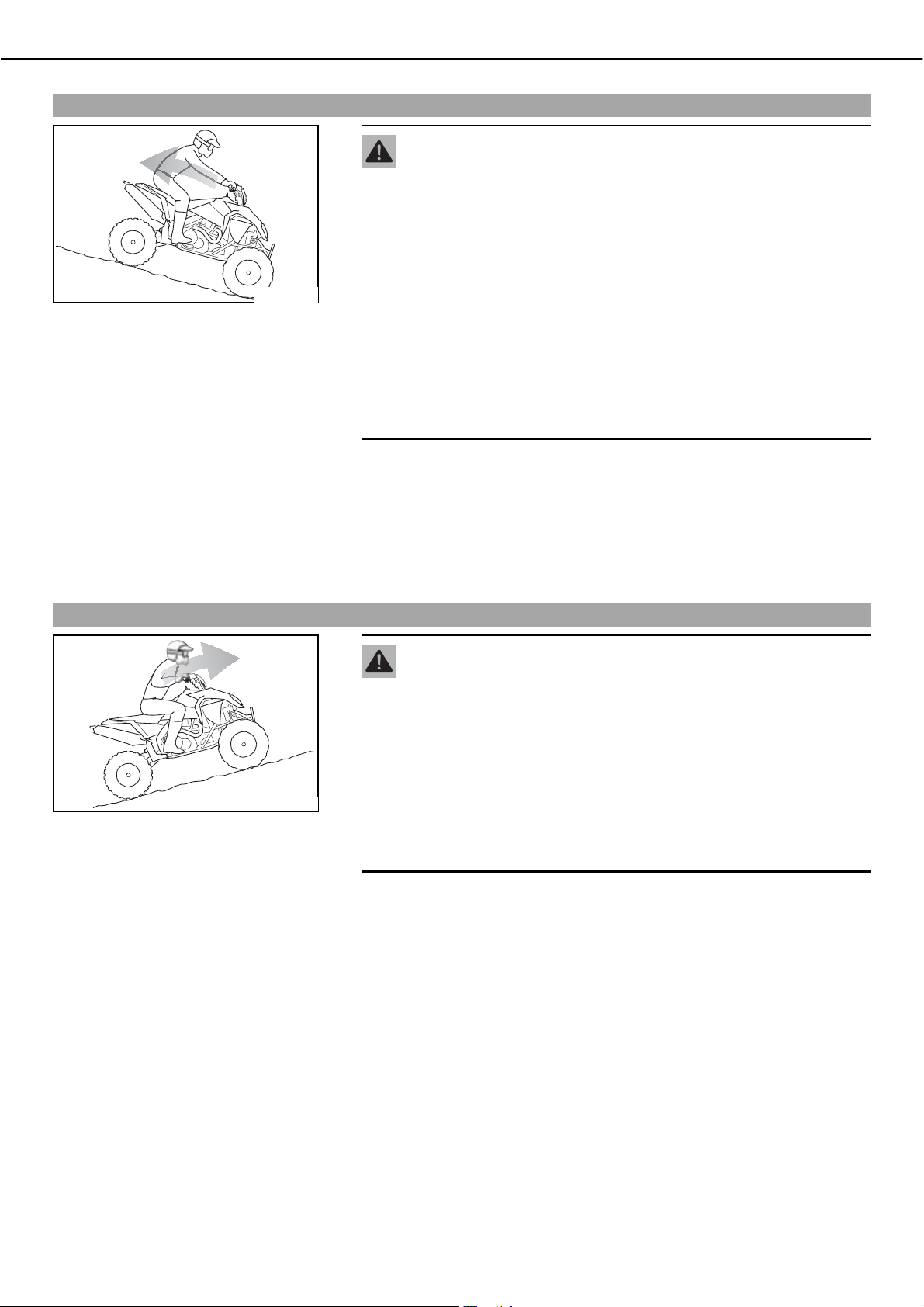
Riding downhill
Warning
Danger of accidentsಘDanger of accidents when riding on slopes.
ದ Always check the terrain before riding onto a slope.
ದ Never ride on a slope with an inclination of more than 25°.
ದ Never ride on a slope that exceeds your driving skills.
ದ Never ride down a slope backward. If you activate the rear brake, the
vehicle will roll over.
400297-01
ದ Always ride straight up or down a slope and never at a slant.
ದ Engage a gear with which you can ride all the way down the slope.
ದ Shift your body weight to the rear and ride cautiously without opening the throttle.
ದ Keep your vehicle speed and engine speed as constant as possible.
ದ Always be prepared to jump sideways off the vehicle should it go out of control.
ದ Brake by mainly applying the rear brake; the rear wheels should not become
ದ When you come to a standstill, always dismount from the vehicle and
turn it.
ದ Never ride on a slope with a slippery surface. The vehicle can easily go
out of control and roll over.
Note
Material damageಘDamage to vehicle after fall or rollover.
ದ Perform a vehicle check as is done everytime before you start to ride.
blocked.
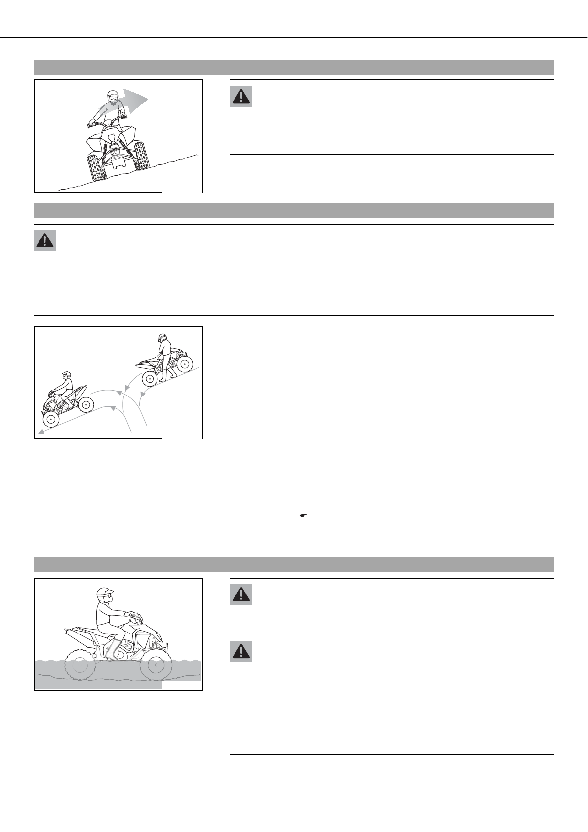
Riding uphill
400295-01
Warning
Danger of accidentsಘDanger of accidents when riding on slopes.
ದ Always check the terrain before riding onto a slope.
ದ Never ride on a slope with an inclination of more than 25°.
ದ Never ride on a slope that exceeds your driving skills.
ದ Never ride down a slope backward. If you activate the rear brake, the
vehicle will roll over.
ದ When you come to a standstill, always dismount from the vehicle and
turn it.
ದ Never ride on a slope with a slippery surface. The vehicle can easily go
out of control and roll over.
ದ Always ride straight up or down a slope and never at a slant.
ದ Engage a gear with which you can ride all the way up the slope. Shifting on the
slope can cause the vehicle to roll over.
ದ Shift your body weight to the front and ride cautiously.
ದ Keep your vehicle speed and engine speed as constant as possible.
ದ Always be prepared to jump sideways off the vehicle should it go out of control.
ದ Drive slowly over hilltops to give yourself the opportunity to react to obstacles and
changes in terrain.
ದ If the vehicle comes to a stop, immediately activate both brakes to prevent the
vehicle from rolling backward. Dismount from the vehicle and turn it.
Page 27
RIDING INSTRUCTIONS 25
Riding perpendicular to the slope
Warning
Danger of accidentsಘWhen riding perpendicular to a slope, the vehicle can
tip easily and roll over.
ದ Avoid riding perpendicular to the slope if possible.
ದ Ride slowly and shift you weight toward the slope.
ದ If the vehicle starts to tip over, steer it downhill and dismount immediately to the
uphill side.
400299-01
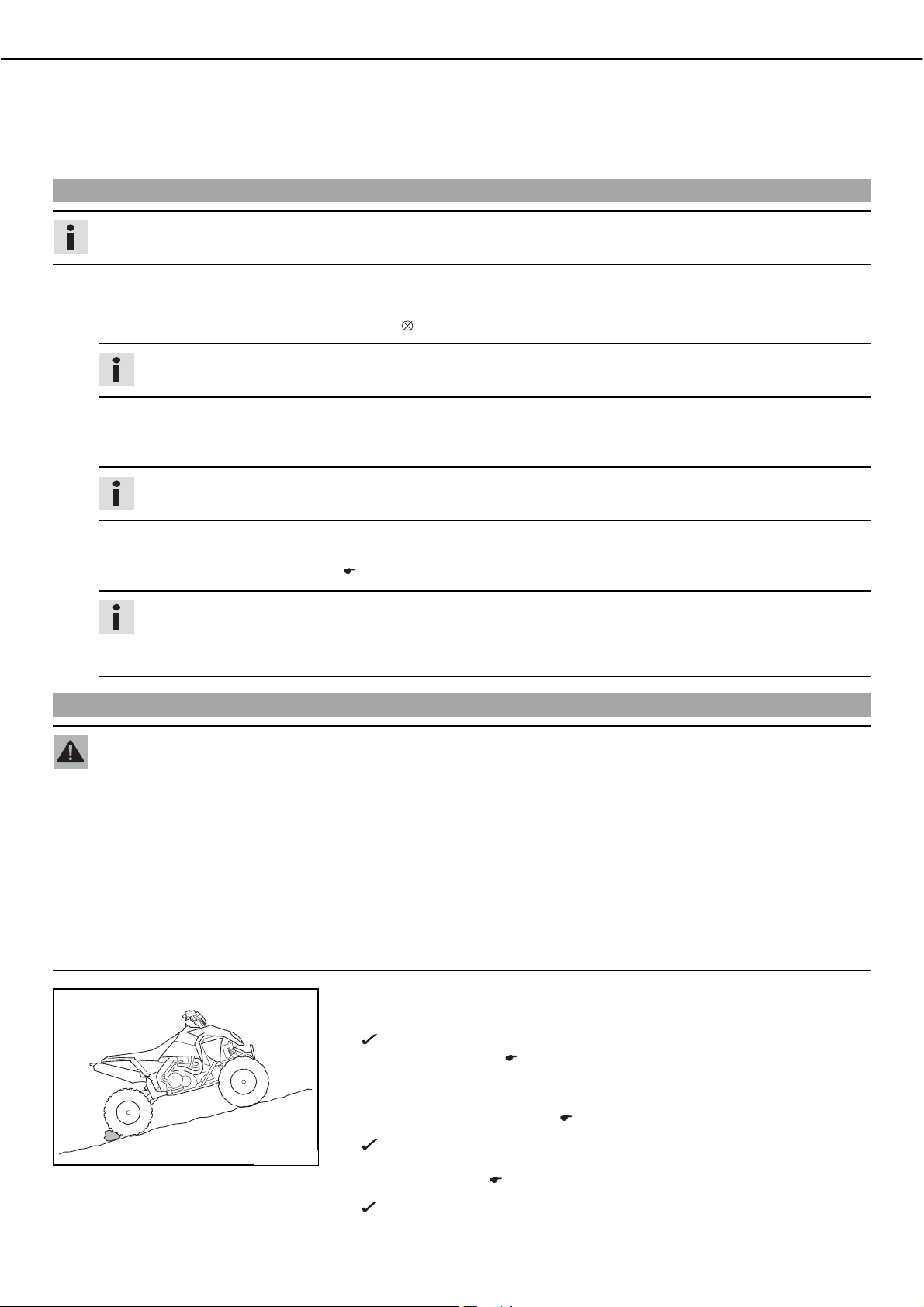
Turning on slopes
Warning
Danger of accidentsಘDanger of accidents from turning the vehicle on a slope.
ದ Never ride down a slope backward. The vehicle can roll over easily.
ದ Always position yourself next to the vehicle in a location where you cannot be caught by a wheel.
ದ When turning on a slope, always stand on the uphill side of the vehicle to avoid injury should the vehicle tip.
ದ If the slope is too steep or slippery to turn the vehicle, you should leave it where it is and get assistance in retrieving it.
Riding through water
400298-01
ದ If you come to a stop on a slope with your vehicle, dismount from the vehicle and
turn it.
ದ Switch off the engine and activate the parking brake.
ದ Dismount from the vehicle on the uphill side.
ದ Switch the transmission to neutral and stand next to the vehicle.
ದ Grasp the handlebar with both hands, release the parking brake and carefully
release the front brake.
ದ Let the vehicle roll downhill carefully until you reach a location where you can turn
it. Control its speed using the front brake.
ದ To turn the vehicle, steer it to the side. When doing so, you should always stand on
the uphill side and apply pressure to the footrest on the uphill side.
ದ When the vehicle is standing perpendicular to the slope or slightly downhill, acti-
vate the parking brake.
ದ Mount the vehicle, start the engine, pull the clutch lever and engage 1st gear. Cau-
tiously release the parking brake and ride down the hill in 1st gear.
ದ Riding downhill. ( P. 24)
ದ If you lose control over the vehicle, you should get away from the vehicle as fast as
possible.
Warning
Danger of accidentsಘThe vehicle can roll over when riding through deep
water with a strong current.
ದ Avoid riding through deep water with a strong current.
400302-01
Warning
Danger of accidentsಘReduced braking due to wet or dirty brakes.
ದ Clean or dry dirty or wet brakes by riding and braking gently.
Note
Engine failureಘWhen riding through deep water, water can enter into the engine
through the air filter and cause engine damage.
ದ Only ride through water if it reaches no higher than the upper edge of the
footrest.
ದ Before riding through water, determine the depth and current of the water.
ದ Ride slowly and negotiate around obstacles.
Page 28
RIDING INSTRUCTIONS 26
ದ After riding through water, dry the brakes by lightly activating both brakes until nor-
mal braking power is available again.
ದ If the vehicle becomes submerged, an authorized KTM workshop must perform a
thorough check and comprehensive service.. Do not start the engine.
Switching off the engine
Info
There are three ways to switch off the engine.
Alternativeb1
Switch off the engine using the ignition key.
ದ Turn the key in the ignition switch to thebpositionb .
Info
All power-consuming components are switched off.
Alternativeb2
Switch off the engine using the ENG.bSTOPbswitch.
ದ Press thebENG.bSTOPbswitch into thebOFF position.
Info
All power-consuming components are switched off.
Alternativeb3
Switch off the engine using the emergency OFF switch with a rip cord.
ದ Pull off the clipb
. (Figureb100010-10b P. 16)
Info
When the engine is switched off using the emergency OFF switch, the power-consuming components are not switched
off. All power-consuming components that are switched on (head lights, tail light, CDI, etc.) continue consuming electricity. This uses battery power and causes it to discharge.
Stopping, parking
Warning
Danger of burnsಘSome vehicle components get very hot when the machine is driven.
ದ Do not touch hot components such as exhaust system, radiator, engine, shock absorber and brakes. Allow these compo-
nents to cool down before starting work on them.
Note
Danger of damageಘDanger of damage from accidental rolling of vehicle.
ದ Park the vehicle on a surface that is as horizontal as possible and activate the parking brake.
Note
Fire hazardಘSome components (engine, radiator and exhaust system) get very hot when the engine is running.
ದ Do not place the vehicle where there are flammable or explosive substances.
400296-01
ದ Stop the vehicle and park it on a surface that is as horizontal as possible.
ದ Shift gear to neutral.
The green idling speed indicator lamp N lights up.
ದ Switch off the engine. ( P. 26)
ದ Remove the ignition key and the clip from the emergency OFF switch.
ದ Pull the hand brake lever, push the locking pawlb
brake lever. (Figureb100006-10b P. 14)
The front wheels are blocked.
ದ Turn the handleb
(Figureb100013-10b P. 16)
No more fuel flows from the tank to the carburetor.
ದ If the vehicle must be parked on an incline, additionally secure the rear wheels
against rolling (see illustration).
of the fuel tap to the OFF position.
down and release the hand
Page 29
RIDING INSTRUCTIONS 27
Refueling
Danger
Fire hazardಘFuel can easily catch fire.
ದ Never fill up the vehicle near open flames or burning cigarettes, and always switch off the engine first. Be careful that no
fuel is spilt, especially on hot vehicle components. Clean up spilt fuel immediately.
ದ Fuel in the fuel tank expands when warm and can escape if the tank is overfilled. See specifications on filling up with fuel.
Warning
Danger of poisoningಘFuel is poisonous and a health hazard.
ದ Avoid contact between fuel and skin, eyes and clothing. Do not inhale fuel vapors. If fuel gets into your eyes, rinse imme-
diately with water and contact a doctor. Wash affected skin areas immediately with soap and water. If fuel is swallowed,
contact a doctor immediately. Change clothing that has come into contact with fuel.
Warning
Environmental hazardಘImproper handling of fuel is a danger to the environment.
ದ Do not allow fuel to get into the ground water, the ground, or the sewage system.
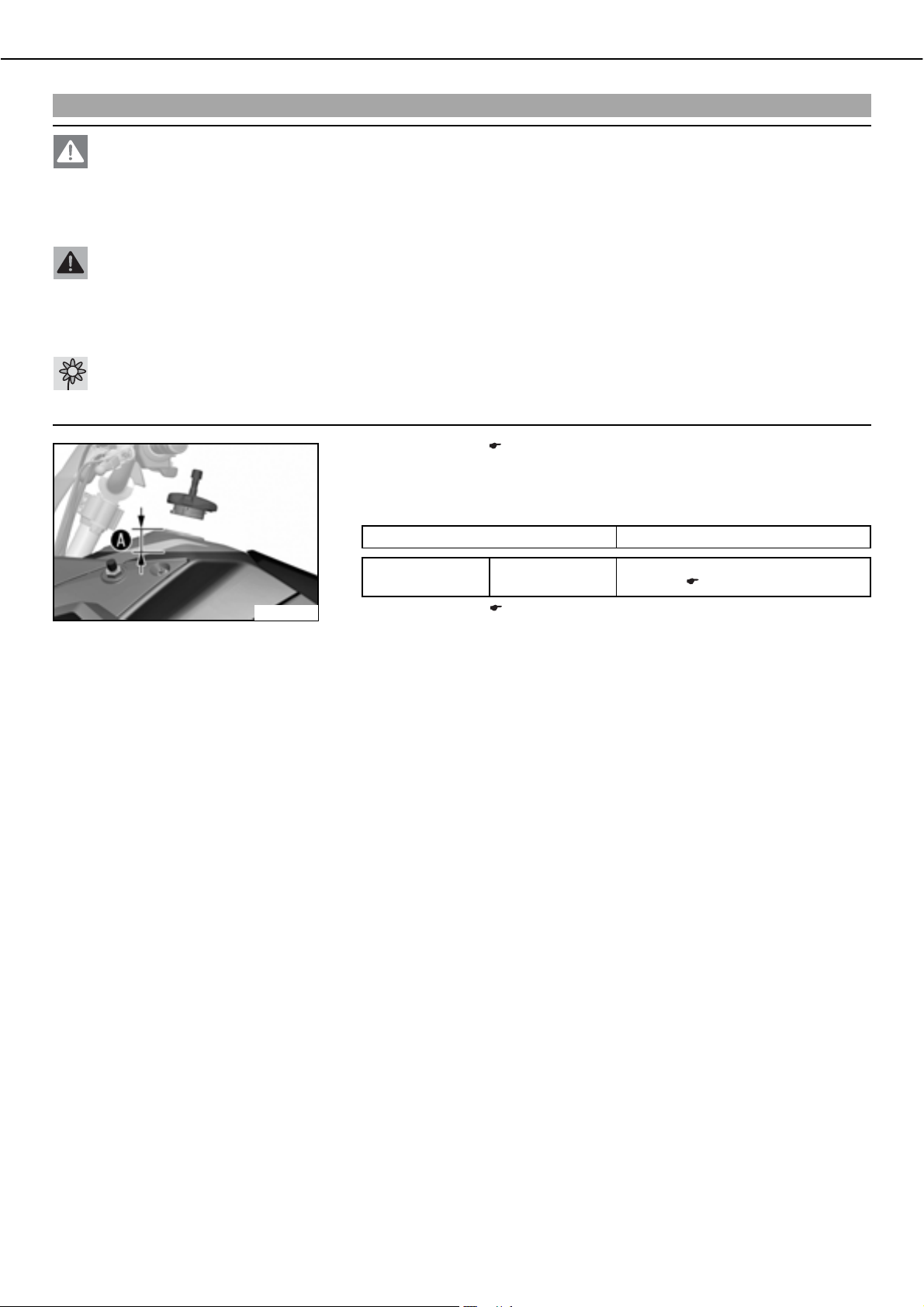
ದ Open the filler cap. ( P. 16)
ದ Switch off the engine.
ದ Fill the fuel tank with fuel up to measurementb
Specification
Measurement ofb
35bmm (1.38bin)
.
400287-10
Tank capacity 13.4bl
(3.54bUSbgal)
ದ Close the filler cap. ( P. 16)
Super unleaded (ROZ 95 / RON 95 /
PON 91) ( P. 95)
Page 30
GREASING AND SERVICE TABLE 28
*5($6,1*$1'6(59,&( 7$%/(
Important maintenance work to be carried out by an authorized KTM workshop.
S3N S15A S30A
Engine
Carburetor Check carburetor connection boots for cracks and leakage. • •
Attachments Check the cooling system for leakage. • • •
Brakes Check the front brake linings. ( P. 49) • • •
Chassis Check shock absorbers for cracks and proper functioning. • • •
Wheels Check rim run-out. • • •
Change the engine oil and oil filter, clean the oil screens.b
Replace spark plug. •
Check and adjust valve clearance. • • •
Check engine mounting screws for tightness. • • •
Clean spark plug connectors and check for tightness. • • •
Check shift lever screw for tightness. • • •
Check vent hoses for damage and routing without sharp bends. • • •
Check idle. •••
Check the antifreeze and coolant level. ( P. 67) • • •
Check the exhaust system for leakage and looseness. • •
Check Bowden cables for damage, smooth operation and routing without sharp
bends.
Check the fluid level of the hydraulic clutch. ( P. 66) • • •
Clean the air filter.b
Check cables for damage and routing without sharp bends. • •
Check that the electrical equipment is functioning properly. • • •
Check the headlamp setting. • •
Check speed limitation in reverse gear. • • •
Check the rear brake linings. ( P. 54) • • •
Check the brake discs. ( P. 47) • • •
Check the front brake fluid level. ( P. 48) • • •
Check the rear brake fluid level. ( P. 52) • • •
Check brake lines for damage and leakage. • • •
Check the free play of the hand brake lever. ( P. 48) • • •
Check the free play of the foot brake lever. ( P. 52) • • •
Check brake system function. • • •
Check screws and guide bolts of brake system for tightness. • • •
Check the steering column bearing for wear and smooth operation. • • •
Clean and grease bearing and sealing elements of steering column. • • •
Check steering for smooth operation and play. • • •
Check the bearing of the handlebar bridge of excessive play. • • •
Check tie rods and tie rod ends for damage and play. • • •
Check front wheel suspension for wear and tightness. • • •
Check that front and rear wheel hubs are tight. • • •
Check swingarm bearing. ••
Check the bearing of the rear axle for play. • • •
Grease the rear wheel eccentric element. ( P. 47) • •
Check all screws to see if they are tight. • • •
Check the tire condition. ( P. 57) • • •
Checking the tire air pressure. ( P. 57) • • •
Check the chain wear. ( P. 46) • • •
Check the chain tension. ( P. 45) • • •
Clean the chain. ( P. 45) • • •
Check front wheel bearing for play. • • •
x ( P. 66)
x ( P. 73)
•••
•••
•••
S3N: After 3 service hours - corresponds to about 21 liters of fuel
Page 31

GREASING AND SERVICE TABLE 29
S15A: Every 15 service hours - corresponds to about 105 liters of fuel / after every race
S30A: Every 30 service hours - corresponds to about 210 liters of fuel
Important maintenance work to be carried out by an authorized KTM workshop. (as additional order)
Competition use Hobby use J1A J2A
S15A S30A S45A S30A S60A S90A
Carry out a complete shock absorber service. •
Clean and adjust carburetor. ••
Treat electric contacts with contact spray. ••
Change hydraulic clutch fluid. ••
Change brake fluid. ••
Clean spark arrestor. ••
Check wear of clutch discs. • • • • • •
Check long clutch springs. • •
Check clutch slave cylinder for dents. • •
Check outer clutch hub for dents. • •
Check cylinder and piston wear. • •
Check camshaft wear. (visual check) • •
Change the camshaft bearing support. • •
Check wear of valve spring seat. • •
Check wear of valve guides. • •
Check valves. • •
Check valve springs. • •
Check the radial clearance of the rocker arm rollers. • •
Measure length of timing chain. • •
Check the timing-chain tensioner function. • •
Check crankshaft and crankshaft journal for run-out. • •
Change conrod bearing. • •
Change the crankshaft main bearing. • •
Change the balancer bearing. • •
Check wear of all transmission components including
shafts and bearings.
Check long bypass valve spring. • •
Change glass fiber yarn filling of main silencer. • •
Replace foot brake cylinder seals. • •
Check carburetor components. • •
••
S15A: Every 15 service hours - corresponds to about 105 liters of fuel / after every race
S30A: Every 30 service hours - corresponds to about 210 liters of fuel
S45A: Every 45 service hours - corresponds to about 315 liters of fuel
S60A: Every 60 service hours - corresponds to about 420 liters of fuel
S90A: Every 90 service hours - corresponds to about 630 liters of fuel
J1A: annually
J2A: every 2 years
Important checks and maintenance work to be carried out by the rider.
Check the engine oil level. ( P. 72) •
Check the front brake fluid level. ( P. 48) •
Check the rear brake fluid level. ( P. 52) •
Check the front brake linings. ( P. 49) •
Check the rear brake linings. ( P. 54) •
Check and adjust Bowden cables. •
Clean the chain. ( P. 45) •
Check the chain tension. ( P. 45) •
NB1A
Page 32

GREASING AND SERVICE TABLE 30
NB1A
Check the chain wear. ( P. 46) •
Check rear sprocket / engine sprocket for wear. ( P. 45) •
Clean the air filter.b
Checking the tire air pressure. ( P. 57) •
Check the tire condition. ( P. 57) •
Check the coolant level. ( P. 68) •
Check that all operating elements for smooth operation. •
Check braking force (incl. parking brake). •
Check all screws, nuts and hose clamps regularly for tightness. •
NB1A: Depending on conditions of use according to requirements.
x ( P. 66)
•
Page 33

MAINTENANCE ON CHASSIS AND ENGINE 31
0$,17(1$1&(21&+$66,6 $1'(1*,1(
Jacking up the vehicle
Note
Danger of damageಘDanger of damage from tipping of vehicle.
ದ Jack up the vehicle on a firm and horizontal surface. Use a flex-free work stand.
ದ Jack up the vehicle on the frame underneath the engine. The wheels must no
longer touch the ground.
ದ Secure the vehicle.
100054-10
Removing the vehicle from the work stand
Note
Danger of damageಘDanger of damage by the vehicle running away or falling over.
ದ Always place the vehicle on a firm and even surface.
ದ Lower the vehicle.
ದ Remove the work stand.
Basic information on changing the chassis settings
The standard setting of the chassis is the result of many fine tuning tests. It is laid out for the weight of the average rider (with a full
set of protective clothing) and for a sporty driving style.
Standard rider weight 70… 80bkg (154… 176blb.)
By making a variety of adjustments to the chassis, you can set it to better match your body weight and riding style.
The left and right front shock absorbers should have the same settings.
If your weight is above or below the range, you have to adjust the standard setting of the suspension components accordingly.
Small weight differences can be compensated by adjusting the spring preload, but in the case of large weight differences, the springs
must be replaced.
Tip
When changing the chassis settings, always start with the standard setting.
Between test rides, always change only one setting. This will enable you to better assess the effect of the setting on vehicle
handling.
Do not make radical changes to the settings; proceed in small steps instead. Even small changes can have a large impact on
vehicle handling.
Adjusting front shock absorber compression damping
Danger
Danger of accidentsಘThe shock absorber is under high pressure.
ದ The shock absorber is filled with highly compressed nitrogen, so never dismantle the shock absorber or carry out any main-
tenance on it yourself.
Warning
Danger of accidentsಘDo not make any radical changes to the adjustment of the shock absorbers.
ದ Only make adjustments within the recommended range.
Info
The compression damping setting has an impact on the compression of the shock absorber.
Page 34

MAINTENANCE ON CHASSIS AND ENGINE 32
ದ Turn the adjusting wheelb clockwise until it stops.
ದ Turn back counterclockwise the number of clicks corresponding to the shock
absorber type.
Specification
Compression damping
Standard 14bclicks
Maximum deviation from standard
value
100027-10
Tip
Experience has shown that settings outside of this range are detrimental to
vehicle handling. When changing the chassis settings, always start with the
standard setting.
Info
Turn clockwise to increase damping, turn counterclockwise to reduce suspension damping.
The left and right shock absorbers should have the same settings.
Adjusting front shock absorber rebound damping
Danger
Danger of accidentsಘThe shock absorber is under high pressure.
ದ The shock absorber is filled with highly compressed nitrogen, so never dismantle the shock absorber or carry out any main-
tenance on it yourself.
5… 5bclicks
Warning
Danger of accidentsಘDo not make any radical changes to the adjustment of the shock absorbers.
ದ Only make adjustments within the recommended range.
Info
The rebound damping setting has an impact on the compression of the shock absorber.
ದ Turn the adjusting screwb clockwise until it stops.
ದ Turn back counterclockwise the number of clicks corresponding to the shock
absorber type.
Specification
Rebound damping
Standard 20bclicks
Maximum deviation from standard
value
100028-10
5… 5bclicks
Tip
Experience has shown that settings outside of this range are detrimental to
vehicle handling. When changing the chassis settings, always start with the
standard setting.
Info
Turn clockwise to increase damping, turn counterclockwise to reduce suspension damping.
The left and right shock absorbers should have the same settings.
Page 35

0
MAINTENANCE ON CHASSIS AND ENGINE 33
Adjusting front shock absorber cross over
Danger
Danger of accidentsಘThe shock absorber is under high pressure.
ದ The shock absorber is filled with highly compressed nitrogen, so never dismantle the shock absorber or carry out any main-
tenance on it yourself.
Info
The cross over setting is used to adjust the suspension travel of the short (soft) spring.
Greater cross over makes the spring action at the front softer and the front of the vehicle lies lower. The suspension travel and
the progressive part of the long (hard) spring is not fully utilized.
Less cross over makes the spring action at the front harder and the front of the vehicle lies higher.
ದ Jack up the vehicle. ( P. 31)
ದ Clean the shock absorber thoroughly.
ದ Loosen the adjusting ringb. Suitable toolsb are available from an authorized
KTM workshop.
Hook wrench, Öhlins (83019001000)
100084-10
ದ The cross over settingb is measured between the sliding bushingb and the collar
of the spring retainerb
00
4
Specification
ದ Change the settings accordingly and lock the adjusting ring.
BB
3
Adjusting front shock absorber spring preload
400348-11
ದ Remove the vehicle from the work stand. ( P. 31)
Cross over 17±1.5bmm (0.67±0.059bin)
Info
The sliding bushing is made of plastic. Therefore, do not lock it too tightly
to avoid damaging the thread.
The left and right shock absorbers should have the same settings.
.
Danger
Danger of accidentsಘThe shock absorber is under high pressure.
ದ The shock absorber is filled with highly compressed nitrogen, so never dismantle the shock absorber or carry out any main-
tenance on it yourself.
Warning
Danger of accidentsಘDo not make any radical changes to the adjustment of the shock absorbers.
ದ Make adjustments in small steps only.
Info
Increasing the spring preload raises the center of gravity of the vehicle. This can have a large impact on vehicle handling.
Tip
Before you change the spring preload, make a note of the groove in which the securing clip is positioned. When making adjustments, always start from the standard setting.
ದ Jack up the vehicle. ( P. 31)
ದ Clean the shock absorber thoroughly.
Page 36

MAINTENANCE ON CHASSIS AND ENGINE 34
ದ Press the spring pack and the spring retainerb down to make the securing clipb
accessible.
ದ Using pliers, position the securing clip in one of the upper grooves. Do not over-
strain the securing clip.
ದ Release the spring pack and measure the length of the unloaded spring pack.
100083-10
ದ Press together the spring pack, position the securing clip in the corresponding
groove and release the spring pack.
Specification
00AA
Clip position, spring preload
Standard 7 th position from top
Corresponds to a spring preload of 5bmm (0.2bin)
Info
The spring preloadb is the difference in length between the spring pack
when it is unloaded and when it is installed.
The securing clip must be positioned entirely within the cut-out of the
spring retainer.
The spring pack should never be installed loosely (without preload). The
standard setting is the lowest permissible spring preload. Therefore, you can
only increase the spring preload.
If you increase the spring preload, you should also slightly increase the
rebound damping.
The left and right shock absorbers should have the same settings.
400347-10
Adjusting rear shock absorber compression damping
ದ Remove the vehicle from the work stand. ( P. 31)
Danger
Danger of accidentsಘThe shock absorber is under high pressure.
ದ The shock absorber is filled with highly compressed nitrogen, so never dismantle the shock absorber or carry out any main-
tenance on it yourself.
Warning
Danger of accidentsಘDo not make any radical changes to the adjustment of the shock absorbers.
ದ Only make adjustments within the recommended range.
Info
The compression damping setting has an impact on the compression of the shock absorber.
ದ Turn the adjusting wheelb clockwise until it stops.
100080-10
Page 37

MAINTENANCE ON CHASSIS AND ENGINE 35
ದ Turn back counterclockwise the number of clicks corresponding to the shock
absorber type.
Specification
Compression damping
Standard 15bclicks
Maximum deviation from standard
value
Tip
Experience has shown that settings outside of this range are detrimental to
vehicle handling. When changing the chassis settings, always start with the
standard setting.
Info
Turn clockwise to increase damping, turn counterclockwise to reduce suspension damping.
Adjusting rear shock absorber rebound damping
Danger
Danger of accidentsಘThe shock absorber is under high pressure.
ದ The shock absorber is filled with highly compressed nitrogen, so never dismantle the shock absorber or carry out any main-
tenance on it yourself.
5… 5bclicks
Warning
Danger of accidentsಘDo not make any radical changes to the adjustment of the shock absorbers.
ದ Only make adjustments within the recommended range.
Info
The rebound damping setting has an impact on the compression of the shock absorber.
ದ Turn the adjusting wheelb to the right until it stops.
ದ Turn back to the left the number of clicks corresponding to the shock absorber
type.
Specification
Rebound damping
Standard 15bclicks
Maximum deviation from standard
value
100081-10
5… 5bclicks
Tip
Experience has shown that settings outside of this range are detrimental to
vehicle handling. When changing the chassis settings, always start with the
standard setting.
Info
Turning to the right increases damping, while turning to the left lessens
damping.
Page 38

MAINTENANCE ON CHASSIS AND ENGINE 36
Adjusting rear shock absorber spring preloadbx
Danger
Danger of accidentsಘThe shock absorber is under high pressure.
ದ The shock absorber is filled with highly compressed nitrogen, so never dismantle the shock absorber or carry out any main-
tenance on it yourself.
Warning
Danger of accidentsಘDo not make any radical changes to the adjustment of the shock absorbers.
ದ Make adjustments in small steps only.
Info
Increasing the spring preload raises the center of gravity of the vehicle. This can have a large impact on vehicle handling.
Tip
Before changing the spring preload, make a note of the present setting, e.g., by measuring the length of the spring.
100082-10
ದ
Remove the rear shock absorber.b
ದ After removing the shock absorber, clean it thoroughly.
ದ Loosen the lock nutb. Hold adjusting ringb while doing so. Suitable toolsb are
available from an authorized KTM workshop.
Hook wrench (83019002000)
x ( P. 37)
Info
Do not loosen the lock nutb at the top of the shock absorber.
ದ Turn adjusting ring until the spring is no longer under tension.
ದ Measure the overall spring length when not under tension.
Info
The spring preloadb is the difference in length between the spring when it
is unloaded and when it is installed.
ದ Tighten the spring by turning adjusting ring to measurement .
Specification
Spring preload
Standard 3bmm (0.12bin)
ದ Tighten the lock nut and the adjusting ring.
400363-11
Info
The adjusting ringb is made of plastic. Therefore, do not lock the adjusting
ring too tightly to avoid damaging the thread.
If you increase the spring preload, you should also slightly increase the
rebound damping.
ದ
Install the rear shock absorber.b
x ( P. 37)
Page 39

MAINTENANCE ON CHASSIS AND ENGINE 37
Removing the rear shock absorberbx
ದ Jack up the vehicle. ( P. 31)
ದ Remove the rear fender. ( P. 63)
Note
Danger of damageಘThe chain sliding piece and frame can be damaged from incor-
rect handling.
ದ When removing the rear shock absorber, secure the swingarm with a tension
belt to prevent it from swinging down further.
100078-10
Installing the rear shock absorberbx
ದ Attach the swingarm to the subframe with a tension beltb
to relieve the shock
absorber.
ದ Remove the bottom screw of the shock absorber.
Tip
Press the screw out of the swingarm with a screw driver while moving the
tension belt.
ದ Remove the top screwb
absorber out of the vehicle toward the rear.
ದ Check parts for damage and wear. Replace damaged or worn parts.
ದ Position the shock absorber in the vehicle with the reservoir on the right. Mount
and tighten the top screwb
Specification
Screw, rear top shock absorber M12 60bNm
ದ Position the shock absorber in the swingarm. Mount and tighten the bottom screw.
Specification
Screw, rear bottom shock absorber M12 70bNm
of the shock absorber and carefully remove the shock
.
(44.3blbfbft)
(51.6blbfbft)
Toe, checkingbx
ದ Remove the tension belt.
ದ Install the rear fender. ( P. 64)
ದ Remove the vehicle from the work stand. ( P. 31)
100079-10
ದ Park the vehicle on a horizontal surface.
ದ Check the tire condition. ( P. 57)
ದ Checking the tire air pressure. ( P. 57)
ದ Check the chassis parts for damage, play and wear.
Page 40

MAINTENANCE ON CHASSIS AND ENGINE 38
ದ Load the vehicle with the specified weight.
Specification
Standard rider weight 70… 80bkg (154… 176blb.)
ದ Turn the steering to the straight-ahead position and fix it.
Steering fixing for straight-ahead position (83019015000)
500228-01
ದ Measure distancesb andb.
» If distancesb
ದ
Adjust the toe.b
ದ Measure distancesb
Specification
Toe
Front 0bmm (0bin)
andb are not equal:
x ( P. 38)
andb.
Info
The toe is the difference in length between distancesb andb by which the wheels are spaced at the front or rear when
driving straight ahead. The distance is measured at the height of the wheel center from rim flange to rim flange.
» If the toe does not meet specifications:
ದ
Adjust the toe.b
Adjusting the toebx
x ( P. 38)
400333-10
ದ Park the vehicle on a horizontal surface.
ದ Check the tire condition. ( P. 57)
ದ Checking the tire air pressure. ( P. 57)
ದ Check the chassis parts for damage, play and wear. Replace damaged or worn
parts.
Page 41

MAINTENANCE ON CHASSIS AND ENGINE 39
ದ Load the vehicle with the specified weight.
Specification
Standard rider weight 70… 80bkg (154… 176blb.)
ದ Turn the steering to the straight-ahead position and fix it.
Steering fixing for straight-ahead position (83019015000)
500228-01
400333-11
ದ Loosen nutsb andb.
ದ Adjust the distancesb
ದ Adjust the distancesb
Specification
Toe
Front 0bmm (0bin)
andb to the same value by rotating the tie rodsb.
andb to the specified value by evenly rotating the tie rodsb.
Info
The toe is the difference in length between distancesb andb by which the wheels are spaced at the front or rear when
driving straight ahead. The distance is measured at the height of the wheel center from rim flange to rim flange.
ದ Tighten nutsb
Specification
Lock nut, tie rod, outside M12x1,25 20bNm (14.8blbfbft)
Lock nut, tie rod, inside M12LHx1,25 20bNm (14.8blbfbft)
andb.
Info
The tie rodsb must still be freely movable.
Page 42

MAINTENANCE ON CHASSIS AND ENGINE 40
Checking/adjusting camberbx
Info
The left and right camber should have the same settings.
The operations are the same on the left and right.
ದ Jack up the vehicle. ( P. 31)
ದ Loosen nutsb.
600128-10
ದ Remove screwsb with bushingsb.
ದ Check parts for damage and wear. Replace damaged or worn parts.
600126-10
600127-10
600126-10
ದ Insert the toolb in the heim joint and clip onto the A-arm.
Camber gauge (83019014000)
ದ Check the camber on both heim joints.
» If the markingb
ದ Turn the toolb
is not aligned with the top edge of the A-arm:
with the heim joint in steps of 180° until the marking is in
line with the top edge of the A-arm.
ದ Remove the toolb
.
ದ Position the A-arm with the bushingsb. Mount and tighten screwsb.
Specification
Screw, A-arm top M10x52 45bNm
(33.2blbfbft)
ದ Align the heim joint at right angles to the screwsb and tighten the nutb.
Specification
Nut, A-arm top M12x1,25 30bNm
(22.1blbfbft)
600128-10
Info
All four heim joints must be checked and adjusted if necessary.
ದ Remove the vehicle from the work stand. ( P. 31)
Page 43

MAINTENANCE ON CHASSIS AND ENGINE 41
Fork offset
The fork offset has an impact on the handling of the vehicle.
The fork offset can optionally be adjusted.
Fork offset is defined as the slanted position of the swivel axis in the direction of the longitudinal axis of the vehicle in relation to a
vertical line to the driving surface.
When both sleeves are installed in front of the A-arms, the fork offset increases. This enhances driving stability on fast raceways.
When both bushings are installed behind the A-arms, the fork offset decreases. This improves handling in bends.
Upon delivery one bushing is installed in front of the A-arm and one behind it.
Adjusting the fork offsetbx
Info
The left and right fork offset should have the same settings.
The operations are the same on the left and right.
ದ Jack up the vehicle. ( P. 31)
ದ Remove screwsb with bushingsb.
ದ Check parts for damage and wear. Replace damaged or worn parts.
ದ Place the A-arm with the bushingsb
screwsb
.
Specification
Screw, A-arm top M10x52 45bNm
in the desired position. Mount and tighten
(33.2blbfbft)
600126-11
Toe width of rear axle
The toe widthb can be adjusted by installed the spacing sleeve in various ways.
ದ Remove the vehicle from the work stand. ( P. 31)
Difference between nar-
76bmm (2.99bin)
row/wide toe
100101-10
Adjusting the toe width of rear axlebx
Warning
Danger of accidentsಘChanges to the chassis can strongly influence how the vehicle handles.
ದ After making changes, always ride slowly to allow yourself to respond to vehicle handling.
ದ Engage 1st gear.
ದ Loosen nutsb of the wheel hubs on both sides.
ದ Jack up the vehicle. ( P. 31)
ದ Remove the nutsb
ದ Check parts for damage and wear. Replace damaged or worn parts.
on both sides and take all parts off of the rear axle.
100102-10
Info
The left and right toe width should have the same settings.
Page 44

MAINTENANCE ON CHASSIS AND ENGINE 42
Setting a narrow toe width:
00
22
0033
0022
11
00
00
11
0033
100103-10
100104-10
ದ Mount the wheel hubb
ದ Mount the conical ringb
ದ Mount the spacing sleeveb
ದ Mount the washer and the new self-locking nut.
Setting a wide toe width:
ದ Mount the spacing sleeveb
ದ Mount the conical ringb
ದ Mount the wheel hubb
ದ Mount the washer and the new self-locking nut.
ದ Remove the vehicle from the work stand. ( P. 31)
ದ Tighten nutsb
Specification
Nut, rear wheel hub M18x1,5 130bNm
on both sides.
.
with the cone facing outward.
with the cone facing inward.
with the cone facing inward.
with the cone facing outward.
.
(95.9blbfbft)
Handlebar position
100102-10
ದ Shift gear to neutral.
The handlebar position can be adjusted 4-fold by turning the handlebar supportb and
the handlebar supportb
The holes on the handlebar support are placed at a distance ofb
Distanceb
The holes on the handlebar bridge are placed at a distance ofb
Distanceb
between holes 3.5bmm (0.138bin)
between holes 7.5bmm (0.295bin)
.
from the center.
from the center.
100098-10
Page 45

MAINTENANCE ON CHASSIS AND ENGINE 43
Adjusting handlebar positionbx
ದ Pull the instrument support off the handlebar and swing it to the side.
Info
Protect the vehicle and its attachments from damage by covering them.
Do not bend the cables and lines.
100100-10
ದ Remove the four screwsb. Remove the handlebar clampsb, swing the handlebar
forward and set it down.
ದ Remove the nutsb
ದ Remove screwsb
ದ Remove screwsb
ದ Check parts for damage and wear. Replace damaged or worn parts.
ದ Place the handlebar bridgeb
Mount and tighten screwb
Specification
Screw, steering bridge M8 20bNm
and remove the handlebar supportb with the screws.
andb.
. Remove the handlebar bridgeb.
onto the steering column in the desired position.
.
(14.8blbfbft)
100099-10
ದ Mount and tighten screwb
Specification
Screw, steering column, top M20x1,5 25bNm
ದ Mount and tighten screwsb
Specification
Screw, steering bridge M8 20bNm
ದ Mount the handlebar supportb
new self-locking nutsb
Specification
Nut, handlebar support M10 45bNm
ದ Position the handlebar and fix it with the handlebar clampsb
screwsb
.
Specification
Screw, handlebar clamp M8 20bNm
.
.
in the desired position using the screws. Mount
and tighten.
Info
Make sure cables and wiring are positioned correctly.
ದ Position the instrument support on the handlebar.
(18.4blbfbft)
(14.8blbfbft)
(33.2blbfbft)
. Mount and tighten
(14.8blbfbft)
Checking play in gas Bowden cable
600142-10
ದ Move the handlebar to the straight-ahead position. Move the throttle lever back and
forth slightly to ascertain the play in the gas Bowden cableb
Specification
Play in gas Bowden cable 3… 5bmm (0.12… 0.2bin)
» If the gas Bowden cable play does not meet specifications:
ದ Adjust the play in the gas Bowden cable. ( P. 44)
.
Page 46

MAINTENANCE ON CHASSIS AND ENGINE 44
Danger
Danger of poisoningಘExhaust gases are poisonous and can result in uncon-
sciousness and/or death.
ದ When running the engine, always make sure there is sufficient ventila-
tion, and do not start or run the engine in a closed space.
ದ Start the engine and let it run idle. Move the handlebar to and fro over the entire
steering range.
The idle speed must not change.
» If the idle speed changes:
ದ Adjust the play in the gas Bowden cable. ( P. 44)
Adjusting play in gas Bowden cable
ದ Check gas Bowden cable route.
ದ Move the handlebar to the straight-ahead position.
ದ Loosen the nutb
cableb
.
Specification
Play in gas Bowden cable 3… 5bmm (0.12… 0.2bin)
and use the screwb to adjust the play in the gas Bowden
ದ Tighten nutb
600142-11
Checking the play in the Bowden cable using the reverse gear release lever
.
ದ Move the handlebar to the straight-ahead position. Move the reverse gear release
lever back and forth slightly to ascertain the play in the Bowden cableb
Specification
Play in the Bowden cable on the
reverse gear release lever
» If the Bowden cable play on the reverse gear release lever does not agree with
the specifications:
ದ Adjust the play in the Bowden cable using the reverse gear release lever.
600141-10
Adjusting the play in the Bowden cable using the reverse gear release lever
( P. 44)
ದ Check that the Bowden cable is correctly laid from the reverse gear release lever.
ದ Move the handlebar to the straight-ahead position.
ದ Release the nutb
and using the screwb, adjust the play of the Bowden cableb
on the reverse gear release lever.
Specification
Play in the Bowden cable on the
reverse gear release lever
.
10bmm (0.39bin)
10bmm (0.39bin)
600141-11
ದ Tighten nutb
.
Page 47

MAINTENANCE ON CHASSIS AND ENGINE 45
Checking chain dirt
ದ Check the chain for coarse dirt accumulation.
» If the chain is very dirty:
ದ Clean the chain. ( P. 45)
Cleaning the chain
Warning
Environmental hazardಘProblem materials cause environmental damage.
ದ Dispose of oil, grease, filters, fuel, cleaning substances, brake fluid, batteries, etc. according to regulations.
Info
The service life of the chain depends largely on its maintenance.
ದ Clean the chain regularly and then treat with chain spray.
Chain cleaner ( P. 97)
Offroad chain spray ( P. 97)
Checking the chain tension
Warning
Danger of accidentsಘDanger caused by incorrect chain tension.
ದ If the chain tension is too high, the components of the secondary power train (chain, engine sprocket, rear sprocket, bear-
ings in transmission and rear wheel eccentric element) are under additional load. Apart from premature wear, in extreme
cases the chain can rupture or the countershaft of the transmission can break. On the other hand, if the chain is loose,
it can fall off the engine sprocket or the rear sprocket and block the rear wheels or damage the engine. Check for correct
chain tension and adjust if necessary.
ದ Park the vehicle on a horizontal surface and shift gears to neutral.
ದ Push the upper chain section at the end of the chain sliding component upwards to
measure the chain tensionb
$.
Info
The lower chain section must be taut.
Chain wear is not always even, so you should repeat this measurement at
different chain positions.
Chain tension 140… 145bmm (5.51… 5.71bin)
100093-10
Checking rear sprocket / engine sprocket for wear
» If the chain tension does not meet specifications:
ದ Adjust the chain tension. ( P. 46)
ದ Check rear sprocket / engine sprocket for wear.
» If the rear sprocket / engine sprocket are worn:
ದ Replace the rear sprocket / engine sprocket.
400227-01
Info
When fitting the chain joint, always make sure that the closed side
of the joint faces forward (riding direction).
The engine sprocket, rear sprocket and chain should always be
replaced together.
ದ Check that the chain guides are tight.
Page 48

MAINTENANCE ON CHASSIS AND ENGINE 46
Checking chain wear
ದ Park the vehicle on a horizontal surface and shift gears to neutral.
ದ Pull the lower chain section with the specified weightb.
Specification
Chain-wear measuring weight 10… 15bkg (22… 33blb.)
ದ Measure the distanceb
of 18 chain links in the upper chain section.
Info
Chain wear is not always even, so you should repeat this measurement at
different chain positions.
Maximum distanceb
at the longest
272bmm (10.71bin)
chain section
» If the distanceb
is greater than the specified measurement:
ದ Replace the chain.
Info
When you replace the chain, you should also replace the rear
sprocket and engine sprocket.
New chains wear out faster on old, worn sprockets.
100096-10
Adjusting chain tension
Warning
Danger of accidentsಘDanger caused by incorrect chain tension.
ದ If the chain tension is too high, the components of the secondary power train (chain, engine sprocket, rear sprocket, bear-
ings in transmission and rear wheel eccentric element) are under additional load. Apart from premature wear, in extreme
cases the chain can rupture or the countershaft of the transmission can break. On the other hand, if the chain is loose,
it can fall off the engine sprocket or the rear sprocket and block the rear wheels or damage the engine. Check for correct
chain tension and adjust if necessary.
100093-10
ದ Park the vehicle on a horizontal surface and shift gears to neutral.
ದ Push the upper chain section at the end of the chain sliding component upwards to
measure the chain tensionb
$.
Info
The lower chain section must be taut.
Chain wear is not always even, so you should repeat this measurement at
different chain positions.
Page 49

MAINTENANCE ON CHASSIS AND ENGINE 47
ದ Loosen the screwsb by four turns.
Alternativeb1
ದ Insert the toolb
element.
Alternativeb2
ದ Use a special tool on the rear wheel eccentric.
Hook wrench (83019011000)
from the tool set into the holeb of the rear wheel eccentric
ದ To adjust the chain tensionb
100094-10
ದ Fully tighten screwsb
ದ Remove toolb
Greasing the rear wheel eccentric element
ದ Use a grease gun to fill the rear wheel eccentric element via the grease nippleb
$, use the special tool to slowly turn at the rear wheel
to rotate the rear wheel eccentric element forward or backward.
Specification
Chain tension 140… 145bmm (5.51… 5.71bin)
Info
Rotating the rear wheel eccentric element forward increases chain tension.
Rotating the rear wheel eccentric element backward reduces chain tension.
The rear wheel eccentric element should always be positioned such that the
grease nippleb
is visible. This ensures that the vehicle has the greatest
ground clearance.
.
Specification
Screw, rear wheel eccentric element M8 20bNm
(14.8blbfbft)
.
until grease emerges from the left shaft seal ringb.
Long-life grease ( P. 95)
100092-10
Checking brake discs
Warning
Danger of accidentsಘReduced braking due to worn brake discs.
ದ Worn brake discs should be replaced immediately in an authorized KTM workshop.
ದ Check the thickness of the front and rear brake discs at several places on the disc
to see if it conforms to measurementb
Info
Wear reduces the thickness of the brake disc around the area used by the
brake linings.
Wear limit of brake discs
Front 3.5bmm (0.138bin)
400362-10
Rear 3.5bmm (0.138bin)
» If the brake disc thickness is less than the specified value.
ದ Change the brake disc.
.
Page 50

MAINTENANCE ON CHASSIS AND ENGINE 48
Checking free play of hand brake lever
Warning
Danger of accidentsಘBrake system failure.
ದ If there is no free travel on the hand brake lever, pressure builds up on the front brake in the brake system. The front brake
can fail due to overheating. Adjust free travel on hand brake lever according to specifications.
ದ Push the hand brake lever forwards and check free play.b.
Free play of hand brake lever ุb3bmm (ุb0.12bin)
» If the free travel does not meet the specifications:
ದ Adjust the basic position of the handbrake lever. ( P. 48)
100088-10
Adjusting basic position of handbrake lever
ದ Adjust the basic setting of the handbrake lever to your hand size by turning adjust-
ing screwb
.
Info
Pull the brake lever forward and turn the adjusting screw.
Turn the adjusting screw clockwise to increase the distance between the
handbrake lever and the handlebar.
Turn the adjusting screw counterclockwise to decrease the distance between
the handbrake lever and the handlebar.
100052-10
The range of adjustment is limited.
Turn the adjusting screw by hand only, and do not apply any force.
Do not make any adjustments while riding!
ದ Check the free play of the hand brake lever. ( P. 48)
Checking front brake fluid level
Warning
Danger of accidentsಘBrake system failure.
ದ If the brake fluid level falls below the bottom of the viewer, this indicates a leakage in the brake system or worn-out brake
linings. Have the brake system checked in an authorized KTM workshop, and do not ride any further.
Warning
Danger of accidentsಘReduced braking due to old brake fluid.
ದ Have the front and rear brake fluid replaced according to the service plan in an authorized KTM workshop.
ದ Move the brake fluid reservoir mounted on the handlebar to a horizontal position.
ದ Check the brake fluid level in the viewerb
» When the brake fluid level has dropped below the bottom of the viewer:
ದ
Top up the brake fluid of the front brake.bx ( P. 49)
.
100035-10
Page 51

MAINTENANCE ON CHASSIS AND ENGINE 49
Topping up the front brake fluidbx
Warning
Danger of accidentsಘBrake system failure.
ದ If the brake fluid level falls below the bottom of the viewer, this indicates a leakage in the brake system or worn-out brake
linings. Have the brake system checked in an authorized KTM workshop, and do not ride any further.
Warning
Skin irritationsಘBrake fluid can cause skin irritation on contact.
ದ Avoid contact with skin and eyes, and keep out of the reach of children.
ದ If brake fluid gets into your eyes, rinse thoroughly with water and contact a doctor immediately.
Warning
Danger of accidentsಘReduced braking due to old brake fluid.
ದ Have the front and rear brake fluid replaced according to the service plan in an authorized KTM workshop.
Warning
Environmental hazardಘProblem materials cause environmental damage.
ದ Dispose of oil, grease, filters, fuel, cleaning substances, brake fluid, batteries, etc. according to regulations.
Info
Never user DOTb5 brake fluid! This is based on silicone oil and is colored purple. Oil seals and brake lines are not designed for
DOTb5 brake fluid.
Avoid contact between brake fluid and painted parts. Brake fluid attacks paint!
Use only clean brake fluid from a sealed container!
ದ Move the brake fluid reservoir mounted on the handlebar to a horizontal position.
ದ Remove screwsb
ದ Remove coverb
ದ Top up brake fluid to levelb
Specification
Measurement ofb
Brake fluid DOTb4b/bDOTb5.1 ( P. 95)
ದ Check parts for damage and wear. Replace damaged or worn parts.
ದ Position the cover with the membrane. Mount and tighten screws.
.
with membraneb.
.
5bmm (0.2bin)
Info
Clean up overflowed or spilt brake fluid immediately with water.
100036-10
Checking the front brake linings
Warning
Danger of accidentsಘReduced braking due to worn brake linings.
ದ Worn brake linings should be replaced immediately in an authorized KTM workshop.
ದ Remove the wheel/wheels. ( P. 56)
Page 52

MAINTENANCE ON CHASSIS AND ENGINE 50
ದ Check the brake linings of both front brake calipers for minimum thicknessb.
100074-10
Removing front brake liningsbx
Minimum thicknessb
» If the minimum thickness is less than specified:
ದ
Change the front brake linings.b
ದ Mount the wheel/wheels. ( P. 56)
ุb1bmm (ุb0.04bin)
Warning
Danger of accidentsಘImproper brake maintenance and repair.
ದ Always have your brake system maintained and repaired in an authorized KTM workshop.
Info
The operations are the same on the left and right.
ದ Remove the wheel/wheels. ( P. 56)
ದ Pull the hand brake lever and release it again.
Locking pawl moves into its basic position, parking brake is deactivated.
ದ Push the brake piston back to release pressure on the brake linings.
ದ Remove the locking split pinsb
ದ Clean the brake caliper and bolts.
, withdraw the bolt, and take out the brake pads.
x ( P. 51)
100071-10
Mounting front brake liningsbx
Warning
Danger of accidentsಘReduced braking due to oil or grease on the brake discs.
ದ Always keep the brake discs free of oil and grease, and clean them with brake cleaner when necessary.
Warning
Danger of accidentsಘReduced braking due to use of non-approved brake linings.
ದ Brake linings available from accessory suppliers are often not tested and approved for use on KTM vehicles. The construc-
tion and friction factor of the brake linings and therefore the brake power can differ considerably from the original KTM
brake linings. If brake linings are used that differ from the originals, there is no guarantee that they comply with the original license. The vehicle no longer corresponds to the condition at delivery, and the warranty is no longer valid.
Info
The operations are the same on the left and right.
ದ Check the brake discs. ( P. 47)
Page 53

MAINTENANCE ON CHASSIS AND ENGINE 51
ದ Check parts for damage and wear. Replace damaged or worn parts.
ದ Insert the inside brake lining into the brake caliper and fix with boltb
ದ Insert the external brake lining into the brake caliper and slide the bolts in all the
way.
100072-10
ದ Mount the locking split pinsb.
ದ Operate the hand brake lever repeatedly until the brake linings lie on the brake disc
and there is a tight spot.
ದ Mount the wheel/wheels. ( P. 56)
100073-10
Changing the front brake liningsbx
.
Warning
Skin irritationsಘBrake fluid can cause skin irritation on contact.
ದ Avoid contact with skin and eyes, and keep out of the reach of children.
ದ If brake fluid gets into your eyes, rinse thoroughly with water and contact a doctor immediately.
Warning
Danger of accidentsಘReduced braking due to old brake fluid.
ದ Have the front and rear brake fluid replaced according to the service plan in an authorized KTM workshop.
Warning
Environmental hazardಘProblem materials cause environmental damage.
ದ Dispose of oil, grease, filters, fuel, cleaning substances, brake fluid, batteries, etc. according to regulations.
Info
Never user DOTb5 brake fluid! This is based on silicone oil and is colored purple. Oil seals and brake lines are not designed for
DOTb5 brake fluid.
Avoid contact between brake fluid and painted parts. Brake fluid attacks paint!
Use only clean brake fluid from a sealed container!
ದ
Remove the front brake linings.b
ದ Move the brake fluid reservoir mounted on the handlebar to a horizontal position.
ದ Remove screwsb
ದ Remove coverb
ದ Press the brake piston back to its basic position and make sure that no brake fluid
overflows from the brake fluid reservoir.
ದ
Mount the front brake linings.b
ದ Top up brake fluid to levelb
Specification
Measurement ofb
.
with membraneb.
5bmm (0.2bin)
x ( P. 50)
x ( P. 50)
.
100036-10
Brake fluid DOTb4b/bDOTb5.1 ( P. 95)
ದ Check parts for damage and wear. Replace damaged or worn parts.
ದ Position the cover with the membrane. Mount and tighten screws.
Info
Clean up overflowed or spilt brake fluid immediately with water.
Page 54

MAINTENANCE ON CHASSIS AND ENGINE 52
Checking free play of foot brake lever
Warning
Danger of accidentsಘBrake system failure.
ದ If there is no free travel on the foot brake pedal, pressure builds up on the rear brake in the brake system. The rear brake
can fail due to overheating. Adjust free travel on foot brake pedal according to specifications.
ದ Disconnect springb.
ದ Move the foot brake lever backwards and forwards between the end stop and the
foot brake cylinder piston bracket and check free playb
Specification
Free play at foot brake lever 3… 5bmm (0.12… 0.2bin)
» If the free travel does not meet specifications:
ದ
Adjust the basic position of the footbrake lever.b
100085-10
Adjusting basic position of footbrake leverbx
ದ Reconnect springb
.
Warning
Danger of accidentsಘBrake system failure.
ದ If there is no free travel on the foot brake pedal, pressure builds up on the rear brake in the brake system. The rear brake
can fail due to overheating. Adjust free travel on foot brake pedal according to specifications.
.
x ( P. 52)
100061-10
Checking rear brake fluid level
ದ Disconnect springb.
ದ Loosen nutb
ದ To adjust the basic position of the footbrake lever individually, loosen nutb
turn screwb
and with push rodb, turn it back until you have maximum free play.
accordingly.
Info
The range of adjustment is limited.
ದ Turn push rodb
basic position of the footbrake lever.
Specification
Free play at foot brake lever 3… 5bmm (0.12… 0.2bin)
ದ Hold screwb
Specification
Remaining nuts, chassis M8 30bNm
ದ Hold push rodb
Specification
Remaining nuts, chassis M6 15bNm
ದ Reconnect springb
accordingly until you have free playb. If necessary, adjust the
and tighten nutb.
(22.1blbfbft)
and tighten nutb.
(11.1blbfbft)
.
and
Warning
Danger of accidentsಘBrake system failure.
ದ If the brake fluid level falls below the bottom of the viewer, this indicates a leakage in the brake system or worn-out brake
linings. Have the brake system checked in an authorized KTM workshop, and do not ride any further.
Warning
Danger of accidentsಘReduced braking due to old brake fluid.
ದ Have the front and rear brake fluid replaced according to the service plan in an authorized KTM workshop.
Page 55

MAINTENANCE ON CHASSIS AND ENGINE 53
ದ Park the vehicle on a horizontal surface.
ದ Check the brake fluid level in the viewerb
» When the brake fluid level has dropped to the bottom of the viewerb
ದ
Top up the brake fluid of the rear brake.b
100040-10
Topping up brake fluid of front brakebx
Warning
Danger of accidentsಘBrake system failure.
ದ If the brake fluid level falls below the bottom of the viewer, this indicates a leakage in the brake system or worn-out brake
linings. Have the brake system checked in an authorized KTM workshop, and do not ride any further.
Warning
Skin irritationsಘBrake fluid can cause skin irritation on contact.
ದ Avoid contact with skin and eyes, and keep out of the reach of children.
ದ If brake fluid gets into your eyes, rinse thoroughly with water and contact a doctor immediately.
.
:
x ( P. 53)
Warning
Danger of accidentsಘReduced braking due to old brake fluid.
ದ Have the front and rear brake fluid replaced according to the service plan in an authorized KTM workshop.
Warning
Environmental hazardಘProblem materials cause environmental damage.
ದ Dispose of oil, grease, filters, fuel, cleaning substances, brake fluid, batteries, etc. according to regulations.
Info
Never user DOTb5 brake fluid! This is based on silicone oil and is colored purple. Oil seals and brake lines are not designed for
DOTb5 brake fluid.
Avoid contact between brake fluid and painted parts. Brake fluid attacks paint!
Use only clean brake fluid from a sealed container!
ದ Remove screwb with membraneb.
100049-10
ದ Top up the brake fluid to levelb.
100050-10
Brake fluid DOTb4b/bDOTb5.1 ( P. 95)
ದ Check parts for damage and wear. Replace damaged or worn parts.
ದ Refit screwb
with membraneb.
Info
Clean up overflowed or spilt brake fluid immediately with water.
Page 56

MAINTENANCE ON CHASSIS AND ENGINE 54
Checking rear brake linings
Warning
Danger of accidentsಘReduced braking due to worn brake linings.
ದ Worn brake linings should be replaced immediately in an authorized KTM workshop.
ದ Check the brake linings for minimum thicknessb.
100038-10
Removing rear brake liningsbx
Minimum thicknessb
» If the minimum thickness is less than specified:
ದ
Change the rear brake linings.b
ุb1bmm (ุb0.04bin)
Warning
Danger of accidentsಘImproper brake maintenance and repair.
ದ Always have your brake system maintained and repaired in an authorized KTM workshop.
ದ Press the brake caliper by hand on to the brake disc in order to press back the
brake piston.
x ( P. 55)
100063-10
100064-10
100066-10
ದ Loosen the screwb while holding the hexagonal headb of the bearing bolt.
Unscrew the screw by approx. 10 turns and use the screw to press the bearing bolt
out of the brake caliper. Remove screw.
Note
Danger of damageಘKinking of brake line.
ದ Position and handle the brake line without straining it. The brake line must be
replaced if it is kinked.
ದ Swing the brake caliper up, unhook it from the brake caliper supportb
down.
ದ Remove the brake liningsb
ದ Clean brake caliper and brake caliper support.
.
and set it
Page 57

MAINTENANCE ON CHASSIS AND ENGINE 55
Mounting rear brake liningsbx
Warning
Danger of accidentsಘReduced braking due to oil or grease on the brake discs.
ದ Always keep the brake discs free of oil and grease, and clean them with brake cleaner when necessary.
Warning
Danger of accidentsಘReduced braking due to use of non-approved brake linings.
ದ Brake linings available from accessory suppliers are often not tested and approved for use on KTM vehicles. The construc-
tion and friction factor of the brake linings and therefore the brake power can differ considerably from the original KTM
brake linings. If brake linings are used that differ from the originals, there is no guarantee that they comply with the original license. The vehicle no longer corresponds to the condition at delivery, and the warranty is no longer valid.
ದ Check the brake discs. ( P. 47)
ದ Check parts for damage and wear. Replace damaged or worn parts.
ದ Check that the sliding plateb
insert the brake linings.
Info
Make sure that the decoupling plateb is mounted on the piston side of the
brake pad.
is seated correctly in the brake caliper support and
100067-10
ದ Grease the bearing boltb and insert the brake caliper with the bearing bolt into
the brake caliper supportb
100068-10
.
ದ Swing the brake caliper downwards. Mount and tighten screw .
Specification
Screw, rear brake caliper M6 10bNm
ದ Operate the foot brake lever repeatedly until the brake linings lie on the brake disc
and there is a tight spot.
100069-10
Changing rear brake liningsbx
Warning
Skin irritationsಘBrake fluid can cause skin irritation on contact.
ದ Avoid contact with skin and eyes, and keep out of the reach of children.
ದ If brake fluid gets into your eyes, rinse thoroughly with water and contact a doctor immediately.
(7.4blbfbft)
Loctite
®
243™
Warning
Danger of accidentsಘReduced braking due to old brake fluid.
ದ Have the front and rear brake fluid replaced according to the service plan in an authorized KTM workshop.
Warning
Environmental hazardಘProblem materials cause environmental damage.
ದ Dispose of oil, grease, filters, fuel, cleaning substances, brake fluid, batteries, etc. according to regulations.
Page 58

MAINTENANCE ON CHASSIS AND ENGINE 56
Info
Never user DOTb5 brake fluid! This is based on silicone oil and is colored purple. Oil seals and brake lines are not designed for
DOTb5 brake fluid.
Avoid contact between brake fluid and painted parts. Brake fluid attacks paint!
Use only clean brake fluid from a sealed container!
ದ
Remove the rear brake linings.b
ದ Remove screwb
ದ Press the brake piston back to its basic position and make sure that no brake fluid
overflows from the brake fluid reservoir.
ದ
Mount the rear brake linings.b
ದ Top up the brake fluid to levelb
Brake fluid DOTb4b/bDOTb5.1 ( P. 95)
with membraneb.
x ( P. 54)
x ( P. 55)
.
100070-10
Removing wheel/wheels
ದ Check parts for damage and wear. Replace damaged or worn parts.
ದ Refit screwb
Info
Proceed in the same way on the other wheels if necessary.
ದ Pull the hand brake lever, push the locking pawlb
ದ Loosen the wheel nutsb.
ದ Jack up the vehicle. ( P. 31)
ದ Remove the wheel nuts. Remove the wheel.
700001-01
with membraneb.
Info
Clean up overflowed or spilt brake fluid immediately with water.
down and release the hand
brake lever. (Figureb100006-10b P. 14)
Info
Carefully remove the wheel, making sure it does not become jammed with
the threads of the screws.
Mounting wheel/wheels
Note
Material damageಘDamage and destruction of components from incorrect positioning and mounting.
ದ Do not swap the wheels; the tire valves must always be on the outside when the wheels are positioned and mounted.
Info
Proceed in the same way on the other wheels if necessary.
ದ Position the wheel on the hub.
Info
Carefully position the wheel on the hub, being careful not to damage the
threads of the screws.
ದ Mount the wheel nuts but do not tighten.
ದ Remove the vehicle from the work stand. ( P. 31)
700002-01
ದ Pull the hand brake lever, push the locking pawlb
brake lever. (Figureb100006-10b P. 14)
down and release the hand
Page 59

MAINTENANCE ON CHASSIS AND ENGINE 57
ದ Tighten the wheel nuts crosswise.
Specification
Wheel nut M10x1,25 45bNm
(33.2blbfbft)
Tire condition checking
Info
Fit only tires approved by KTM.
Other tires could have a negative effect on riding behavior.
The type, condition and air pressure of the tires all have an important impact on the riding behavior of the vehicle.
The front and rear wheels must be fitted with tires with similar profiles.
Worn tires have a negative effect on riding behavior, especially on wet surfaces.
ದ Examine the tires for cuts, foreign bodies and other damage.
ದ Check the depth of the tread.
Minimum tread depth ุb2bmm (ุb0.08bin)
» If the minimum tread depth is insufficient:
ದ Change the tire.
Checking tire air pressure
Info
Low tire air pressure leads to abnormal wear and overheating of the tire.
Correct tire air pressure ensures optimal riding comfort and maximum tire service life.
The tire pressure must be checked and corrected on all wheels.
ದ Remove dust cap.
ದ Check tire air pressure when tires are cold.
Tire air pressure off road 0.3bbar (4bpsi)
» If the tire pressure does not meet specifications:
ದ Correct tire pressure.
ದ Mount dust cap.
100044-10
Removing the battery
Warning
Risk of injuryಘBattery acid and battery gases cause serious cauterization.
ದ Keep batteries out of the reach of children.
ದ Wear suitable protective clothing and goggles.
ದ Avoid contact with battery acid and battery gases.
ದ Keep the battery away from sparks or open fire. Charge only in well ventilated rooms.
ದ In the event of skin contact, rinse with large amounts of water. If battery acid gets in the eyes, rinse with water for at least
15 minutes and contact a doctor.
ದ Switch off all power-consuming components and switch off the engine.
ದ Remove the rear fender. ( P. 63)
Page 60

MAINTENANCE ON CHASSIS AND ENGINE 58
ದ Disconnect the negative (minus) cableb of the battery.
Installing the battery
200150-10
ದ Pull back the plus pole cover and disconnect the positive (plus) cableb
tery.
ದ Loosen the rubber bandb
.
ದ Remove the battery.
ದ Check parts for damage and wear. Replace damaged or worn parts.
ದ Place the battery in the battery holder.
4Ah batteryb(YTX5L-BS) ( P. 86)
of the bat-
ದ Reconnect the rubber bandb
ದ Attach the plus cable and replace the plus pole coverb
ದ Connect the negative (minus) cableb
.
.
of the battery.
ದ Install the rear fender. ( P. 64)
200150-11
Recharging the batterybx
Warning
Risk of injuryಘBattery acid and battery gases cause serious cauterization.
ದ Keep batteries out of the reach of children.
ದ Wear suitable protective clothing and goggles.
ದ Avoid contact with battery acid and battery gases.
ದ Keep the battery away from sparks or open fire. Charge only in well ventilated rooms.
ದ In the event of skin contact, rinse with large amounts of water. If battery acid gets in the eyes, rinse with water for at least
15 minutes and contact a doctor.
Warning
Environmental hazardಘComponents and battery acid are a danger to the environment.
ದ Do not dispose of batteries in normal household waste. Take defective or used batteries to a battery recycling operator.
Warning
Environmental hazardಘProblem materials cause environmental damage.
ದ Dispose of oil, grease, filters, fuel, cleaning substances, brake fluid, batteries, etc. according to regulations.
Info
Even if there is no load on the battery, it loses power every day.
The charge state and the type of charge are very important for the service life of the battery.
Fast recharging with a high charge current shortens the battery's service life.
If the charge current, the charge voltage and the charge time are exceeded, electrolyte escapes through the breathing holes.
The battery capacity is then reduced.
If the battery is discharged from starting, it must be recharged immediately.
If it stands for a long time in a discharged state, the battery becomes over-discharged and sulfated, and then it is destroyed.
The battery is maintenance-free, i.e., the acid level does not have to be checked.
ದ Switch off all power-consuming components and switch off the engine.
ದ Remove the rear fender. ( P. 63)
ದ Disconnect the minus (negative) cable of the battery to avoid damage to the vehi-
cle's electronics.
Page 61

MAINTENANCE ON CHASSIS AND ENGINE 59
ದ Connect the battery charger to the battery. Switch on the battery charger.
Battery chargerb(58429074000)
You can also use the battery charger to test rest potential and start potential of the
battery, and to test the generator. With this device, you cannot overcharge the bat-
tery.
Info
Never remove the lidb.
changing main fuse
100087-10
Charge the battery according to the instructionsb
ದ Switch off the charger after charging. Disconnect the battery.
Specification
The charge current, charge voltage and charge time must not be exceeded.
Charge the battery regularly when the
3bmonths
vehicle is not in use.
ದ Install the rear fender. ( P. 64)
ದ Switch off all power-consuming components and switch off the engine.
ದ The main fuseb is located in the starter relayb in front of the battery.
ದ Remove protection coversb
.
ದ Remove the faulty main fuse.
on the battery casing.
Info
You can recognize a blown fuse by its broken filamentb.
Warning
Fire hazardಘThe electrical system can be overloaded by the use of incorrect
fuses.
ದ Use only fuses with the prescribed amperage. Never by-pass or repair
fuses.
ದ Insert a new fuse.
Fuseb(58011109120)
Info
If the new fuse burns out, contact an authorized KTM workshop.
100091-10
ದ Replace the protection covers.
Changing the fuses of individual power-consuming components
ದ Remove the front cover. ( P. 62)
ದ Switch off all power-consuming components and switch off the engine.
Tip
The spare fuseb should always be present in the starter relay so that it is
available if needed.
Page 62

MAINTENANCE ON CHASSIS AND ENGINE 60
ದ Open the coverb of the fuse boxb.
Info
The designation of the fuses is located on the inside cover of the fuse
boxb
.
ದ Remove the faulty fuse.
Specification
Fuseb1 - 10A - ignition, CDI controller, indicator lamps ON, N, R
Fuseb2 - 15A - high beam, low beam, parking light, tail light, brake light, high
beam indicator lamp
Fuseb3 - 10A - radiator fan
Fuseb4 - 10A - for auxiliary devices (permanent positive)
Fuseb5 - 10A - for auxiliary devices (plus switched on with ignition switch)
Fusebres. - 10A/15A - replacement fuses
Info
You can recognize a blown fuse by its broken filamentb.
100090-10
Warning
Fire hazardಘThe electrical system can be overloaded by the use of incorrect
fuses.
ದ Use only fuses with the prescribed amperage. Never by-pass or repair
fuses.
Ignition curve plug connection
ದ Insert new fuse of suitable specification.
Fuseb(58011109110)
Fuseb(58011109115)
Info
If the new fuse burns out, contact an authorized KTM workshop.
Tip
The spare fuses should always be present in the fuse box so that thez are
available if needed.
ದ Close the cover of the fuse box.
ದ Install the front cover. ( P. 62)
The plug-in connectorb is located under the trim at the front on the frame tube.
Possible states
• Soft ದbThe plug-in connector is connected for better driveability.
• Performance ದbThe plug-in connector is disconnected for better performance.
100105-10
Page 63

MAINTENANCE ON CHASSIS AND ENGINE 61
Changing ignition curve
ದ Remove the front trim. ( P. 63)
Changing the ignition curve from Performance to Soft.
ದ Connect the plug-in connectorb
Soft ದbThe plug-in connector is connected for better driveability. ( P. 60)
Change the ignition curve from Performance to Soft.
ದ Disconnect the plug-in connectorb
Performance ದbThe plug-in connector is disconnected for better performance. ( P. 60)
ದ Install the front trim. ( P. 63)
Removing the seat
. (Figureb100105-10b P. 60)
. (Figureb100105-10b P. 60)
ದ Pull the release hookb back. Lift up the seat at the rear, pull it back and then
remove from above.
100041-10
Mounting the seat
100046-10
100043-10
Removing the radiator spoiler
Info
The operations are the same on the left and right.
ದ Check parts for damage and wear. Replace damaged or worn parts.
ದ Hook the slotb
of the seat and slide the tabb
on the seat into the collar sleeveb of the fuel tank, lower the rear
under the fuel tankb.
ದ Push down the rear of the seat until the release hookb engages.
ದ Make sure that the seat is correctly locked in.
100056-10
ದ Remove the seat ( P. 61)
ದ Remove the screwsb on the fuel tank.
Page 64

MAINTENANCE ON CHASSIS AND ENGINE 62
ದ Remove the screwsb on the radiator.
ದ Unhinge and remove the radiator spoiler and the fuel tank.
100057-10
Installing the radiator spoiler
Info
The operations are the same on the left and right.
ದ Check parts for damage and wear. Replace damaged or worn parts.
ದ Hook the catchb
position it on the radiator.
of the radiator spoiler into the holderb of the fuel tank and
Removing the front cover
100058-10
100059-10
100053-10
ದ Fit and tighten screwsb on the radiator.
Specification
Remaining screws, chassis M6 10bNm (7.4blbfbft)
ದ Fit and tighten screwsb
on the fuel tank.
Specification
Screw on fuel tank M6 6bNm (4.4blbfbft)
ದ Mount the seat ( P. 61)
ದ Remove screwb.
ದ Slide the front cover up and remove it.
Installing the front cover
100055-10
ದ Check parts for damage and wear. Replace damaged or worn parts.
ದ Position the front cover in the slotsb
on both sides of the front trim.
ದ Mount and tighten screw .
Page 65

MAINTENANCE ON CHASSIS AND ENGINE 63
Removing the front trim
ದ Remove the front cover. ( P. 62)
ದ Remove screwsb.
ದ Raise the front trim and disconnect the plug-in connectors from the head light and
the emergency OFF switch with the rip cord.
ದ Remove the front trim.
Installing the front trim
100075-10
100076-10
ದ Check parts for damage and wear. Replace damaged or worn parts.
ದ Connect the plug-in connectors of the head light and the emergency OFF switch
with the rip cord and position the front trim.
ದ Mount all screws.
ದ Fully tighten screwsb
.
Specification
Screw on fuel tank M6 6bNm (4.4blbfbft)
ದ Fully tighten screwsb
.
Specification
Remaining screws, chassis M6 10bNm (7.4blbfbft)
ದ Install the front cover. ( P. 62)
Removing the rear fender
ದ Remove the seat ( P. 61)
Page 66

MAINTENANCE ON CHASSIS AND ENGINE 64
ದ Remove screwsb. Remove the collar sleeves.
200149-10
ದ Raise the rear of the air filter box lidb. At the same time, use your other hand to
press on the carburetor connection boot to kink it at that location. This prevents the
carburetor connection boot from disconnecting from the carburetor.
ದ Raise the fenderb
at the rear and remove it.
Installing the rear fender
200148-10
200148-11
ದ Check parts for damage and wear. Replace damaged or worn parts.
ದ Raise the rear of the air filter box lidb
. At the same time, use your other hand to
press on the carburetor connection boot to kink it at that location. This prevents the
carburetor connection boot from disconnecting from the carburetor.
ದ Position the front fenderb
.
ದ Fix the air filter box lid in the fender.
ದ Fit and tighten screwsb with collar sleeves.
Specification
Remaining screws, chassis M6 10bNm (7.4blbfbft)
ದ Mount the seat ( P. 61)
200149-11
Page 67

MAINTENANCE ON CHASSIS AND ENGINE 65
Removing the engine guard
ದ Remove screwsb andb. Remove the engine guard.
600133-10
Installing the engine guard
ದ Check parts for damage and wear. Replace damaged or worn parts.
ದ Position the engine guard on the frame bearer. Mount and tighten screwsb
andb.
Specification
Remaining screws, chassis M6 10bNm (7.4blbfbft)
Remaining screws, chassis M8 25bNm
(18.4blbfbft)
600133-10
Removing the air filterbx
Note
Engine failureಘUnfiltered intake air has a negative effect on the service life of the engine.
ದ Never ride the vehicle without an air filter since dust and dirt can get into the engine and result in increased wear.
Warning
Environmental hazardಘProblem materials cause environmental damage.
ದ Dispose of oil, grease, filters, fuel, cleaning substances, brake fluid, batteries, etc. according to regulations.
ದ Remove the seat ( P. 61)
ದ Raise the rear of the air filter box lidb. At the same time, use your other hand to
press on the carburetor connection bootb
the carburetor connection boot from disconnecting from the carburetor.
ದ Unhook the air filter holderb
and swing it to the side. Remove the air filterb with
the air filter support.
ದ Remove the air filter from the air filter support.
to kink it at that location. This prevents
100077-10
Page 68

MAINTENANCE ON CHASSIS AND ENGINE 66
Installing the air filterbx
ದ Check parts for damage and wear. Replace damaged or worn parts.
ದ Mount the clean air filter onto the air filter support.
ದ Put in both parts together, position them and fix them with the air filter supportb
Info
If the air filter is not correctly mounted, dust and dirt can penetrate into the
engine and can cause damage.
ದ Mount the air filter box lid.
100086-10
Cleaning air filterbx
ದ Mount the seat ( P. 61)
Warning
Environmental hazardಘProblem materials cause environmental damage.
ದ Dispose of oil, grease, filters, fuel, cleaning substances, brake fluid, batteries, etc. according to regulations.
Info
Do not clean the air filter with fuel or petroleum since these substances attack the foam.
.
ದ
Remove the air filter.b
ದ Wash the air filter thoroughly in special cleaning liquid and allow it to dry properly.
Air filter cleaner ( P. 97)
x ( P. 65)
Info
Only press the air filter to dry it, never wring it out.
ದ Oil the dry air filter with a high/quality filter oil.
Oil for foam air filter ( P. 97)
ದ Clean the air filter box.
ದ Check carburetor connection boot for damage and tightness.
ದ
Install the air filterb
Adjusting basic position of clutch lever
x ( P. 66)
ದ Adjust the basic setting of the clutch lever to your hand size by turning adjusting
screwb
.
Info
Turn the adjusting screw clockwise to increase the distance between the
clutch lever and the handlebar.
Turn the adjusting screw counterclockwise to decrease the distance between
the clutch lever and the handlebar.
The range of adjustment is limited.
100039-10
Turn the adjusting screw by hand only, and do not apply any force.
Do not make any adjustments while riding!
Checking fluid level of hydraulic clutch
Info
The fluid level rises with increasing wear of the clutch lining disc.
Do not use brake fluid.
Page 69

MAINTENANCE ON CHASSIS AND ENGINE 67
ದ Move the clutch fluid reservoir mounted on the handlebar to a horizontal position.
ದ Remove screwsb
ದ Remove coverb
ದ Check the fluid level.
Fluid level under top level of container. 4bmm (0.16bin)
» If the level of the cooling liquid does not meet specifications:
ದ Correct the fluid level of the hydraulic clutch.
100037-10
ದ Check parts for damage and wear. Replace damaged or worn parts.
ದ Position the cover with the membrane. Mount and tighten screws.
Cooling system
The water pumpb in the engine forces the coolant to flow.
The pressure resulting from the warming of the cooling system is regulated by a valve
in the radiator cap . The specified coolant temperature is therefore permissible without
danger of function problems.
120b°C (248b°F)
Cooling is effected by the air stream. The radiator fan provides extra cooling.
The lower the speed, the less the cooling effect. Dirty cooling fins also reduce the cooling effect.
600130-10
.
with membraneb.
Hydraulic fluid (15) ( P. 95)
Radiator fan
The radiator fanb is located on the radiator under the fuel tank.
Working range within which radiator fan is switched on and off.
Thermoswitch
Switch-off temperature 80b°C (176b°F)
Switch-on temperature 85b°C (185b°F)
600117-10
Checking antifreeze and coolant level
Warning
Danger of scaldingಘThe coolant gets very hot and is under high pressure when the vehicle is driven.
ದ Do not open the radiator, radiator hoses or other cooling system components when the engine is hot. Allow the engine and
cooling system to cool down. If you scald yourself, hold the affected area under cold water immediately.
Warning
Danger of poisoningಘCoolants are poisonous and a health hazard.
ದ Avoid contact between coolants and skin, eyes and clothing. If fuel gets into your eyes, rinse immediately with water and
contact a doctor. Wash affected skin areas immediately with soap and water. If coolant is swallowed, contact a doctor
immediately. Change clothes that have come into contact with coolants. Keep coolants out of the reach of children.
600123-12
ದ Remove the front trim. ( P. 63)
ದ Remove the radiator capb.
ದ Check antifreeze of coolant.
25… 45b°C (13… 49b°F)
» If the antifreeze of the cooling liquid does not meet specifications:
ದ Correct antifreeze of coolant.
ದ Completely fill the radiator with coolant and close theb
radiator cap.
Page 70

MAINTENANCE ON CHASSIS AND ENGINE 68
ದ Open the compensating tank coverb.
ದ Check antifreeze of coolant.
25… 45b°C (13… 49b°F)
» If the antifreeze of the cooling liquid does not meet specifications:
ದ Correct antifreeze of coolant.
600125-12
ದ The coolant levelb
» If the level of the cooling liquid does not meet specifications:
ದ Correct the coolant level.
Alternative 1
Alternative 2
must be between MIN andbMAX.
Coolant ( P. 95)
Coolant (mixed ready to use) ( P. 95)
ದ Mount the compensating tank coverb
.
ದ Install the front trim. ( P. 63)
Checking the coolant level
Warning
Danger of scaldingಘThe coolant gets very hot and is under high pressure when the vehicle is driven.
ದ Do not open the radiator, radiator hoses or other cooling system components when the engine is hot. Allow the engine and
cooling system to cool down. If you scald yourself, hold the affected area under cold water immediately.
Warning
Danger of poisoningಘCoolants are poisonous and a health hazard.
ದ Avoid contact between coolants and skin, eyes and clothing. If fuel gets into your eyes, rinse immediately with water and
contact a doctor. Wash affected skin areas immediately with soap and water. If coolant is swallowed, contact a doctor
immediately. Change clothes that have come into contact with coolants. Keep coolants out of the reach of children.
Condition
The radiator must be completely full.
ದ The coolant levelb
» If the level of the cooling liquid does not meet specifications:
ದ Open the compensating tank coverb
Alternative 1
must be between MIN andbMAX.
and correct the coolant level.
Coolant ( P. 95)
600125-11
Alternative 2
Coolant (mixed ready to use) ( P. 95)
ದ Mount the compensating tank coverb
Draining coolantbx
.
Warning
Danger of scaldingಘThe coolant gets very hot and is under high pressure when the vehicle is driven.
ದ Do not open the radiator, radiator hoses or other cooling system components when the engine is hot. Allow the engine and
cooling system to cool down. If you scald yourself, hold the affected area under cold water immediately.
Warning
Danger of poisoningಘCoolants are poisonous and a health hazard.
ದ Avoid contact between coolants and skin, eyes and clothing. If fuel gets into your eyes, rinse immediately with water and
contact a doctor. Wash affected skin areas immediately with soap and water. If coolant is swallowed, contact a doctor
immediately. Change clothes that have come into contact with coolants. Keep coolants out of the reach of children.
ದ Remove the front trim. ( P. 63)
ದ Place a suitable container under the vehicle.
Page 71

MAINTENANCE ON CHASSIS AND ENGINE 69
ದ Remove screwb.
600118-10
ದ Remove screwb.
600119-10
ದ Remove the radiator capb. Completely drain the coolant.
600123-11
ದ Open the plug of the compensation tankb.
ದ Remove the screwsb
ದ Check parts for damage and wear. Replace damaged or worn parts.
ದ Position the compensating tankb
ದ Move the ventilation hoseb
600124-10
Filling coolant / bleeding cooling systembx
ದ Mount and tighten the screwsb
Specification
Remaining screws, chassis M6 10bNm (7.4blbfbft)
Specification
Remaining screws, chassis M6 10bNm (7.4blbfbft)
and empty the compensating tankb.
. Mount and tighten screwsb.
up.
andb with new seal rings.
Warning
Danger of poisoningಘCoolants are poisonous and a health hazard.
ದ Avoid contact between coolants and skin, eyes and clothing. If fuel gets into your eyes, rinse immediately with water and
contact a doctor. Wash affected skin areas immediately with soap and water. If coolant is swallowed, contact a doctor
immediately. Change clothes that have come into contact with coolants. Keep coolants out of the reach of children.
ದ Position the vehicle as shown and secure it against rolling away. The height differ-
enceb
must be achieved.
Specification
Height differenceb
50bcm (19.7bin)
00AA
400360-10
ದ Pull the hand brake lever, push the locking pawlb
brake lever. (Figureb100006-10b P. 14)
The front wheels are blocked.
down and release the hand
Page 72

MAINTENANCE ON CHASSIS AND ENGINE 70
ದ Fill the coolant into the radiatorb.
Coolant
With compensating tank
Without compensating tank
600120-10
ದ Open the screwb to bleed the cylinder head. Tighten the screwb when coolant
emerges from the opening.
Specification
Remaining screws, chassis M6 10bNm (7.4blbfbft)
Info
Ensure that the radiator is always filled with a sufficient amount of coolant.
600121-10
ದ Open the screwb to bleed the radiator. Tighten the screwb when coolant
emerges from the opening.
Specification
Remaining screws, chassis M6 10bNm (7.4blbfbft)
1.50bl (1.59bqt.) Coolant ( P. 95)
Coolant (mixed ready to use) ( P. 95)
1.30bl (1.37bqt.) Coolant ( P. 95)
Coolant (mixed ready to use) ( P. 95)
Carburetor - idle
600122-10
ದ Completely fill the radiator and close the radiator capb.
600123-10
ದ Top up the compensating tank to levelb. Mount the capb.
ದ Install the front trim. ( P. 63)
ದ Make a short test ride.
ದ Check the coolant level. ( P. 68)
600125-10
The idle setting of the carburetor has a big influence on the starting behavior, stable
idling and the response to throttle opening. An engine with a correctly set idle speed is
easier to start than if the idle is set wrongly.
600145-10
Info
The carburetor and its components are subject to increased wear caused by
engine vibration. Wear can result in malfunctioning.
If the idle speed is set significantly higher, the engine does not start. When the
electric starter button is activated, the electric starter turns over the engine, but
the engine does not start because there is no ignition spark.
Page 73

MAINTENANCE ON CHASSIS AND ENGINE 71
Carburetor - adjusting idlebx
600145-10
The idle speed is adjusted with the adjustment screwb
The idle mixture is adjusted with the idle mixture adjustment screwb
ದ Screw in the idle adjusting screwb until it stops and then to the prescribed basic
setting.
Specification
Idle mixture adjusting screw
Open 1.0bturn
Adjustment tool for mixture control screw (59029034000)
ದ Run the engine until warm.
Specification
Warm-up time ุb5bmin
ದ Adjust the idle speed with the adjusting screwb
Specification
Choke function deactivated ದbThe choke lever is pushed in to the stop. ( P. 17)
Idle speed 1,500… 1,600brpm
.
.
.
Info
If the idle speed is set significantly higher, the engine does not start. When
the electric starter button is activated, the electric starter turns over the
engine, but the engine does not start because there is no ignition spark.
ದ Turn the idle adjusting screwb
ದ Note the position and turn the idle adjusting screw slowly counterclockwise until
the idle speed falls.
ದ Adjust to the point between these two positions with the highest idle speed.
slowly until the idle speed begins to fall.
Info
If there is a big engine speed rise, reduce the idle speed to a normal level
and repeat the above steps.
The extremely sporty rider will set the mixture about 1/4 of a turn back from
this ideal value (leaner, in a clockwise direction) since the engine becomes
hotter in sporting use.
If the procedure described here does not lead to satisfactory results, the
cause may be a wrongly dimensioned idling jet.
If you can turn the idle adjusting screw to the end without any change of
engine speed, you have to fit a smaller idling jet.
The idle adjusting screw must not be opened more than two turns. If more
than two turns are necessary (rich mixture), use a larger idling jet.
After changing the idling jet, start from the beginning with the adjusting
steps.
ದ Adjust the idle speed with the adjusting screwb
Specification
Choke function deactivated ದbThe choke lever is pushed in to the stop. ( P. 17)
Idle speed 1,500… 1,600brpm
.
Info
Following extreme air temperature or altitude changes, adjust the idle speed
again.
Page 74

MAINTENANCE ON CHASSIS AND ENGINE 72
Emptying the carburetor float chamberbx
Danger
Fire hazardಘFuel can easily catch fire.
ದ Never fill up the vehicle near open flames or burning cigarettes, and always switch off the engine first. Be careful that no
fuel is spilt, especially on hot vehicle components. Clean up spilt fuel immediately.
ದ Fuel in the fuel tank expands when warm and can escape if the tank is overfilled. See specifications on filling up with fuel.
Warning
Danger of poisoningಘFuel is poisonous and a health hazard.
ದ Avoid contact between fuel and skin, eyes and clothing. Do not inhale fuel vapors. If fuel gets into your eyes, rinse immedi-
ately with water and contact a doctor. Wash affected skin areas immediately with soap and water. If fuel is swallowed, contact a doctor immediately. Change clothing that has come into contact with fuel. Store fuel in a suitable canister according
to regulations and keep it out of the reach of children.
Warning
Environmental hazardಘImproper handling of fuel is a danger to the environment.
ದ Do not allow fuel to get into the ground water, the ground, or the sewage system.
Info
Carry out this work with a cold engine.
ದ Turn the handleb
(Figureb100013-10b P. 16)
ದ Guide the hose coming down behind the engine into a suitable container.
ದ Undo the screwb
the float chamber.
ದ Tighten screwb
100051-10
Checking engine oil level
Info
The engine oil level can be checked on a cold or hot engine.
ದ Park the vehicle on a horizontal surface.
Condition
The engine is at operating temperature.
ದ Check the engine oil level.
of the fuel tap to the OFF position.
No more fuel flows from the tank to the carburetor.
Info
Water in the float chamber results in malfunctioning.
(turn it counterclockwise) a few turns and drain the fuel from
.
600131-10
Info
After switching off the engine, wait one minute before checking the
level.
The engine oil reaches the middle of the viewerb
» When the engine oil does not reach the middle of the viewerb
ದ Top up the engine oil. ( P. 76)
.
:
Page 75

MAINTENANCE ON CHASSIS AND ENGINE 73
Condition
Engine is cold.
ದ Check the engine oil level.
The engine oil reaches the bottom of the viewerb
» When the engine oil does not reach the bottom of the viewerb
ದ Top up the engine oil. ( P. 76)
600131-11
Changing engine oil and oil filter, cleaning oil screensbx
ದ
Drain engine oil, clean oil screens.b
ದ
Remove the oil filter.b
ದ
Mount the oil filter.b
ದ
Fill up with engine oil.b
Draining engine oil, cleaning oil screensbx
Warning
Danger of scaldingಘEngine oil and gear oil get very hot when the vehicle is driven.
ದ Wear suitable protective clothing and gloves. If you scald yourself, hold the affected area under cold water immediately.
Warning
Environmental hazardಘProblem materials cause environmental damage.
ದ Dispose of oil, grease, filters, fuel, cleaning substances, brake fluid, batteries, etc. according to regulations.
x ( P. 74)
x ( P. 75)
x ( P. 75)
x ( P. 73)
.
:
Info
Drain the engine oil only when the engine is warm.
ದ Park the vehicle on a horizontal surface.
ದ Remove the engine guard. ( P. 65)
ದ Place a suitable container under the engine.
ದ Remove the oil drain plugb
600134-10
ದ Remove the plug screw b and small oil screen with both O-rings.
.
600135-10
Page 76

MAINTENANCE ON CHASSIS AND ENGINE 74
ದ Remove the plug screwb and large oil screen with both O-rings.
ದ Completely drain the engine oil.
600136-10
ದ Check parts for damage and wear. Replace damaged or worn parts.
ದ Thoroughly clean parts and sealing area.
ದ Oil the O-ringsb
insert them until the O-ring is seated in the housingb
ದ Fit the plug screwb
Specification
Locking screw, oil sieve, long M20x1,5 15bNm
, mount them on the oil screenb and using a long hexagon key
with the oil screen.
with seal ring and tighten it.
(11.1blbfbft)
600144-10
ದ Insert the oil screenb with the O-ringsb into the plug screwb(1 and tighten.
Specification
Locking screw, oil sieve,
short
600140-10
M16x1,5 10bNm
(7.4blbfbft)
Engine oil (any)
ದ Fit oil drain plugb(2 with seal ring and tighten it.
Specification
Oil drain plug with magnet M12x1,5 20bNm
(14.8blbfbft)
ದ Install the engine guard. ( P. 65)
600134-11
Removing the oil filterbx
Warning
Danger of scaldingಘEngine oil and gear oil get very hot when the vehicle is driven.
ದ Wear suitable protective clothing and gloves. If you scald yourself, hold the affected area under cold water immediately.
Warning
Environmental hazardಘProblem materials cause environmental damage.
ದ Dispose of oil, grease, filters, fuel, cleaning substances, brake fluid, batteries, etc. according to regulations.
ದ Place a suitable container under the engine.
Page 77

MAINTENANCE ON CHASSIS AND ENGINE 75
ದ Disconnect the ground cableb from the engine.
ದ Remove screwsb
600137-10
ದ Pull the oil filtersb andb out of the engine housing.
Circlip pliers reverse (51012011000)
ದ Completely drain the engine oil.
ದ Thoroughly clean parts and sealing area.
600138-10
Mounting oil filterbx
ದ Check parts for damage and wear. Replace damaged or worn parts.
ದ Fill the oil filtersb
andb. Take off the oil filter cover with the O-ring.
andb with engine oil and place in the oil filter container.
600147-10
ದ Oil the O-rings of the oil filter covers and mount them with the oil filter covers.
Mount and tighten screwsb
andb.
Specification
Screw, oil filter cover M5 6bNm (4.4blbfbft)
ದ Connect the ground cableb
on the engine and tighten the screw.
Specification
Screw, starter engine M6 10bNm (7.4blbfbft)
600137-10
Filling up with engine oilbx
Info
Too little engine oil or poor-quality engine oil results in premature wear to the engine.
ದ Remove the screw capb on the clutch cover and fill up with engine oil.
Engine oil 2.00bl (2.11bqt.) External tem-
perature: ุb0b°C
(ุb32b°F)
External temperature: <b0b°C
(<b32b°F)
Engine oil
(SAE 10W/50)
( P. 95)
Engine oil (SAE
5W/40) ( P. 96)
600132-10
ದ Mount and tighten screw capb
.
Page 78

MAINTENANCE ON CHASSIS AND ENGINE 76
Danger
Danger of poisoningಘExhaust gases are poisonous and can result in uncon-
sciousness and/or death.
ದ When running the engine, always make sure there is sufficient ventila-
tion, and do not start or run the engine in a closed space.
ದ Start the engine and check that it is oil-tight.
Specification
Switch off the engine when the radiator fan switches on.
ದ Check the engine oil level. ( P. 72)
Topping up engine oil
Info
Too little engine oil or poor-quality engine oil results in premature wear to the engine.
ದ Check the engine for leakage.
ದ Remove the screw capb
Condition
External temperature: ุb0b°C (ุb32b°F)
on the clutch cover and fill up with engine oil.
600132-10
Engine oil (SAE 10W/50) ( P. 95)
Condition
External temperature: <b0b°C (<b32b°F)
Engine oil (SAE 5W/40) ( P. 96)
Info
To ensure optimal engine oil performance, it is advisable to not use different
engine oils.
We recommend making an oil change in this case.
ದ Mount and tighten screw capb
.
Page 79

TROUBLESHOOTING 77
7528%/(6+227,1*
Faults Possible cause Measure
Engine turns but does not start. Operating error ದ Follow the instructions on starting the
engine. ( P. 20)
Vehicle was out of use for a long time and
there is old fuel in the float chamber
Fuel feed interrupted ದ Check the tank breather.
Engine flooded ದ Clean and dry spark plug or replace if
Spark plug oily or wet ದ Clean and dry spark plug or replace if
Electrode distance (plug gap) of spark
plug too wide
Spark plug connector or spark plug defective
ದ
Empty the carburetor float chamber.b
( P. 72)
ದ Clean fuel tap.
ದ Clean carburetor.
necessary.
necessary.
ದ Adjust plug gap.
Specification
Spark plug electrode gap
0.6bmm (0.024bin)
Warning
Risk of injuryಘThe ignition sys-
tem is under high voltage.
ದ Do not touch parts of the
ignition system. Have work
on the ignition system carried out in an authorized
KTM workshop.
x
ದ Remove spark plug, connect ignition
cable, hold spark plug to ground (bare
metal area on engine), and try to start
the engine.
Specification
You should see a strong spark on the
spark plug.
ದ If there is no spark, change the spark
plug.
ದ If there is still no spark, remove the
spark plug cap from the ignition cable,
hold it at the specified distance from
the ground contact, and try to start the
engine.
Specification
5bmm (0.2bin)
ದ If you now have a spark, replace the
spark plug connector.
ದ If there is no spark, have the ignition
system checked.
Socket connector of CDI control device,
pulse generator or ignition coil oxidized
Water in carburetor or jets blocked ದ Clean carburetor.
Idle speed is set too high ದ
Emergency OFF switch with rip cord
faulty
Throttle lever activated ದ Do not activate the throttle lever.
Switch for throttle lever faulty ದ Check wiring harness. (visual check)
Throttle valve sensor TPS incorrectly set
or faulty
ದ Clean socket connector and treat it
with contact spray.
Carburetor - adjust the idle speed.b
( P. 71)
ದ Check wiring harness. (visual check)
ದ Check electrical system.
ದ See instructions on starting.
ದ Check electrical system.
ದ Have the throttle valve sensor TPS
checked or adjusted.
x
Page 80

TROUBLESHOOTING 78
Faults Possible cause Measure
The engine cannot be cranked (electric
starter).
Engine does not speed up. Carburetor running over because float
Engine has no idle. Idling jet blocked ದ Clean carburetor.
Engine stalls or is popping into the carburetor.
Engine overheats. Too little coolant in cooling system ದ Check the cooling system for leakage.
Engine has too little power. Fuel feed interrupted ದ Check the tank breather.
High oil consumption Engine vent hose bent ದ Route the vent hose without bends or
Parts of the electrical system are not
functional.
Battery discharged Battery is not charged by generator ದ Check electrical system.
Operating error ದ Follow the instructions on starting the
engine. ( P. 20)
Battery discharged ದ
Main fuse burned out ದ Change the main fuse. ( P. 59)
Low external temperature ದ Recharge the battery. Establish the
needle dirty or worn
Loose carburetor jets ದ Have carburetor checked.
Electronic ignition adjustment defective ದ Have ignition system checked.
Adjusting screws on carburetor distorted ದ Have the carburetor adjusted.
Spark plug defective ದ Change spark plug.
Ignition system defective ದ Have ignition system checked.
Lack of fuel ದ Clean and check the fuel system and
Engine takes in bad air ದ Check rubber sleeves and carburetor
Loose contact or oxidized connector ದ Check electrical system.
Radiator fins very dirty ದ Clean radiator fins.
Foam formation in cooling system ದ
Bent radiator hose ದ Replace the radiator hose.
Thermostat defective ದ Have thermostat removed and checked.
Defect in radiator fan system ದ Have the radiator fan system checked.
Air filter very dirty ದ
Exhaust system leaky, deformed or too
little glass fiber yarn filling in main
silencer.
Valve clearance too little ದ Have valve clearance adjusted.
Electronic ignition adjustment defective ದ Have ignition system checked.
Engine oil level too high ದ Check the engine oil level. ( P. 72)
Engine oil too thin (low viscosity) ದ Change the engine oil and oil filter,
Fault in the electrical system ದ Change the fuses of individual power-
Recharge the battery.b
ದ Check the cause of discharging.
ದ Check electrical system.
reason for discharging or have it
checked in a KTM workshop.
ದ Have carburetor checked.
carburetor.
for tightness.
ದ Clean socket connector and treat it
with contact spray.
ದ Check the coolant level. ( P. 68)
Drain the coolant.b
ದ
Fill coolant / bleed cooling system.b
( P. 69)
Specification
Opening temperature: 70b°C (158b°F)
ದ Clean fuel tap.
ದ Clean carburetor.
Clean the air filter.b
ದ Check exhaust system for damage.
replace it if necessary.
clean the oil screens.b
consuming components. ( P. 59)
ದ Check electrical system.
x ( P. 58)
x ( P. 68)
x ( P. 66)
x ( P. 73)
x
Page 81

CLEANING 79
&/($1,1*
Cleaning the vehicle
Note
Material damageಘDamage and destruction of components by high-pressure cleaning equipment.
ದ Never clean the vehicle with high-pressure cleaning equipment or a strong water-jet. The excessive pressure can penetrate electri-
cal components, connects, Bowden cables, and bearings, etc., and can damage or destroy these parts.
Warning
Environmental hazardಘProblem materials cause environmental damage.
ದ Dispose of oil, grease, filters, fuel, cleaning substances, brake fluid, batteries, etc. according to regulations.
Info
If you clean the vehicle regularly, its value and appearance are maintained over a long period.
Avoid direct sunshine on the vehicle during cleaning.
Info
Do not place the vehicle onto the rear frame bracket to clean it since it could fall over.
Never raise the vehicle on your own, even if a gear is engaged.
Fuel can leak out of the fuel tank.
ದ Before you clean the vehicle, seal the exhaust system to prevent penetration by water.
ದ First remove coarse dirt particles with a gentle water spray.
ದ Spray very dirty areas with a normal motorcycle cleaner and then clean with a paintbrush.
Motorcycle cleaner ( P. 97)
Info
Use warm water containing normal motorcycle cleaner and a soft sponge.
ದ After rinsing the vehicle with a gentle water spray, allow it to dry thoroughly.
ದ Clean and dry the air filter box.
ದ
Empty the carburetor float chamber.b
x ( P. 72)
Warning
Danger of accidentsಘReduced braking due to wet or dirty brakes.
ದ Clean or dry dirty or wet brakes by riding and braking gently.
ದ After cleaning, ride the vehicle a short distance until the engine warms up, and then apply the brakes.
Info
The heat produced causes water at inaccessible positions in the engine and the brakes to evaporate.
ದ Push back the protection covers on the handlebar instruments to allow water to evaporate.
ದ After the vehicle has cooled off, oil or grease all moving parts and bearings.
ದ Clean the chain. ( P. 45)
ದ Treat bare metal parts (except for brake discs and exhaust system) with anti-corrosion materials.
Cleaning and polishing materials for metal, rubber and plastic ( P. 97)
ದ Treat all painted parts with a mild paint polish.
High-luster polish for paint ( P. 97)
ದ To prevent electrical problems, treat electric contacts and switches with contact spray.
Contact spray ( P. 97)
Page 82

STORAGE 80
6725$*(
Storage
Warning
Danger of poisoningಘFuel is poisonous and a health hazard.
ದ Avoid contact between fuel and skin, eyes and clothing. Do not inhale fuel vapors. If fuel gets into your eyes, rinse immedi-
ately with water and contact a doctor. Wash affected skin areas immediately with soap and water. If fuel is swallowed, contact a doctor immediately. Change clothing that has come into contact with fuel. Store fuel in a suitable canister according
to regulations and keep it out of the reach of children.
Info
If you want to store the vehicle for a longer period, take the following actions.
Info
Before storing the vehicle, check all parts for function and wear. If service, repairs or replacements are necessary, you should
do this during the storage period (less workshop overload). In this way, you can avoid long workshop waiting times at the start
of the new season.
ದ Clean the vehicle. ( P. 79)
ದ
Change the engine oil and oil filter, clean the oil screens.b
ದ Check the antifreeze and coolant level. ( P. 67)
ದ Drain the fuel from the tank into a suitable container.
ದ
Empty the carburetor float chamber.b
ದ Checking the tire air pressure. ( P. 57)
ದ Remove the battery. ( P. 57)
ದ
Recharge the battery.b
Specification
Storage temperature of battery without direct sunshine. 0… 35b°C (32… 95b°F)
x ( P. 58)
x ( P. 72)
x ( P. 73)
ದ The storage place should be dry and not subject to large temperature differences.
ದ Cover the vehicle with a porous sheet or blanket. Do not use non-porous materials since they prevent humidity from escaping, thus
causing corrosion.
Info
Avoid running the engine of a vehicle in storage for a short time only. Since the engine cannot warm up properly, the water
vapor produced during combustion condenses and causes valves and exhaust system to rust.
Putting the vehicle into operation after storage
ದ Install the battery. ( P. 58)
ದ Fill up with fuel. ( P. 27)
ದ Checks before putting into operation ( P. 20)
ದ Make a cautious test ride.
Page 83

TECHNICAL DATA - ENGINE 81
7(&+1,&$/'$7$ (1*,1(
Design 1-cylinder 4-stroke engine with balancer, water-cooled
Displacement (450 XC ATV) 448bcm³ (27.34bcubin)
Displacement (525 XC ATV) 510bcm³ (31.12bcubin)
Stroke 72bmm (2.83bin)
Bore (450 XC ATV) 89bmm (3.5bin)
Bore (525 XC ATV) 95bmm (3.74bin)
Compression ratio 11:1
Idle speed 1,500… 1,600brpm
Control 4 valves controlled via rocker arm and overhead camshaft,
camshaft drive via simplex chain
Valve diameter, intake 35bmm (1.38bin)
Valve diameter, exhaust 30bmm (1.18bin)
Valve clearance, cold, intake 0.10… 0.15bmm (0.0039… 0.0059bin)
Valve clearance, cold, exhaust 0.10… 0.15bmm (0.0039… 0.0059bin)
Crankshaft bearing 2 cylinder roller bearing
Conrod bearing Needle bearing
Piston pin bearing Bronze bush
Pistons (450 XC ATV) Cast light alloy
Pistons (525 XC ATV) Forged light alloy
Piston rings 1 compression ring, 1 oil scraper ring
Engine lubrication Pressure circulation lubrication with 2 rotor pumps
Primary transmission 31:78 straight tooth spur gears
Clutch Multidisc clutch in oil bath / hydraulically activated
Transmission ratio
1st gear 14:35
2nd gear 17:33
3rd gear 19:30
4th gear 21:28
5th gear 23:26
Reverse gear 14:19:34
Generator 12bV, 200bW
Ignition Contactless controlled fully electronic ignition with digital igni-
tion adjustment, type Kokusan
Spark plug NGK DCPRb8bE
Spark plug electrode gap 0.6bmm (0.024bin)
Cooling Water cooling, permanent circulation of coolant by water pump
Starting aid Electric starter
Capacity - engine oil
Engine oil 2.00bl (2.11bqt.) External temperature: ุb0b°C
(ุb32b°F)
External temperature: <b0b°C
(<b32b°F)
Engine oil (SAE 10W/50)
( P. 95)
Engine oil (SAE 5W/40)
( P. 96)
Page 84

TECHNICAL DATA - ENGINE 82
Capacity - cooling liquid
Coolant
With compensating tank 1.50bl (1.59bqt.) Coolant ( P. 95)
Coolant (mixed ready to use) ( P. 95)
Without compensating tank 1.30bl (1.37bqt.) Coolant ( P. 95)
Coolant (mixed ready to use) ( P. 95)
Page 85

TECHNICAL DATA - ENGINE TIGHTENING TORQUES 83
7(&+1,&$/'$7$ (1*,1(7,*+7(1,1* 72548(6
Screw, cable holder in generator cover M4
Screw, timing chain securing guide M5 6bNm (4.4blbfbft)
Screw, locking lever M5 6bNm (4.4blbfbft)
Screw, ignition pulse generator M5 6bNm (4.4blbfbft)
Screw, gear sensor M5 6bNm (4.4blbfbft)
Screw, rocker arm shaft M5 6bNm (4.4blbfbft) ದ
Locking screw for bearing M5 6bNm (4.4blbfbft)
Screw, oil pump cover M5 6bNm (4.4blbfbft)
Screw, oil filter cover M5 6bNm (4.4blbfbft) ದ
Screw, locking shaft lever M5 6bNm (4.4blbfbft)
Screw, stator bracket M5 6bNm (4.4blbfbft)
Nut, adjusting screw, valve clearance M6x0,75 11bNm (8.1blbfbft) ದ
Oil jet, piston cooling M6x0,75 4bNm (3blbfbft)
Screw, drive wheel for balancer M6 10bNm (7.4blbfbft)
Screw, exhaust flange M6 10bNm (7.4blbfbft)
Screw, vent hose bracket M6 10bNm (7.4blbfbft)
Screw, timing chain guide rail M6 6bNm (4.4blbfbft)
Screw, clutch cover M6 10bNm (7.4blbfbft) ದ
Screw, clutch spring M6 8bNm (5.9blbfbft)
Screw, bearing stud, starter engine M6 10bNm (7.4blbfbft)
Screw, engine housing M6x30 10bNm (7.4blbfbft) ದ
Screw, engine housing M6x45 10bNm (7.4blbfbft) ದ
Screw, engine housing M6x60 10bNm (7.4blbfbft) ದ
Screw, engine housing M6x65 10bNm (7.4blbfbft) ದ
Screw, engine housing M6x75 10bNm (7.4blbfbft) ದ
Screw, shift drum locating M6 10bNm (7.4blbfbft)
Screw, shift lever M6 10bNm (7.4blbfbft)
Screw, timing chain tensioning rail M6 6bNm (4.4blbfbft)
Screw, starter engine M6 10bNm (7.4blbfbft) ದ
Screw, timing-chain tensioner M6 10bNm (7.4blbfbft) ದ
Plug, timing chain tensioner M8 10bNm (7.4blbfbft) ದ
Screw, cylinder head top section M6x30 10bNm (7.4blbfbft) ದ
Screw on cylinder head top section M6x45 10bNm (7.4blbfbft) ದ
Screw on cylinder head top section M6x50 10bNm (7.4blbfbft) ದ
Screw on cylinder head top section M6x55 ದ 10.9 10bNm (7.4blbfbft) ದ
Screw on cylinder head top section M6x75 10bNm (7.4blbfbft) ದ
Screw, water pump cover M6 10bNm (7.4blbfbft) ದ
Screw, cylinder head M6 10bNm (7.4blbfbft) ದ
Screw, valve cover M6 10bNm (7.4blbfbft) ದ
Jet screw, oil line M8 10bNm (7.4blbfbft) ದ
Banjo bolt, oil line M8 10b
Nm (7.4blbfbft) ದ
Screw, generator cover M8 10bNm (7.4blbfbft) ದ
Plug, crankshaft location M8 10bNm (7.4blbfbft) ದ
Screw, camshaft gear M8 28bNm (20.7blbfbft)
Screw, engine sprocket M10 60bNm (44.3blbfbft)
Screw, cylinder head M10 Step 1
40bNm (29.5blbfbft)
Step 2
50bNm (36.9blbfbft)
Ignition rotor nut M12x1 60bNm (44.3blbfbft) ದ
Spark plug M12x1,25 17bNm (12.5blbfbft) ದ
Bleeder flange, engine case M12x1,5
Loctite
Loctite
Loctite
Loctite
Loctite
Loctite
Loctite
Loctite
Loctite
Loctite
Loctite
Loctite
Loctite
Loctite
Loctite
Loctite
Loctite
Loctite
Loctite
Loctite
Loctite
ದ
Loctite
®
243™
®
243™
®
243™
®
243™
®
243™
®
243™
®
222
®
243™
®
243™
®
243™
®
243™
®
243™
®
243™
®
243™
®
243™
®
243™
®
243™
®
243™
®
243™
®
243™
®
243™
®
243™
Page 86

TECHNICAL DATA - ENGINE TIGHTENING TORQUES 84
Oil drain plug with magnet M12x1,5 20bNm (14.8blbfbft) ದ
Plug, oil pressure regulator valve M12x1.5 20bNm (14.8blbfbft) ದ
Locking screw, oil sieve, short M16x1,5 10bNm (7.4blbfbft) Engine oil (any)
Nut, inner clutch hub M18x1,5 120bNm (88.5blbfbft)
Nut, primary gear M20LHx1,5 150bNm (110.6blbfbft)
Screw-in fitting, cooling system in
cylinder head top
Locking screw, oil sieve, long M20x1,5 15bNm (11.1blbfbft) ದ
M20x1,5
Loctite
Loctite
Loctite
®
243™
®
243™
®
577
Page 87

TECHNICAL DATA - CARBURETOR 85
7(&+1,&$/'$7$ &$5%85(725
450/525bXCbATV
Carburetor type KEIHIN FCR-MX 39
Carburetor identification number 3925H
Needle position (450 XC ATV) 2nd position from top
Needle position (525 XC ATV) 3rd position from top
Idle mixture adjusting screw
Open 1.0bturn
Pump membrane stop 2.15bmm (0.0846bin)
Main jet 170
Jet needle OBEKR
Idling jet (450 XC ATV) 40
Idling jet (525 XC ATV) 42
Main air jet 200
Idle air jet 100
Cold start jet 85
Throttle slide 15
Page 88

TECHNICAL DATA - CHASSIS 86
7(&+1,&$/'$7$ &+$66,6
Frame Double cradle of chromium molybdenum steel tubes, powder-
coated
Wheel suspension
Front Single wheel suspension with double transverse control arm
Rear Rigid axle
Suspension travel
Front 257bmm (10.12bin)
Rear 265bmm (10.43bin)
Fork offset
Front 46bmm (1.81bin)
Toe
Front 0bmm (0bin)
Camber
Front 0°
Toe width
Front 1,115bmm (43.9bin)
Rear 1,148bmm (45.2bin)
Wheelbase 1,280±10bmm (50.39±0.39bin)
Turning radius 5,625bmm (221.46bin)
Fording depth 330bmm (12.99bin)
Seat height unloaded 820bmm (32.28bin)
Ground clearance unloaded 290bmm (11.42bin)
Weight
fuel tank empty 163bkg (359blb.)
fuel tank full 173bkg (381blb.)
Maximum allowable axle load
Front 144bkg (317blb.)
Rear 149bkg (328blb.)
Maximum permissible overall weight 293bkg (646blb.)
Vehicle length 1,810bmm (71.26bin)
Vehicle width 1,148bmm (45.2
Vehicle height 1,125bmm (44.29bin)
Brake system
Front Disc brakes, brake calipers fixed, 4 brake pistons per brake
caliper
Rear Disc brake, brake caliper floating, 1 brake piston
Diameter of brake discs
Front 180bmm (7.09bin)
Rear 200bmm (7.87bin)
Wear limit of brake discs
Front 3.5bmm (0.138bin)
Rear 3.5bmm (0.138bin)
Tire air pressure off road 0.3bbar (4bpsi)
Rim
Front 5x10"bDWTbAl 6061
Rear 8x9"bDWTbAlb6601
Rear wheel gearing 14:38
Chain 5/8 x 1/4"
Rear sprockets available 36, 37, 38, 39
bin)
4Ah battery YTX5L-BS Battery voltage: 12bV
Nominal capacity: 4bAh
maintenance-free
Page 89

TECHNICAL DATA - CHASSIS 87
Lighting equipment
Headlight BA20d 12bV
35/35bW
Parking light W2,1x9,5d 12bV
5bW
Indicator lights W2x4,6d 12bV
1.2bW
Brake / tail light LED
Tires
Front tire Rear tire
21bxb7.00b-b10
MAXXIS RazrbMತ931
For further information, see the Service section under:
http://www.ktm.com
Capacity - fuel
Tank capacity 13.4bl (3.54bUSbgal) Super unleaded (ROZ 95 / RON 95 / PON 91) ( P. 95)
20bxb11.00b-b9
MAXXIS RazrbMತ932
Fuel reserve 3bl(3bqt.)
Page 90

TECHNICAL DATA - FRONT SHOCK ABSORBER 88
7(&+1,&$/'$7$ )52176+2&. $%625%(5
Shock absorber type 36PRC
Setting number KT 7702
Compression damping
Standard 14bclicks
Maximum deviation from standard value 5… 5bclicks
Rebound damping
Standard 20bclicks
Maximum deviation from standard value 5… 5bclicks
Cross over 17±1.5bmm (0.67±0.059bin)
Clip position, spring preload
Standard 7 th position from top
Corresponds to a spring preload of 5bmm (0.2bin)
Spring preload 5bmm (0.2bin)
Spring rate, main spring 21… 30bN/mm (120… 171blb/in)
Spring rate, auxiliary spring 30bN/mm (171blb/in)
Spring length, main spring 275bmm (10.83bin)
Spring length, auxiliary spring 60bmm (2.36bin)
Fitted length 463bmm (18.23bin)
Page 91

TECHNICAL DATA - REAR SHOCK ABSORBER 89
7(&+1,&$/'$7$ 5($56+2&. $%625%(5
Shock absorber type 46PRCQ
Setting number KT 7710
Compression damping
Standard 15bclicks
Maximum deviation from standard value 5… 5bclicks
Rebound damping
Standard 15bclicks
Maximum deviation from standard value 5… 5bclicks
Spring preload
Standard 3bmm (0.12bin)
Spring rate 62bN/mm (354blb/in)
Spring length 250bmm (9.84bin)
Fitted length 457bmm (17.99bin)
Page 92

TECHNICAL DATA - CHASSIS TIGHTENING TORQUES 90
7(&+1,&$/'$7$ &+$66,67,*+7(1,1* 72548(6
Remaining nuts, chassis M6 15bNm (11.1blbfbft) ದ
Remaining screws, chassis M6 10bNm (7.4blbfbft) ದ
Screw on fuel tank M6 6bNm (4.4blbfbft) ದ
Screw, rear brake caliper M6 10bNm (7.4blbfbft)
Screw, foot brake cylinder M6 7bNm (5.2blbfbft)
Screw, clamping nut, rear axle M6 10bNm (7.4blbfbft) ದ
Remaining nuts, chassis M8 30bNm (22.1blbfbft) ದ
Remaining screws, chassis M8 25bNm (18.4blbfbft) ದ
Screw, front brake disc M8 25bNm (18.4blbfbft)
Screw, rear brake disc M8 25bNm (18.4blbfbft)
Screw, front brake caliper M8 20bNm (14.8blbfbft)
Screw, rear brake caliper M8 20bNm (14.8blbfbft)
Screw, bearing support, steering M8 25bNm (18.4blbfbft) ದ
Screw, steering bridge M8 20bNm (14.8blbfbft) ದ
Screw, handlebar clamp M8 20bNm (14.8blbfbft) ದ
Screw, subframe M8 35bNm (25.8blbfbft)
Screw, rear wheel eccentric element M8 20bNm (14.8blbfbft) ದ
Nut, ball head, A-arm top M10x1,25 35bNm (25.8blbfbft) ದ
Nut, rear sprocket screw M10x1,25 45bNm (33.2blbfbft)
Nut, tie rod end M10x1,25 45bNm (33.2blbfbft) ದ
Wheel nut M10x1,25 45bNm (33.2blbfbft) ದ
Nut, handlebar support M10 45bNm (33.2blbfbft) ದ
Remaining nuts, chassis M10 50bNm (36.9blbfbft) ದ
Remaining screws, chassis M10 45bNm (33.2blbfbft) ದ
Engine carrying screw M10 60bNm (44.3blbfbft) ದ
Screw, A-arm top M10x52 45bNm (33.2blbfbft) ದ
Screw, A-arm bottom M10x70 45bNm (33.2blbfbft) ದ
Screw, front shock absorber M10 45bNm (33.2blbfbft) ದ
Screw, footrest M10 45bNm (33.2blbfbft) ದ
Screw, steering column at bottom of
M10 25bNm (18.4blbfbft) ದ
steering lever
Engine bracket screw M10 60bNm (44.3blbfbft) ದ
Nut, A-arm top M12x1,25 30b
Nm (22.1blbfbft) ದ
Lock nut, tie rod, outside M12x1,25 20bNm (14.8blbfbft) ದ
Lock nut, tie rod, inside M12LHx1,25 20bNm (14.8blbfbft) ದ
Nut, ball head, A-arm bottom M12x1,5 40bNm (29.5blbfbft) ದ
Nut, front wheel hub M12 70bNm (51.6blbfbft) ದ
Screw, rear top shock absorber M12 60bNm (44.3blbfbft) ದ
Screw, rear bottom shock absorber M12 70bNm (51.6blbfbft) ದ
Nut, swingarm pivot M16x1,5 100bNm (73.8blbfbft) ದ
Nut, rear wheel hub M18x1,5 130bNm (95.9blbfbft) ದ
Screw, steering column, top M20x1,5 25bNm (18.4blbfbft) ದ
Screw, steering column, bottom M20x1,5 40bNm (29.5blbfbft) ದ
Clamping nut, rear axle 2"-10UNS-2B-LH 25bNm (18.4blbfbft) Only applies when using:
®
Loctite
Loctite
Loctite
Loctite
Loctite
Loctite
Loctite
Loctite
243™
®
243™
®
243™
®
243™
®
243™
®
243™
®
243™
®
243™
Open-end wrench accessory
46mm (83019010461)
Page 93

91
Page 94

WIRING DIAGRAM 92
:,5,1*',$*5$0
450/525bXCbATV
F
E
D
C
B
A
1
450/525 XC ATV 2008
2
3
4
5
6
87
-S7
-S1
-L1
-A1
-B1
-L2
-H4
1
46
4
C_EK/2
C_CA/4
3
2
1
2
C_EJ/2
1
1
58
66
71
68
68
71
70
69
67
41
39
40
64
61
58
59
60
61
62
63
64
65
67
69
70
R
1st
GND
C_CE/4
N
C_BU/18
1
23
4
5
6
78
9
10
11
12 13 14 15 16 17 18
3
2
C_AM/3
C_AR/3
1
2
C_AL/2
C_AT/2
1
pos.
-H6
2
55
45,46
43,44
57
49
1
2
C_AH/2
C_AK/2
-S10
C_BC/4
C_DG/4
1234
53
-X301
62
low
high
45
50
54
-X302
51,52
47,49
47
43
C_EH/1
C_EI/1
1
63
1
60
23
65
66 27
4
56,57
23
C_AJ/3
C_BG/3
-X201
2.1
C_AN/4
48
2.2
2.1
-X200
1
-S8
C_AK/2
C_AH/2
36
-X101
12
2
C_BV/2
C_BO/2
1
19
-X300
72
-X102
C_CU/4
24
2.1
25
2.2 2.3 2.4
26
51
26
1
36,39
41,42
-H3
2
56
-X6
-H2
1
2
28
35
-H1
1
2
1
2
42
29
30
40
50,48
1
54,55
4
52
5
53
6
22
1
20
23
18
21
4
C_AC/6
C_BC/6
HI
LO
C_BR/4
C_BK/4
-S9
1
-S5
2
-S2
11
34,38,37
10A
11
12
13
14
15
34,19,35
-X3
20,21,28,29,30
-X1
-X2
16,17,25,31,32
-F1
6
15A
-F2
1
2
2
2
2
2
3
10A
-F3
1
2
10A
-F4
1
5
10A
-F5
1
1
1
18
4
7
C_BY/4
C_CV/4
1
23
4
-X4
1,2,3,4
3
-M2
C_AU/2
13
33
C_BI/2
M
1
2
4
-S4
24
C_AV/2
32
1
33
t
2
-S3
C_AH/2
C_AK/2
27
1
31
2
-X24
C_AY/1
16
1
ACC1
-X23
C_AY/1
15
1
-X22
C_AY/1
17
1
ACC2
-X21
C_AY/1
14
1
23
C_AL/2
C_AT/2
22
1
2
-S6
65
-M1
M
-K1
C_AE/4
37
4
23
32
8
9
10
38
44
C_AU/2
C_BI/2
2
3
5,6,7,10,8,9
1
-X5
G
-H5
-G2
U
-N1
20
A
1
-G1
87
F
E
D
C
B
A
600146-10
Page 95

WIRING DIAGRAM 93
Components
A1 CDI controller
ACC1 Socket connector for auxiliary devices (switching on with ignition)
ACC2 Socket connector for auxiliary devices (permanent positive)
B1 Throttle valve sensor TPS
G1 Battery
G2 Generator
H1 Idling speed indicator lamp
H2 Reverse gear indicator lamp
H3 Ignition indicator lamp
H4 High beam indicator light
H5 Brake / tail light
H6 Headlight
K1 Starter relay with fuse
L1 Ignition coil
L2 Pulse generator
M1 Starter motor
M2 Radiator fan
N1 Voltage regulator/rectifier
S1 Switch for throttle lever
S2 Ignition switch
S3 Emergency OFF switch with rip cord
S4 Temperature switch for radiator fan
S5 Light switch
S6 Clutch switch
S7 Gear sensor switch
S8 Front brake light switch
S9 Electric starter button, ENG.bSTOPbswitch
S10 Rear brake light switch
X201 Ignition curve plug connection
Cable colors
1 green
2 green
3 green
4 green
5 white-red
6 white-red
7 white-red
8 white-red
9 white-red
10 white-red
11 red
12 yellow
13 white-black
14 yellow-red
15 black-red
16 brown
17 brown
18 yellow-red
19 brown
20 orange
21 orange
Page 96

WIRING DIAGRAM 94
22 yellow
23 blue-red
24 orange
25 brown
26 yellow-green
27 black-yellow
28 orange
29 orange
30 orange
31 brown
32 brown
33 black
34 brown
35 brown
36 brown
37 brown
38 brown
39 brown
40 black-green
41 yellow-green
42 yellow-green
43 brown
44 brown
45 brown
46 brown
47 yellow
48 white
49 yellow
50 white
51 yellow
52 yellow
53 green
54 blue
55 blue
56 white-green
57 white-green
58 white-blue
59 brown
60 white
61 blue-red
62 green
63 white-red
64 white-black
65 yellow-green
66 black-yellow
67 red
68 green
69 blue
70 yellow
71 black
Page 97

SUBSTANCES 95
68%67$1&(6
Super unleaded (ROZ 95 / RON 95 / PON 91)
according to
ದ DINbENb228 (ROZ 95 / RON 95 / PON 91)
Long-life grease
according to
ದ NLGI
Specification
ದ Use only grease that complies with the specified standards (see specifications on the container) and that possesses the corre-
sponding properties. KTM recommends Motorex
Supplier
®
Motorex
ದ LongbThermb2000
Brake fluid DOTb4b/bDOTb5.1
according to
ದ DOT
Specification
ದ Use only brake fluid that complies with the specified standards (see specifications on the container) and that possesses the corre-
sponding properties. KTM recommendsbCastrol andbMotorex
Supplier
Castrol
ದ RESPONSEbBRAKEbFLUIDbSUPERbDOTb4
®
Motorex
ದ BrakebFluidbDOTb5.1
®
products.
®
products.
Hydraulic fluid (15)
according to
ದ ISO VG (15)
Specification
ದ Use only hydraulic fluid that complies with the specified standards (see specifications on the container) and that possesses the
corresponding properties. KTM recommends Motorex
Supplier
®
Motorex
®
products.
ದ HydraulicbFluidb75
Coolant
Specification
ದ Use only suitable coolant (even in countries with high temperatures). Using inferior antifreeze can result in corrosion and foaming.
KTM recommends Motorex
®
products.
Mixture ratio
Antifreeze: 25… 45b°C (13… 49b°F) 50b% Anti-corrosion/antifreeze
50b% distilled water
Coolant (mixed ready to use)
Antifreeze 40b°C (40b°F)
Supplier
®
Motorex
ದ AntibFreeze
Engine oil (SAE 10W/50)
according to
ದ JASObT903bMA ( P. 98)
ದ SAE ( P. 98) (SAE 10W/50)
Specification
ದ Use only engine oils that comply with the specified standards (see specifications on the container) and that possess the corre-
sponding properties. KTM recommends Motorex
Synthetic engine oil
®
products.
Page 98

SUBSTANCES 96
Supplier
®
Motorex
ದ CrossbPowerb4T
Engine oil (SAE 5W/40)
according to
ದ JASObT903bMA ( P. 98)
ದ SAE ( P. 98) (SAE 5W/40)
Specification
ದ Use only engine oils that comply with the specified standards (see specifications on the container) and that possess the corre-
sponding properties. KTM recommends Motorex
Synthetic engine oil
Supplier
®
Motorex
ದ PowerbSyntb4T
®
products.
Page 99

AUXILIARY SUBSTANCES 97
$8;,/,$5<68%67$1&(6
Chain cleaner
Specification
ದ
KTM recommendsbMotorex
Supplier
®
Motorex
ದ ChainbCleanb611
Offroad chain spray
Specification
ದ
KTM recommends Motorex
Supplier
®
Motorex
ದ ChainbLubeb622
Air filter cleaner
Specification
ದ
KTM recommends Motorex
Supplier
®
Motorex
ದ TwinbAirbDirtbBiobRemover
®
products.
®
products.
®
products.
Oil for foam air filter
Specification
ದ
KTM recommends Motorex
Supplier
®
Motorex
ದ TwinbAirbLiquidbPower
®
products.
Motorcycle cleaner
Specification
ದ
KTM recommendsbMotorex
Supplier
®
Motorex
ದ MotobCleanb900
®
products.
Cleaning and polishing materials for metal, rubber and plastic
Specification
ದ
KTM recommendsbMotorex
Supplier
®
Motorex
ದ Protectb&bShineb645
®
products.
High-luster polish for paint
Specification
ದ
KTM recommendsbMotorex
Supplier
®
Motorex
ದ MotobPolish
®
products.
Contact spray
Specification
ದ
KTM recommendsbMotorex
Supplier
®
Motorex
ದ AccubContact
®
products.
Page 100

STANDARDS 98
67$1'$5'6
JASObT903bMA
Different technical development directions required a new specification for 4-stroke motorcycles ದ the JASO T903 MA Standard. Earlier, engine oils from the automobile industry were used for 4-stroke motorcycles because there was no separate motorcycle specification. Whereas long service intervals are demanded for automobile engines, high performance at high engine speeds are in the foreground for motorcycle engines. With most motorcycles, the gearbox and the clutch are lubricated with the oil as the engine. The JASO
MA Standard meets these special requirements.
SAE
The SAE viscosity classes were defined by the Society of Automotive Engineers and are used for classifying oils according to their viscosity. The viscosity describes only one property of oil and says nothing about quality.
 Loading...