

Page 1
OWNER'S MANUAL 2009
1190 RC8 R EU/UK
1190 RC8 R AUS
1190 RC8 R FR
1190 RC8 R JP
ART. NO. 3211375en
Page 2

Page 3
DEAR KTM CUSTOMER 1
DEARKTM CUSTOMER
We would like to congratulate you on deciding to purchase a KTM motorcycle. You are now the owner of a state-of-the-art sports motorcycle that will give you a great deal of pleasure during your ownership if you service and maintained it accordingly.
We hope you will derive pleasure from riding this vehicle.
Please enter the serial numbers of your vehicle below.
Vehicle identification number/type label ( p. 16) Dealer's stamp
Engine number ( p. 17)
Key number ( p. 16)
The owner's manual contained the latest information for this model at the time of going to print. Minor differences due to developments in
design cannot be ruled out completely.
All specifications are non-binding. KTM Sportmotorcycle AG specifically reserves the right to modify or delete technical specifications,
prices, colors, forms, materials, services, designs, equipment, etc., without prior notice and without specifying reasons, to adapt these
to local conditions, as well as to stop production of a particular model without prior notice. KTM accepts no liability for delivery options,
deviations from illustrations and descriptions, as well as misprints and other errors. The models portrayed partly contain special equipment
that does not form part of the regular scope of delivery.
Page 4

DEAR KTM CUSTOMER 2
© 2009 by KTM-Sportmotorcycle AG, Mattighofen Austria
All rights reserved
Reproduction, even in part, is permitted only with the express written permission of the copyright owner.
ISO 9001(12 100 6061)
According to the international quality management standard ISO 9001, KTM uses quality assurance processes that lead to
the maximum possible quality of the products.
Issued by: TÜV Management Service
KTM-Sportmotorcycle AG
5230 Mattighofen, Austria
Page 5

CONTENTS 3
CONTENTS
MEANS OF REPRESENTATION ............................................... 7
IMPORTANT NOTES ............................................................... 8
VIEW OF VEHICLE................................................................ 12
View of vehicle, front left side ............................................ 12
View of vehicle, rear right side ........................................... 14
LOCATION OF SERIAL NUMBERS ......................................... 16
Vehicle identification number/type label ............................. 16
Key number ..................................................................... 16
Engine number................................................................. 17
Fork part number.............................................................. 17
Shock absorber part number .............................................. 18
Steering damper part number ............................................ 18
CONTROLS.......................................................................... 19
Clutch lever ..................................................................... 19
Hand brake lever .............................................................. 19
Light switch..................................................................... 20
Headlight flasher switch.................................................... 20
Turn signal switch ............................................................ 21
Horn button ..................................................................... 21
Ignition/steering lock ........................................................ 22
Emergency OFF switch ...................................................... 22
Electric starter button ....................................................... 23
immobilizer...................................................................... 23
Combination instrument - overview..................................... 24
Combination instrument - function buttons on handlebar ..... 25
Combination instrument - activation and test ...................... 26
Display............................................................................ 27
Info display...................................................................... 28
Indicator lamps ................................................................ 29
Notes/warnings on the combination instrument.................... 30
Odometer menu ODO/Trip 1 .............................................. 33
Odometer menu ODO/Trip 2 .............................................. 34
FUELDISTANCE menu ...................................................... 35
FUELRANGE menu........................................................... 36
DISTANCE TO Next Service menu ...................................... 37
LAPSTOGO menu ............................................................. 38
TOPSPEED menu ............................................................. 39
LAP/BESTLAP/LastLap menu............................................. 40
LAP/BESTLAP/TopSpeed menu.......................................... 41
Total distance menu in Race mode RACEODO..................... 42
SET‑UP menu .................................................................. 43
CHANGE MODE menu ...................................................... 44
SET CLOCK menu ............................................................ 45
SETTINGS menu .............................................................. 46
SHIFT RPMS menu .......................................................... 47
LAP menu, LAP BLANK T button ....................................... 48
SET NUM LAPS menu ...................................................... 49
TRIP F RESET menu ........................................................ 50
UNITS menu.................................................................... 51
SET KM/MILES menu ....................................................... 52
SET °C/°F menu ............................................................... 53
OPTIONS menu................................................................ 54
TPMS menu..................................................................... 55
OUTERTEMP menu .......................................................... 56
Displaying lap times ......................................................... 61
Displaying maximum speed ............................................... 62
Setting ROAD or RACE mode ............................................. 63
Setting the clock with SET CLOCK ..................................... 63
Page 6

CONTENTS 4
Adjusting shift speed RPM1/2 ........................................... 64
Setting the blank time of the LAP button LAP BLANK T....... 65
Setting the number of laps SET NUM LAPS ........................ 67
Setting the fuel reserve display TRIPF RESET ..................... 68
Setting the kilometers/miles SET KM/MILES ....................... 69
Setting the temperature unit SET °C/°F .............................. 70
Switching the external temperature display on/off ................ 70
Opening the filler cap ....................................................... 72
Closing the filler cap ......................................................... 73
Supporting strap............................................................... 73
Seat lock ......................................................................... 74
Tool set ........................................................................... 74
Helmet lock ..................................................................... 75
Passenger footrests ........................................................... 75
Shift lever........................................................................ 76
Foot brake pedal .............................................................. 77
Side stand ....................................................................... 77
GENERAL TIPS AND HINTS ON PUTTING INTO
OPERATION......................................................................... 78
advice on first use ............................................................ 78
Running the engine in....................................................... 79
Loading the vehicle .......................................................... 80
RIDING INSTRUCTIONS ....................................................... 82
Checks to be made before putting into operation ................. 82
Starting ........................................................................... 83
Starting up ...................................................................... 84
Shifting, riding................................................................. 85
Braking ........................................................................... 88
Stopping, parking ............................................................. 89
Refueling......................................................................... 90
SERVICE SCHEDULE............................................................ 92
Important service tasks to be carried out by an authorized
KTM-RC8 workshop. ......................................................... 92
Important service tasks to be carried out by an authorized
KTM-RC8 workshop. (as additional job) .............................. 95
MAINTENANCE WORK ON FRAME AND ENGINE.................... 96
Jacking up motorcycle front............................................... 96
Taking front of motorcycle off work stand............................ 96
Jacking up motorcycle rear ................................................ 97
Taking rear of motorcycle off work stand ............................. 97
Fork/shock absorber .......................................................... 98
Adjusting the compression damping of the fork ................... 98
Adjusting the rebound damping of the fork.......................... 99
Adjusting the spring preload of the fork ............................ 100
Bleeding fork legs........................................................... 101
Compression damping of the shock absorber ..................... 102
Adjusting the low-speed compression damping of the
shock absorber............................................................... 102
Adjusting the high-speed compression damping of the
shock absorber............................................................... 103
Adjusting the rebound damping of the shock absorber........ 104
Adjusting the spring preload of the shock absorber x ....... 105
Steering damper............................................................. 107
Adjusting the steering damper ......................................... 107
Vehicle level .................................................................. 109
Adjusting front vehicle level x........................................ 110
Adjusting the vehicle level at the rear ............................... 112
Footrest position............................................................. 113
Adjusting footrest position ............................................... 113
Page 7

CONTENTS 5
Adjusting shift lever stub................................................. 116
Adjusting shift lever ........................................................ 116
Adjusting the footbrake pedal stub ................................... 120
Adjusting the footbrake pedal .......................................... 121
Checking for chain dirt.................................................... 122
Cleaning the chain.......................................................... 122
Checking the chain tension ............................................. 123
Adjusting the chain tension ............................................. 124
Checking rear sprocket / engine sprocket for wear .............. 126
Checking chain wear ....................................................... 127
Checking chain sliding guard ........................................... 128
Checking the front brake discs ......................................... 128
Checking the rear brake disc............................................ 129
Adjusting the basic position of the handbrake lever............ 130
Checking the front brake fluid level .................................. 131
Topping up brake fluid of front brake x........................... 131
Brake linings.................................................................. 133
Checking the front brake linings....................................... 133
Checking rear brake fluid level ......................................... 134
Adding rear brake fluid x .............................................. 135
Checking the rear brake linings ........................................ 136
Removing the front wheel x........................................... 137
Installing the front wheel x............................................ 139
Removing the rear wheel x ............................................ 141
Installing the rear wheel x............................................. 142
Checking rear hub cush drive x...................................... 144
Checking the tire condition.............................................. 145
Checking the tire pressure ............................................... 147
Removing the seat .......................................................... 148
Fitting the seat............................................................... 148
Removing the passenger seat........................................... 149
Mounting the passenger seat ........................................... 149
Mounting the helmet lock on the vehicle........................... 150
Removing the battery x................................................. 150
Installing the battery x.................................................. 152
Recharging the battery x............................................... 154
Changing the main fuse .................................................. 156
Changing the fuses of individual power consumers............. 158
Changing the low beam bulb............................................ 160
Changing the high beam lamp ......................................... 163
Changing the parking light bulb ....................................... 166
Checking the headlamp setting ........................................ 168
Adjusting headlamp range ............................................... 169
Activating/deactivating ignition key .................................. 169
Cooling system............................................................... 173
Checking the coolant level............................................... 173
Filling the cooling system compensating tank.................... 174
Adjusting basic position of clutch lever............................. 176
Checking fluid level of hydraulic clutch ............................ 176
Correcting fluid level of hydraulic clutch ........................... 177
Adjusting the play in the throttle cable x ........................ 178
Throttle grip................................................................... 178
Handlebar height............................................................ 179
Adjusting the handlebar height ........................................ 179
Rear frame position ........................................................ 182
Adjusting the rear frame position ..................................... 182
Checking the engine oil level ........................................... 187
Changing engine oil and filter, cleaning oil screen x ........ 187
Page 8

CONTENTS 6
Draining engine oil, cleaning oil screens x ...................... 188
Removing the oil filter x................................................ 191
Installing the oil filter x ................................................ 193
Filling up with engine oil x............................................ 193
Adding engine oil ........................................................... 195
TROUBLESHOOTING.......................................................... 197
IMMOBILIZER BLINK CODE................................................ 200
ENGINE CONTROL BLINK CODE ......................................... 202
CLEANING......................................................................... 208
Cleaning motorcycle ....................................................... 208
PROTECTIVE TREATMENT FOR WINTER OPERATION........... 210
Conservation for winter operation ..................................... 210
STORAGE .......................................................................... 211
Storage.......................................................................... 211
Putting into operation after storage .................................. 212
TECHNICAL DATA - ENGINE ............................................... 213
Capacity- engine oil ........................................................ 214
Capacity - coolant........................................................... 214
TECHNICAL DATA - ENGINE TIGHTENING TORQUES........... 215
TECHNICAL DATA - FRAME ................................................ 218
Lighting equipment ........................................................ 219
Tires ............................................................................. 220
Capacity - fuel................................................................ 220
TECHNICAL DATA - FORK................................................... 221
TECHNICAL DATA - SHOCK ABSORBER .............................. 222
TECHNICAL DATA - FRAME TIGHTENING TORQUES ............ 224
SUBSTANCES.................................................................... 227
AUXILIARY SUBSTANCES................................................... 231
STANDARDS...................................................................... 233
INDEX ............................................................................... 234
Page 9
MEANS OF REPRESENTATION 7
Symbols used
The following explains the meaning of specific symbols.
Identifies an expected reaction (e.g. of an operation or a function).
Identifies an unexpected reaction (e.g. of an operation or a function).
All jobs marked with this symbol require specialist knowledge and technical understanding. In the interests of your
own safety, have these jobs done in an authorized KTM-RC8 workshop! There, your motorcycle will be handled optimally by specially trained experts with the necessary special tools.
Identifies a page reference (more information is provided on the specified page).
Formats used
The type formats used are explained here.
Specific name Identifies a name.
®
Name
Brand™ Identifies a trademark.
Identifies a protected name.
Page 10
IMPORTANT NOTES 8
Use definition
KTM sport motorcycles are designed and constructed to meet the normal demands of regular road and race track operation, but not for use
on dirt roads.
Info
The motorcycle is authorized for public road traffic in the homologous version only.
Maintenance
A prerequisite for fault-free operation and avoiding premature wear is compliance with the maintenance, care and adjustments to the
engine and chassis described in the owner's manual. Poor adjustment and tuning of the engine and suspension can lead to damage and
breakage of components.
Using the motorcycle in extreme conditions such as racing can lead to above-average wear to components such as the power train or
brakes. For this reason, it may be necessary to service or replace worn parts before the limit specified in the service schedule is reached.
Pay careful attention to the prescribed running-in period and inspection and maintenance intervals. Close adherence to these periods will
significantly lengthen the service life of your motorcycle.
Warranty
The work described in the service schedule must be carried out exclusively in an authorized KTM-RC8 workshop and confirmed in the service record, since otherwise any warranty claim is meaningless. No warranty claim can be met for damage resulting from manipulation
and/or other changes to the vehicle.
Materials
The fuels and lubricants named in the owner's manual must be used according to specifications.
Spare parts, accessories
In the interests of your own safety, use only spare parts and accessories approved and/or recommended by KTM, and have these fitted in
an authorized KTM-RC8 workshop. KTM accepts no liability for other products and any resulting damage.
Page 11
IMPORTANT NOTES 9
Some of the spare parts and accessory products are specified in parentheses under the respective descriptions. Your KTM dealer will be
glad to advise you.
You will find the current KTM PowerParts for your vehicle on the KTM website.
International KTM Website: http://www.ktm.com
Work rules
Special tools are necessary for some of the work. These are not included with the vehicle and can be ordered under the number in parentheses. Ex: valve spring mounter (59029019000)
During assembly, non-reusable parts (e.g. self-locking screws and nuts, seals and seal rings, O-rings, pins, lock washers) must be replaced
by new parts.
If thread lock (e.g. Loctite®) is used for screw connections, be sure to comply with the manufacturer's specific instructions on its usage.
Parts that you want to reuse following repairs and servicing should be cleaned and checked for damage and wear. Change damaged or
worn parts.
Following repairs or servicing, the vehicle must be checked for roadworthiness.
Transport
Note
Danger of damage The parked vehicle can roll away or fall over.
– Always place the vehicle on a firm and even surface.
Note
Fire hazard Some vehicle components get very hot when the machine is driven.
– Do not place the vehicle where there are flammable or explosive substances. Do not place objects over the vehicle while it is still warm
from being run. Always let the vehicle cool first.
– Switch off the engine and remove the ignition key.
– Secure the motorcycle against falling over or running away using straps or other suitable devices.
Page 12
IMPORTANT NOTES 10
Environment
Motorcycling is a wonderful sport and we naturally hope that you can enjoy it to the full. However, it can also lead to problems with the
environment and conflict with other persons. Responsible behavior in handling the motorcycle can help to avoid such problems and conflicts. To ensure the future of motorcycle sport, make sure you use the motorcycle legally, demonstrate a consciousness for the environment, and respect the rights of others.
Notes/warnings
Pay close attention to the notes/warnings.
Info
Various information and warning labels are affixed to the vehicle. Do not remove information/warning labels. If they are missing,
you or others may not recognize sources of danger and may therefore be injured.
Page 13
IMPORTANT NOTES 11
Grades of risks
Danger
Identifies a danger that will immediately and invariably lead to fatal or serious permanent injury if the appropriate measures are not
taken.
Warning
Identifies a danger that is likely to lead to fatal or serious injury if the appropriate measures are not taken.
Caution
Identifies a danger that may lead to minor injuries if the appropriate measures are not taken.
Note
Identifies a danger that will lead to considerable machine and material damage if the appropriate measures are not taken.
Warning
Identifies a danger that will lead to environmental damage if the appropriate measures are not taken.
Owner's manual
– Be sure to read this owner's manual carefully and completely before taking your first ride. It contains useful information and tips to
help you operate and handle your motorcycle. Only then will you find out how to best customize the motorcycle for your own use and
how you can protect yourself from injury. The owner's manual also contains important information on servicing the motorcycle.
– The owner's manual is an important component of the motorcycle and should be handed over to the new owner if the vehicle is sold.
Page 14
VIEW OF VEHICLE 12
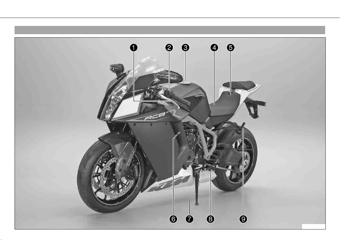
3.1View of vehicle, front left side
100652-10
Page 15

VIEW OF VEHICLE 13
1 Clutch lever
2 Light switch, headlight flasher switch, indicator switch, horn button
3 Filler cap
4 Seat
5 Seat lock
6 Oil dipstick
7 Side stand
8 Shift lever
9 Passenger footrests
Page 16
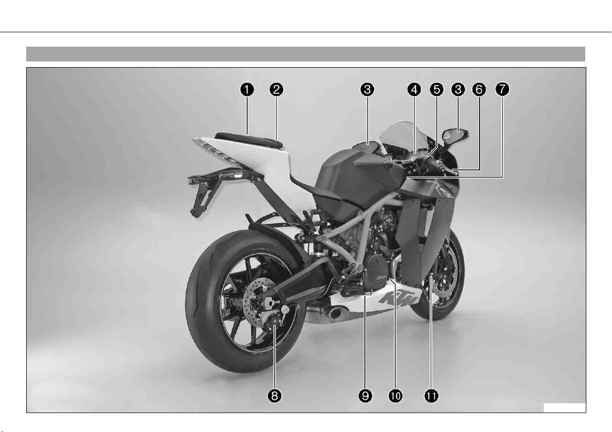
VIEW OF VEHICLE 14
3.2View of vehicle, rear right side
100653-10
Page 17

VIEW OF VEHICLE 15
1 Passenger seat
2 Supporting strap
3 Rear mirror
4 Combination instrument
5 Emergency OFF switch, electric starter button
6 Hand brake lever
7 Chassis number, type label
8 Rear brake caliper
9 Foot brake pedal
10 Engine number
11 Brake calipers, front
Page 18
LOCATION OF SERIAL NUMBERS 16
4.1Vehicle identification number/type label
The vehicle identification number is stamped on the frame behind the steering head on
the right.
The type label is on the frame above the vehicle identification number.
100654-10
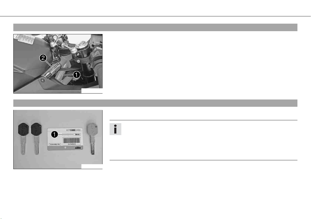
4.2Key number
The key number Code number can be found on the KEYCODECARD.
Info
You need the key number to order a spare key. Keep the KEYCODECARD in a safe
place.
Use the orange programming key to activate and deactivate the black ignition key.
Keep the orange programming key in a safe place: it must only be used for learning
and programming functions.
700222-01
Page 19
LOCATION OF SERIAL NUMBERS 17
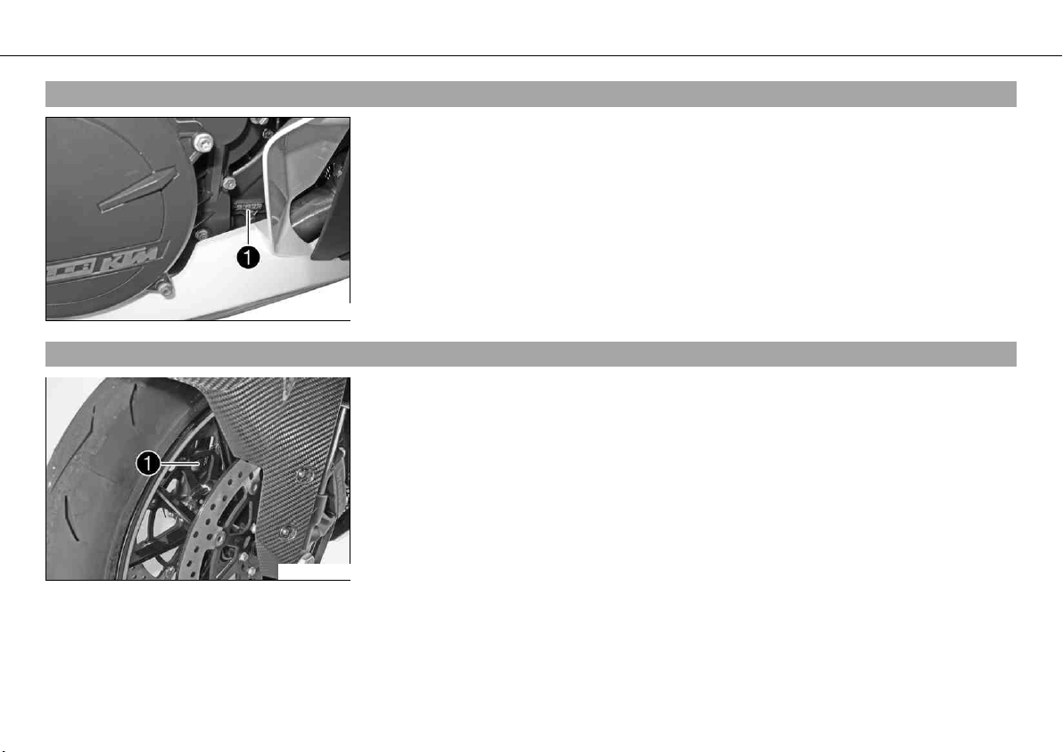
4.3Engine number
The engine number is stamped on the right side of the engine.
100655-10
4.4Fork part number
The fork part number is stamped on the inner side of the fork stub.
100656-10
Page 20
LOCATION OF SERIAL NUMBERS 18
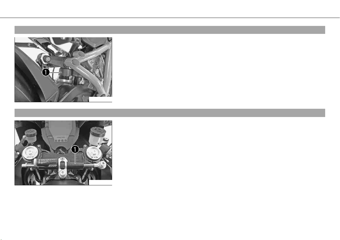
4.5Shock absorber part number
The shock absorber part number is stamped on the upper part of the shock absorber
above the adjusting ring towards the rear.
100657-10
4.6Steering damper part number
The steering damper part number is stamped on the top of the steering damper.
100658-10
Page 21
CONTROLS 19
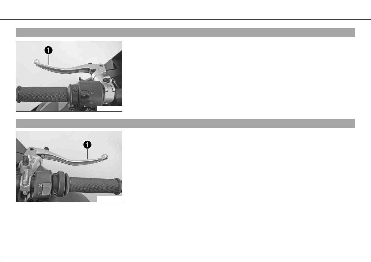
5.1Clutch lever
The clutch lever is fitted on the left side of the handlebar.
The clutch is hydraulic and self-adjusting.
100659-10
5.2Hand brake lever
The hand brake lever is fitted on the right side of the handlebar.
The hand brake lever operates the front brake.
100660-10
Page 22
CONTROLS 20
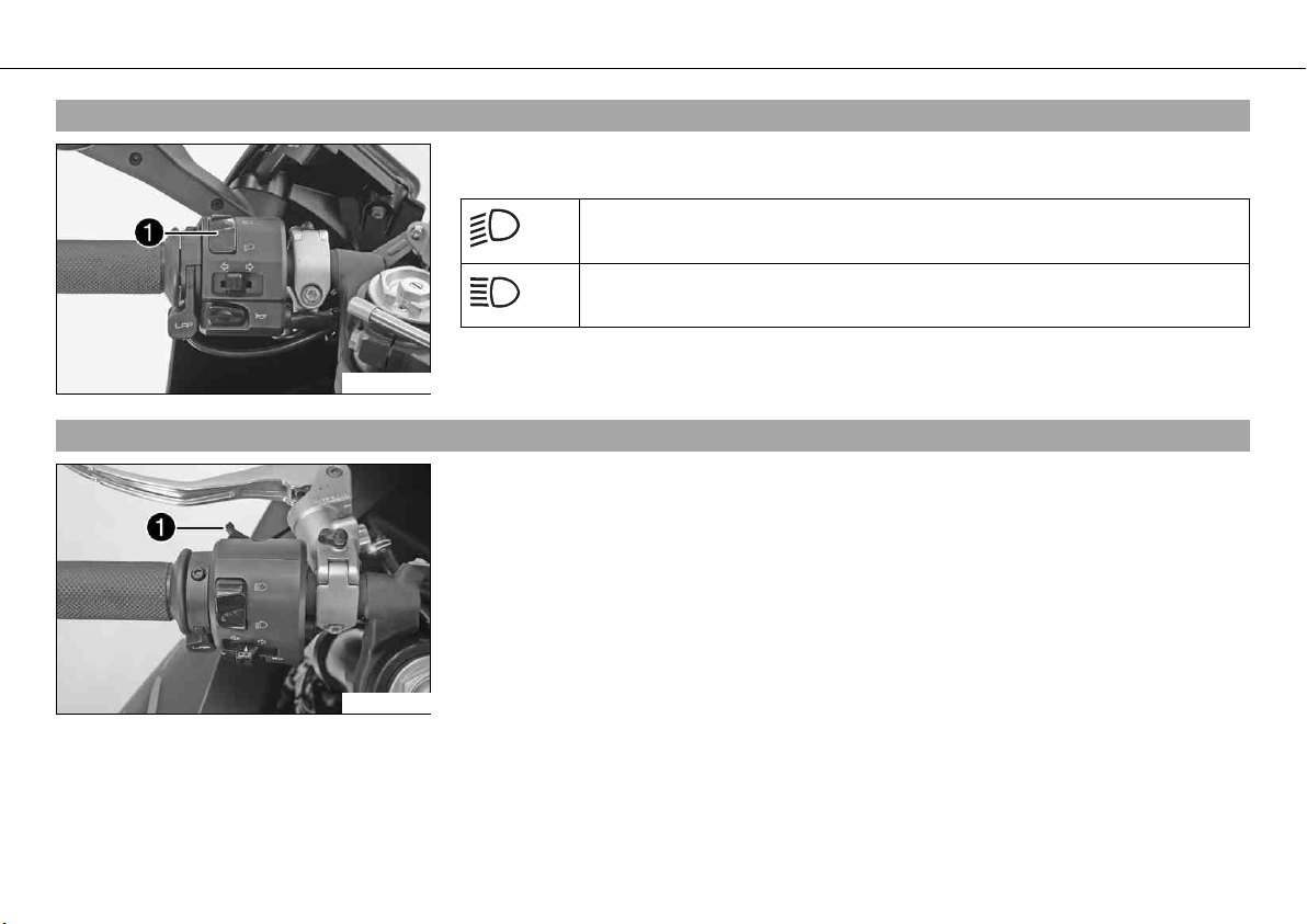
5.3Light switch
The light switch is fitted on the left side of the handlebar.
Possible states
Low beam on – The light switch is in the lower position. In this position,
the low beam and tail light are switched on.
High beam on – The light switch is in the upper position. In this position,
the low beam, the high beam and the tail light are switched on.
100661-10
5.4Headlight flasher switch
The headlight flasher switch is fitted on the left side of the handlebar.
Possible states
• Headlight flasher switch in neutral position
• Headlight flasher switch pressed – The headlight flasher switch (high beam) is operated in this position.
100662-10
Page 23
CONTROLS 21
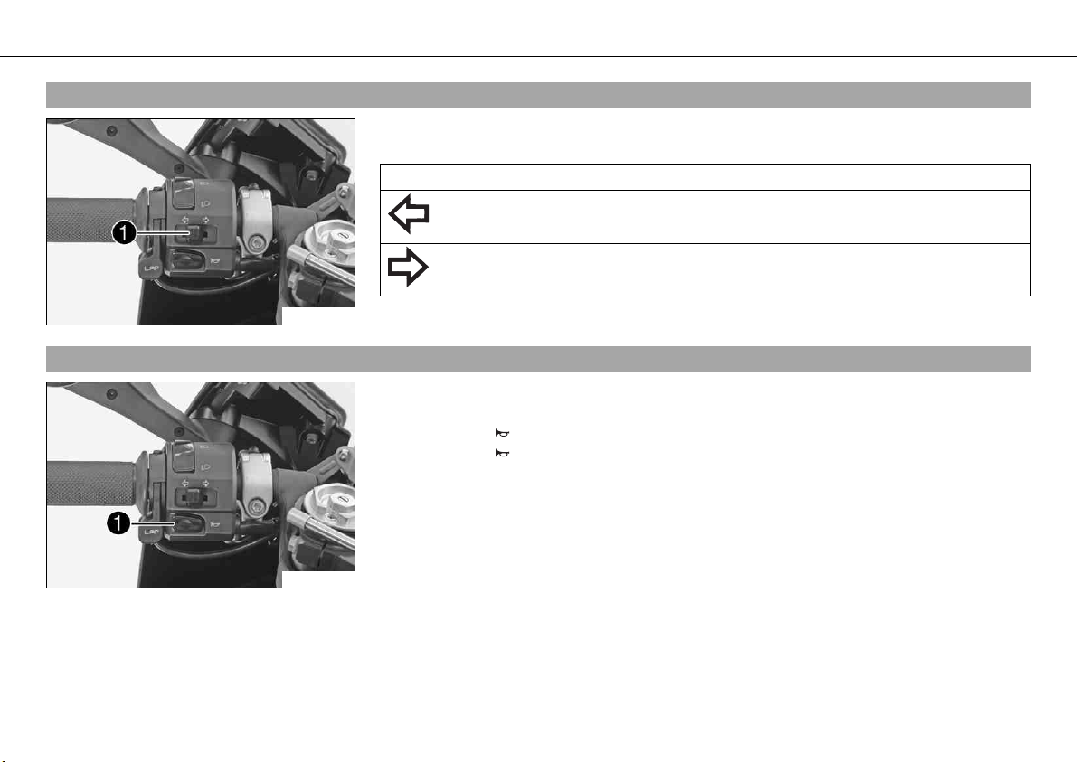
5.5Turn signal switch
The turn signal switch is fitted on the left side of the handlebar.
Possible states
Turn signal off
Left turn signal on – The turn signal switch is pressed to the left. The turn
signal switch automatically returns to the central position after use.
Right turn signal on – The turn signal switch is pressed to the right. The
turn signal switch automatically returns to the central position after use.
5.6Horn button
100661-11
100661-12
To switch off the turn signal, press the turn signal switch towards the switch housing.
The horn button is fitted on the left side of the handlebar.
Possible states
• Horn button in neutral position
• Horn button pressed – The horn is operated in this position.
Page 24
CONTROLS 22
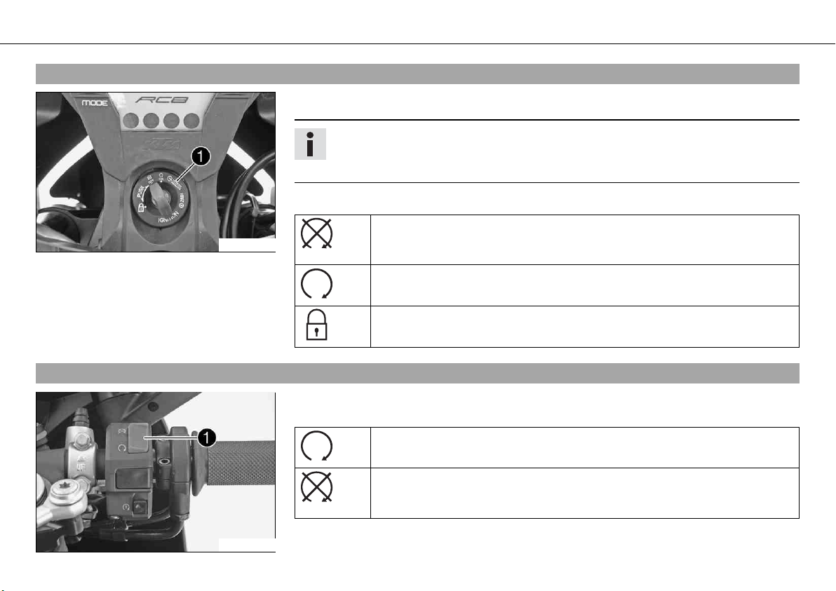
5.7Ignition/steering lock
The ignition/steering lock is located in front of the upper triple clamp.
Info
The ignition may only be switched on using a black ignition key.
Use the orange programming key to activate and deactivate the black ignition key.
Possible states
Ignition off OFF – In this position, the ignition circuit is interrupted, a run-
100663-10
5.8Emergency OFF switch
The emergency OFF switch is installed on the right side of the handlebar.
Possible states
ning engine stops, and a non-running engine will not start. The black ignition key can be removed.
Switch on the ignition ON – In this position, the ignition circuit is closed,
and the engine can be started.
Steering locked – In this position, the ignition circuit is interrupted and the
steering locked. The black ignition key can be removed.
Emergency OFF switch on – This position is necessary for operation; the
ignition circuit is closed.
100664-10
Emergency OFF switch off – In this position, the ignition circuit is
interrupted, a running engine stops, and a non-running engine cannot be
started.
Page 25
CONTROLS 23
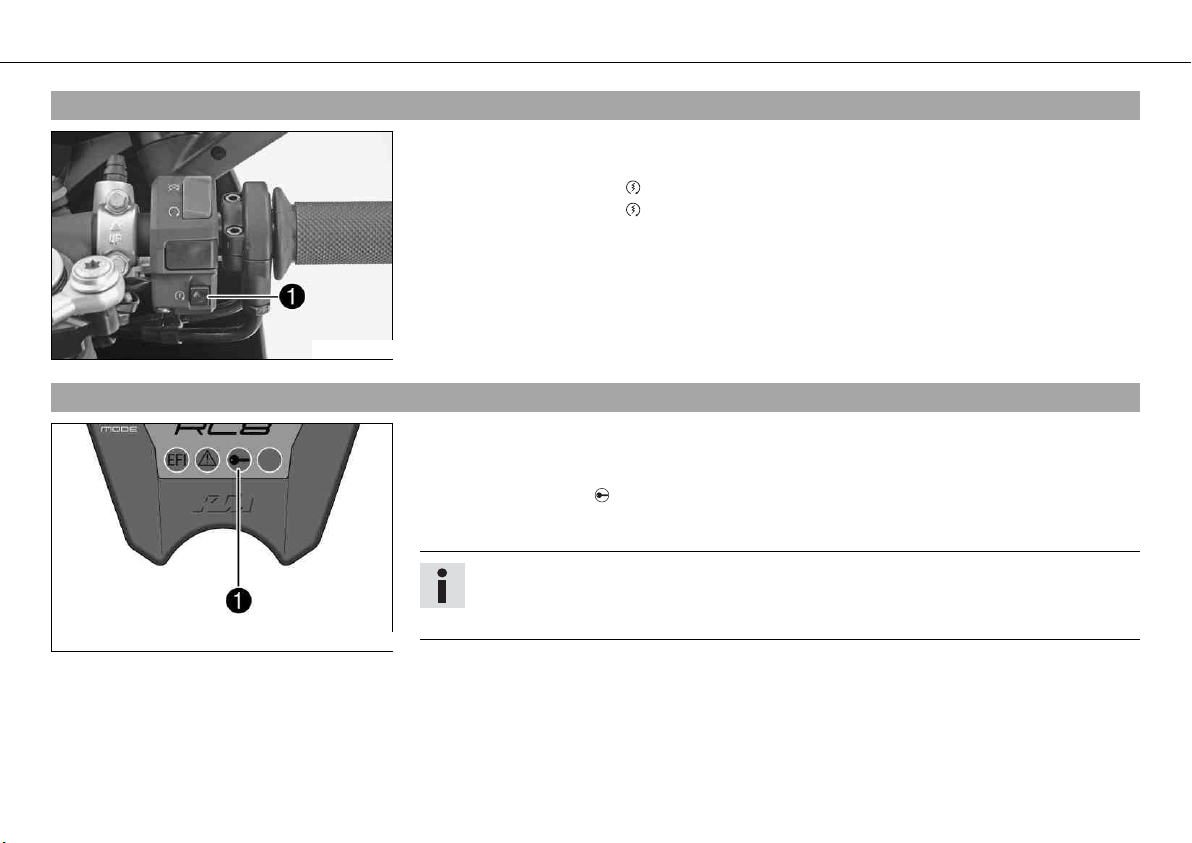
5.9Electric starter button
The electric starter button is fitted on the right side of the handlebar.
Possible states
• Electric starter button in neutral position
• Electric starter button pressed – In this position, the electric starter is operated.
100664-11
5.10immobilizer
The electronic immobilizer secures the vehicle against unauthorized use.
The immobilizer is activated automatically and the engine electronics are locked when the
ignition key is withdrawn.
The red warning lamp flashes at 15 second intervals after one minute.
The red warning lamp can also indicate errors by flashing.
Info
The ignition key contains electronic components. Never attach multiple ignition keys
to a single key ring; this may cause mutual interference and lead to problems.
400679-10
A lost black ignition key must be deactivated to prevent unauthorized persons from operating the vehicle.
The second black ignition key is activated when the vehicle is shipped.
Two additional spare ignition keys (key number on the KEYCODECARD) can be ordered from
an authorized KTM RC8 workshop, but they must be activated before use.
Page 26
CONTROLS 24
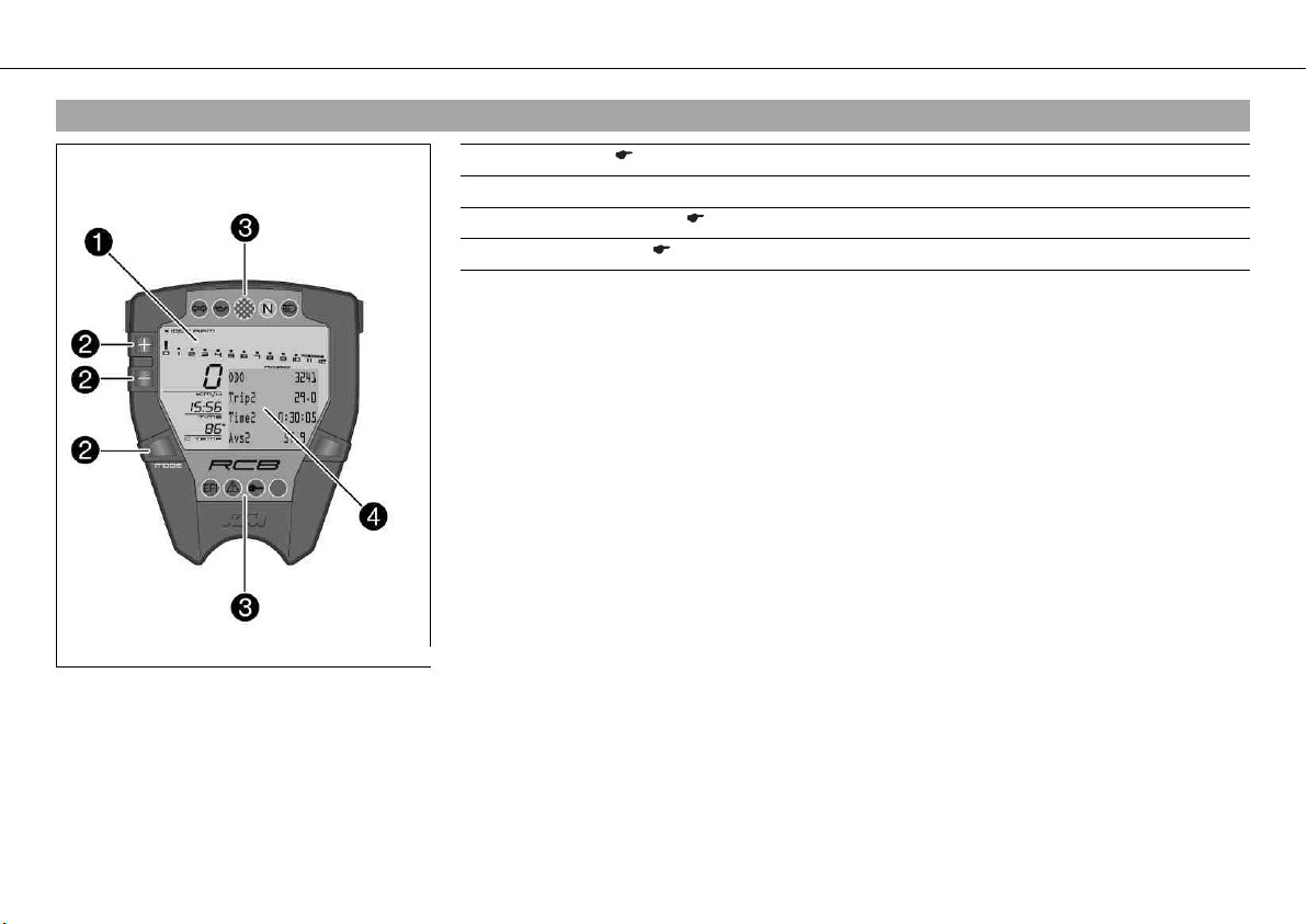
5.11Combination instrument - overview
1 Display ( p. 27)
2 Function buttons
3 Indicator lamps ( p. 29)
4 Info display ( p. 28)
400580-10
Page 27
CONTROLS 25
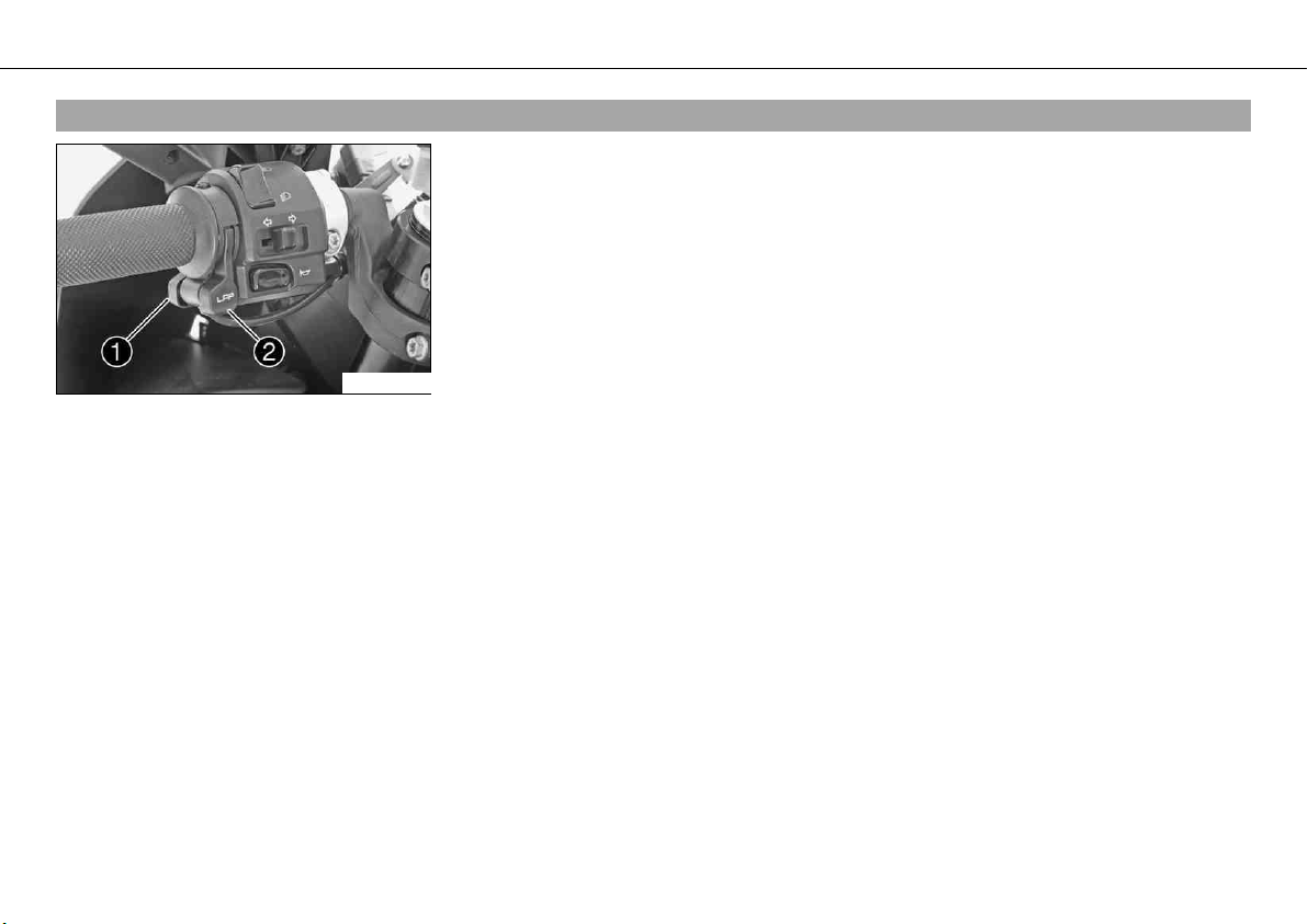
5.12Combination instrument - function buttons on handlebar
The MODE button is fitted on the handlebar, front left.
The LAP button is fitted on the handlebar, rear left.
MODE button
Changes to the next item on the info display in ROAD mode and in RACE mode.
LAP button
Changes to the next item in the info display in ROAD mode. Clocks the lap times in RACE
mode.
100665-10
Page 28
CONTROLS 26
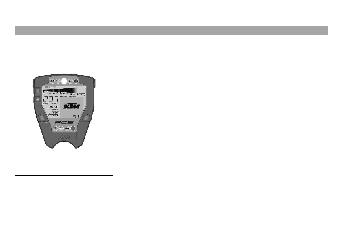
5.13Combination instrument - activation and test
Activation
The combination instrument is activated when the ignition is switched on.
Test
The segments of the tachometer light up in and switch off in sequence.
The speed display counts from 0 to 300 and back.
The remaining display segments outside the info display light up briefly.
The KTM logo appears in the info display.
In ROAD mode, the info display switches to ODO, Trip 1, Time 1, Avs 1 mode.
In RACE mode, the info display switches to LAPSTOGO, LastLap, ±Last, ±Best mode.
400429-10
Page 29
CONTROLS 27
5.14Display
The tachometer displays the engine speed in revolutions per minute (RPM).
The red marking marks the over-rev (excessive speed) range of the engine.
The speed is displayed in kilometers per hour km/h or in miles per hour Mph.
The time appears in segment .
Info
After reconnecting the battery or changing the fuse, the time must be reset.
The coolant temperature is shown in degrees Celsius or Fahrenheit in segment .
The info display shows additional information.
400580-12
Page 30
CONTROLS 28
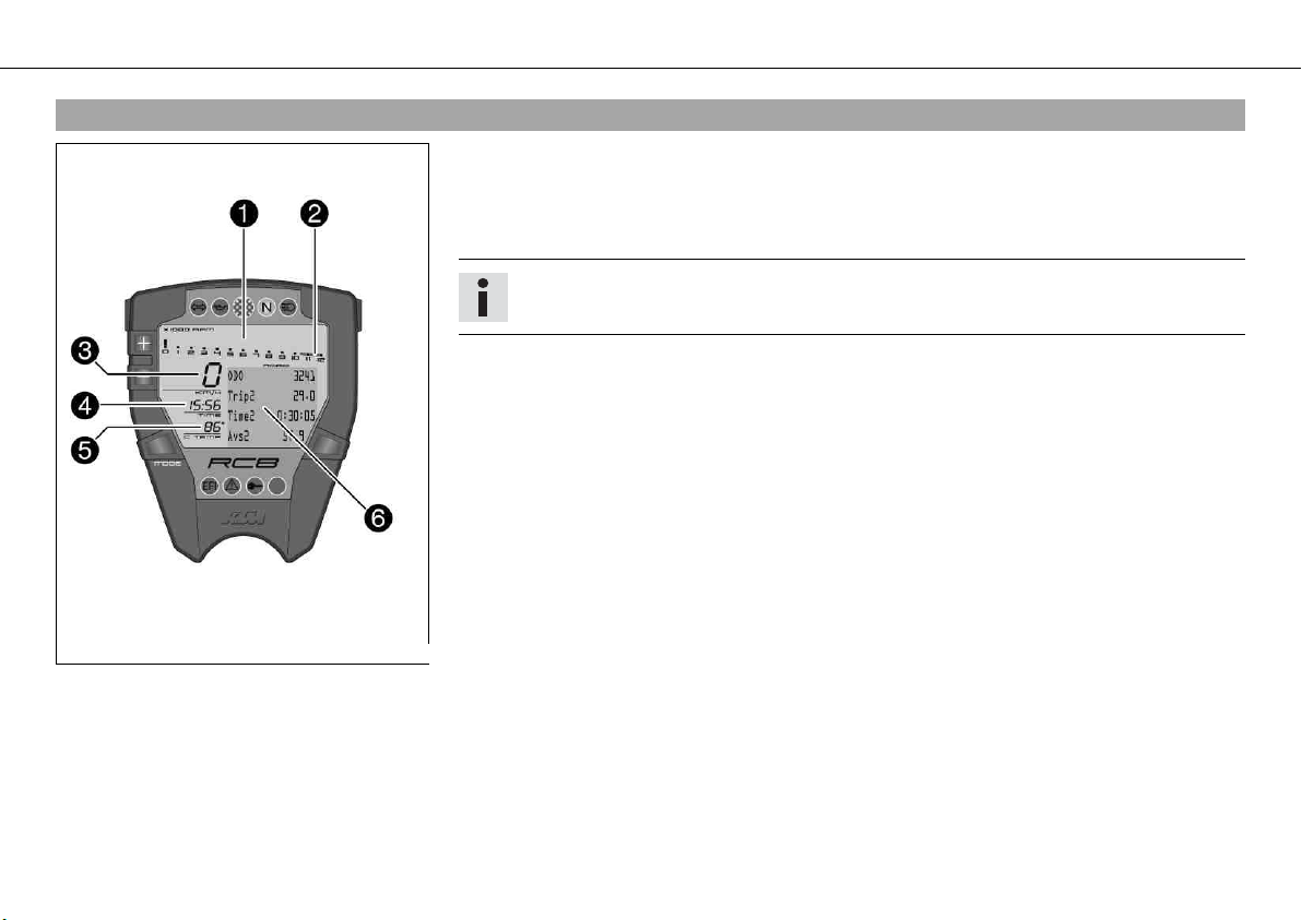
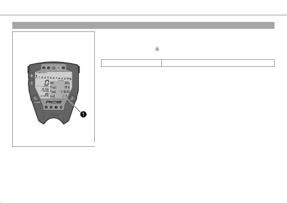
5.15Info display
The info display has two menus.
Menu 1 is ROAD mode (standard) for riding on public roads.
Menu 2 is RACE mode for riding on race tracks. It allows riders to time laps themselves.
If the general warning lamp lights up, the corresponding message is shown periodically
in the info display.
Information repeat 45 s
The information shown in the info display can be controlled with the function buttons.
400580-13
Page 31

CONTROLS 29
5.16Indicator lamps
Possible states
The turn signal indicator lamp flashes green simultaneously with the turn
signal – The turn signal is switched on.
The oil indicator lamp lights up red – The oil pressure is too low.
The shift warning lights up/flashes red – The set shift speed has been
reached.
The idle speed indicator lamp lights up green – The transmission is shifted
to idle.
The high beam indicator lamp lights up blue – The high beam is switched
on.
EFI warning lamp (MIL) lights up / flashes red – The OBD has detected an
emission- or safety-critical fault.
The general warning lights up yellow – An operating safety (warning) message was detected. This is also shown periodocally in the info display.
400580-14
The immobilizer indicator lamp lights up or flashes red – Status or error
message for immobilizer / alarm system.
Page 32

CONTROLS 30
5.17Notes/warnings on the combination instrument
LOW FUEL appears on the info display if the minimum range falls below the specified value.
Distance 20 km (12.4 mi)
400476-01
LOW BATTERY appears on the info display if the battery voltage falls below the specified
value.
Battery voltage 10.80 V
400471-01
Page 33

CONTROLS 31
SERVICE IN xxx KM(MPH) appears on the info display if the distance to the next service falls
below the specified value.
Distance 500 km (310.7 mi)
400472-01
HIGH TEMP appears on the info display if the coolant temperature rises above the specified
value.
Coolant temperature 120 °C (248 °F)
400474-01
FRONT SENSOR appears on the info display if the front cylinder coolant temperature sensor
is faulty.
400469-01
Page 34

CONTROLS 32
REAR SENSOR appears on the info display if the rear cylinder coolant temperature sensor is
faulty.
400470-01
SENSOR ERROR appears on the info display if the discrepancy between the front and rear
cylinder coolant temperature sensor values differs by more than the specified value.
Coolant temperature 10 °C (50 °F)
400468-01
ICE appears on the info display if the external temperature falls below the specified value.
Temperature 3 °C (37 °F)
400467-01
ICE disappears if the external temperature rises above the specified value.
Temperature 4 °C (39 °F)
Page 35

CONTROLS 33
5.18Odometer menu ODO/Trip 1
Condition
• The ignition is on.
• ROAD Mode
– Press the MODE button briefly and repeatedly until ODO appears at the top left of the
info display.
ODO shows the total distance covered.
Trip 1 shows the distance covered since the last reset. For example, between two refueling
stops. Trip 1 is always running and counts up to 9999.9.
400578-01
Time 1 shows the journey time on the basis of Trip 1 and resumes running as soon as a
speed signal is received.
The calculation of this value starts with the first speed signal and ends 3 seconds after the
last speed signal.
Avs 1 (average speed) is coupled with Trip 1 and Time 1.
Press the button . No function
Press the button . No function
Press the button
The display changes to the SET‑UP menu
and the button for
3 - 5 seconds.
Press the MODE but-
The display of Trip 1, Time 1 and Avs 1 is reset
ton for 3 - 5 seconds.
Press the MODE but-
Next display mode
ton briefly.
Page 36

CONTROLS 34
5.19Odometer menu ODO/Trip 2
Condition
• The ignition is on.
• ROAD Mode
– Press the MODE button briefly and repeatedly until ODO appears at the top left of the
info display.
ODO shows the total distance covered.
Trip 2 shows the distance covered since the last reset. For example, between two refueling
stops. Trip 2 is always running and counts up to 9999.9.
400579-01
Time 2 shows the journey time on the basis of Trip 2 and resumes running as soon as a
speed signal is received.
The calculation of this value starts with the first speed signal and ends 3 seconds after the
last speed signal.
Avs 2 (average speed) is coupled with Trip 2 and Time 2.
Press the button . No function
Press the button . No function
Press the button
The display changes to the SET‑UP menu
and the button for
3 - 5 seconds.
Press the MODE but-
The display of Trip 2, Time 2 and Avs 2 is reset
ton for 3 - 5 seconds.
Press the MODE but-
Next display mode
ton briefly.
Page 37

CONTROLS 35
5.20FUELDISTANCE menu
Condition
• The ignition is on.
• ROAD Mode
– Press the MODE button briefly and repeatedly until FUELDISTANCE appears at the top of
the info display.
TripFuel shows the distance covered since the fuel reserve level was reached.
Info
400441-01
This is displayed only after you reach the fuel reserve level.
OuterTemp shows the external temperature.
The external temperature can be switched on and off in the SET‑UP menu.
Press the button . no function
Press the button . no function
Press the button
and the button for
3 - 5 seconds.
Press the MODE button for 3 - 5 seconds.
Press the MODE button briefly.
The display changes to the SET‑UP menu
no function
Next display mode
Page 38

CONTROLS 36
5.21FUELRANGE menu
Condition
• The ignition is on.
• ROAD Mode
– Press the MODE button briefly and repeatedly until FUELRANGE appears at the top of the
info display.
TripFuel shows the distance covered since the fuel reserve level was reached.
Info
400577-01
This is displayed only after you reach the fuel reserve level.
MinRange shows the minimum range you can cover with the fuel reserve.
MaxRange shows the maximum range you can cover with the fuel reserve.
The possible range of the fuel reserve depends on your riding style.
Press the button . No function
Press the button . No function
Press the button
and the button for
3 - 5 seconds.
Press the MODE button for 3 - 5 seconds.
Press the MODE button briefly.
The display changes to the SET‑UP menu
No function
Next display mode
Page 39

CONTROLS 37
5.22DISTANCE TO Next Service menu
Condition
• The ignition is on.
• The motorcycle is upright.
• ROAD Mode
– Press the MODE button briefly and repeatedly until DISTANCE TO Next Service appears in
the info display.
DISTANCE TO Next Service shows the distance before the next service is necessary.
400443-01
Press the button . No function
Press the button . No function
Press the button
The display changes to the SET‑UP menu
and the button for
3 - 5 seconds.
Press the MODE but-
No function
ton for 3 - 5 seconds.
Press the MODE but-
Next display mode
ton briefly.
Page 40

CONTROLS 38
5.23LAPSTOGO menu
Condition
• The ignition is on.
• RACE Mode
– Press the MODE button briefly and repeatedly until LAPSTOGO appears at the top left of
the info display.
LAPSTOGO shows the number of remaining laps.
If an R appears after LAPSTOGO, the stopwatch is running in the background.
If a P appears after LAPSTOGO, the stopwatch in the background is active but waiting for a
400444-01
speed signal. The time is not running.
This function is controlled by the button "LAP".
LastLap shows the lap time of the last lap.
±Last shows the difference between the last lap and the lap before last.
±Best shows the difference between the last lap and the best lap.
If the last lap was the fastest, you see behind ±Best: the Best! symbol in the info display.
Press the button . No function
Press the button . No function
Press the button
The display changes to the SET‑UP menu
and the button for
3 - 5 seconds.
Press the MODE but-
All values in RACE mode are reset (except RACEODO)
ton for 3 - 5 seconds.
Press the MODE but-
Next display mode
ton briefly.
Page 41

CONTROLS 39
5.24TOPSPEED menu
Condition
• The ignition is on.
• RACE Mode
– Press the MODE button briefly and repeatedly until TOPSPEED appears at the top left of
the info display.
If an R appears after TOPSPEED, the stopwatch is running in the background.
If a P appears after TOPSPEED, the stopwatch is not running in the background.
This function is controlled by the button "LAP".
400445-01
TOPSPEED shows the highest lap speed.
LastLap shows the maximum speed of the last lap.
±Last shows the maximum speed difference between the last lap and the lap before.
±Best shows the maximum speed difference between the last lap and the highest maximum
speed.
If the last lap was the lap with the highest maximum speed, the info display shows ±Best:
Best!
Press the button . No function
Press the button . No function
Press the button
The display changes to the SET‑UP menu
and the button for
3 - 5 seconds.
Press the MODE but-
The display of LastLap, ±Last and ±Best are set to 0
ton for 3 - 5 seconds.
Press the MODE but-
Next display mode
ton briefly.
Page 42

CONTROLS 40
5.25LAP/BESTLAP/LastLap menu
Condition
• The ignition is on.
• The motorcycle is upright.
• RACE Mode
– Press the MODE button briefly and repeatedly until LAP/BESTLAP/LastLap appears in the
info display.
LAP shows the selected lap.
BESTLAP shows the number of the lap with the best lap time.
400446-01
LastLap shows the time of the lap behind LAP.
±Lap shows the difference to the lap before.
±Lap shows the difference to the lap after.
Press the button . The next lap is displayed
Press the button . The previous lap is displayed
Press the button
The display changes to the SET‑UP menu
and the button for
3 - 5 seconds.
Press the MODE but-
All values in RACE mode are reset (except RACEODO)
ton for 3 - 5 seconds.
Press the MODE but-
Next display mode
ton briefly.
Page 43

CONTROLS 41
5.26LAP/BESTLAP/TopSpeed menu
Condition
• The ignition is on.
• The motorcycle is upright.
• RACE Mode
– Press the MODE button briefly and repeatedly until LAP/BESTLAP/TopSpeed appears in
the info display.
LAP shows the selected lap.
BESTLAP shows the lap in which the highest maximum speed was reached.
400447-01
TopSpeed shows maximum speed of the lap behind LAP.
±Lap shows the difference to the lap before.
±Lap shows the difference to the lap after.
Press the button . The next lap is displayed
Press the button . The previous lap is displayed
Press the button
The display changes to the SET‑UP menu
and the button for
3 - 5 seconds.
Press the MODE but-
All values in RACE mode are reset (except RACEODO)
ton for 3 - 5 seconds.
Press the MODE but-
Next display mode
ton briefly.
Page 44

CONTROLS 42
5.27Total distance menu in Race mode RACEODO
Condition
• The ignition is on.
• The motorcycle is upright.
• RACE Mode
– Press the MODE button briefly and repeatedly until RACEODO appears at the top of the
info display.
RACEODO shows the total distance covered in RACE mode.
RaceTrip shows the distance covered since the last reset. For example, between two refuel-
400448-01
ing stops. RaceTrip is always running and counts up to 999.9.
MaxRPM shows the highest engine speed reached during the RaceTrip.
TopSpeed shows the highest speed reached during the RaceTrip.
Press the button . No function
Press the button . No function
Press the button
The display changes to the SET‑UP menu
and the button for
3 - 5 seconds.
Press the MODE but-
All values in RACE mode are reset (except RACEODO)
ton for 3 - 5 seconds.
Press the MODE but-
Next display mode
ton briefly.
Page 45

CONTROLS 43
5.28SET‑UP menu
Condition
• The ignition is on.
• The motorcycle is upright.
– Press the button and the button for 3 - 5 seconds.
On the CHANGE MODE menu, you can select between ROAD and RACE mode.
You can set the clock on the SET CLOCK menu.
On the SETTINGS menu, you can set the shift warning light, the lap blank time of the
LAP button, the number of laps, and the reset time of the fuel reserve display.
On the UNITS menu, you can set the units for measuring speed, distance, and temperature.
On the OPTIONS menu, you can switch the tire pressure check and external temperature
display on/off (available as an accessory).
Select EXIT SETUP to close the SET‑UP menu.
The symbol shows which menu you can activate with the button "MODE".
Press the button . The arrow moves up
Press the button . The arrow moves down
400449-01
Press the button
and the button for
3 - 5 seconds.
Press the MODE button for 3 - 5 seconds.
Press the MODE button briefly.
No function
The menu in front of the arrow is selected
The menu in front of the arrow is selected
Page 46

CONTROLS 44
5.29CHANGE MODE menu
Condition
• The ignition is on.
• The motorcycle is upright.
– Press the button and the button for 3 - 5 seconds.
– Press the MODE button briefly.
On the CHANGE MODE menu, you can select between ROAD and RACE mode.
Press the button . Changes the menu
400475-01
Press the button . Changes the menu
Press the button
No function
and the button for
3 - 5 seconds.
Press the MODE but-
Open and exit CHANGE MODE
ton for 3 - 5 seconds.
Press the MODE but-
Open and exit CHANGE MODE
ton briefly.
Page 47

CONTROLS 45
5.30SET CLOCK menu
Condition
• The ignition is on.
• The motorcycle is upright.
– Press the button and the button for 3 - 5 seconds.
– Press the button once until the symbol shows SET CLOCK in the info display.
– Press the MODE button briefly.
You can set the clock on the SET CLOCK menu.
400455-01
Press the button . Increases the value
Press the button . Decreases the value
Press the button
No function
and the button for
3 - 5 seconds.
Press the MODE but-
Open and exit SET CLOCK or change to next value
ton for 3 - 5 seconds.
Press the MODE but-
Open and exit SET CLOCK or change to next value
ton briefly.
Page 48

CONTROLS 46
5.31SETTINGS menu
Condition
• The ignition is on.
• The motorcycle is upright.
– Press the button and the button for 3 - 5 seconds.
– Press the button twice until the symbol shows SETTINGS in the info display.
– Press the MODE button briefly.
On the SHIFT RPMS menu, you can activate the shift warning light.
On the LAP BLANK TIME menu, you can set the lap blank time of the LAP button.
On the SET NUM LAPS menu, you set the number of laps to cover in RACE mode.
On the TRIP F RESET menu, you can set the reaction time of the fuel reserve display to
changes of the fuel level.
Only a KTM-RC8 workshop can make changes on the S.LEARN TPMS menu.
On the BACK… menu, you can switch back to the SET‑UP menu.
The symbol shows which menu you can activate with the button "MODE".
Press the button . The arrow moves up
Press the button . The arrow moves down
400456-01
Press the button
and the button for
3 - 5 seconds.
Press the MODE button for 3 - 5 seconds.
Press the MODE button briefly.
No function
The menu in front of the arrow is selected
The menu in front of the arrow is selected
Page 49

CONTROLS 47
5.32SHIFT RPMS menu
Condition
• The ignition is on.
• The motorcycle is upright.
– Press the button and the button for 3 - 5 seconds.
– Press the button twice until the symbol shows SETTINGS in the info display.
– Press the MODE button briefly.
– Press the MODE button briefly.
400460-01
On the SHIFT RPMS menu, you can activate the shift warning light.
Press the button . Increases the value
Press the button . Decreases the value
Press the button
No function
and the button for
3 - 5 seconds.
Press the MODE but-
Open and exit SHIFT RPMS or change to the next value
ton for 3 - 5 seconds.
Press the MODE but-
Open and exit SHIFT RPMS or change to the next value
ton briefly.
Page 50

CONTROLS 48
5.33LAP menu, LAP BLANK T button
Condition
• The ignition is on.
• The motorcycle is upright.
– Press the button and the button for 3 - 5 seconds.
– Press the button twice until the symbol shows SETTINGS in the info display.
– Press the MODE button briefly.
– Press the button once until the symbol shows LAP BLANK T in the info display.
400461-01
– Press the MODE button briefly.
On the LAP BLANK T menu, you set the lap blank time of the LAP button.
Press the button . Increases the value
Press the button . Decreases the value
Press the button
No function
and the button for
3 - 5 seconds.
Press the MODE but-
Open and exit LAP BLANK T
ton for 3 - 5 seconds.
Press the MODE but-
Open and exit LAP BLANK T
ton briefly.
Page 51

CONTROLS 49
5.34SET NUM LAPS menu
Condition
• The ignition is on.
• The motorcycle is upright.
– Press the button and the button for 3 - 5 seconds.
– Press the button twice until the symbol shows SETTINGS in the info display.
– Press the MODE button briefly.
– Press the button twice until the symbol shows SET NUM LAPS in the info display.
400462-01
– Press the MODE button briefly.
On the SET NUM LAPS menu, you set the number of laps to cover in RACE mode.
Press the button . Increases the value
Press the button . Decreases the value
Press the button
No function
and the button for
3 - 5 seconds.
Press the MODE but-
Open and exit SET NUM LAPS
ton for 3 - 5 seconds.
Press the MODE but-
Open and exit SET NUM LAPS
ton briefly.
Page 52

CONTROLS 50
5.35TRIP F RESET menu
Condition
• The ignition is on.
• The motorcycle is upright.
– Press the button and the button for 3 - 5 seconds.
– Press the button twice until the symbol shows SETTINGS in the info display.
– Press the MODE button briefly.
– Press the button three times until the symbol shows TRIP F RESET in the info dis-
play.
400463-01
– Press the MODE button briefly.
On the TRIP F RESET menu, you can set the reaction time of the fuel reserve display to
changes of the fuel level.
Press the button . Increases the value
Press the button . Decreases the value
Press the button
No function
and the button for
3 - 5 seconds.
Press the MODE but-
Open and exit TRIP F RESET
ton for 3 - 5 seconds.
Press the MODE but-
Open and exit TRIP F RESET
ton briefly.
Page 53

CONTROLS 51
5.36UNITS menu
Condition
• The ignition is on.
• The motorcycle is upright.
– Press the button and the button for 3 - 5 seconds.
– Press the button three times until the symbol shows UNITS in the info display.
– Press the MODE button briefly.
On the SET KM/MILES menu, you can set the units for measuring speed and distance.
On the SET °C/°F menu, you can set the unit for the temperature display.
400458-01
On the BACK… menu, you can switch back to the SET‑UP menu.
The symbol shows which menu you can activate with the button "MODE".
Press the button . The arrow moves up
Press the button . The arrow moves down
Press the button
No function
and the button for
3 - 5 seconds.
Press the MODE but-
The menu in front of the arrow is selected
ton for 3 - 5 seconds.
Press the MODE but-
The menu in front of the arrow is selected
ton briefly.
Page 54

CONTROLS 52
5.37SET KM/MILES menu
Condition
• The ignition is on.
• The motorcycle is upright.
– Press the button and the button for 3 - 5 seconds.
– Press the button three times until the symbol shows UNITS in the info display.
– Press the MODE button briefly.
– Press the MODE button briefly.
400464-01
On the SET KM/MILES menu, you can set the units for measuring speed and distance.
Press the button . Changes the unit
Press the button . Changes the unit
Press the button
No function
and the button for
3 - 5 seconds.
Press the MODE but-
Open and exit SET KM/MILES
ton for 3 - 5 seconds.
Press the MODE but-
Open and exit SET KM/MILES
ton briefly.
Page 55

CONTROLS 53
5.38SET °C/°F menu
Condition
• The ignition is on.
• The motorcycle is upright.
– Press the button and the button for 3 - 5 seconds.
– Press the button three times until the symbol shows UNITS in the info display.
– Press the MODE button briefly.
– Press the button once until the symbol shows SET °C/°F in the info display.
400465-01
– Press the MODE button briefly.
On the SET °C/°F menu, you can set the unit for the temperature display.
Press the button . Changes the unit
Press the button . Changes the unit
Press the button
No function
and the button for
3 - 5 seconds.
Press the MODE but-
Open and exit SET °C/°F
ton for 3 - 5 seconds.
Press the MODE but-
Open and exit SET °C/°F
ton briefly.
Page 56

CONTROLS 54
5.39OPTIONS menu
Condition
• The ignition is on.
• The motorcycle is upright.
– Press the button and the button for 3 - 5 seconds.
– Press the button four times until the symbol shows OPTIONS in the info display.
– Press the MODE button briefly.
On the OPTION TPMS menu, you can switch the tire pressure check on/off (available as an
accessory).
400459-01
On the OPTION OUTTEMP menu, you can switch the external temperature display on/off.
On the BACK… menu, you can switch back to the SET‑UP menu.
The symbol shows which menu you can activate with the button "MODE".
Press the button . The arrow moves up
Press the button . The arrow moves down
Press the button
No function
and the button for
3 - 5 seconds.
Press the MODE but-
The menu in front of the arrow is selected
ton for 3 - 5 seconds.
Press the MODE but-
The menu in front of the arrow is selected
ton briefly.
Page 57

CONTROLS 55
5.40TPMS menu
Condition
• The ignition is on.
• The motorcycle is upright.
– Press the button and the button for 3 - 5 seconds.
– Press the button four times until the symbol shows OPTIONS in the info display.
– Press the MODE button briefly.
– Press the MODE button briefly.
400478-01
On the OPTION TPMS menu, you can switch the tire pressure check on/off (available as an
accessory).
Press the button . Switches the tire pressure display on/off
Press the button . Switches the tire pressure display on/off
Press the button
No function
and the button for
3 - 5 seconds.
Press the MODE but-
Open and exit OPTION TPMS
ton for 3 - 5 seconds.
Press the MODE but-
Open and exit OPTION TPMS
ton briefly.
Page 58

CONTROLS 56
5.41OUTERTEMP menu
Condition
• The ignition is on.
• The motorcycle is upright.
– Press the button and the button for 3 - 5 seconds.
– Press the button four times until the symbol shows OPTIONS in the info display.
– Press the MODE button briefly.
– Press the button once until the symbol shows OPTION OUTTEMP in the info display.
400466-01
– Press the MODE button briefly.
On the OPTION OUTTEMP menu, you can switch the external temperature display on/off.
Press the button . Switches the external temperature display on/off
Press the button . Switches the external temperature display on/off
Press the button
No function
and the button for
3 - 5 seconds.
Press the MODE but-
Open and exit OPTION OUTTEMP
ton for 3 - 5 seconds.
Press the MODE but-
Open and exit OPTION OUTTEMP
ton briefly.
Page 59

CONTROLS 57
Table of functions
Display Press the button . Press the button . Press the button
and the button for
3 - 5 seconds.
Odometer menu
ODO/Trip 1
Odometer menu
ODO/Trip 2
FUELDISTANCE
menu
FUELRANGE menu No function No function The display
DISTANCE TO
Next Service menu
LAPSTOGO menu No function No function The display
TOPSPEED menu No function No function The display
LAP/BESTLAP/LastLap menu
No function No function The display
changes to the
SET‑UP menu
No function No function The display
changes to the
SET‑UP menu
no function no function The display
changes to the
SET‑UP menu
changes to the
SET‑UP menu
No function No function The display
changes to the
SET‑UP menu
changes to the
SET‑UP menu
changes to the
SET‑UP menu
The next lap is displayed
The previous lap is
displayed
The display
changes to the
SET‑UP menu
Press the MODE button for 3 - 5 seconds.
The display of
Trip 1, Time 1 and
Avs 1 is reset
The display of
Trip 2, Time 2 and
Avs 2 is reset
no function Next display mode
No function Next display mode
No function Next display mode
All values in
RACE mode are
reset (except
RACEODO)
The display of Last-
Lap, ±Last and
±Best are set to 0
All values in
RACE mode are
reset (except
RACEODO)
Press the MODE button
briefly.
Next display mode
Next display mode
Next display mode
Next display mode
Next display mode
Page 60

CONTROLS 58
Table of functions
Display Press the button . Press the button . Press the button
and the button for
3 - 5 seconds.
LAP/BESTLAP/TopSpeed menu
Total distance
menu in Race mode
RACEODO
SET‑UP menu The arrow moves up The arrow moves
CHANGE MODE
menu
SET CLOCK menu Increases the value Decreases the value No function Open and
SETTINGS menu The arrow moves up The arrow moves
SHIFT RPMS menu Increases the value Decreases the value No function Open and exit
LAP menu,
LAP BLANK T button
The next lap is displayed
No function No function The display
Changes the menu Changes the menu No function Open and exit
Increases the value Decreases the value No function Open and
The previous lap is
displayed
down
down
The display
changes to the
SET‑UP menu
changes to the
SET‑UP menu
No function The menu in front
No function The menu in front
Press the MODE button for 3 - 5 seconds.
All values in
RACE mode are
reset (except
RACEODO)
All values in
RACE mode are
reset (except
RACEODO)
of the arrow is
selected
CHANGE MODE
exit SET CLOCK or
change to next
value
of the arrow is
selected
SHIFT RPMS or
change to the next
value
exit LAP BLANK T
Press the MODE button
briefly.
Next display mode
Next display mode
The menu in front of the
arrow is selected
Open and exit
CHANGE MODE
Open and exit SET CLOCK
or change to next value
The menu in front of the
arrow is selected
Open and exit
SHIFT RPMS or change to
the next value
Open and
exit LAP BLANK T
Page 61

CONTROLS 59
Table of functions
Display Press the button . Press the button . Press the button
and the button for
3 - 5 seconds.
SET NUM LAPS
menu
TRIP F RESET menu Increases the value Decreases the value No function Open and exit
UNITS menu The arrow moves up The arrow moves
SET KM/MILES
menu
SET °C/°F menu Changes the unit Changes the unit No function Open and
OPTIONS menu The arrow moves up The arrow moves
TPMS menu Switches the tire
OUTERTEMP menu Switches the exter-
Increases the value Decreases the value No function Open and exit
No function The menu in front
down
Changes the unit Changes the unit No function Open and exit
No function The menu in front
down
pressure display
on/off
nal temperature
display on/off
Switches the tire
pressure display
on/off
Switches the external temperature
display on/off
No function Open and
No function Open and exit
Press the MODE button for 3 - 5 seconds.
SET NUM LAPS
TRIP F RESET
of the arrow is
selected
SET KM/MILES
exit SET °C/°F
of the arrow is
selected
exit OPTION TPMS
OPTION OUTTEMP
Press the MODE button
briefly.
Open and exit
SET NUM LAPS
Open and exit
TRIP F RESET
The menu in front of the
arrow is selected
Open and exit
SET KM/MILES
Open and exit SET °C/°F
The menu in front of the
arrow is selected
Open and
exit OPTION TPMS
Open and exit OPTION
OUTTEMP
Page 62

CONTROLS 60
Table of conditions and activability
Display
• The ignition is on.
• The ignition is on.
• The ignition is on.
• The ignition is on.
• The ignition is on.
Menu can be
activated
• ROAD Mode
Odometer menu ODO/Trip 1 •
Odometer menu ODO/Trip 2 •
FUELDISTANCE menu •
FUELRANGE menu •
DISTANCE TO Next Service menu •
LAPSTOGO menu •
TOPSPEED menu •
LAP/BESTLAP/LastLap menu •
LAP/BESTLAP/TopSpeed menu •
Total distance menu in
Race mode RACEODO
SET‑UP menu •
CHANGE MODE menu • •
SET CLOCK menu •
SETTINGS menu •
SHIFT RPMS menu •
LAP menu, LAP BLANK T button •
SET NUM LAPS menu •
• The motorcycle is
upright.
• ROAD Mode
• RACE Mode
• The motorcycle is
upright.
• RACE Mode
•
• The motorcycle is
upright.
Page 63

CONTROLS 61
Table of conditions and activability
Display
• The ignition is on.
• The ignition is on.
• The ignition is on.
• The ignition is on.
• The ignition is on.
Menu can be
activated
• ROAD Mode
TRIP F RESET menu •
UNITS menu •
SET KM/MILES menu •
SET °C/°F menu •
OPTIONS menu •
TPMS menu • •
OUTERTEMP menu • •
5.42Displaying lap times
• The motorcycle is
upright.
• ROAD Mode
Condition
The ignition is on.
The motorcycle is upright.
RACE Mode
• RACE Mode
• The motorcycle is
upright.
• RACE Mode
• The motorcycle is
upright.
Page 64

CONTROLS 62
– Press the MODE button briefly and repeatedly until LAP/BESTLAP/LastLap appears in the
info display.
LAP01 appears on the left of the info display.
– Press the button .
The next lap is displayed.
– Press the button .
The previous lap is displayed.
400446-01
5.43Displaying maximum speed
400447-01
– Press the MODE button briefly.
Next display mode
Condition
The ignition is on.
The motorcycle is upright.
RACE Mode
– Press the MODE button briefly and repeatedly until LAP/BESTLAP/TopSpeed appears in
the info display.
LAP01 appears on the left of the info display.
– Press the button .
The next lap is displayed.
– Press the button .
The previous lap is displayed.
– Press the MODE button briefly.
Next display mode
Page 65

CONTROLS 63
5.44Setting ROAD or RACE mode
Condition
The ignition is on.
The motorcycle is upright.
– Press the button and the button for 3 - 5 seconds.
– Press the MODE button briefly.
The mode set is shown in the info display.
– Select ROAD mode or RACE mode with the button or the button.
– Press the MODE button briefly.
The settings are stored and the display changes to the SET‑UP menu.
– Press the button briefly and repeatedly until the symbol shows EXIT SETUP in the
400475-01
5.45Setting the clock with SET CLOCK
400455-01
info display.
– Press the MODE button briefly.
Condition
The ignition is on.
The motorcycle is upright.
– Press the button and the button for 3 - 5 seconds.
– Press the button once until the symbol shows SET CLOCK in the info display.
– Press the MODE button briefly.
The hour is shown.
– Set the hour with the button or the button.
– Press the MODE button briefly.
The minutes are shown.
– Set the minutes with the button or the button.
Page 66

CONTROLS 64
– Press the MODE button briefly.
The settings are stored and the display changes to the SET‑UP menu.
– Press the button briefly and repeatedly until the symbol shows EXIT SETUP in the
info display.
– Press the MODE button briefly.
5.46Adjusting shift speed RPM1/2
Condition
The ignition is on.
The motorcycle is upright.
– Press the button and the button for 3 - 5 seconds.
– Press the button twice until the symbol shows SETTINGS in the info display.
– Press the MODE button briefly.
– Press the MODE button briefly.
RPM1and RPM2 appear on the info display.
The engine speed after RPM1 flashes.
Info
400460-01
– Set the engine speed with the button or the button .
– Press the MODE button briefly.
The engine speed can be set at intervals of 50.
RPM1 is the engine speed above which the shift warning light starts to flash.
The engine speed after RPM2 flashes.
Page 67

CONTROLS 65
Info
RPM2 is the engine speed above which the shift warning light lights up con-
stantly. If RPM1 = RPM2, the shift warning light lights up constantly when you
reach the engine speed set.
– Set the engine speed with the button or the button .
– Press the MODE button briefly.
The settings are stored and the display changes to the SETTING menu.
Info
At delivery, RPM1 is set to 10000 and RPM2 to 10500.
– Press the button briefly and repeatedly until the symbol shows BACK... in the info
display.
– Press the MODE button briefly.
– Press the button briefly and repeatedly until the symbol shows EXIT SETUP in the
info display.
– Press the MODE button briefly.
5.47Setting the blank time of the LAP button LAP BLANK T
Condition
The ignition is on.
The motorcycle is upright.
Page 68

CONTROLS 66
– Press the button and the button for 3 - 5 seconds.
– Press the button twice until the symbol shows SETTINGS in the info display.
– Press the MODE button briefly.
– Press the button once until the symbol shows LAP BLANK T in the info display.
– Press the MODE button briefly.
LAP BLANK T. appears in the info display.
Info
400461-01
– Set the blank time of the LAP button with the button or the button.
– Press the MODE button briefly.
– Press the button briefly and repeatedly until the symbol shows BACK... in the info
– Press the MODE button briefly.
– Press the button briefly and repeatedly until the symbol shows EXIT SETUP in the
– Press the MODE button briefly.
At delivery, LAP BLANK T. is set to 1 second.
Tip
With LAP BLANK T., you can prevent the lap from being timed too short. This may
happen if you accidentally press the LAP button twice in a row.
Info
LAP BLANK T. can be set between 1 and 200.
The settings are stored and the display changes to the SETTINGS menu.
display.
info display.
Page 69

CONTROLS 67
5.48Setting the number of laps SET NUM LAPS
Condition
The ignition is on.
The motorcycle is upright.
– Press the button and the button for 3 - 5 seconds.
– Press the button twice until the symbol shows SETTINGS in the info display.
– Press the MODE button briefly.
– Press the button twice until the symbol shows SET NUM LAPS in the info display.
– Press the MODE button briefly.
TOTAL LAPS appears in the info display with the number of laps.
Info
400462-01
– Set the number of laps with the button or the button.
– Press the MODE button briefly.
– Press the button briefly and repeatedly until the symbol shows BACK... in the info
– Press the MODE button briefly.
– Press the button briefly and repeatedly until the symbol shows EXIT SETUP in the
– Press the MODE button briefly.
When delivered, the number of TOTAL LAPS is set to 99 laps.
Info
You can set TOTAL LAPS to between 1 and 99 laps.
The settings are stored and the display changes to the SETTINGS menu.
display.
info display.
Page 70

CONTROLS 68
5.49Setting the fuel reserve display TRIPF RESET
Condition
The ignition is on.
The motorcycle is upright.
– Press the button and the button for 3 - 5 seconds.
– Press the button twice until the symbol shows SETTINGS in the info display.
– Press the MODE button briefly.
– Press the button three times until the symbol shows TRIP F RESET in the info dis-
play.
– Press the MODE button briefly.
TRIPF RESET appears in the info display with the reaction time.
400463-01
Info
At delivery, TRIPF RESET is set to 300 seconds.
– Set the reaction time of the fuel reserve display with the button or the button.
Info
You can set the TRIPF RESET to between 10 and 1000 seconds in steps of 10.
– Press the MODE button briefly.
The settings are stored and the display changes to the SETTINGS menu.
– Press the button briefly and repeatedly until the symbol shows BACK... in the info
display.
– Press the MODE button briefly.
– Press the button briefly and repeatedly until the symbol shows EXIT SETUP in the
info display.
– Press the MODE button briefly.
Page 71

CONTROLS 69
5.50Setting the kilometers/miles SET KM/MILES
Info
Making a country-specific setting.
Condition
The ignition is on.
The motorcycle is upright.
– Press the button and the button for 3 - 5 seconds.
– Press the button three times until the symbol shows UNITS in the info display.
– Press the MODE button briefly.
– Press the MODE button briefly.
The selected unit appears on the left of the display.
– Select the unit with the button or the button.
– Press the MODE button briefly.
400464-01
– Press the button briefly and repeatedly until the symbol shows BACK... in the info
– Press the MODE button briefly.
– Press the button briefly and repeatedly until the symbol shows EXIT SETUP in the
– Press the MODE button briefly.
The settings are stored and the display changes to the UNITS menu.
display.
info display.
Page 72

CONTROLS 70
5.51Setting the temperature unit SET °C/°F
Condition
The ignition is on.
The motorcycle is upright.
– Press the button and the button for 3 - 5 seconds.
– Press the button three times until the symbol shows UNITS in the info display.
– Press the MODE button briefly.
– Press the button once until the symbol shows SET °C/°F in the info display.
– Press the MODE button briefly.
The selected unit appears on the left of the display.
– Select the unit with the button or the button.
400465-01
– Press the MODE button briefly.
The settings are stored and the display changes to the UNITS menu.
– Press the button briefly and repeatedly until the symbol shows BACK... in the info
display.
– Press the MODE button briefly.
– Press the button briefly and repeatedly until the symbol shows EXIT SETUP in the
info display.
– Press the MODE button briefly.
5.52Switching the external temperature display on/off
Condition
The ignition is on.
The motorcycle is upright.
Page 73

CONTROLS 71
– Press the button and the button for 3 - 5 seconds.
– Press the button four times until the symbol shows OPTIONS in the info display.
– Press the MODE button briefly.
– Press the button once until the symbol shows OPTION OUTTEMP in the info display.
– Press the MODE button briefly.
You see ENABLED or DISABLED in the info display.
– You can switch the external temperature display on/off with the button or the but-
ton.
400466-01
– Press the MODE button briefly.
The settings are stored and the display changes to the OPTIONS menu.
– Press the button briefly and repeatedly until the symbol shows BACK... in the info
display.
– Press the MODE button briefly.
– Press the button briefly and repeatedly until the symbol shows EXIT SETUP in the
info display.
– Press the MODE button briefly.
Page 74

CONTROLS 72
5.53Opening the filler cap
– Lift the cover of the filler cap and insert the ignition key in the lock.
– Turn the ignition key clockwise until the filler cap opens.
– Open the filler cap.
100666-10
Page 75

CONTROLS 73
5.54Closing the filler cap
Warning
Fire hazard Fuel is highly flammable, poisonous and harmful to your health.
– When closing the filler cap, ensure that it is closed correctly. Change cloth-
ing that came into contact with fuel. Immediately clean skin that came into
contact with fuel using soap and water.
– Close the filler cap. Push down the filler cap slightly until the lock closes.
– Remove the ignition key and close the cover.
100667-10
5.55Supporting strap
The supporting strap is provided for the passenger to hold on to.
100668-10
Page 76

CONTROLS 74
5.56Seat lock
The seat lock is behind the seat.
It can be locked with the ignition key.
100669-10
5.57Tool set
The tool set is in the storage compartment under the seat.
100670-10
Page 77

CONTROLS 75
5.58Helmet lock
The steel cable in the tool set can be used to lock a helmet to the vehicle to prevent it from
being stolen.
Warning
Danger of accidents Impairment of ride behavior and vehicle operation if a helmet
or helmet lock is attached to the vehicle.
– Do not use the helmet lock for holding a helmet or other objects during the jour-
ney. Always remove the helmet lock before starting out.
100671-01
5.59Passenger footrests
The passenger footrests can be folded up and down.
Possible states
• Passenger footrests folded up – For operation without a passenger.
• Passenger footrests folded down – For operation with a passenger.
100672-01
Page 78

CONTROLS 76
5.60Shift lever
The shift lever is mounted on the left of the engine.
100673-10
The gear positions can be seen in the picture.
The neutral or idle position is between the first and second gear.
100674-10
Page 79

CONTROLS 77
5.61Foot brake pedal
The foot brake pedal is in front of the right footrest.
The foot brake pedal operates the rear brake.
100675-10
5.62Side stand
The side stand is coupled with the safety start system; see the riding instructions.
Possible states
• Side stand folded out – The vehicle can be leaned on the side stand. The safety start
system is active.
• Side stand folded in – This position is mandatory for all journeys. The safety start system is inactive.
100676-10
Page 80

GENERAL TIPS AND HINTS ON PUTTING INTO OPERATION 78
6.1advice on first use
Danger
Danger of accidents Danger arising from the rider's judgement being impaired.
– Do not use the vehicle if you are inexperienced or if you have consumed alcohol or drugs.
Warning
Risk of injury Missing or insufficient protective clothing increases the risk of injury.
– Wear protective clothing (helmet, boots, gloves, pants and jacket with protectors) every time you ride the vehicle. Always wear
protective clothing, which must be in perfect condition and meet legal requirements.
Warning
Danger of crashing Impairment of ride behavior due to different tire tread patterns on front and rear wheels.
– The front and rear wheels must be fitted with tires with similar tread patterns to prevent loss of control over the vehicle.
Warning
Danger of accidents Uncontrollable handling characteristics due to non-approved and/or non-recommended tires/wheels.
– Only tires/wheels approved by KTM and with the corresponding speed index should be used.
Warning
Danger of accidents Reduced road grip with new tires.
– New tires have a smooth rolling surface and therefore cannot provide full road grip. The entire rolling surface must be rough-
ened in the first 200 kilometers (124.3 miles) by moderate riding at alternating angles. The full grip levels are not achieved
until the tires have been run in.
Warning
Danger of accidents Brake system failure.
– If the foot brake pedal is not released, the brake linings drag permanently. The rear brake can fail due to overheating. Take your
foot off the foot brake pedal if you do not want to brake.
Page 81

GENERAL TIPS AND HINTS ON PUTTING INTO OPERATION 79
Info
When using your vehicle, remember that others may feel disturbed by excessive noise.
– Make sure that the pre-delivery inspection work has been carried out exclusively by an authorized KTM-RC8 workshop.
You receive a delivery certificate and the service record at vehicle handover.
– Before your first trip, read the entire operating instructions carefully.
– Get to know the controls.
– Adjust the basic position of clutch lever. ( p. 176)
– Adjust the basic position of the handbrake lever. ( p. 130)
– Adjust the footbrake pedal. ( p. 121)
– Get used to handling the vehicle on an empty car park before making a longer trip. Try also to ride as slowly as possible to get a better
feeling for the motorcycle.
– Hold the handlebars firmly with both hands and keep your feet on the footrests when riding.
– Run the engine in. ( p. 79)
6.2Running the engine in
– Do not exceed the specified engine speed and load during the running-in period.
Guideline
Maximum engine speed
During the first: 1,000 km (621.4 mi) 7,500 rpm
After the first: 1,000 km (621.4 mi) 10,500 rpm
– Avoid full-throttle operation!
Page 82

GENERAL TIPS AND HINTS ON PUTTING INTO OPERATION 80
6.3Loading the vehicle
Warning
Danger of accidents Unstable riding behavior.
– Do not exceed the maximum permitted weight and axle loads. The overall weight consists of: motorcycle operational and with a
full tank, driver and passenger with protective clothing and helmet, baggage.
Warning
Danger of accidents Unstable handling characteristics due to incorrect mounting of suitcase and/or tank rucksack.
– Mount and secure suitcase and tank rucksack according to the manufacturer's instructions.
Warning
Danger of accidents Unstable handling characteristics at high speed.
– Adapt your speed according to your payload. If the motorcycle is loaded with luggage, ride more slowly.
Maximum speed with luggage 130 km/h (80.8 mph)
Warning
Danger of accidents Destruction of luggage carrier system.
– If the motorcycle is fitted with luggage cases, note the manufacturer's specifications concerning the maximum payload.
Warning
Danger of accidents Poor visibility for other road users due to slipped baggage.
– If the tail light is covered, you are less visible to traffic behind you, especially in the dark. Check that your baggage is fixed
properly at regular intervals.
Warning
Danger of accidents Changed handling characteristics and longer stopping distance with excessive payload.
– Adapt your speed according to your payload.
Page 83

GENERAL TIPS AND HINTS ON PUTTING INTO OPERATION 81
Warning
Danger of accidents Unstable handling characteristics due to slipped baggage.
– Check the way your baggage is fixed regularly.
– If you carry any baggage, make sure it is fixed firmly as close as possible to the center of the vehicle and ensure even weight distribu-
tion between the front and rear wheels.
– Do not exceed the overall maximum permitted weight and the axle loads.
Guideline
Maximum permissible total weight 380 kg (838 lb.)
Maximum permissible front axle load 150 kg (331 lb.)
Maximum permissible rear axle load 240 kg (529 lb.)
Page 84

RIDING INSTRUCTIONS 82
7.1Checks to be made before putting into operation
Info
During operation, the motorcycle must be in a technically perfect condition.
In the interest of riding safety, you should get into the habit of making a general check of the motorcycle before every journey.
– Check the engine oil level. ( p. 187)
– Check the engine for oil leaks.
– Check the fuel level.
– Bleed fork legs. ( p. 101)
Guideline
Every 1,000 km (621.4 mi)
– Check the chain tension. ( p. 123)
– Clean the chain. ( p. 122)
– Check the tire condition. ( p. 145)
– Check the tire pressure. ( p. 147)
– Check the front brake fluid level. ( p. 131)
– Check the rear brake fluid level. ( p. 134)
– Check the front brake linings. ( p. 133)
– Check the rear brake linings. ( p. 136)
– Check the brake system.
– Check the coolant level. ( p. 173)
– Check the adjustment and smooth operation of all operating elements.
– Check the functioning of the electrical equipment.
– Check that any luggage is fastened correctly.
Page 85

RIDING INSTRUCTIONS 83
– Sit on the motorcycle and check the setting of the rear mirror.
7.2Starting
Danger
Danger of poisoning Exhaust gases are poisonous and can result in unconsciousness and/or death.
– When running the engine, always make sure there is sufficient ventilation, and do not start or run the engine in a closed space
without an effective exhaust extraction system.
Caution
Danger of accidents If the vehicle is operated with a discharged battery or without a battery, electronic components and safety
equipment may be damaged.
– Never operate the vehicle with a discharged battery or without a battery.
Note
Engine failure High engine speeds in cold engines have a negative effect on the service life of the engine.
– Always warm up the engine at low engine speeds.
Page 86

RIDING INSTRUCTIONS 84
– Press the emergency OFF switch into the position .
– Switch off the ignition by turning the black programming key to the position ON .
After you switch on the ignition, you can hear the fuel pump working for about two
seconds. The function test of the combination instrument is run at the same time.
– Shift into neutral.
The green idling speed indicator lamp N lights up.
– Press the electric starter button .
Info
Do not press the electric starter button until the function test of the combination
instrument is finished.
When starting, DO NOT open the throttle. If you apply the throttle during the
starting procedure, the engine management shuts off the injectors, therefore the
engine will not start.
Press the starter for a maximum of 5 seconds. Wait for a least 5 seconds before
trying again.
This motorcycle is equipped with a safety start system. You can only start the
engine if the transmission is in neutral or if the clutch is pulled when a gear is
engaged. If the side stand is folded down and you shift into gear and release the
100677-10
– Take the weight off the side stand and swing it upwards with your foot as far as it will
clutch, the engine stops.
go.
7.3Starting up
– Pull the clutch lever, shift into first gear, release the clutch slowly and at the same time open the throttle.
Page 87

RIDING INSTRUCTIONS 85
7.4Shifting, riding
Warning
Danger of accidents Abrupt load alterations can cause the vehicle to get out of control.
– Avoid abrupt load alterations and sudden braking actions, and adapt your speed to the road conditions.
Warning
Danger of accidents If you shift down at high engine speed, the rear wheel can lock up.
– Do not shift into a low gear at high engine speed. The engine races and the rear wheel can lock up.
Warning
Danger of accidents Malfunctions caused by incorrect ignition key position.
– Do not change the ignition key position during a journey.
Warning
Danger of accidents Distraction from traffic activity by adjustments to the vehicle.
– Make all adjustments when the vehicle is at a standstill.
Warning
Risk of injury The passenger must be able to sit securely on the passenger seat.
– The passenger must hold on to the rider or supporting strap firmly and place his/her feet on the passenger footrests. Observe
the regulations concerning the minimum age for passengers in your country.
Warning
Danger of accidents Danger of accidents caused by dangerous driving.
– Observe the traffic regulations and ride defensively and with foresight in order to recognize danger as early as possible.
Page 88

RIDING INSTRUCTIONS 86
Warning
Danger of accidents Reduced road grip with cold tires.
– On every journey, take the first miles carefully at moderate speed until the tires reach operating temperature and optimal road
grip is ensured.
Warning
Danger of accidents Reduced road grip with new tires.
– New tires have a smooth rolling surface and therefore cannot provide full road grip. The entire rolling surface must be rough-
ened in the first 200 kilometers (124.3 miles) by moderate riding at alternating angles. The full grip levels are not achieved
until the tires have been run in.
Warning
Danger of accidents Unstable riding behavior.
– Do not exceed the maximum permitted weight and axle loads. The overall weight consists of: motorcycle operational and with a
full tank, driver and passenger with protective clothing and helmet, baggage.
Warning
Danger of accidents Unstable handling characteristics due to slipped baggage.
– Check the way your baggage is fixed regularly.
Warning
Danger of accidents Lack of roadworthiness.
– After a fall, check the vehicle as usual before putting it into operation.
Note
Engine failure Unfiltered intake air has a negative effect on the service life of the engine.
– Never ride the vehicle without an air filter since dust and dirt can get into the engine and result in increased wear.
Page 89

RIDING INSTRUCTIONS 87
Note
Engine damage Engine overheating.
– If the coolant temperature warning lamp lights up, stop the vehicle and switch off the engine. Let the engine cool down, and then
check the coolant level in the radiator and top up if necessary. If you continue your journey with the coolant temperature warning lamp
on, this may cause engine failure.
Info
If you hear unusual noises while riding, stop immediately, switch off the engine and contact an authorized KTM-RC8 workshop.
– When conditions allow (incline, road situation, etc.), you can shift into a higher gear.
– Release the throttle while simultaneously pulling the clutch lever, shift into the next
gear, release the clutch and open the throttle.
Info
You can see the positions of the six forward gears in the figure. The neutral or
idle position is between the first and second gears. First gear is used for starting
off or for steep inclines.
100674-10
– After reaching maximum speed by fully opening the throttle, turn the throttle back so it
is ¾ open. This will barely reduce the speed but fuel consumption will be considerably
lower.
– Accelerate only up to a speed suitable for the road surface and weather conditions.
When traveling in bends, do not shift, and accelerate very carefully.
– To shift down, brake if necessary and close the throttle at the same time.
– Pull the clutch lever and shift into a lower gear, release the clutch lever slowly and open
the throttle or shift again.
– If the engine stalls (e.g. at a crossroads), pull the clutch lever only and press the starter
button. You do not have to shift into neutral.
Page 90

RIDING INSTRUCTIONS 88
– Switch off the engine if you expect to be standing for a long time.
– If the EFI warning lamp (MIL) starts to light up during the journey, stop immediately. If
you shift to neutral, the EFI warning lamp (MIL) begins to blink.
Info
From the flashing rhythm, you can derive a two-digit number, the so-called blink
code. The flashing code tells you which component has a fault.
7.5Braking
Warning
Danger of accidents If you brake too hard, the wheels can lock.
– Adapt your braking to the traffic situation and the road conditions.
Warning
Danger of accidents Reduced braking efficiency due to wet or dirty brakes.
– Clean or dry dirty or wet brakes by riding and braking gently.
Warning
Danger of accidents Reduced braking effect caused by spongy pressure point of front or rear brake.
– Have the brake system checked in an authorized KTM-RC8 workshop before continuing your journey.
Warning
Danger of accidents Brake system failure.
– If the foot brake pedal is not released, the brake linings drag permanently. The rear brake can fail due to overheating. Take your
foot off the foot brake pedal if you do not want to brake.
Warning
Danger of accidents Longer stopping distance due to higher overall weight.
– Take the longer stopping distance into account when carrying a passenger and baggage.
Page 91

RIDING INSTRUCTIONS 89
Warning
Danger of accidents Delayed brake action on salted roads.
– There may be salt deposits on the brake discs. In order to restore the normal braking efficiency, you will need to remove the
deposits from the discs by carefully applying the brakes.
– When braking, first throttle back and then apply the front and rear brakes at the same time.
– On wet or slippery surfaces, mainly use the rear brake.
– Braking should always be completed before you enter a bend. Shift down to a lower gear that is appropriate to the vehicle speed.
– On long downhill stretches, use the braking effect of the engine. Do this by changing down two gears, but do not race the engine. You
will require less braking force and the brakes will not overheat.
7.6Stopping, parking
Warning
Risk of misappropriation Usage by unauthorized persons.
– Never leave the vehicle while the engine is running. Secure the vehicle against use by unauthorized persons. If you leave the
vehicle, lock the steering and remove the ignition key.
Warning
Danger of burns Some vehicle components get very hot when the machine is driven.
– Do not touch hot components such as exhaust system, radiator, engine, shock absorber and brakes. Allow these components to
cool down before starting work on them.
Note
Danger of damage The parked vehicle can roll away or fall over.
– Always place the vehicle on a firm and even surface.
Note
Fire hazard Some vehicle components get very hot when the machine is driven.
Page 92

RIDING INSTRUCTIONS 90
– Do not place the vehicle where there are flammable or explosive substances. Do not place objects over the vehicle while it is still warm
from being run. Always let the vehicle cool first.
Note
Material damage Damage and destruction of components due to excessive load.
– The side stand is designed for the weight of the motorcycle only. Do not sit on the motorcycle when it is supported by the side stand
only. The side stand and/or the frame could be damaged and the motorcycle could fall over.
– Apply the brakes.
– Shift into neutral.
– Switch off the ignition by turning the black programming key to the position OFF .
Info
If you switch off the engine with the emergency OFF switch but the ignition remains switched on at the ignition lock, power
continues to flow to most power consumers and the battery is soon discharged. Therefore, always switch off the engine with the
ignition key, the emergency OFF switch is provided for emergency situations only.
– Park the motorcycle on firm ground.
– Swing the side stand to the front with your foot as far as it will go, and lean the motorcycle onto it.
– Lock the steering, by turning it to the left, press black ignition key down to position OFF and turn to position . In order to ease
steering lock engagement, move the handlebars gently back and forth. Remove the black ignition key.
7.7Refueling
Danger
Fire hazard Fuel is highly flammable.
– Never fill up the vehicle near open flames or burning cigarettes, and always switch off the engine first. Be careful that no fuel is
spilt, especially on hot vehicle components. Clean up spilt fuel immediately.
– Fuel in the fuel tank expands when warm and can escape if the tank is overfilled. See specifications on filling up with fuel.
Page 93

RIDING INSTRUCTIONS 91
Warning
Danger of poisoning Fuel is poisonous and a health hazard.
– Avoid contact of the fuel with skin, eyes and clothing. Do not inhale fuel vapors. If fuel gets into your eyes, rinse immediately
with water and contact a doctor. Wash affected skin areas immediately with soap and water. If fuel is swallowed, contact a doctor immediately. Change clothing that has come into contact with fuel.
Warning
Environmental hazard Improper handling of fuel is a danger to the environment.
– Do not allow fuel to get into the ground water, the ground, or the sewage system.
Info
This motorcycle is equipped with a regulated catalyst. Leaded fuel will destroy the catalyst. You should therefore use unleaded fuel
only.
– Switch off engine.
– Open the filler cap. ( p. 72)
– Fill the fuel tank with fuel up to the lower edge of the fuel filler.
100678-10
Total fuel tank
capacity, approx.
– Close the filler cap. ( p. 73)
16.5 l
(4.36 US gal)
Super unleaded (ROZ 98 / RON 98 /
PON 94) ( p. 230)
Page 94

SERVICE SCHEDULE 92
8.1Important service tasks to be carried out by an authorized KTM-RC8 workshop.
K10N K75A K150A J1A J2A
engine
Fuel injection Read out the status request and fault memory with the KTM diagnos-
Attachments
Change the engine oil and filter, clean the oil screen. x ( p. 187)
Check the valve clearance. x
Replace the spark plugs. x
Check the engine attachment bolts and other engine bolts accessible
from outside to ensure that they are tight. x
Check the clutch. x
Check / clean the oil jet for clutch lubrication. x
tics tool. x
Check bellows for tears and leaks, and check the linkage of the throt-
tle valve spigot for freedom of movement. x
Check the cable harness of the throttle valve body for damage and cor-
rect routing. x
Check hoses of vacuum sensors, SLS hoses and vent hoses for dam-
age, correct routing and leaks. x
Check the fuel hose for damage, correct routing and leaks. x
Check fuel pressure. x
Check the cooling system for leaks. x
Check the water pump for leaks (visual check). x
Check the coolant level. ( p. 173) • • • • •
Check the antifreeze. x
Check radiator fan operation. x
• • • • •
•
•
• • •
•
•
• • •
•
•
• • • • •
• • • • •
• •
• • • • •
• • •
• • • • •
• • •
Page 95

SERVICE SCHEDULE 93
K10N K75A K150A J1A J2A
Attachments Check the exhaust system for leaks and correct fitting and check that
the exhaust brackets are tight. x
Check the control cables for damage, smooth operation, kink-free rout-
ing and adjustment. x
Check the fluid level of the hydraulic clutch. ( p. 176) • • • •
Check the air filter and change if necessary. Clean the air filter
box. x
Drain the drainage hose of the air filter box. x
Check cables for damage and kink-free routing. x
Check the headlamp setting. ( p. 168) • • • • •
Check that the electrical equipment is functioning properly. • • • • •
Check the fairing parts for damage and breakage. x
Check the fasteners for tightness. x
Brakes Check the front brake linings. ( p. 133) • • •
Check the rear brake linings. ( p. 136) • • •
Check the front brake discs. ( p. 128) • • •
Check the rear brake disc. ( p. 129) • • •
Check the front brake fluid level. ( p. 131) • • • • •
Check the rear brake fluid level. ( p. 134) • • • • •
Change brake fluid. x
Check that brake lines are undamaged and free of leaks. x
Check the braking. x
Check the bolts and guide pins of the brake system for tightness. x
• • •
• • • • •
•
• • • • •
• • •
• • •
• • •
• •
• • • • •
• • • • •
• • •
Page 96

SERVICE SCHEDULE 94
K10N K75A K150A J1A J2A
Chassis Check the operation of the forks and the rear shock absorber, also
check for leaks. x
Bleed fork legs. ( p. 101) • • • • •
Check the steering head bearings and adjust if necessary. x
Check the swingarm bearings. x
Check deflector. x
Check the eccentric shaft adjustment. x
Check all bolts to make sure they are tight. x
Wheels Check the tire condition. ( p. 145) • • •
Check the tire pressure. ( p. 147) • • • • •
Check the chain wear. ( p. 127) • • •
Check the rear sprocket / engine sprocket / chain sliding guard to
ensure that they are tight. x
Check the rear sprocket / engine sprocket for wear. ( p. 126) • • •
Check the chain tension. ( p. 123) • • •
Clean the chain. ( p. 122) • • • • •
Check chain sliding guard. ( p. 128) • • • • •
Check wheel bearings for play. x
Check the rear hub cush drive. x ( p. 144)
• • • • •
• • •
• • •
• •
• •
• • •
• • •
• • •
• • • • •
K10N: after 1,000 km (621.4 mi)
K75A: every 7,500 km (4,660 mi)
K150A: every 15,000 km (9,320 mi) / after every sporting use
J1A: annually
J2A: every 2 years
Page 97

SERVICE SCHEDULE 95
8.2Important service tasks to be carried out by an authorized KTM-RC8 workshop. (as additional job)
K150N K150A K300A J1A J2N J2A J4A
Perform a fork service. x
Perform a shock absorber service. x
Clean and grease the steering head bearing and sealing elements. x
Clean battery poles and treat with contact grease. • • •
Change the coolant. x
K150N: after 15,000 km (9,320 mi)
K150A: every 15,000 km (9,320 mi) / after every sporting use
K300A: every 30,000 km (18,640 mi)
J1A: annually
J2N: after 2 years
J2A: every 2 years
J4A: every 4 years
• • • •
• •
• • • •
• •
Page 98

MAINTENANCE WORK ON FRAME AND ENGINE 96
9.1Jacking up motorcycle front
Note
Danger of damage The parked vehicle can roll away or fall over.
– Always place the vehicle on a firm and even surface.
– Jack up the motorcycle rear end. ( p. 97)
– Move the handlebar to the straight-ahead position. Align the work stand at the front
with the adapters to the fork legs.
Front work stand (61029055300)
Info
Always jack up the rear of the motorcycle first.
– Jack up the motorcycle at the front.
100679-10
9.2Taking front of motorcycle off work stand
Note
Danger of damage The parked vehicle can roll away or fall over.
– Always place the vehicle on a firm and even surface.
– Secure the motorcycle against falling over.
– Remove the work stand from the front.
Page 99

MAINTENANCE WORK ON FRAME AND ENGINE 97
9.3Jacking up motorcycle rear
Note
Danger of damage The parked vehicle can roll away or fall over.
– Always place the vehicle on a firm and even surface.
– Insert the work stand adapter in the rear of the work stand.
Work stand adapter (61029055120)
Work stand rear (61029055100)
– Stand the motorcycle upright, align the work stand to the link fork and the adapters,
and jack up the motorcycle.
100680-10
9.4Taking rear of motorcycle off work stand
Note
Danger of damage The parked vehicle can roll away or fall over.
– Always place the vehicle on a firm and even surface.
– Secure the motorcycle against falling over.
– Remove the work stand from the rear and lean the vehicle on the sidestand.
Page 100

MAINTENANCE WORK ON FRAME AND ENGINE 98
9.5Fork/shock absorber
The fork and the shock absorber offer many options of adapting the chassis to your riding
style and the payload.
Info
To help you adapt the vehicle, we have summarized our findings in Table . You
will find the table on the underside of the seat. In all settings except for the spring
preload of the shock absorber, the value is adjusted by first turning the screw all the
way in and then setting the value. Do not tighten the adjusting screw up against the
stop with force, set the last discernible click as the last position.
100681-10
These adjustments should be understood as a guideline and should always be the basis
of your own personal chassis adaptation. Do not change the adjustments at random or by
more than ± 40%, since otherwise the riding characteristics could deteriorate, particularly
at high speeds.
9.6Adjusting the compression damping of the fork
Info
The hydraulic compression damping determines the fork suspension behavior.
An optimally adjusted compression damping ensures that the fork does not compress too far and fast when you brake hard or when
the load shifts very fast. It gives the rider good feedback about the road conditions.
 Loading...