

Page 1

24 Fast Ethernet + 2 Gigabit
L2 Managed Switch
User's Manual
KS-2262
Release 2.28
Page 2

Electronic Emission Notices
Federal Communications Commission (FCC) Statement
This equipment has been tested and found to comply with the limits for a class A computing
device pursuant to Subpart J of part 15 of FCC Rules, which are designed to provide
reasonable protection against such interference when operated in a commercial environment.
European Community (CE) Electromagnetic Compatibility Directive
This equipment has been tested and found to comply with the protection requirements of
European Emission Standard EN55022/EN60555-2 and the Generic European Immunity
Standard EN50082-1.
EMC:
EN55022(1988)/CISPR-22(1985) class A
EN60555-2(1995) class A
EN60555-3
IEC1000-4-2(1995) 4K V CD, 8KV, AD
IEC1000-4-3(1995) 3V/m
IEC1000-4-4(1995) 1KV – (power line), 0.5KV – (signal line)
ii
Page 3

Table of Contents
CAUTION-----------------------------------------------------------------------------------------------------------------------------4
ELECTRIC EMISSION NOTICES------------------------------------------------------------------------------------------------II
1. INTRODUCTION ---------------------------------------------------------------------------------------------------------------6
1-1. OVERVIEW OF 24 FAST ETHERNET + 2 GIGABIT L2 MANAGED SWITCH----------------------------------6
1-2. CHECKLIST --------------------------------------------------------------------------------------------------------------------8
1-3. FEATURES ----------------------------------------------------------------------------------------------------------------------8
1-4. VIEW OF 24 FAST ETHERNET + 2 GIGABIT L2 MANAGED SWITCH---------------------------------------- 10
1-4-1. USER INTERFACES ON THE FRONT PANEL (BUTTON, LEDS AND PLUGS)---------------------------- 10
1-4-2. USER INTERFACES ON THE REAR PANEL----------------------------------------------------------------------- 12
1-5. VIEW OF THE OPTIONAL MODULES--------------------------------------------------------------------------------- 13
2. INSTALLATION--------------------------------------------------------------------------------------------------------------- 15
2-1. STARTING 24 FAST ETHERNET + 2 GIGABIT L2 MANAGED SWITCH UP --------------------------------- 15
2-1-1. HARDWARE AND CABLE INSTALLATION ----------------------------------------------------------------------- 15
2-1-2. INSTALLING CHASSIS TO A 19-INCH WIRING CLOSET RAIL ---------------------------------------------- 17
2-1-3. CABLING REQUIREMENTS ------------------------------------------------------------------------------------------- 17
2-1-3-1. CABLING REQUIREMENTS FOR TP PORTS-------------------------------------------------------------------- 18
2-1-3-2. CABLING REQUIREMENTS FOR 1000SX/LX SFP MODULE----------------------------------------------- 1 8
2-1-3-3. SWITCH CASCADING IN TOPOLOGY--------------------------------------------------------------------------- 19
2-1-4. CONFIGURING THE MANAGEMENT AGENT OF 24 FAST ETHERNET + 2 GIGABIT L2 MANAGED
SWITCH----------------------------------------------------------------------------------------------------------------------------- 22
2-1-4-1. CONFIGURING THE MANAGEMENT AGENT THROUGH THE SERIAL RS-232 PORT ------------- 23
2-1-4-2. CONFIGURING THE MANAGEMENT AGENT THROUGH THE ETHERNET PORT ------------------ 25
2-1-5. IP ADDRESS ASSIGNMENT ------------------------------------------------------------------------------------------- 26
2-2. TYPICAL APPLICATIONS------------------------------------------------------------------------------------------------- 31
3. OPERATION OF WEB-BASED MANAGEMENT ------------------------------------------------------------------- 33
3-1. WEB MANAGEMENT HOME OVERVIEW --------------------------------------------------------------------------- 35
3-1-1. SYSTEM INFORMATION----------------------------------------------------------------------------------------------- 38
3-1-2. IP CONFIGURATION----------------------------------------------------------------------------------------------------- 40
3-1-3. TIME CONFIGURATION------------------------------------------------------------------------------------------------ 43
3-1-4. ACCOUNT CONFIGURATION----------------------------------------------------------------------------------------- 46
3-1-5. MANAGEMENT SECURITY ------------------------------------------------------------------------------------------- 47
3-1-6. VIRTUAL STACK--------------------------------------------------------------------------------------------------------- 50
3-2. PORT CONFIGURATION-------------------------------------------------------------------------------------------------- 52
3-2-1.PORT STATUS-------------------------------------------------------------------------------------------------------------- 52
3-2-2. PORT CONFIGURATION------------------------------------------------------------------------------------------------ 57
3-2-3. PORT DESCRIPTION----------------------------------------------------------------------------------------------------- 59
3-2-5. SIMPLE COUNTER------------------------------------------------------------------------------------------------------- 60
3-2-4. DETAIL COUNTER------------------------------------------------------------------------------------------------------- 62
3-3. SNMP CONFIGURATION-------------------------------------------------------------------------------------------------- 65
3-4. LOOP DETECTION --------------------------------------------------------------------------------------------------------- 67
3-5. DHCP BOOT------------------------------------------------------------------------------------------------------------------ 69
3-6. IGMP SNOOPING------------------------------------------------------------------------------------------------------------ 70
3-7. VLAN--------------------------------------------------------------------------------------------------------------------------- 74
3-7-1. VLAN MODE -------------------------------------------------------------------------------------------------------------- 74
3-7-2. TAG -BASED GROUP----------------------------------------------------------------------------------------------------- 77
3-7-3. PVID ------------------------------------------------------------------------------------------------------------------------- 79
3-7-4. PORT-BASED GROUP --------------------------------------------------------------------------------------------------- 81
3-7-5. MANAGEMENT VLAN-------------------------------------------------------------------------------------------------- 83
3-8. MAC TABLE------------------------------------------------------------------------------------------------------------------ 84
3-9. GVRP CONFIGURATION-------------------------------------------------------------------------------------------------- 91
3-10. STP CONFIGURATION--------------------------------------------------------------------------------------------------- 97
3-10-1. STP STATUS -------------------------------------------------------------------------------------------------------------- 97
3-10-2. STP CONFIGURATION------------------------------------------------------------------------------------------------- 99
3-10-3. STP PORT CONFIGURATION ---------------------------------------------------------------------------------------101
3-11. TRUNKING CONFIGURATION----------------------------------------------------------------------------------------104
3-12. 802.1X CONFIGURATION ----------------------------------------------------------------------------------------------111
3-13. ALARM CONFIGURA TION --------------------------------------------------------------------------------------------122
3-14. CONFIGURATION--------------------------------------------------------------------------------------------------------125
3-14-1. SAVE/RESTORE --------------------------------------------------------------------------------------------------------126
3-14-2. CONFIG FILE------------------------------------------------------------------------------------------------------------127
Page 4

3-15. SECURITY------------------------------------------------------------------------------------------------------------------128
3-16. BANDWIDTH MANAGEMENT ---------------------------------------------------------------------------------------131
3-17. QOS(QUALITY OF SERVICE) CONFIGURATION ----------------------------------------------------------------135
3-18. DIAGNOSTICS ------------------------------------------------------------------------------------------------------------145
3-19. TFTP SERVE R--------------------------------------------------------------------------------------------------------------148
3-20. LOG --------------------------------------------------------------------------------------------------------------------------149
3-21. FIRMWARE UPGRADE -------------------------------------------------------------------------------------------------151
3-22. REBOOT --------------------------------------------------------------------------------------------------------------------152
3-23. LOGOUT --------------------------------------------------------------------------------------------------------------------153
4. OPERATION OF CLI MANAGEMENT--------------------------------------------------------------------------------154
4-1. CLI MANAGEMENT-------------------------------------------------------------------------------------------------------154
4-1-1. LOGIN ----------------------------------------------------------------------------------------------------------------------154
4-2. COMMANDS OF CLI------------------------------------------------------------------------------------------------------156
4-2-1. GLOBAL COMMANDS OF CLI --------------------------------------------------------------------------------------157
4-2-2. LOCAL COMMANDS OF CLI-----------------------------------------------------------------------------------------163
5. MAINTENANCE--------------------------------------------------------------------------------------------------------------249
5-1. RESOLVING NO LINK CONDITION ----------------------------------------------------------------------------------249
5-2. Q&A ---------------------------------------------------------------------------------------------------------------------------249
APPENDIX A TECHNICAL SPECIFICATIONS -----------------------------------------------------------------------250
APPENDIX B NULL MODEM CABLE SPECIFICATIONS---------------------------------------------------------254
2
Page 5

3
Page 6

Caution
Circuit devices are sensitive to static electricity, which can damage their delicate
electronics. Dry weather conditions or walking across a carpeted floor may cause
you to acquire a static electrical charge.
To protect your device, always:
• Touch the metal chassis of your computer to ground the static electrical charge
before you pick up the circuit device.
• Pick up the device by holding it on the left and right edges only.
4
Page 7

About this user’s manual
In this user’s manual, it wi ll not o nly tell you how to install and conn ec t your network
system but configure and monitor the 24 FAST ETHERNET + 2 GIGABIT L2
MANAGED SWITCH through the built-in CLI and web by RS-232 serial interface
and Ethernet ports step-by-step. Many explanations in detail of hardware and
software functions are shown as well as the examples of the operation for webbased interface and command-line interface (CLI).
Overview of this user’s manual
Chapter 1 “Introduction” describes the features of 24 FAST ETHERNET + 2
GIGABIT L2 MANAGED SWITCH
Chapter 2 “Installation”
Chapter 3 “Operation of Web-based Management”
Chapter 4 “Operation of CLI Management”
Chapter 5 “Maintenance”
5
Page 8

1. Introduction
1-1. Overview of 24 FAST ETHERNET + 2 GIGABIT L2 MANAGED
SWITCH
24 FAST ETHERNET + 2 GIGABIT L2 MANAGED SW ITCH, 24 Fast Ethernet + 2
Gigabit L2 Managed Switch, implemented 24 10/100Mbps TP + 2 Gigabit dual
media ports with TP/SFP, is a standard switch that meets all IEEE 802.3/u/x/z
Gigabit, Fast Ethernet and Ethernet specifications. The switch can be managed
through RS-232 ser ial port via directly connection , or through Ethernet port using
Telnet or Web-based management unit, associated with SNMP agent. With the
SNMP agent, the network administrator can logo n the switch to monit or, configure
and control each port’s activit y in a friendl y wa y. The overall network management is
enhanced and the network efficiency is also improved to accommodate high
bandwidth applications. I n addition, the switch feature s comprehensive and useful
function such as QoS (Quality of Service), Spanning Tree, VLAN, Port Trunking,
Bandwidth Control, Port Security, SNMP/RMON and IGMP Snooping capability via
the intelligent software. It is suitable for both metro-LAN and office application.
10/100/1000Mbps TP is a standard Ethernet port that meets all IEEE 802.3/u/x/z
Gigabit, Fast Ethernet specifications. 1000Mbps SFP Fiber transceiver is a Gigabit
Ethernet port that fully complies with all IEEE 802.3z and 1000Base-SX/LX
standards.
For upgrading firm ware, please refer to the Section 3- 20 or Section 4-2-2 f or more
details. The switch will not stop operati ng while upgrading f irmware and after that,
the configuration keeps unchanged.
6
Page 9

Key Features in the Device
QoS:
Support Quality of Service by the IEEE 802.1P standard. There are two
priority queue and packet transmission schedule using Weighted Round
Robin (WRR). User-defined weight classification of packet priority can be
based on either VLAN tag on packets or user-defined port priority.
Spanning Tree:
Support IEEE 802.1D, IEEE 802.1w (RSTP: Rapid Spanning Tree
Protocol) standards.
VLAN:
Support Port-based VLAN and IEEE802.1Q Tag VLAN. Support 256 acti ve
VLANs and VLAN ID 1~4094.
Port Trunking:
Support static port trunking and port trunking with IEEE 802.3ad LACP.
Bandwidth Control:
Support ingress and egress per port bandwidth control.
Port Security:
Support allowed, denied forwarding and port security with MAC address.
SNMP/RMON:
SNMP agent and RMON MIB. In the device, SNMP agent is a client
software which is operating over SNMP protocol used to receive the
command from SNMP manager (server site) and echo the corresponded
data, i.e. MIB object. Besides, SNMP agent will actively issue TRAP
information when happened.
RMON is the abbreviati on of Remote Network Monitoring and is a br anch of
the SNMP MIB.
The device supports MIB-2 (RFC 1213), Bridge MIB (RFC 1493), RMON
MIB (RFC 1757)-statistic s Gr oup 1, 2,3, 9, Ethernet-like MIB ( RF C 16 43) and
so on.
IGMP Snooping:
Support IGMP version 2 (R FC 2236): The function IG MP snooping is us ed
to establish the multicast groups to forward the multicast packet to the
member ports, and, in nature, avoid wasting the bandwidth while IP
multicast packets are running over the network.
7
Page 10

1-2. Checklist
Before you start installing the switch, verify that the package contains the following:
24 FAST ETHERNET + 2 GIGABIT L2 MANAGED SWITCH 24 Fast Ethernet +
2 Gigabit L2 Managed Switch
Fiber Modules (optional)
Mounting Accessory (for 19” Rack Shelf)
This User's Manual in CD-ROM
AC Power Cord
RS-232 Cable
Please notify your sales representative immediately if any of the aforementioned
items is missing or damaged.
1-3. Features
The 24 FAST ETHERNET + 2 GIGABIT L2 MANAG ED SWIT CH, a standalone offthe-shelf switch, provides the comprehensive features listed below for users to
perform system network administration and efficiently and securely serve your
network.
Hardware
Supports 24-port 10/100M TP ports with Nway and auto MDIX function
Supports 2 Gigabit dual media ports(TP/SFP) and 2 slots for removable SFP
module supporting 1000M SFP fiber module
Supports hot-plug fiber transceiver modules
Supports 256KB packet buffer and 128KB control memory
• Maximal packet length can be up to 1536 bytes
Full-duplex flow control (IEEE802.3x) and half-duplex backpressure
Extensive front-panel diagnostic LEDs; System: Power, CPURUN, ACT / FDX /
SPD(LEDSET), 10/100Mbps TP Port1-24:LINK/ACT, FDX, SPD,
10/100/1000Mbps/Fiber port 25, 26: LINK/ACT, FDX, SPD
Management
Supports concisely the status of port and easily port configuration
Supports per port traffic monitoring counters
Supports a snapshot of the system Information when you login
Supports port mirror function
Supports the static trunk function
8
Page 11

Supports 802.1Q VLAN with 256 entries.
Supports user management and limits three users to login
Supports DHCP Broadcasting Suppression to avoid network suspended or
crashed
Supports to send the trap event while monitored events happened
Supports default configuration which can be restored to overwrite the current
configuration which is working on via web browser and CLI
Supports on-line plug/unplug SFP modules
Supports 5 kinds of QoS, are as follows, MAC Priority, 802.1p Priority, IP TOS
Priority, and DiffServ DSCP Priority.
Built-in web-based management and CLI management, providing a more
convenient UI for the user
Supports port mirror function with ingress/egress traffic
Supports rapid spanning tree (802.1w RSTP)
Supports 802.1x port security on a VLAN
Supports user management and only first login administrator can configure the
device. The rest of users can only view the switch
SNMP access can be disabled and prevent from illegal SNMP access
Supports Ingress, Non-unicast and EgressBandwidth rating management
The trap event and alarm message can be transferred via e-mail and mobile
phone short message
Supports diagnostics to let administrator knowing the hardware status
Supports external loopback test to check if the link is ok
TFTP for firmware upgrade, system log upload and config file import/export
Supports remote boot the device through user interface and SNMP
Supports network time synchronization and daylight saving
Supports 120 event log records in the main memory and display on the local
console
9
Page 12
1-4. View of 24 FAST ETHERNET + 2 GIGABIT L2 MANAGED
SWITCH
Fig. 1-1 Full View of 24 FAST ETHERNET + 2 GIGABIT L2 MANAGED SWITCH with SFP
Module
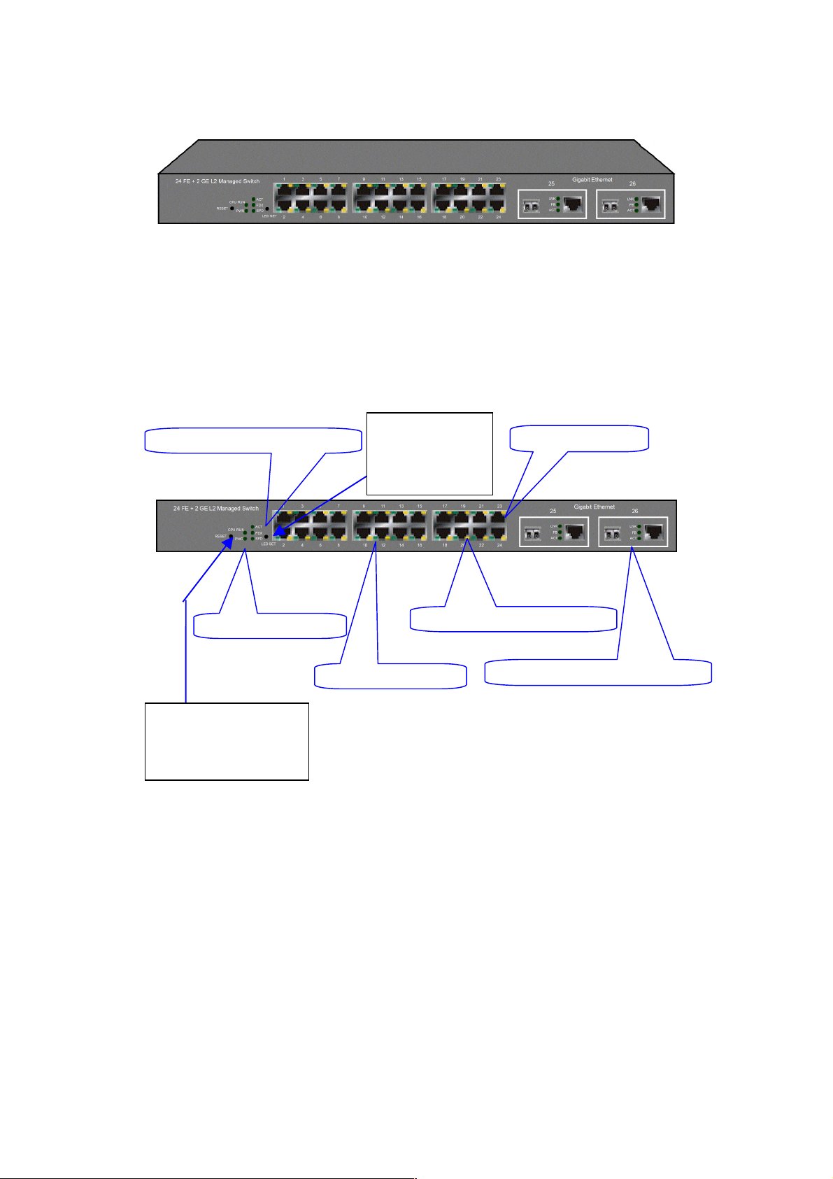
1-4-1. User Interfaces on the Front Panel ( Butt on, LEDs and Plugs)
There are 24 TP Fast Ethernet ports and 2 s lots for optio nal rem ovable m odules on
the front panel of the sw itch. LED displ ay area, loc ating on the fr ont panel, contains
a CPURUN, Power LED and 26 ports working status of the switch.
LED SET Mode: ACT/FDX/SPD
Power Indication LED
RESET Button:
RESET button is used to
reset the management
system.
Fig. 1-2 Front View of the Unit with SFP Module
LEDSET Button
LEDSET button is
used to change
the LED display
mode
TP Port Status: ACT/FDX/SPD
TP Port Status: Link
Fast Ethernet Port
Gigabit Dual Media Port: SFP/TP
10
Page 13

LED Indicators
LED Color Function
System LED
CPURUN Green Lit when CPU is on and good
POWER Green Lit when AC power is on and good
ACT Green Lit when LEDSET set on active mode
FDX Green Lit when LEDSET set on full-duplex mode
SPD Green Lit when LEDSET set on speed mode
10/100Mbps Ethernet TP Port 1 to 24 LED
LNK Green
Amber
ACT/FDX/ SPD
LNK Green
FB Green
ACT/FDX/ SPD
(TP Port 1
to 24 LED)
10/100/1000Mbps Gigabit TP/Fiber Port 25, 26 LED
Green
(Port 25,
26 LED)
Lit when connection with remote device is good
Off when cable connection is not good
a. LEDSET set on ACT (active) mode:
Blinks when any traffic is present
b. LEDSET set on FDX (full-duplex) mode:
Lit when full-duplex mode is active
Blinks when any collision is present
c. LEDSET set on SPD (speed) mode:
Lit when 100Mbps speed is active
Off when 10Mbps speed is active
Lit when connection with remote device is good
Off when cable connection is not good
Lit when Fiber port is active
Off when TP port is active
a. LEDSET set on ACT (active) mode:
Blinks when any traffic is present
b. LEDSET set on FDX (full-duplex) mode:
Lit when full-duplex mode is active
Blinks when any collision is present
c. LEDSET set on SPD (speed) mode:
Lit when 1000Mbps speed is active
Off when 10/100Mbps speed is active
11
Table1-1
Page 14

A
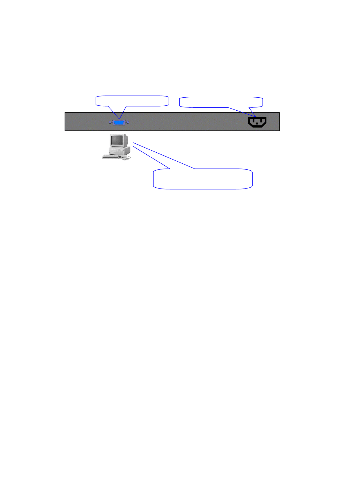
1-4-2. User Interfaces on the Rear Panel
One RS-232 DB-9 interface is offered for configuration or management. And there is
one AC power input socket for having the switch powered on or off.
C Line 100-240V 50/60 Hz
RS-232 DB-9 Connector
Fig. 1-3 Rear View of 24 FAST ETHERNET + 2 GIGABIT L2 MANAGED SWITCH
12
Page 15

1-5. View of the Optional Modules
In the switch, Port 25, 26 includes two types of m edia --- TP and SFP Fiber (LC,
BiDi LC…); this port supports 10/100/1000Mbps TP or 1000Mbps SFP Fiber with
auto-detected function. 1000Mbps SFP Fiber transceiver is used for high-speed
connection expansion. Ref er to “KS-2601 Model List” file for detailed specificati on.
In the list, the SFP fiber tr ansceivers include 10 00BASE-SX standard LC for MMF,
1000BASE-LX LC for different SMF, and Bi-Di LC for single SMF.
Fig. 1-4 Front View of 1000Base-SX/LX LC, SFP Fiber Transceiver
Fig. 1-5 Front View of 1000Base-LX BiDi LC, SFP Fiber Transceiver
13
Page 16

14 15
Page 17
r
2. Installation
2-1. Starting 24 FAST ETHERNET + 2 GIGABIT L2 MANAGED
SWITCH Up
This section will give users a quick start for:
- Hardware and Cable Installation
- Management Station Installation
- Software booting and configuration
2-1-1. Hardware and Cable Installation
At the beginning, please do first:
⇒ Wear a grounding device to avoid the damage from electrostatic discharge
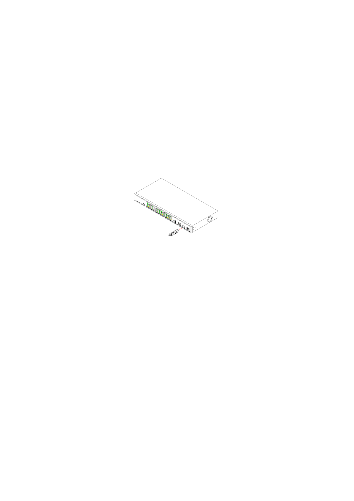
Installing Optional SFP Fiber Transceivers to the L2 Managed Switch
Note: If you have no modules, please skip this section.
Connecting the SFP Module to the Chassis:
The optional SFP modules are hot swappable, so you can plug or unplug it
before or after powering on.
1. Verify that the SFP module is the right model and conforms to the
chassis
2. Slide the module along the slot. Also be sure that the module is properly
seated against the slot socket/connector
3. Install the media cable for network connection
Fig. 2-1 Installation of Optional SFP Fiber Transceive
4. Repeat the above steps, as needed, for each module to be installed into
slot(s)
5. Have the power ON after the above procedures are done
Page 18

TP Port and Cable Installation
⇒ In the switch, TP port supports MDI/MDI-X auto-crossover, so both types of
cable, straight-thro ugh (Cable pin-outs for RJ- 45 jack 1, 2, 3, 6 to 1, 2, 3, 6 in
10/100M TP; 1, 2, 3, 4, 5, 6, 7, 8 to 1, 2, 3, 4, 5, 6, 7, 8 in Gigabit T P) and
crossed-over (Cable pin- outs f or RJ-45 j ack 1, 2, 3, 6 to 3, 6, 1, 2) ca n be use d.
It means you do not have to tell from them, just plug it.
⇒ Use Cat. 5 grade RJ-45 TP cable to connect to a TP port of the s witch and the
other end is connect ed to a network-aware device suc h as a workstation or a
server.
⇒ Repeat the above steps, as needed, for each RJ-45 port to be c onnected to a
Gigabit 10/100/1000 TP device.
Now, you can start having the switch in operation.
Power On
The switch supports 100-2 40 VAC, 50-60 Hz power suppl y. The po wer supply will
automatically convert t he local AC power source to DC po wer. It does not matter
whether any connection plugged into the switch or not when power on, even
modules as well. After the power is on, all LED indica tors will light up immediately
and then all off except the power LED stil l keeps on. This r epresents a reset of the
system.
Firmware Loading
After resetting, the bootstrap loader will load the firmware into the memory. It will
take about 30 seconds, after that, the switch will flash all the LED once and
automatically performs self-test and is in ready state.
16
Page 19

2-1-2. Installing Chassis to a 19-Inch Wiring Closet Rail
Fig. 2-2
Caution: Allow a proper spacing and proper air ventilation for the cooling fan
at both sides of the chassis.
⇒ Wear a grounding device for electrostatic discharge.
⇒ Screw the mounting accessory to the front side of the switch (See Fig. 2-2).
⇒ Place the Chassis into the 19-inch wiring closet rail and locate it at the proper
position. Then, fix the Chassis by screwing it.
2-1-3. Cabling Requirements
To help ensure a success ful installation and keep the net work performance good,
please take a care on the cabling r equirement. Cables with worse specificati on will
render the LAN to work poorly.
17
Page 20
2-1-3-1. Cabling Requirements for TP Ports
⇒ For Fast Ethernet TP network connection
The grade of the cable must be Cat. 5 or Cat. 5e with a maximum length of
100 meters.
⇒ Gigabit Ethernet TP network connection
The grade of the cable must be Cat. 5 or Cat. 5e with a maximum length of
100 meters. Cat. 5e is recommended.
2-1-3-2. Cabling Requirements for 1000SX/LX SFP Module
It is more complex and comprehensive contrast to TP cabling in the fiber media.
Basically, there are two categori es of f iber, multi mode (MM) and s ingl e m ode (SM) .
The later is categor ized into several classes by the distance it supports. T hey are
SX, LX, LHX, XD, and ZX . From the vie wpoint of connector type, there m ainly are
LC and BiDi LC.
Gigabit Fiber with multi-mode LC SFP module
Gigabit Fiber with single-mode LC SFP module
Gigabit Fiber with BiDi LC 1310nm SFP module
Gigabit Fiber with BiDi LC 1550nm SFP module
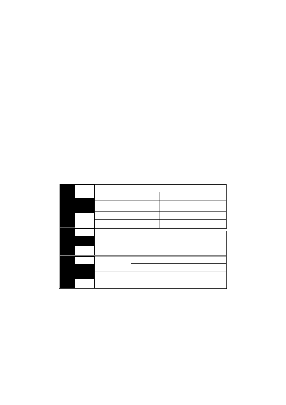
The following table lists the types of fiber that we support and those else not listed
here are available upon request.
Multi-mode Fiber Cable and Modal Bandwidth
IEEE 802.3z
Gigabit Ethernet
1000SX 850nm
1000BaseLX/LHX/XD/ZX
1000Base-LX
Single Fiber
WDM Module
Table2-1
Multi-mode 62.5/125µm Multi-mode 50/125µm
Modal
Bandwidth
160MHz-Km 220m 400MHz-Km 500m
200MHz-Km 275m 500MHz-Km 550m
Single-mode Fiber 9/125µm
Single-mode transceiver 1310nm 10Km
Single-mode transceiver 1550nm 30, 50, 70, 110Km
Single-Mode
*20Km
Single-Mode
*20Km
Distance
TX(Transmit) 1310nm
RX(Receive) 1550nm
TX(Transmit) 1550nm
RX(Receive) 1310nm
Modal
Bandwidth
Distance
18
Page 21

2-1-3-3. Switch Cascading in Topology
Takes the Delay Time into Account
Theoretically, the switch partitions the collision domain for each port in switch
cascading that you m ay up-link the switches unlimitedl y. In pract ice, the network
extension (cascading levels & overall diameter) must follow the constraint of the
IEEE 802.3/802.3u/8 02.3z and other 802.1 seri es protocol specifications, in which
the limitations are the timing requirement from physical signals defined by 802.3
series specificati on of Medi a Access Contr ol (MAC) and PHY, and timer f rom some
OSI layer 2 protocols such as 802.1d, 802.1q, LACP and so on.
The fiber, TP cables and devices’ bit-time delay (round trip) are as follows:
1000Base-X TP, Fiber 100Base-TX TP 100Base-FX Fiber
Round trip Delay: 4096 Round trip Delay: 512
Cat. 5 TP Wire: 11.12/m Cat. 5 TP Wire: 1.12/m Fiber Cable: 1.0/m
Fiber Cable : 10.10/m TP to fiber Converter: 56
Bit Time unit : 1ns (1sec./1000 Mega bit)
Bit Time unit: 0.01µs (1sec./100 Mega bit)
Table 2-2
Sum up all elem ents’ bit-time dela y and the overall bit-time dela y of wires/devices
must be within Round Trip Delay (bit times) in a half-duplex network segment
(collision dom ain). For full-duplex operat ion, this will not be applied. You ma y use
the TP-Fiber module to extend the TP node distance over fiber optic and provide the
long haul connection.
Typical Network Topology in Deployment
A hierarchical network with minim um levels of switch may reduce the tim ing delay
between server and cli ent station. Basically, with this approach, it will minimize the
number of switches in any one path; will lower the possibilit y of network loop and
will improve network efficiency. If more than two switches are connected in the
same network, selec t one switch as Level 1 switch and connect all other switches to
it at Level 2. Ser ver/Host is r ecommended to c onnect to the Le vel 1 switch. This is
general if no VLAN or other special requirements are applied.
19
Page 22
Case1: All switch ports are in the same local area network. Every port can access
each other (See Fig. 2-3).
If VLAN is enab le d and c on f igur ed, eac h n ode i n the n et work that can com municate
each other directly is bounded in the same VLAN area.
Here VLAN area is defined by what V LAN you ar e using. The switch supports b oth
port-based VLAN and tag- based VLAN. They are different i n practical deplo yment,
especially in ph ysical locat ion. The fo llowing diagr am shows ho w it work s and what
the difference they are.
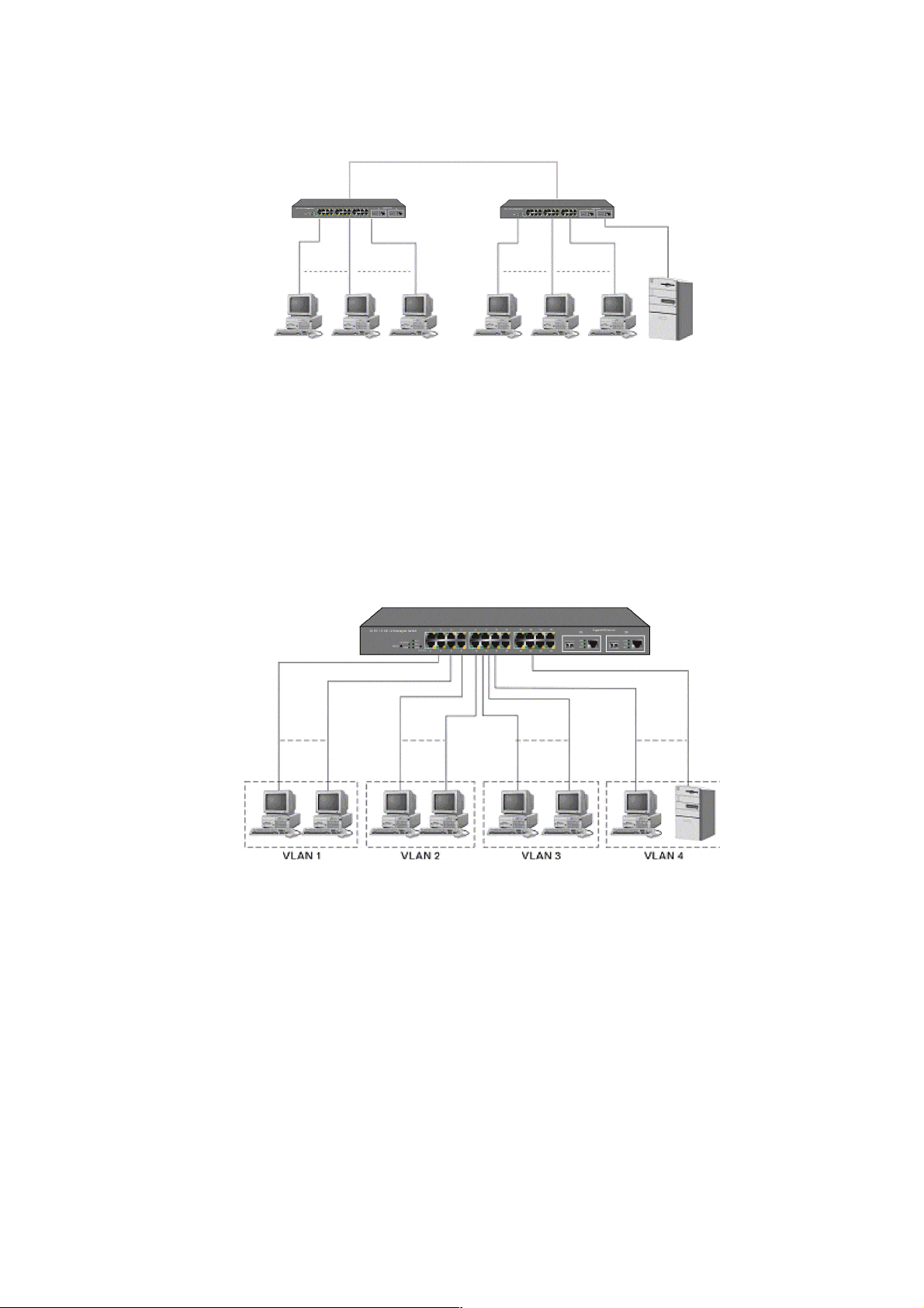
Case2a: Port-based VLAN (See Fig.2-4).
Fig. 2-3 No VLAN Configuration Diagram
1. The same VLAN members could not be in different switches.
2. Every VLAN members could not access VLAN members each other.
3. The switch manager has to assign different names for each VLAN groups
at one switch.
20
Fig. 2-4 Port-based VLAN Diagram
Page 23
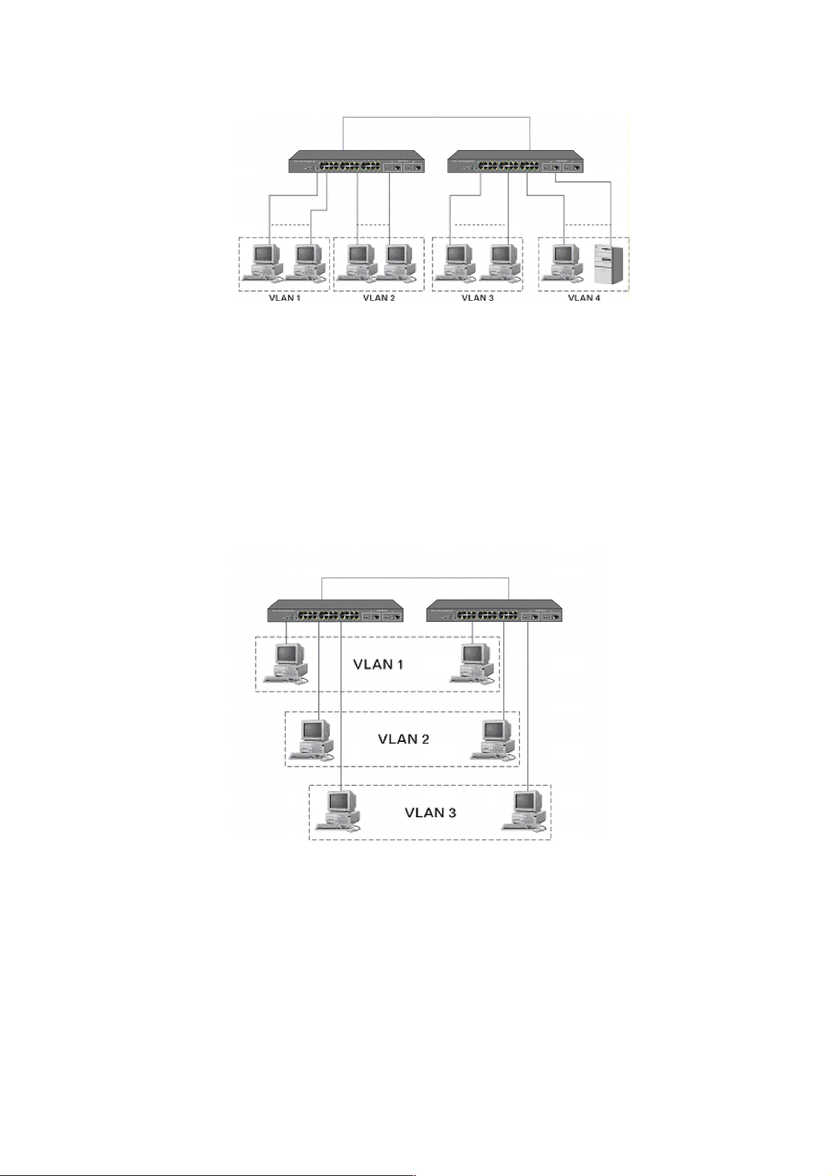
Case 2b: Port-based VLAN (See Fig.2-5).
Fig. 2-5 Port-based VLAN Diagram
1. VLAN1 members could not access VLAN2, VLAN3 and VLAN4 members.
2. VLAN2 members could not access VLAN1 and VLAN3 members, but they could
access VLAN4 members.
3. VLAN3 members could not access VLAN1, VLAN2 and VLAN4.
4. VLAN4 members could not access VLAN1 and VLAN3 members, but they could
access VLAN2 members.
Case3a: The same VLAN members can be at different switches with the same VID
(See Fig. 2-6).
21
Fig. 2-6 Attribute-based VLAN Diagram
Page 24

2-1-4. Configuring the Management Agent of 24 FAST ETHERNET + 2
GIGABIT L2 MANAGED SWITCH
We offer you three ways to startup the switc h management func tion. They are RS232 console, CLI, and Web. Users can use any one of them to monitor and
configure the switch. You can touch them through the following procedures.
Section 2-1-4-1: Configuring the Management Agent of 24 FAST ETHERNET + 2
GIGABIT L2 MANAGED SWITCH through the Serial RS-232 Port
Section 2-1-4-2: Configuring the Management Agent of 24 FAST ETHERNET + 2
GIGABIT L2 MANAGED SWITCH through the Ethernet Port
Note: Please first modify the IP address, Subnet mask, Default gateway and DNS
through RS-232 console, and then do the next.
22
Page 25
r
A
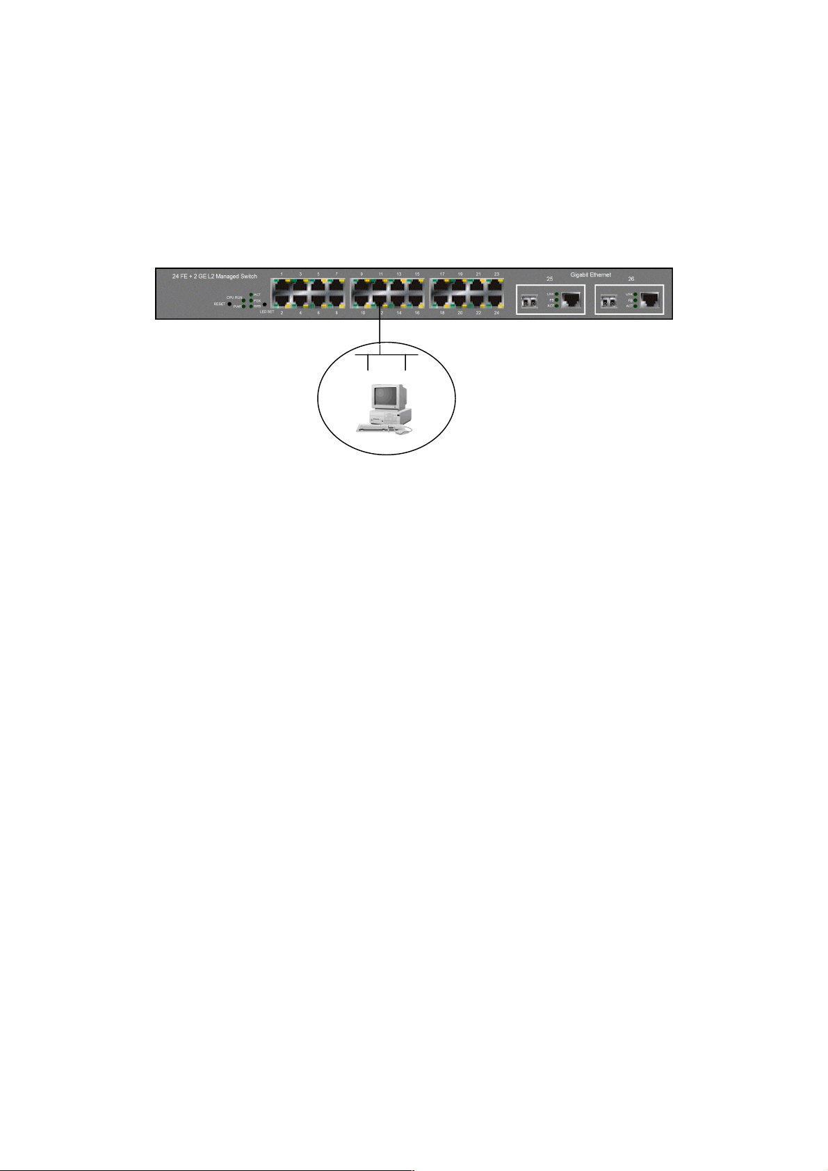
2-1-4-1. Configuring the Management Agent through the Serial RS-232 Port
To perform the configuratio n through RS-232 console port, the s witch’s serial port
must be directl y connected to a DCE device, for exam ple, a PC, through RS-232
cable with DB-9 con nector. Next, run a terminal em ulator with the def ault setting of
the switch’s serial port. With this, you can communicate with the switch.
In the switch, RS-2 32 int er f ac e o nly supports baud rate 57 .6k bps with 8 data bits, 1
stop bit, no parity check and no flow control.
RS-232 DB-9 Connector
C Line 100-240V 50/60 Hz
Terminal or Terminal Emulato
To configure the switch, please follow the procedures below:
1. Find the RS-232 DB-9 cable with female DB-9 connector bundled.
Normally, it just uses pins 2, 3 and 7. See also Appendix B for more
details on Null Modem Cable Specifications.
2. Attaches the DB-9 female cable connector to the male serial RS-232
DB-9 connector on the switch.
3. Attaches the other end of the serial RS-232 DB-9 cable to PC’s serial
port, running a terminal emulator supporting VT100/ANSI terminal with
The switch’s serial port default settings. For example,
Windows98/2000/XP HyperTerminal utility.
Note: The switch’s serial port default settings are listed as follows:
Default IP Setting:
IP address = 192.168.1.1
Subnet Mask = 255.255.255.0
=
RS-232 cable with female
DB-9 connector at both ends
Baud rate 57600
Stop bits 1
Data bits 8
Parity N
Flow control none
Fig. 2-7
4. When you complete the connection, then press <Enter> key. The login
prompt will be shown on the screen. The default username and
password are shown as below:
Username = admin Password = admin
23
Page 26

Set IP Address, Subnet Mask and Default Gateway IP Address
Please refer to F ig. 2-7 C LI Managem ent for detai ls about f actory setting. They ar e
default setting of IP addr ess. You can first either configure your PC IP address or
change IP address of the switc h, next to change the IP address of default gateway
and subnet mask.
For example, your net work address is 10.1.1.0, and s ubnet m ask is 255.255.255 .0.
You can change the s witch’s def ault IP addr ess 192.1 68.1.1 t o 10.1.1.1 and se t the
subnet mask to be 255.255 .255.0. Then, c hoose your default g ateway, may be it is
10.1.1.254.
Default Value 24 FAST Your Network Setting
IP Address
Subnet
Default Gateway
After completing thes e settings i n the s witch, it will reboot to have the co nfiguratio n
taken effect. After this step, you c an operate the m anagem ent through the net work,
no matter it is from a web browser or Network Management System (NMS).
255.255.255.0 255.255.255.0
192.168.1.254 10.1.1.254
Table 2-3
Managed Switch – 2262 FE Switch
Login: admin
Password:
2262 FE Switch
Fig. 2-8 the Login Screen for CLI
24
Page 27
2-1-4-2. Configuring the Management Agent through the Ethernet Port
There are three ways to configure and monitor the switch through the switch’s
Ethernet port. T hey are CLI, Web bro wser and SNMP m anager. The user interface
for the last one is NM S dependent and do es not cover here. W e just introduce the
first two types of management interface.
Default IP Setting:
IP = 192.168.1.1
Subnet Mask = 255.255.255.0
Default Gateway = 192.168.1.254
Ethernet LAN
Assign a reasonable IP address,
For example:
IP = 192.168.1.100
Subnet Mask = 255.255.255.0
Default Gateway = 192.168.1.254
Fig. 2-9
Managing L2 MANAGED SWITCH through Etherne t Port
Before you communicate with the switch, you have to finish first the
configuration of the IP address or to know the IP address of the switch. Then, follow
the procedures listed below.
1. Set up a physical path between the configured the switch and a PC by a
qualified UTP Cat. 5 cable with RJ-45 connector.
Note: If PC directly connects to the switch, you have to setup the same
subnet mask between t hem. But, subnet m ask may be differ ent for the PC
in the remote site. Please refer to Fig. 2-9 about the switch’s default IP
address information.
2. Run CLI or web browser and follow the menu. Please refer to Chapter 3
and Chapter 4.
25
Page 28
3
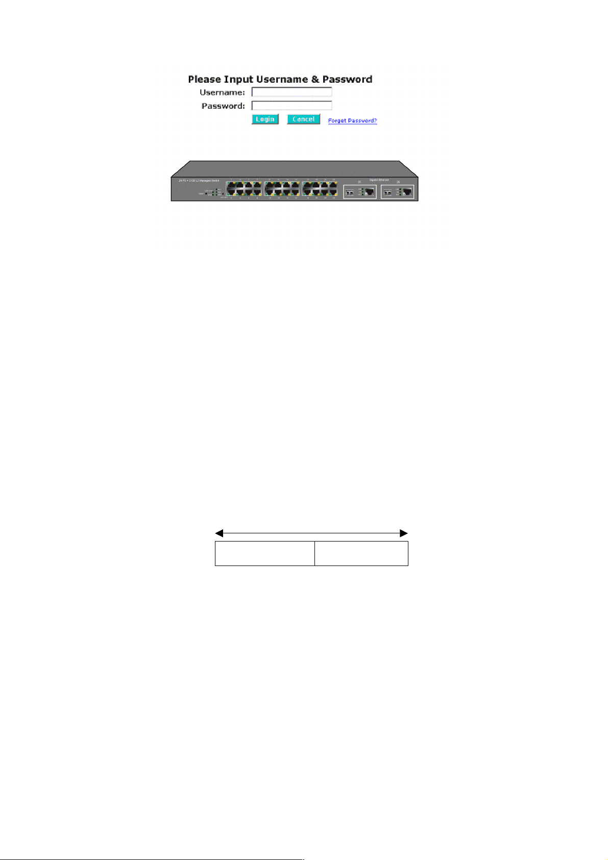
Fig. 2-10 the Login Screen for Web
2-1-5. IP Address Assignment
For IP address configuration, there are three parameters needed to be filled in.
They are IP address, Subnet Mask, Default Gateway and DNS.
IP address:
The address of the network device in the network is used for internetworking
communication. Its addr ess structur e looks is sho wn in the Fig. 2-11. It is “classful”
because it is split into predefined address classes or categories.
Each class has its own network range between the network identifier and host
identifier in the 32 bits address. Each IP address comprises two parts: network
identifier (address ) and host identifier (address). The former indicates the network
where the addressed host resides, and the latter indicates the ind ividual host in t he
network which the addres s of host ref ers to. And the host ident ifier must be unique
in the same LAN. Here the term of IP address we used is version 4, known as IPv4.
2
Network identifier Host identifier
Fig. 2-11 IP address structure
26
Page 29

Netwo
address
ost
Netwo
address
ost
Netwo
address
With the class address ing, it di vides IP address into three clas ses, class A, class B
and class C. The rest of IP addresses are for multicast and broadcast. The bit
length of the network prefix is the sam e as that of the subnet mask and is denoted
as IP address/X, for example, 192.168.1.0/24. Each class has its address range
described below.
Class A:
Address is less than 126.255.255.255. There are a total of 126 networks can be
defined because the a ddres s 0.0.0. 0 is r eserv ed f or d efault ro ute a nd 127.0.0 .0/8 is
reserved for loopback function.
0
Class B:
IP address range betwee n 128.0.0.0 and 191.255.255.25 5. Each class B network
has a 16-bit network prefix followed 16-bit host address. There are 16,384 (2^14)/16
networks able to be defined with a maximum of 65534 (2^16 –2) hosts per network.
Bit # 01 2 15 16
Class C:
IP address range between 192. 0.0.0 and 223.255.255.255. Each class C network
has a 24-bit network prefix followed 8-bit host address. There are 2,097,152
(2^21)/24 networks able to be defined with a maximum of 254 (2^8 –2) hosts per
network.
Bit # 0 1 2 3 23 24
rk
10
rk
H
H
27
110
rk
Page 30

t
N
k
Class D and E:
Class D is a class with firs t 4 MSB (Most s ignificance bit) set to 1-1-1- 0 and is used
for IP Multicast. See also RFC 1112. Class E is a c lass with first 4 MSB se t to 1-1-11 and is used for IP broadcast.
According to IANA (Internet Assign ed Numbers Authority), ther e are three specific
IP address blocks r eserved and able to be used f or extending internal net work. We
call it Private IP address and list below:
Class A 10.0.0.0 --- 10.255.255.255
Class B 172.16.0.0 --- 172.31.255.255
Class C 192.168.0.0 --- 192.168.255.255
Please refer to RFC 1597 and RFC 1466 for more information.
Subnet mask:
It means the sub-d ivision of a class-based ne twork or a CID R block. T he subnet is
used to determine how to split an IP address to the network prefix and the host
address in bitwise basis. It is designed to utilize IP address more efficiently and
ease to manage IP network.
For a class B network, 128.1.2.3 , it may have a subnet mask 255.255 .0.0 i n def au lt,
in which the firs t two bytes is with all 1s. T his means more than 60 thousan ds of
nodes in flat IP address will be at the same network. It’s too large to manage
practically. Now if we divide it into sm aller networ k b y extend ing n et work pr efix from
16 bits to, say 24 bits, that’s using its third byte to s ubnet this class B net work. Now
it has a subnet m ask 255.255.255.0, in which each b it of the first three bytes is 1.
It’s now clear that the fir st t w o bytes is used to ide ntify the class B n et work , the th ir d
byte is used to identify the subnet within this class B network and, of course, the last
byte is the host number.
Not all IP address is a va ila ble in th e s ub-netted network. Two special addresses are
reserved. They are the addresses with all zero’s and all one’s host number. For
example, an IP address 128.1.2. 128, what IP address res erved will be look ed like?
All 0s mean the network itself, and all 1s mean IP broadcast.
10000000.00000001.00000010.1 0000000
28
etwor
25 bits
All 0s = 128.1.2.128
All 1s= 128.1.2.255
Subne
1 0000000
1 1111111
Page 31

In this diagram, you can see the subnet m ask with 25-bit long, 255.255.255.128,
contains 126 members in the sub-netted network. Another is that the length of
network prefix equ als the number of the b it with 1s in that sub net mask. W ith this,
you can easily count the number of IP addresses matched. The following table
shows the result.
Prefix Length No. of IP matched No. of Addressable IP
/32
1 /31
/30
/29
/28
/27
/26
/25
/24
/23
/22
/21
/20
/19
/18
/17
/16
2 -
4 2
8 6
16 14
32 30
64 62
128 126
256 254
512 510
1024 1022
2048 2046
4096 4094
8192 8190
16384 16382
32768 32766
65536 65534
Table 2-4
According to the scheme above, a subnet mask 255.255.255.0 will partition a
network with the class C. It means there will have a maximum of 254 effective
nodes existed in this sub-n etted net work and is c onsid ered a p hysic al net work in an
autonomous network. So it owns a network IP address which may looks like
168.1.2.0.
With the subnet mask , a bigger network can be cut into sm all pieces of network . If
we want to have m ore than two independent networks in a network , a partition to
the network must be performed. In this case, subnet mask must be applied.
29
Page 32

For different network appl ications, the subnet mask may look lik e 255.255.25 5.240.
This means it is a small network accommodating a maximum of 15 nodes in the
network.
Default gateway:
For the routed packet, if the des tina tio n is not i n the rou ting ta ble, al l the tr aff ic is put
into the device with the d esignated IP address, k nown as default r outer. Basically, it
is a routing policy. The gateway setting is used for Trap Events Host only in the
switch.
For assigning an IP address to the switch, you just have to check what the IP
address of the network will be connected with the switch. Use the same network
address and append your host address to it.
Fig. 2-12
First, IP Address: as sho wn in the Fig. 2-12, enter “192.168.1.1”, for instance. F or
sure, an IP address such as 192.168.1.x must be set on your PC.
Second, Subnet Mask: as shown in the Fig. 2-12, enter “255.255.255.0”. Any
subnet mask such as 255.255.255.x is allowable in this case.
DNS:
The Domain Name Server translates human reada bl e machine name to IP ad dress.
Every machine on the Internet has a unique IP addr ess. A server general ly has a
static IP address. To connect to a server, the client needs to know the IP of the
server. However, user generally uses the name to c onnect to the server. Thus, the
switch DNS client program (such as a browser) will ask the DNS to resolve the IP
address of the named server.
30
Page 33

2-2. Typical Applications
The 24 FAST ETHERNET + 2 GIGABIT L2 MANAGED SWITCH implements 24
Fast Ethernet TP ports with auto MDIX and 2 G igabit dual m edia ports with SF P for
removable module supported comprehensive fiber types of connection, including LC,
BiDi LC for SFP. For more details on the specificati on of the switch, please refer to
Appendix A.
The switch is suitable for the following applications.
Central Site/Remote site application is used in carrier or ISP (See Fig. 2-13)
Peer-to-peer application is used in two remote offices (See Fig. 2-14)
Office network(See Fig. 2-15)
Fig. 2-13 Network Connection between Remote Site and Central Site
Fig. 2-13 is a system wide bas ic r ef er ence c onn ec tio n dia gr am. This diagram
demonstrates how the switch connects with other network devices and hosts.
31
Page 34

Fig. 2-14 Peer-to-peer Network Connection
32
Fig. 2-15 Office Network Connection
Page 35

3. Operation of
Web-based Management
This chapter instructs you how to configure and manage the 24 FAST ETHERNET +
2 GIGABIT L2 MANAGED SWITCH through the web user inter face it supports, to
access and manage the 24 10/100Mbps TP + 2 Gigabit dual media ports with
TP/SFP Fiber management Ethernet switch. With this facility, you can easily
access and monitor thro ugh any one port of the switc h all the status of the switch,
including MIBs status, each port activity, Spanning tree status, port aggregation
status, multicast traffic, VLAN an d priority status, eve n illegal access record and so
on.
The default values of the managed switch are listed in the table below:
IP Address
Subnet Mask
Default Gateway
Username
Password
Table 3-1
After the managed switch has been fin ished co nfigurat ion in t he CLI v ia the s witch’s
serial interface, you can browse it. For instance, type http://192.168.1.1
address row in a browser, it will show the following screen (see Fig.3-1) and ask you
inputting usernam e and password in order to login and access authentica tion. The
default username and pas sword are both “admin” . For the first time to use, p lease
enter the default user name and password, and then click the <Login> button. The
login process now is completed.
192.168.1.1
255.255.255.0
192.168.1.254
admin
admin
in the
Just click the link of “Forget Pass word” in W ebUI (See Fig. 3-1) or input “Ctrl+Z” in
CLI’s login screen (See Fig. 4-1~4-2) in case the user forgets the manager’s
password. Then, th e system will displa y a serial No. for the us er. Write down this
serial No. and contact your vendor, the ve ndor will give you a temporar y password.
Use this new pass word as ID and Passwor d, and it will allo w the user to login the
system with manager auth ority temporarily. Due to t he limit of this new password,
the user only can login the system one time, therefore, please modify your
password immediately after you login in the system successfully.
In this login menu, you have to input the complete username and password
respectively, the switch will not give you a shortc ut to username autom atically. This
looks inconvenient, but safer.
33
Page 36

In the switch, it supports a simple user management function allowing only one
administrator to configure the system at the same time. If there are two or more
users using administr ator’s identity, the switch will allow the only one who log ins f ir s t
to configure the system . The rest of users, even with administrator’s identity, can
only monitor the s ystem. For those who have no ad ministrator’s identit y, can o nly
monitor the system. There are only a maximum of three users able to login
simultaneously in the switch.
To optimize the display effect, we recommend you use Microsoft IE 6.0 above,
Netscape V7.1 above or FireFox V1.00 above and have the reso lution 1024x768.
The switch supported neutral web browser interface.
In Fig. 3-2, for example, left section is the whole function tree with web user
interface and we will travel it through this chapter.
34
Fig. 3-1
Page 37

3-1. Web Management Home Overview
After you login, the s witch shows you t he s ystem inf ormation as Fig. 3- 2. This page
is default and tel ls you the bas ic in f orm ation of the system , inc lud ing “ Mo del Name”,
“System Description”, “Location”, “Contact”, “Device Name”, “System Up Time”,
“Current Time”, “BIOS Version”, “Firmware Version”, “Hardware-Mechanical
Version”, “Serial Number”, “H ost IP Address”, “Host MAC Address ”, “Device Port”,
“RAM Size” and “Flash Size”. With this information, you will know the software
version used, MAC ad dres s , s erial n umber, how many ports good and so on. This is
helpful while malfunctioning.
Fig. 3-2
The Information of Page Layout
On the top side, it shows the front panel of the switch. In the front panel, the
linked ports will displ ay green; as to the ports, whic h are link off, they will be
dark. For the optional modules, the slot will show only a cover plate if no
module exists and will show a module if a m odule is present. The image of
module depends on the on e you ins erted. T he same, i f disc onnected, the port
will show just dark, if linked, green.
In this device, there are clicking functions on the panel provided for the
information of th e ports. T hese are very c onvenient f unctions f or browsing t he
information of a single port. When clicking the port on the front panel, an
information window for the port will be pop out. (See Fig. 3-3)
35
Page 38

Fig. 3-3 port detail information
In Fig. 3-3, it shows the bas ic inf or mation of the click ed port. With this, you’ll see th e
information about t he port status, traffic status and bandwidth rating f or egress and
ingress respectively.
On the left-top corner, there is a pull-down lis t for Aut o Logou t. For the s ake of
security, we provide auto-logout function to protect you from illegal user as you
are leaving. If you do n ot choose any selection in Auto Logo ut list, it means
you turn on the Auto Logout function and the system will be logged out
automatically when no action on the devic e 3 minutes later. If OFF is chosen,
the screen will keep as it is. Default is ON.
On the left side, the main m enu tree for web is listed in the page. They are
hierarchical m enu. Open the function folde r, a sub-menu will be shown. The
functions of each fo lder are descr ibed in its cor respon ded sec tion r especti vel y.
When clicking it, the f unctio n is p erf ormed. T he f ollowi ng list is the f ull func tion
tree for web user interface.
36
Page 39

Root
System
Port
SNMP
DHCP Boot
IGMP Snooping
VLAN
MAC Table
GVRP
STP
Trunk
802.1x
Alarm
Configuration
Bandwidth
Diagnostics
Log
Reboot
Security
QoS
TFTP Server
Firmware Upgrade
Logout
37
Page 40

3-1-1. System Information
Function name:
System Information
Function description:
Show the basic system information.
Parameter description:
Model name:
The model name of this device.
System description:
As it is, this tells what this device is. Here, it is “24 Fast Ethernet + 2
Gigabit L2 Managed Switch”.
Location:
Basically, it is the location where this switch is put. User-defined.
Contact:
For easily managing and maintaining device, you may write down the
contact person and ph one here for g etting help s oon. You can configure
this parameter through the device’s user interface or SNMP.
Device name:
The name of the switch. User-defined.
System up time:
The time accum ulated since this switch is powered up. Its f ormat is day,
hour, minute, second.
Current time:
Show the system tim e of the s witch. Its form at: day of week, month, d ay,
hours: minutes: seconds, year. For instance, Tue Apr 20 23:25:58 2004
BIOS version:
The version of the BIOS in this switch.
Firmware version:
The firmware version in this switch.
Hardware-Mechanical version:
The version of Hardware a nd Mechanical. The figure bef ore the hyphen
is the version of electronic hardware; the one after the hyphen is the
version of mechanical.
Serial number:
The serial number is assigned by the manufacturer.
38
Page 41

Host IP address:
The IP address of the switch.
Host MAC address:
It is the Ethernet MAC address of the management agent in this switch.
Device Port:
Show all types and numbers of the port in the switch.
RAM size:
The size of the DRAM in this switch.
Flash size:
The size of the flash memory in this switch.
39
Page 42

3-1-2. IP Configuration
IP configuration is one of the most important configurations in the switch. Without
the proper setting, n etwork m anager will not be able to m anage or vie w the device.
The switch supports both manual IP address setting and automatic IP address
setting via DHCP server. W hen IP address is changed, you must reboot the switch
to have the setting taken eff ect and use the ne w IP to browse f or web m anagement
and CLI management.
Fig. 3-4 IP Address Configuration
Function name:
IP Configuration
Function description:
Set IP address, subnet mask, default gateway and DNS for the switch.
Parameter description:
DHCP Setting:
DHCP is the abbreviation of D ynamic Host Configuration Pro tocol. Here
DHCP means a switch to turn ON or OFF the function.
The switch supports DHCP client used to get an IP address automatically
if you set this f unction “En able”. When ena bled, the switc h will issue the
request to the DHCP server resided i n the network to get an IP address.
If DHCP server is down or does not exist, the switch will issue the
request and show IP address is under requesti ng, until the DHCP server
is up. Before getting an IP address from DHCP server, the device will not
continue booting procedures. If set this field “Disable”, you’ll have to
input IP address m anua lly. For more details abo ut IP a ddr ess an d DHCP,
please see the Section 2-1-5 “IP Address Assignment” in this manual.
Default: Disable
40
Page 43

IP address:
Users can configure the IP settin gs and fill in ne w values if users set the
DHCP function “Disable”. Then, click <Apply> button to update.
When DHCP is disabled, Default: 192.168.1.1
If DHCP is enabled, this field is filled by DHCP server and will not allow
user manually set it any more.
Subnet mask:
Subnet mask is made for the purpose to get more network address
because any IP device in a network must own its IP address, composed
of Network addres s an d Host address , ot her wise c an ’t communicate with
other devices each other. But unfortunately, the network classes A, B,
and C are all too larg e to fit for almost all net works, henc e, subnet m ask
is introduced to solve this problem. Subnet mask uses some bits from
host address and mak es an IP address look ed Netwo rk addres s, Subnet
mask number and ho st address. It is shown in the following figure. T his
reduces the total IP numbe r of a network able to suppor t, by the amount
of 2 power of the bit number of subnet num ber (2 ^ (bit num ber of subne t
number)).
32 bits
Subnet mask is used to set the subnet mask value, which should be th e
same value as t hat of the other devices res ided in the same network it
attaches.
For more information, please also see the Section 2-1-5 “IP Address
Assignment” in this manual.
Default: 255.255.255.0
Default gateway:
Set an IP address for a gateway to handle those packets that do not
meet the routing rules predefined in the device. If a packet does not meet
the criteria for other pre-defined path, it m ust be forwarded to a defau lt
router on a default path. This means any packet with undefined IP
address in the routing table will be sent to this device unconditionally.
Default: 192.168.1.254
Network ID Host ID
Network ID Host ID
Subnet number
41
Page 44

DNS:
It is Domain Name Server used to serve the translation between IP
address and name address.
The switch supports DN S client f unction to re-r oute the m nemonic nam e
address to DNS server to get its associated IP address for accessing
Internet. User can specify a DNS IP address for the s witch. With this, the
switch can translate a mnemonic name address into an IP address.
There are two ways to specify the IP address of DNS. One is fixed mode,
which manually specifies its IP address, the other is dynamic mode,
which is assigned by DHCP server while DHCP is enabled. DNS can
help you easily remember the mnemonic address name with the
meaningful words in it. Default is no assignment of DNS address.
Default: 0.0.0.0
42
Page 45

3-1-3. Time Configuration
The switch provides manual and automatic ways to s et the system time via NTP.
Manual setting is s imple and you just in put “Year”, “Month”, “ Day”, “Hour”, “Minute”
and “Second” within the valid value range indicated in each item. If you input an
invalid value, for example, 61 in minute, the switch will clamp the figure to 59.
NTP is a well-known proto col used to synchronize the clock of the switch s ystem
time over a network . NTP, an internet draft standar d formalized in RFC 1305, has
been adopted on the s ystem is version 3 protoco l. The switch provides four built-in
NTP server IP addresses res ided in the Internet and a user-defined NTP server IP
address. The tim e zone is Greenwich-center ed which uses the expres sion form of
GMT+/- xx hours.
Function name:
Time
Function description:
Set the system tim e by manual input or set it by s yncing from Time servers.
The function also supports daylight saving for different area’s time adjustment.
Parameter description:
Current Time:
Show the current time of the system.
Manual:
This is the functio n to adju st the tim e manuall y. Filling the valid figure s in
the fields of Year, Month, Day, Hour, Minute and Second respective ly and
press <Apply> button, time is adjusted. The valid figures for the
parameter Year, Month, Day, Hour, Minute and Second are >=2000, 1-1 2,
1-31, 0-23, 0-59 and 0-59 r especti vely. Input the wrong figure and press
<Apply> button, the device will rej ect the time adjustment req uest. There
is no time zone setting in Manual mode.
Default: Year = 2000, Month = 1, Day = 1
Hour = 0, Minute = 0, Second = 0
43
Page 46

NTP:
NTP is Network Time Protocol and is used to sync the network time
based Greenwich Mea n Time (GMT). If use the NTP mode and select a
built-in NTP time server or manually specif y an user-def ined NTP server
as well as Time Zone, the switch will sync the time in a short after
pressing <Apply> button. Though it synchronizes th e time autom atically,
NTP does not update the time periodically without user’s processing.
Time Zone is an offset time off GMT. You have to select th e time zone
first and then perform time sync via NTP because the switch will combine
this time zone offs et and updated NTP time to com e out the local time,
otherwise, you will not able to get the correct time. The s witch supports
configurable time zone from –12 to +13 step 1 hour.
Default Time zone: +8 Hrs.
Daylight Saving:
Daylight saving is adopt ed in som e c ountries . If set, it will adjust t he tim e
lag or in adva nce in unit of hours, acc ording to the s tarting date and t he
ending date. For exam ple, if you set the day light saving to be 1 hour.
When the time passes over the starting time, the system time will be
increased one hour after one minute at the time since it passed over. And
when the time passes over the ending time, the system time will be
decreased one hour after one minute at the time since it passed over.
The switch suppor ts valid configurable day lig ht saving time is –5 ~ +5
step one hour. The zero for this parameter m eans it need not have to
adjust current time, equi va l ent to i n-ac t daylight saving. You don’t have to
set the starting/ending date as well. If you set da ylight saving to be nonzero, you have to set the starting/ending date as well; otherwise, the
daylight saving function will not be activated.
Default for Daylight Saving: 0.
The following parameters are configurable for the function Daylight
Saving and described in detail.
Day Light Saving Start :
This is used to set when to start performing the day light saving time.
Mth:
44
Range is 1 ~ 12.
Default: 1
Day:
Range is 1 ~ 31.
Default: 1
Hour:
Range is 0 ~ 23.
Default: 0
Page 47

Day Light Saving End:
This is used to set when to stop performing the daylight saving time.
Mth:
Range is 1 ~ 12.
Default: 1
Day:
Range is 1 ~ 31.
Default: 1
Hour:
Range is 0 ~ 23.
Default: 0
45
Fig. 3-5
Page 48

3-1-4. Account Configuration
In this function, on ly administrator can crea te, modify or delete the username and
password. Administrator can modify other guest identities’ password without
confirming the password but it is necessary to modify the administr ator-equivalent
identity. Guest-equivalent identity can modify his password only. Please note that
you must confirm administrator/gu es t ide nti t y i n t he f ie l d of A uth ori zat ion i n a dv an c e
before configuring the us ername and password. Only one adm inistrator is allowed
to exist and unable to be deleted. In addition, up to 4 guest accounts can be created.
The default setting for user account is:
Username : admin
Password : admin
The default setting for guest user account is:
Username : guest
Password : guest
Fig. 3-6
46
Page 49

3-1-5. Management Security
Through the management security configuration, the manager can do the strict
setup to control the switch and limit the user to access this switch.
The following rules are offered for the manager to manage the switch:
Rule 1) : When no list exists, then it will accept all connections.
Accept
-----------------------------------------------------------------------
Rule 2) : When only “accept lists” exist, then it will deny all connections,
excluding the connection inside of the accepting range.
Accept Deny Accept Deny Accept
-----------------------------------------------------------------------
Rule 3) : When only “deny lists” exist, then it will accept all connections,
excluding the connection inside of the denying range.
Deny Accept Deny Accept Deny
-----------------------------------------------------------------------
Rule 4) : When both “accept and deny” lists exist, then it will deny all
connections, excluding the connection inside of the accepting range.
Accept Deny Deny Deny Accept
-----------------------------------------------------------------------
Rule 5) : When both “accept and deny” lists exist, then it will deny all
connections, excluding the connection inside of the accepting range and NOT
inside of the denying range at the same time.
Accept
Deny
Accept
Deny| Acc | Deny | Acc | Deny
----------------------------------------------------------------------
47
Page 50

Function name:
Management Security Configuration
Function description:
The switch offers Management Security Configuration function. With this
function, the manager c an easily control the mode th at the user connects to
the switch. According to the mode, users can be classified into two types:
Those who are able to connect to the switch (Accept) and those who are
unable to connect to the switch (Den y). Some restric tions also can be p laced
on the mode that th e user connect t o the switch, f or example, we can d ecide
that which VLAN VID is a ble to be accepted or denied by the s witch, the IP
range of the user co uld be ac cepted or den ied by the switch, the port that th e
user is allowed or not allowed to connect with the switch, or the way of
controlling and connecting to the switch via Http, Telnet or SNMP.
Parameter description:
Name:
A name is composed of any letter (A-Z, a-z) and digit (0-9) with maximal
8 characters.
VID:
The switch supports two kinds of options f or managed valid VLA N VID,
including “Any” and “Custom”. Default is “Any”. When you choose
“Custom”, you can fill in VID number. The valid VID range is 1~4094.
48
Fig. 3-7
Page 51

IP Range:
The switch supports t wo kinds of options for m anaged valid IP Range,
including “Any” and “Custom”. Default is “Any”. In case that ”Custom”
had been chosen, you c an assign effective IP r ange. The valid range is
0.0.0.0~255.255.255.255.
Incoming Port:
The switch supports two k inds of options fo r managed valid Port R ange,
including “Any” and “Cus tom”. Default is “ Any”. You can selec t the ports
that you would lik e them to be work ed and restricted in the m anagement
security configuration if ”Custom” had been chosen.
Access T ype:
The switch supports two kinds of options for managed valid Access Type,
including “Any” and “Custom”. Default is “Any”. “Http”, “Telnet” and
“SNMP” are three wa ys for the access an d managing the s witch in case
that” Custom” had been chosen.
Action:
The switch supports two kinds of options for managed valid Action Type,
including “Deny” and “Accept”. Default is “Deny”. When you choose
“Deny” action, you will be restricted and ref used to manage the switch
due to the “Access Type” you choose. However, while you select
“Accept” action, you will have the authority to manage t
he switch.
Edit/Create:
A new entry of Management Security Configur ation can be created after
the parameters as mentioned above had been setup and then press
<Edit/Create> button. Of cours e, the existed entry also c an be modif ied
by pressing this button.
Delete:
Remove the existed entry of Management Security Configuration from
the management security table.
49
Page 52

3-1-6. Virtual Stack
Function name:
Virtual Stack
Function description:
Virtual Stack Management(VSM) is the group m anagement function. Through
the proper configuration of this function, switches in the same LAN will be
grouped automatical ly. And among these s witch, one switch will be a master
machine, and the others in this group will become the slave devices.
VSM offers a simple centrali zed management function. It is not neces sary to
remember the address of all devices; manager is capable of managing the
network with knowing the address of the Master machine. Instead of SNMP or
Telnet UI, VSM is only available in Web UI. While one switch becomes the
Master, two rows of buttons for group de vice will app ear on the top of its Web
UI. By pressing thes e buttons, user will be allowed to c onnect the Web UI of
the devices of the group in the same window without the login of these dev ic es.
The most top-left button is only for Master Device. The background color of the
button you press will be changed to represent t hat the device is under your
management.
Note: It will remove the groupi ng temporaril y in case that you login th e switch
via the console.
The device of the group will be s hown as station addr ess (the last number of
IP Address) + device nam e on the button, otherwise it will show ” ---- “ if no
corresponding device exists.
Once the devices join the group successf ully, then they are m erely able to be
managed via Master device, and user will fail to manage them via
telnet/console/web individually.
Up to 16 devices can be grouped for VSM; however, only one Master is
allowed to exist in each group. For Master redundancy, user may configure
more than two de vices as Master devic e; ho wever, the Master de vice with the
smaller MAC value will be the Master one. All of these 16 devices can
become Master device and back up with each other.
50
Page 53

Parameter description:
State:
It is used for the activation or de-activation of VSM. Default is Enable.
Role:
The role that the switch would lik e to play in virtual stack. Two types of
roles, including master and slave are offered for option. Default is Master.
Group ID:
It is the group ident if ier (G ID) which s igns f or V SM. Valid letters are A-Z ,
a-z, 0-9, “
- “ and “_” characters. The maximal length is 15 characters.
Fig. 3-8
51
Page 54

3-2. Port Configuration
Four functions, inc luding Por t Status, Por t Conf igur ation, Sim ple Counter an d De tail
Counter are contained in this function folder for port monitor and management.
Each of them will be described in detail orderly in the following sections.
Port Configuration
Status
Configuration
Simple Counter
Detail Counter
3-2-1.Port Status
The function Port Status gathers the information of all ports’ current status and
reports it by the order of port number, media, link status, port state, Auto-Negotiation
status, speed/duplex, Rx P ause and T x Pause. An ext ra media t ype inform ation for
the module ports 25 and 26 is also offered.
52
Fig. 3-9
Page 55

Function name:
Port Status
Function Description:
Report the latest updated status of all ports in this switch. When any one of the
ports in the switch changes its parameter displayed in the page, it will be
automatically refreshed the port current status about every 5 seconds.
Parameter Description:
Port No:
Display the port n umber. The number is 1 – 26. Both por t 25 and 26 are
optional modules.
Media:
Show the media t ype adopted in all ports. The Port 25 and Port 26 are
optional modules, which support either fiber or UTP media with either
Gigabit Ethernet (1000Mbps) or 10/100Mbps Fast Ethernet port. They
may have different media types and speed. Especially, fiber port has
comprehensive types of connector, distance, fiber mode and so on. The
switch describes the module ports with the following page.
Link:
Show that if the link on the port is ac tive or not. If the li nk is connec ted to
a working-well device, the Link will show the link “Up”; otherwise, it will
show “Down”. T his is determ ined b y the h ard ware o n both devic es of the
connection.
No default value.
State:
Show that the communication function of the port is “Enabled” or
“Disabled”. When it is enabled, traffic can be transmitted and received via
this port. When it is disabled, no traffic can be transf erred through this
port. Port State is configured by user.
Default: Enabled.
Auto Nego.:
Show the exchange mode of Ethernet MAC. There are two modes
supported in the s witch. They are auto-negotiati on mode “Enabled” and
forced mode “Disabled”. When in “Enabled” mode, this function will
automatically negotiate b y hardware itself and exchange each other the
capability of speed and duplex m ode with other site which is link ed, and
comes out the best c ommunication way. When in “Disabled” mode, b oth
parties must have the same setting of s peed an d dupl ex, oth erwise, both
of them will not be linked. In this case, the link result is “Down”.
Default: Enabled
53
Page 56

Speed / Duplex :
Display the speed and d up l ex of all port. There are thr ee s pee ds 10M bps,
100Mbps and 1000Mbps supported for TP media, and the duplex
supported is half duplex and f ull duplex. If th e media is 1Gbps fiber, it is
1000Mbps supported only. The status of speed/duplex mode is
determined by 1) the negotiation of both local port and link partner in
“Auto Speed” mode or 2) user s etting in “ For ce” mode. The local port h as
to be preset its capability.
In port 1 – 24, they are supporte d Fast Ethernet with TP media onl y, so
the result will show 100M/Full or 100M/Half, 10M/Full and 10M/Half
duplex.
In port 25 and port 26, if the media is 100 0Mbps with TP media, it will
show the combinat ions of 10/100M and Fu ll/Half d uplex , 1000Mbps a nd
Full duplex only. If the media is 1000Mbps with fiber media, it will show
only 1000M/Full duplex.
Default: None, depends on the result of the negotiation.
Rx Pause:
The way that the por t adopts to process the PAUSE frame. If it shows
“on”, the port will car e the PAUSE frame; otherwise, the port will ignore
the PAUSE frame.
Default: None
Tx Pause:
It decides that whether th e port transmits the PAUSE frame or not. If it
shows “on”, the port will send PAUSE frame; otherwise, th e port will not
send the PAUSE frame.
Default: None
54
Page 57

Parameter description of Port 25 and Port 26:
Fig. 3-10
Connector Type:
Display the connector type, for instance, UTP, SC, ST, LC and so
on.
Fiber Type:
Display the fiber mode, for instance, Multi-Mode, Single-Mode.
Tx Central Wavelength:
Display the fiber optical transmitting central wavelength, for
instance, 850nm, 1310nm, 1550nm and so on.
Baud Rate:
Display the maximum baud rate of the fiber module supported, for
instance, 10M, 100M, 1G and so on.
Vendor OUI:
Display the Manufacturer's OUI code which is assigned by IEEE.
Vendor Name:
Display the company name of the module manufacturer.
Vendor P/N:
Display the product name of the naming by module manufacturer.
Vendor Rev (Revision):
55
Display the module revision.
Page 58

Vendor SN (Serial Number):
Show the serial number assigned by the manufacturer.
Date Code:
Show the date this module was made.
Temperature:
Show the current temperature of module.
Vcc:
Show the working DC voltage of module.
Mon1(Bias) mA:
Show the Bias current of module.
Mon2(TX PWR):
Show the transmit power of module.
Mon3(RX PWR):
Show the receiver power of module.
56
Page 59

3-2-2. Port Configuration
Port Configuration is appl ied to c hange t he sett ing of each port. I n th is conf igurat ion
function, you can set/reset the following functions. All of them are described in
detail below.
Fig. 3-11
Function name:
Port Configuration
Function description:
It is used to set each port’s operat io n mode. The switch supports 3 param eter s
for each port. They are State, Speed/Duplex and Flow Control.
Parameter description:
State:
Set the communication capability of the port is Enabled or Disabled.
When enabled, traffic can be transmitted and received via this port.
When disabled, the port is blocked and no traffic can be transferred
through this port. Port State is conf igurable by the user. There are only
two states “Enable” and “Dis able” able t o choos e. If you set a port’s state
“Disable”, then that port is prohibited to pass any traffic, even it looks
Link up.
Default: Enable.
57
Page 60

Speed/Duplex:
Set the speed and duplex of the p ort. In spee d, 10/1 00Mbps bau d rat e is
available for F ast Eth ernet, Gig abit m odule in port 2 5, 26. If the m edia is
1Gbps fiber, it is always 1000Mbps and the duplex is full only. If the
media is TP, the Speed/Duplex is comprised of the com bination of speed
mode, 10/100/1000Mbps, and d uplex mode, full duplex and half duplex.
The following table summarized the function the media supports.
Media type NWay Speed Duplex
100M TP ON/OFF 10/100M Full/Half
1000M TP ON/OFF 10/100/1000M Full for all, Half for 10/100
1000M Fiber ON/OFF 1000M Full
In Auto-negotiation mode, no default value. In Forced mode, default
value depends on your setting.
Flow Control:
There are two modes to c hoose in flow contr ol, includi ng Symm etric and
Asymmetric. If flow control is set Symmetric, both parties can send
PAUSE frame to the transmitting device(s) if the receiving port is too
busy to handle. W hen it is s et Asymm etric, this will let the rece iving por t
care the PAUSE frame from transmitting device(s), but it doesn’t send
PAUSE frame. This is one-way flow control.
Default: Symmetric.
58
Page 61

3-2-3. Port Description
Port Description is a pplied to change the sett ing of each port. In this conf iguration
function, you can give a name to each port. All of them are described in detail
below.
Fig. 3-12
Function name:
Port Description
Function description:
It is used to set each p ort’s description. T his human readable des cription can
make the port management easier.
Parameter description:
Description:
This field can enter up to 47 characters for the port description purpose.
Default: <Empty>.
59
Page 62

3-2-5. Simple Counter
The function of Simple Counter collects any inf ormation and provides the counting
about the traffic of the port, no matter the packet is good or bad.
In the Fig. 3-13, the window can show all ports’ counter information at the same
time. Each data field has 2 0- dig it l ong . If the c ount in g i s overf lo w, the counter will be
reset and restart counting . The data is updated every time inter val defined by the
user. The valid range is 3 to 10 seconds . The Refresh Interval is used to set the
update frequency. Default update time is 3 seconds.
Fig. 3-13
Function name:
Simple Counter
Function description:
Display the summary counting of e ac h port’s traff ic , inc lud ing Tx Byte, Rx B yte,
Tx Packet, Rx Packet, Tx Collision and Rx Error Packet.
Parameters description:
Tx Byte:
Total transmitted bytes.
Rx Byte:
Total received bytes.
Tx Packet:
The counting number of the packet transmitted.
60
Page 63

Rx Packet:
The counting number of the packet received.
Tx Collision:
Number of collisions transmitting frames experienced.
Rx Error Packet:
Number of bad packets received.
61
Page 64

3-2-4. Detail Counter
The function of Detail Counter collects any information and provides the counting
about the traffic of the port, no matter the packet is good or bad.
In the Fig. 3-14, the window can show only one port counter information at the same
time. To see another port’s counter, you have to pull down the list of Select, then
you will see the figures displayed about the port you had chosen.
Each data field has 20-digit long. If the counting is overflow, the counter will be reset
and restart counting. The data is updated every time int erval defined by the user.
The valid range is 3 to 10 seconds. The Refresh Inter val is used to set the update
frequency. Default update time is 3 seconds.
Fig. 3-14
Function name:
Detail Counter
Function description:
Display the detailed counting number of each port’s traffic. In the Fig. 3-14, the
window can show all counter information of each port at one time.
Parameter description:
Rx Packets:
The counting number of the packet received.
Rx Octets:
Total received bytes.
Rx Errors:
Number of bad packets received.
Rx Unicast Packets:
62
Page 65

Show the counting number of the received unicast packet.
Rx Broadcast Packets:
Show the counting number of the received broadcast packet.
Rx Multicast Packets:
Show the counting number of the received multicast packet.
Rx Pause Packets:
Show the counting number of the received pause packet.
Tx Collisions:
Number of collisions transmitting frames experienced.
Tx Single Collision:
Number of frames transmitted that experienced exactly one collision.
Tx Multiple Collision:
Number of frames transmitted that experienced more than one collision.
Tx Drop Packets:
Number of frames dropped due to excessive collision, late collision, or
frame aging.
Tx Deferred Transmit:
Number of frames delayed to transmission due to the medium is busy.
Tx Late Collision:
Number of times that a collision is detected later than 512 bit-times into
the transmission of a frame.
Tx Excessive Collision:
Number of frames that are not transmitted because the frame
experienced 16 transmission attempts.
Packets 64 Octets:
Number of 64-byte frames in good and bad packets received.
Packets 65-127 Octets:
Number of 65 ~ 127-byte frames in good and bad packets received.
Packets 128-255 Octets:
Number of 128 ~ 255-byte frames in good and bad packets received.
Packets 256-511 Octets:
Number of 256 ~ 511-byte frames in good and bad packets received.
Packets 512-1023 Octets:
Number of 512 ~ 1023-byte frames in good and bad packets received.
Packets 1024- 1522 Octets:
Number of 1024-1522-byte frames in good and bad packets received.
63
Page 66

Tx Packets:
The counting number of the packet transmitted.
TX Octets:
Total transmitted bytes.
Tx Unicast Packets:
Show the counting number of the transmitted unicast packet.
Tx Broadcast Packets:
Show the counting number of the transmitted broadcast packet.
Tx Multicast Packets:
Show the counting number of the transmitted multicast packet.
Tx Pause Packets:
Show the counting number of the transmitted pause packet.
Rx FCS Errors:
Number of bad FSC packets received.
Rx Alignment Errors:
Number of Alignment errors packets received.
Rx Fragments:
Number of short frames (< 64 bytes) with invalid CRC.
Rx Jabbers:
Number of long frames (according tomax_length register) with invalid
CRC.
Rx Drop Packets:
Frames dropped due to the lack of receiving buffer.
Rx Undersize Packets:
Number of short frames (<64 Bytes) with valid CRC.
Rx Oversize Packets:
Number of long frames (according to max_length register) with valid
CRC.
64
Page 67

3-3. SNMP Configuration
Any Network Management System (NMS) running the Simple Network
Management Protocol (SNMP) can manage the Managed devices equipped with
SNMP agent, provided that the Management Information Base (MIB) is installed
correctly on the manage d devices. The SNMP is a protocol t hat is used to govern
the transfer of information between SNMP manager and agent and traverses the
Object Identity (OID) of the management Information Base (MIB), described in the
form of SMI syntax. SNMP agen t is running on the switc h to response the reques t
issued by SNMP manager.
Basically, it is passive except issuing the trap information. The switch supports a
switch to turn on or off the SNMP age nt. If you set t he field SNMP “Ena ble”, SNMP
agent will be started up. All supported MIB OIDs, including RMON MIB, can be
accessed via SNMP m anager. If the field SNMP is set “Disabl e”, SNMP agent will
be de-activated, the relate d Community Name, Trap Host IP Address, Trap and all
MIB counters will be ignored.
Function name:
SNMP Configuration
Function description:
This function is used to configure SNMP settings, c ommunity name, trap hos t and
public traps as well as the throttle of SNMP. A SNMP manager must pass the
authentication by identifying both community names, and then it can access the MIB
information of the target d evice. So, both parties must have the same c ommunity
name. Once completing the setting, click <Apply> button, the setting takes effect.
Parameters description:
SNMP:
The term SNMP here is used for the ac tivation or de- activati on of SNMP.
Default is Enable.
Get/Set/Trap Community:
Community name is used as password for authenticating if the
requesting network management unit belongs to the same community
group. If they both don’t have the same community name, they don’t
belong to the same group. Hence, the requesting network management
unit can not access the devic e with differ ent community name via SNMP
protocol; If they both have the same community name, they can talk each
other.
Community name is user-definable with a maximum length of 15
characters and is c ase se ns itive. T her e is not a llo wed to pu t an y blank in
the community name string. Any printable character is allowable.
The community name for each function works independently. Each
function has its own community name. Say, the community name for
GET only works for GET function an d can’t be applied to other f unction
such as SET and Trap.
65
Page 68

Default SNMP function: Enable
Default community name for GET: public
Default community name for SET: private
Default community name for Trap: public
Default Set function: Enable
Default trap host IP address: 0.0.0.0
Default port number: 162
Trap:
In the switch, there are 6 tr ap hos ts support ed. Each of them has its own
community name and IP ad dres s; is us er-def inabl e. To set up a trap host
means to create a trap m anager by assignin g an IP address to hos t the
trap message. In other words, the trap host is a network management
unit with SNMP manager recei ving the trap mess age from the managed
switch with SNMP agent issuing the trap message. 6 trap hosts can
prevent the important trap message from losing.
For each public trap, the sw itch supp orts the trap eve nt Cold Start, Warm
Start, Link Down, Link Up and Authenticat ion Failure Trap. They can be
enabled or disabled individually. When enabled, the corresponded trap
will actively send a trap m es sage to the tr a p hos t when a trap happens. If
all public traps are disabl ed, no public trap message will be sent . As to
the Enterprise (no. 6) trap is classif ied as private trap, which are lis ted in
the Trap Alarm Configuration function folder.
Default for all public traps: Enable.
Fig. 3-15 Community and trap host setting
66
Page 69

3-4. Loop Detection
Looping will always occur when the switches are connected as a cycle and a switch
transmits the packets that will go back to the transmitted switch. Loop Detection will
prevent the looping from happening. Moreover, it could remove the looping
phenomenon per port. In general, you can unplug the cable connection to stop the
looping when a port causes the looping. The switch has powerful Looping Detection
capability, which could cease the looping immediately.
Function name:
Loop Detection
Function description:
This function will start when you enable looping action by ticking the
check box () of the Action. That will create some special packet for
67
Fig. 3-16 Loop Detection
Page 70

looping detection. After enabling looping action, you should decide which
port you would like to open loop detection capability. For example, you
open the loop detection of port 1 as enable state. When the looping
situation happens from port 1, Loop Detection will lock the port1’s ability.
And then you will see that the “Current Status” of port 1 shows Locked. In
port status function, you can see that the State of Port Configuration of
port 1 is “Disabled”. So the port 1 will lose the essential ability the port
could have. However, “Resume Action” in Loop Detection will remove the
looping status. It is very convenient for looping happening in real
networking environment. After any setting you done, please click the
<Apply> button to have the setting taken effect. When looping has
already happened, we suggest that the users could choose the looping
port as “Enable” in advance. And then tick the check box () of the
Action. That will get the better result for Looping removing.
Parameters description:
State:
Open the Loop Detectio n capability per port. The list has “Enabl e” and
“Disable”. Default is “Disable”.
Current Status:
Show the looping status per port. It could be “Unlocked or Locked”.
Default is “Unlocked”. When some port happens looping, it will show
“Locked”
Resume Action:
Remove the looping status per port. Just tick the check box () of the
Unlock to open resume action per port.
Refresh:
“Refresh” button could appear the instant Current Status of Loop
Detection.
68
Page 71

3-5. DHCP Boot
The DHCP Boot function is used to spread the request broadcast packet into a
bigger time fr ame to prevent the traffic congestion d ue to broadcast packets from
many network devices which may seek its NMS, boot server, DHCP server and
many connections predef ined when the who le building or block lose the power and
then reboot and recover. At this mom ent, a bunch of s witch or other network device
on the LAN will tr y its best to find the server to get the services or try to set u p the
predefined links, they will issue many broadcast packets in the network.
The switch supports a random dela y time f or DHCP and boot delay for each de vice.
This suppresses th e broadcast storm while all devices are at boo ting stage in the
same time. The m axim um user-def ined de lay tim e is 30 s ec. If DHCP Broadcast ing
Suppression function is enabled, the delay time is s et randomly, ranging from 0 to
30 seconds, because t he exactly delay time is computed b y the switch itself. The
default is “Disable”.
Fig. 3-17
69
Page 72

3-6. IGMP Snooping
The function, IGMP Snooping, is used to establish the multic ast groups to forward
the multicast packet to the member ports, and, in nature, avoids wasting the
bandwidth while IP multica st packets ar e running o ver the net work . This is bec ause
a switch that does not support IG MP or IGMP Snooping can not tell the multicast
packet from the broadcast packet, so it can only treat them all as the broadcast
packet. Without IGMP Snooping, the multicast packet forwarding function is plain
and nothing is different from broadcast packet.
A switch supported IGMP Snooping with the func tions of quer y, report and leav e, a
type of packet exchanged b etween IP Multicast Router/ S witch and IP Multicast Host,
can update the information of the Multicast table when a member (port) joins or
leaves an IP Multicast Destination Address. With this function, once a switch
receives an IP multicast packet, it will forward the packet to the members who
joined in a specified IP multicast group before.
The packets will be discard ed by the IGMP Snoopin g if the user tr ansmits multicas t
packets to the multicast group that had not been built up in advance.
Fig. 3-18
Function name:
IGMP Snooping Status
Function description:
IGMP is used to snoop the status of IP multicast groups and display its
associated inform ation in both tagged VLAN and non- tagged VLAN net works.
Enabling IGMP with ei ther passive or active mode, you can monitor the IGMP
snooping information, which contains the multicast member list with the
multicast groups, VID and member port.
70
Page 73

Parameter description:
IGMP snooping mode selection:
The switch supports three kinds of IGMP Snooping status, including
“Passive”, “Active” and “Disable”.
Disable:
Set “Disable” mode to disable IGMP Snooping function.
Default: Disable
Active:
In Active mode, IGMP snooping s witch will periodical ly issue t he
Membership Query message to all hosts attached to it and
gather the Member ship report message to up date the database
of the Multicast table. By the way, this also reduces the
unnecessary multicast traffic.
Passive:
In Passive Snooping mode, the IGMP snooping will not
periodically poll the hosts in the groups. The switch will send a
Membership Query message to all hosts only when it has
received a Membership Query message from a router.
IP Address:
Show all multicas t gr oups I P addres s es th at are registered on this device.
VLAN ID:
Show VLAN ID for each multicast group.
Member Port:
Show member ports that join each multicast group. Member port may be
only or more than one.
71
Page 74

Function name:
Allowed Group
Function description:
The Allowed Group function allows the IGMP Snooping to set up the IP
multicast table bas ed on user’s spec ific conditions. I GMP report packets that
meet the items you set up will be joined or formed the multicast group.
Parameter description:
IP Range:
The switch supports two kinds of options for managed valid IP range,
including “Any” an d “Custom”. Default is “ Any”. In case that ”Custom ” is
chosen, you can assign effective IP range. The valid range is
224.0.0.0~239.255.255.255.
VID:
The switch supports two kinds of options f or managed valid VLA N VID,
including “Any” and “Custom”. Default is “Any”. When you choose
“Custom”, you can fill in VID number. The valid VID range is 1~4094.
Port:
The switch supports two kinds of options f or managed valid por t range,
including “Any” and “Cus tom”. Default is “ Any”. You can selec t the ports
that you would like them to work and be restricted in the allo wed group
configuration if ”Custom” is chosen.
72
Fig. 3-19
Page 75

Add:
A new entry of
parameters as mentioned above had been s etup and then pr ess <Add>
button.
Edit:
The existed entry also can be modified after pressing <Edit> button.
Delete:
Remove the existed entry of allowed group configuration from the
allowed group.
allowed group configuration can be created after the
73
Page 76

3-7. VLAN
The switch supports Tag-based VLAN (802.1q) and Por t-based VLAN. It supports
256 active VLANs and VLAN ID 1~4094. VLAN configuration is used to partition
your LAN into sm all ones a s your dem and. Pro perly c onfiguring it, you c an gain not
only improving security and increasing performance but greatly reducing VLAN
management.
3-7-1. VLAN Mode
Function name:
VLAN Mode Setting
Function description:
The VLAN Mode Selecti on function includ es two modes: Port- based and Tagbased, you can choose one of them by pulling down list and pressing the
<Downward> arrow key. Then, click <Apply> button, the settings will take
effect immediately.
Parameter description:
VLAN Mode:
Tag-based:
This is the default setting.
Tag-based VLAN identifies its member by VID. This is quite
different from port-based VLAN. If there are any more rules in
ingress filtering list or egress filtering list, the packet will be
screened with more filtering criteria to determine if it can be
forwarded. The switch supports supplement of 802.1q.
Each tag-based VLAN you built up must be assigned VLAN name
and VLAN ID. Valid VLAN ID is 1-4094. Us er can crea te total up to
256 Tag VLAN groups.
Port-based:
Port-based VLAN is defined by port. Any packet coming in or
outgoing from an y one port of a port-bas ed VLAN will be acc epted.
No filtering criterion ap plies in port-based VLAN. T he only criterion
is the physical por t you connect to. For exam ple, for a port-based
VLAN named PVLAN-1 contains port members Port 1&2&3&4. If
you are on the port 1, you can communicate with por t 2 &3 &4. If you
are on the port 5, then you cannot talk to them. Each port-based
VLAN you built up must be assigned a group name. This switch can
support up to maximal 26 port-based VLAN groups.
Metro Mode:
The Metro Mode is a quick configuration VLAN environment
method on Port-based VLAN. It will create 22 or 23 Port-based
VLAN groups.
74
Page 77

Symmetric Vlan:
This is an Ingress Rule (Rule 1, T he Ingress Filterin g Rule 1 is “for ward
only packets with VID matching this port’s configured VID”.). For example,
if port 1 receives a tagge d pack et with V ID=10 0 (VLA N nam e=VLAN 100),
and if Symmetr ic-Vlan function is ena bled, the switch will chec k if port 1
is a member of VLAN100. If yes, the received packet is forwarded;
otherwise, the received packet is dropped.
Note: If Symmetric is enabl ed and por t 1, for ex am ple, receives an untagg ed pack et,
the switch will apply the PVID of port 1 to tag this packet, the packet then will
be forwarded. But if the PVID of port 1 is not 100, the packet will be dropped.
SVL:
While SVL is enable, all VLANs use the sam e filtering database s toring
the membership information of the VLAN to learn or look up the
membership information of the VLAN. While SVL is disable, it means
learning mode is IVL. In th is mode, differ ent VLAN uses differ ent filtering
database storing the membership information of the VLAN to learn or
look up the information of a VLAN member.
Double Tag:
Double-tag mode belongs to the tag-b ased m ode, ho wever, it would treat
all frames as the untagge d ones, which m eans that tag with PVID will be
added into all packets. Then, these packets will be forwarded as Tagbased VLAN. So, the inco ming packets with tag will becom e the doubl etag ones. To notice that the up-link Port won’t add an extra VLAN tag.
Up-link Port:
This function is enabled only when metro mode or double-tag is chosen
in VLAN mode.
25:
Except Port 25, each port of the switch cannot transmit packets with
each other. Each port groups a VLAN with Port 25, thus , total 23
groups consisting of 2 members are formed.
26:
Except Port 26, each port of the switch cannot transmit packets with
each other. Each port groups a VLAN with Port 26, thus , total 23
groups consisting of 2 members are formed.
25&26:
Except Port 25 and Port 2 6, eac h por t of the sw itch ca nnot tr ansm it
packets with each other. Each port groups a VLAN with Port 25
and Port 26, thus, total 22 groups consisting of 3 members are
formed.
75
Page 78

Fig. 3-20
76
Page 79

3-7-2. Tag-based Group
Function name:
Tag-based Group Configuration
Function description:
It shows the information of existed Tag-based VLAN Groups. You can also
easily create, edit and delete a Tag-based VLAN group b y pressing <Add>,
<Edit> and <Delete> function buttons. User can add a new VLAN group by
inputting a new VLAN name and VLAN ID after pressing <Add> button.
Parameter description:
VLAN Name:
The name defined by administrator is associated with a VLAN group.
Valid letters are A-Z, a-z, 0-9, “
length is 15 characters.
VID:
VLAN identifier. Each tag-based VLAN group has a unique VID. It
appears only in tag-based and Double-tag mode.
Member:
- “ and “_” characters. The maximal
This is used to enable or disable if a port is a mem ber of the new added
VLAN, “Enable” m eans it is a member of the VLAN. Just tick the check
box beside the port x to enable it.
Fig. 3-21
77
Page 80

Add Group:
Input the VLAN nam e, VID and then cho ose the member b y ticking the
check box beside the por t No. to create a new Tag-based VLAN. As t o
the parameter of Untag, it stands for an egres s ru le of the port. If you tick
the check box beside t he port No., packets with this VID outgoi ng from
this port will be untagged. F inally, press the <Apply> button to have the
setting taken effect.
Fig. 3-22
Delete Group:
Just press the <Delete> button to remove the selected group entry from
the Tag-based group table.
Edit a group:
Just select a group entry and press the <Edit> button, then you can
modify a group’s description, member and untag settings.
78
Page 81

3-7-3. PVID
Function name:
PVID
Function description:
In PVID Setting, user can inp ut VID number to each port. The range of VID
number is from 1 to 4094. User also c an choose ingress f iltering ru le (Rule 2)
to each port. The Ingress Filtering Rule 2 is “drop untagged frame”. While Rule
2 is enabled, the port will discard all Untagged-frames.
Fig. 3-23
Parameter description:
Port 1-26:
Port number.
PVID:
This PVID range wi ll be 1- 4 094. B ef or e you se t a number x as P VID, you
have to create a Tag-based VLAN with VID x. For example, if port x
receives an untagged packet, the s witch will apply the P VID (assum e as
VID y) of port x to tag this pack et, the packet then will be forwarded as
the tagged packet with VID y.
Default Priority:
79
Page 82

Drop Untag:
It bases on 802.1p QoS an d affec ts untagged pack ets. W hen the packets
enter the switch, it would get the priority precedenc e according to your
Default Priority set tin g an d map to 802.1p priority set ti ng in QoS function.
For example, while you set Default Priority of por t 2 with 2 and transmit
untagged packets to port 2, these pack ets will own prior ity 2 precedence
due to your defau lt 802.1p Priorit y Mapping setting in QoS function an d
be put into Queue 1.
Drop untagged frame. You can configure a given port to accept all frames
(Tagged and Untagged) or j ust receive tagged frame. If the form er is the
case, then the packets with tagged or untagged will be processed. If the
later is the case, only the packets carr ying VLAN tag will be pr ocessed,
the rest packets will be discarded.
80
Page 83

3-7-4. Port-based Group
Function name:
Port-based Group Configuration
Function description:
It shows the information of the existed Port-based VLAN Groups. You can
easily create, edit and de lete a Port-based VLAN group b y pressing <Add>,
<Edit> and <Delete> function buttons. User can add a new VLAN group by
inputting a new VLAN name.
Parameter description:
VLAN Name:
The name defined by administrator is associated with a VLAN group.
Valid letters are A-Z, a-z, 0-9, “
length is 15 characters.
Member:
This is used to enable or disable if a port is a mem ber of the new added
VLAN, “Enable” m eans it is a member of the VLAN. Just tick the check
box beside the port x to enable it.
- “ and “_” characters. The maximal
81
Fig. 3-24
Page 84

Add Group:
Delete Group:
Edit a group:
Create a new Port-based VLAN. Input the VLAN name and c hoose the
member by ticking the check box beside the port No., then, press the
<Apply> button to have the setting taken effect.
Fig. 3-25
Just press the <Delete> button to remove the selected group entry from
the Port-based group table.
Just select a group entry and press the <Edit> button, then you can
modify a group‘s description and member set.
82
Page 85

3-7-5. Management VLAN
Function name:
Management VLAN
Function Description:
Parameter description:
State:
It works when the tag-based mode is chosen. When this function is
enabled, only the tagged packets with this VID can manage the switch.
VID:
Valid range 1~4094.
83
Page 86

3-8. MAC Table
MAC Table Configuration gathers many functions, including MAC Table Information,
MAC Table Maintenance, Static and MAC Alias, which cannot be categorized to
some function type. They are described below.
Function name:
MAC Table Information
Function Description:
Display the static or dynamic learning MAC entry and the state for the selected
port.
Parameter description:
Port:
Select the port you would like to inquire.
Search:
Set up the MAC entry you would like to inquire.
The default is ??-??-??-??-??-??
MAC:
Display the MAC address of one entry you selected from the searched
MAC entries table.
Alias:
Set up the Alias for the selected MAC entry.
Set Alias:
Save the Alias of MAC entry you set up.
Search:
Find the entry that meets your setup.
Previous Page:
Move to the previous page.
Next Page:
Move to the next page.
Alias:
The Alias of the searched entry.
MAC Address:
The MAC address of the searched entry.
84
Page 87

Port:
The port that exists in the searched MAC Entry.
VID:
VLAN Group that MAC Entry exists.
State:
Display the method that this MAC Entry is built. It may show “Dynamic
MAC” or “Sta tic MAC”.
Fig. 3-26
85
Page 88

Function Name:
MAC Table Maintenance
Function Description:
This function can allo w the user to set up the proc essing mechanism of MAC
Table. An idle MAC address exceeding MAC Address Age-out Time will be
removed from the MAC Table. The range of Age-out Time is 10-1000000
seconds, and the setup of this time will have no effect on static MAC
addresses.
In addition, the lear ning limit of MAC m aintenance is able to limit the amount
of MAC that each port can learn.
Parameter description:
Aging Time:
Delete a MAC address idling for a period of time fr om the MAC Table,
which will not aff ect static MAC address. Ra nge of MAC Addres s Aging
Time is 10-1000000 seconds. The default Aging Time is 300 seconds.
Learning Limit:
To set up the maximum amount of MAC that eac h port can learn. Valid
value of learning limit for port 1~24 ranges from 0-8191. As to port
25~port 26, only the fixed value “8192” is assigned to these two ports
and user cannot configure this value.
86
Fig. 3-27
Page 89

Function Name:
Static Setting
Function Description:
The function of Stat ic is used to configur e MAC’s real manners i nside of the
switch. Three kinds of manners including static, static with destination drop
and static with source drop are contained in this function .
As “static” is chosen, assign a MAC address to a specific port, all of the
switch’s traffics sent to this MAC address will be forwarded to this port.
As “static with desti nation d rop” is c hosen, th e packet wil l be droppe d if its D A
is equal to the value you set up. Due to t his setting belongs to the gl obal one,
so, it may affect all ports’ transmission of the packets.
As “static with sourc e drop” is chosen, the pack et will be dropped if its SA is
equal to the value you set u p. Due to this setting belon gs to the gl oba l on e, so,
it may affect all ports’ transmission of the packets.
Parameter description:
MAC:
It is a six-byte long Etherne t hard ware addres s and us uall y express ed b y
hex and separated by hyphens. For example,
00 – 40 - C7 - D6 – 00 - 01
VID:
VLAN identifier. This will be filled only when tagged VLAN is applied.
Valid range is 1 ~ 4094.
Fig. 3-28
87
Page 90

Queue (Priority):
Set up the priority ( 0~3) for the MAC.
Forwarding Rule (Drop Policy):
Static:
A MAC address is assigned to a specific port, all of the switch’s
traffics sent to this MAC address will be forwarded to this port.
Static with Destination Drop:
While the DA of the incoming packets meets the value you set up,
these packets will be dropped.
Static with Source Drop:
While the SA of the incoming packets meets the value you set up,
these packets will be dropped.
Port :
Select the port No. you would like to do setup in the switch. It is 1 ~26.
88
Page 91

Function name:
MAC Alias
Function description:
MAC Alias function is used to let you assign MAC address a plain English
name. This will help you tel l which MAC address bel ongs to which user i n the
illegal access repor t. At the initial time, it shows all pair s of the existed alias
name and MAC address.
There are three MAC alias functions in this function folder, including MAC Alias
Add, MAC Alias Edit and MAC Alias Delete. You can click <Create/Edit>
button to add/modify a new or an existed alias name for a specified MAC
address, or m ark an existed entr y to delete it. Alias na me must be com posed
of A-Z, a-z and 0-9 only and has a maximal length of 15 characters.
Function name:
MAC Alias Create/Edit or Delete
Function description:
In the MAC Alias function, MAC Alias Add/E dit function is us ed to let you add
or modify an association between MAC address and a plain English name.
User can click <Create/Edit> button to add a new record with name.
As to MAC Alias Del ete function is used to le t you re move an alias name to a
MAC address. You can select an existed MAC address or alias name to
remove.
89
Fig. 3-29
Page 92

Parameter description:
MAC Address:
It is a six-byte long Etherne t hard ware addres s and us uall y express ed b y
hex and separated by hyphens. For example,
00 – 40 - C7 - D6 – 00 - 02
Alias:
MAC alias name you assign.
Note: If there are too many MAC addresses learned in the table, we recommend
you inputting the MAC address and alias name directly.
90
Page 93

3-9. GVRP Configuration
GVRP is an application based on Gener ic Attribute Registration Protoco l (GARP),
mainly used to automatically and dynamically maintain the group membership
information of the VLANs. The GVRP offers the function providing the VLAN
registration serv ice throug h a G ARP applicati on. It m akes us e of GARP Inf ormation
Declaration (GID) to maintain the ports associated with their a ttribute database and
GARP Information Propagation (GIP) to communicate among switches and end
stations. With GID inform ation and GIP, GVRP state machine maintain the c ontents
of Dynamic VLAN Registration Entries for each VLAN and propagate these
information to other GVRP-aware devices to setup and update their knowledge
database, the set of VLANs ass ociated with c urrently ac tive mem bers, and throu gh
which ports these members can be reached.
In GVRP Configuration function folder, there are three functions supported,
including GVRP Config, GVRP Counter and GVRP Group explained below.
91
Fig. 3-30
Page 94

Function name:
GVRP Config
Function description:
In the function of GVRP Config, it is used to configure each port’s GVRP
operation mode, in which there are seven parameters needed to be configured
described below.
Parameter description:
GVRP State Setting:
This function is sim ply to let you enable or disable GVRP func tion. You
can pull down the list and click the <Downward> arro w key to choose
“Enable” or “Disable”. Then, click the <Apply> button, the system will
take effect immediately.
Join Time:
Used to declare th e Join Time in unit of centisecond. Vali d time range:
20 –100 centiseconds, Default: 20 centisecond.
Leave Time:
Used to declare the Leave Time in unit of centiseco nd. Valid time range:
60 –300 centisecond, Default: 60 centisecond.
Leave All Time:
A time period for announcem ent that all register ed device is goin g to be
de-registered. If som eone still issues a new join, the n a registration will
be kept in the switch. Valid range: 1000-5000 unit time, Default: 1000 unit
time.
Default Applicant Mode:
The mode here means the type of participant. There are two modes,
normal participant and non-participant, provided for the user’s choice.
Normal:
It is Normal Participant. In this mode, the switch participates
normally in GARP protocol exchanges. The default setting is
Normal.
Non-Participant:
It is Non-Participant. In this mode, the switch does not send or
reply any GARP messages. It just listens messages and
reacts for the received GVRP BPDU.
Default Registrar Mode:
The mode here means the type of Registrar. There are three types of
parameters for registrar administrative control value, normal registrar,
fixed registrar and forbidden registrar, provided for the user’s choice.
92
Page 95

Normal:
It is Normal Registration. The Registrar responds normally to
incoming GARP messages. The default setting is Normal.
Fixed:
It is Registration Fixed. The Registrar ignores all GARP
messages, and all members remain in the registered (IN)
state.
Forbidden:
It is Registration Forbidden. The Registrar ignores all GARP
messages, and all members remain in the unregistered
(EMPTY) state.
Restricted Mode:
This function is used to restr ict d ynamic VLAN be cr eated whe n this port
received GVRP PDU. There are two modes, disable and enable,
provided for the user’s choice.
Disabled:
In this mode, the switch d ynamic VLAN will be created when
this port received GVRP PDU. The default setting is Normal.
Enabled:
In this mode, the switc h does not creat e dynam ic VLA N when
this port received GVRP PDU. Except received dynamic
VLAN message of the GVRP PDU is an existed static VLAN in
the switch, this port will be added into the static VLAN
members dynamically.
93
Page 96

Function name:
GVRP Counter
Function description:
All GVRP counters are mainly divided into Received and Transmitted two
categories to let you monitor the GVRP actions. Actually, they are GARP
packets.
Fig. 3-31
Parameter description:
Received:
Total GVRP Packets:
Total GVRP BPDU is received by the GVRP application.
Invalid GVRP Packets:
Number of invalid GARP BPDU is received by the GARP
application.
LeaveAll Message Packets:
Number of GARP BPDU with Leave All message is received by the
GARP application.
JoinEmpty Message Packets:
Number of GARP BPDU with Join Empty message is received by
the GARP application.
JoinIn Message Packets:
Number of GARP BPDU with Join In message is received by the
GARP application.
94
Page 97

LeaveEmpty Message Packets:
Number of GARP BPDU with Leave Empty message is received by
the GARP application.
Empty Message Packets:
Number of GARP BPDU with Empty message is received by the
GARP application.
Transmitted:
Total GVRP Packets:
Total GARP BPDU is transmitted by the GVRP application.
Invalid GVRP Packets:
Number of invalid GARP BPDU is transmitted by the GVRP
application.
LeaveAll Message Packets:
Number of GARP BPDU with Leave All message is transmitted
by the GARP application.
JoinEmpty Message Packets:
Number of GARP BPDU with Join Empty message is transmitted by
the GARP application.
JoinIn Message Packets:
Number of GARP BPDU with Join In message is transmitted by the
GARP application.
LeaveEmpty Message Packets:
Number of GARP BPDU with Leave Empty message is transmitted
by the GARP application.
Empty Message Packets:
Number of GARP BPDU with Empty message is transmitted by the
GARP application.
95
Page 98

Function name:
GVRP Group Information
Function description:
To show the dynamic group member and their information.
Parameter description:
Current Dynamic Group Number:
The number of GVRP group that are created currently.
VID:
VLAN identifier. When GVRP group creates, each dynamic VLAN group
owns its VID. Valid range is 1 ~ 4094.
Member Port:
Those are the members belonging to the same dynamic VLAN group.
Edit Administrative Control:
When you create GVRP group, you can use Administrative Control
function to change App licant Mode and Registrar Mode of GVRP group
member.
Refresh:
Refresh function can help you to see current GVRP group status.
Fig. 3-32
96
Page 99

3-10. STP Configuration
The Spanning Tree Protocol (STP) is a standardized method (IEEE 802.1D) for
avoiding loops in switc hed networks. When ST P is enabled, ensure that only one
path is active between an y two nodes on the network at a time. User can enable
Spanning Tree Protocol on switch’s web management and then set up other
advanced items. We recomm end that you enable STP on all switc hes to ensure a
single active path on the network.
3-10-1. STP Status
Function name:
STP Status
Function description:
In the Spanning Tree Status, user can read 12 parameters to know STP
current status. The 12 parameters’ description is listed in the following table.
Parameter description:
STP State:
Show the current STP Enabled / Disabled status. Default is “Disabled”.
Bridge ID:
Show switch’s bridge ID which stands for the MAC address of this switch.
Bridge Priority:
Show this switch’s current bridge priority setting. Default is 32768.
Designated Root:
Show root bridge ID of this network segment. If this switch is a root
bridge, the “Designated Root” will show this switch’s bridge ID.
Designated Priority:
Show the current root bridge priority.
Root Port:
Show port number connected to root bridge with the lowest path cost.
Root Path Cost:
Show the path cost between the root port and the designated port of the
root bridge.
Current Max. Age:
97
Show the current roo t bridge maximum age tim e. Maximum age time is
used to monitor if ST P topology needs to change. When a bridge does
not receive a hello message from root bridge un ti l the maximum age time
is counted down t o 0, the bridge will tre at the root bridge m alfunctioned
and issue a Topology Change Notification (TCN) BPDU to all other
bridges.
Page 100

All bridges in the LAN will re-learn an d de termine which the r oot bridge is.
Maximum Age time is assigned by Root Bridge in unit of seconds.
Default is 20 seconds.
Current Forward Delay:
Show the current ro ot bridge forward delay time. T he value of Forward
Delay time is set by root. T he Forward Dela y time is defined as the t ime
spent from Listening state moved to Learning state or from Learning
state moved to Forwarding state of a port in bridge.
Hello Time:
Show the current hello time of the root bridge. Hello time is a time
interval specified by Root Bridge, used to request all other bridges
periodically sending hello message every “hello time” seconds to the
bridge attached to its designated port.
STP Topology Change Count:
STP Topology Change Count expresses the time spent in unit of seconds
since the beginning of the Spanning Tree Topology Change to the end of
the STP convergence. O nce the STP chang e is conve rged, t he Topology
Change count will b e reset to 0. T he figures showing in the screen m ay
not be the exact time it spent but very close to, because the time is
eclipsing.
Time Since Last Topology Change:
Time Since Last Topology Change is the accumulated time in unit of
seconds the STP has been since the last STP Topology Change was
made. When Topology Change is initiated again, this counter will be
reset to 0. And it will also count again once STP topology Change is
completed.
Fig. 3-33
98
 Loading...