

Page 1

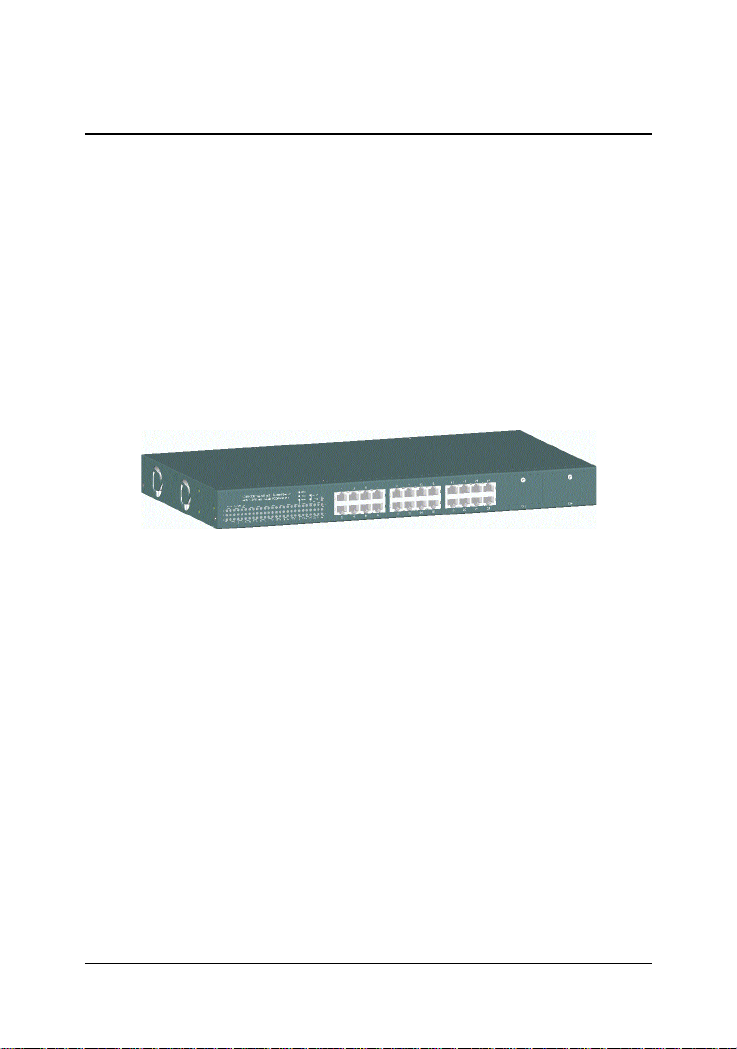
10/100 Managed Fast Ethernet Switch
with 100FX and Gigabit Connectivity
KS-2260
Optional 100FX Modules
Optional Gigabit Modules
Operation Manual
-1-
DOC.030425-KS2260-K
Page 2

(C) 2002 KTI Networks Inc. All rights reserved. No part of this documentation may be reproduced in any form or by any means or used to make
any directive work (such as translation or transformation) without permission from KTI Networks Inc.
KTI Networks Inc. reserves the right to revise this documentation and to
make changes in content from time to time without obligation on the part
of KTI Networks Inc. to provide notification of such revision or change.
For more information, contact:
United States KTI Networks Inc.
P .O. BOX 631008
Houston, T exas 77263-1008
Phone: 713-2663891
Fax: 713-2663893
E-mail: kti@ktinet.com
URL: http://www.ktinet.com/
International Fax: 886-2-26983873
E-mail: kti@ktinet.com.tw
URL: http://www.ktinet.com.tw/
-2-
Page 3

The information contained in this document is subject to change without prior
notice. Copyright (C) KTI. All Rights Reserved.
TRADEMARKS
Ethernet is a registered trademark of Xerox Corp.
WARNING:
This equipment has been tested and found to comply with the limits for a Class A
digital device, pursuant to Part 15 of the FCC Rules. These limits are designed to
provide reasonable protection against harmful interference when the equipment
is operated in a commercial environment. This equipment generates, uses, and
can radiate radio frequency energy and if not installed and used in accordance
with the instruction manual may cause harmful interference in which case the
user will be required to correct the interference at his own expense.
NOTICE:
(1 ) The changes or modifications not expressively approved by the party responsible for compliance could void the user's authority to operate the equipment.
(2 ) Shielded interface cables and AC power cord, if any, must be used in order
to comply with the emission limits.
CISPR A COMPLIANCE:
This device complies with EMC directive of the European Community and meets
or exceeds the following technical standard.
EN 55022 - Limits and Methods of Measurement of Radio Interference Characteristics of Information Technology Equipment. This device complies with CISPR
Class A.
WARNING: This is a Class A product. In a domestic environment this product may
cause radio interference in which case the user may be required to take adequate measures.
CE NOTICE
Marking by the symbol indicates compliance of this equipment to the EMC
directive of the European Community. Such marking is indicative that this equipment meets or exceeds the following technical standards:
EN 55022: Limits and Methods of Measurement of Radio Interference characteristics of Information Technology Equipment.
EN 50082/1:Generic Immunity Standard -Part 1: Domestic Commercial and Light
Industry.
EN 60555-2: Disturbances in supply systems caused by household appliances
and similar electrical equipment - Part 2: Harmonics.
-3-
Page 4

Table of Contents
1. Introduction ................................................................ 8
1.1 Introduction .................................................................................... 8
1.2 Features ........................................................................................ 9
1.3 Hardware Specifications ............................................................. 10
1.4 Software Specifications ............................................................... 1 2
1.4.1 Management Objects ............................................................... 1 3
1.4.2 SNMP Traps ............................................................................. 14
1.5 Function Descriptions ................................................................. 1 5
1.5.1 LACP Trunking Function .......................................................... 15
1.5.2 IP Multicast Function ................................................................ 17
1.5.3 MAC Address Filtering Function............................................... 19
1.5.4 Static MAC Address .................................................................. 20
1.5.5 Port Security.............................................................................. 20
1.5.6 VLAN Function .......................................................................... 21
1.5.6.1 Port-based VLAN ................................................................... 21
1.5.6.2 IEEE 802.1Q VLAN (Tag-based VLAN) ................................. 22
1.5.6.3 Protocol-based VLAN ............................................................ 2 3
1.5.7 Spanning Tree Protocol ........................................................... 2 3
1.5.8 Port Sniffer Function ................................................................. 25
1.5.9 QoS Priority Function ................................................................ 26
1.5.10 802.1X Port-Based Network Access Control ......................... 27
2. Installation and Management.................................. 30
2.1 Panel Description ........................................................................ 3 0
2.2 AC Power Supply ......................................................................... 30
2.3 Network Switched Ports .............................................................. 3 1
2.3.1 10/100TX Ports ......................................................................... 31
2.3.2 100FX Modules......................................................................... 3 2
2.3.3 Gigabit Ports and Modules ....................................................... 3 4
2.4 Rack Mounting............................................................................. 36
2.5 LED Indicators............................................................................. 37
2.6 Cooling Fans ............................................................................... 38
2.7 Management Setup ..................................................................... 3 9
2.7.1 Setup for Out-of-band (Console) Management ....................... 4 0
2.7.2 Setup for In-band Management ............................................... 4 1
2.7.3 Quick Guide to Configure Switch IP Address .......................... 4 1
3. Console and Telnet Operation ............................... 42
3.1 Main Menu ................................................................................... 44
-4-
Page 5

3.2 Switch Static Configuration ......................................................... 4 6
3.2.1 Port Configuration .................................................................... 4 7
3.3.2 Trunk Configuration .................................................................. 49
3.3.3 VLAN Configuration .................................................................. 5 0
3.3.3.1 VLAN Configure ..................................................................... 5 0
3.3.3.2 Create a VLAN Group ............................................................ 52
3.3.3.3 Edit / Delete a VLAN Group ................................................... 54
3.3.3.4 Groups Sorted Mode ............................................................. 55
3.3.4 Misc Configuration ................................................................... 56
3.3.4.1 MAC Age Interval.................................................................... 56
3.3.4.2 Broadcast Storm Filtering ..................................................... 5 7
3.3.4.3 Max Bridge Transmit Delay Bound........................................ 5 8
3.3.4.4 Port Security........................................................................... 59
3.3.4.5 Collision Retry Forever .......................................................... 60
3.3.4.6 Hash Algorithm ...................................................................... 6 0
3.3.5 Administration Configuration ................................................... 6 1
3.3.5.1 Change Username ............................................................... 6 1
3.3.5.2 Change Password ................................................................ 62
3.3.5.3 Device Information ................................................................ 62
3.3.5.4 IP Configuration..................................................................... 6 3
3.3.6 Port Sniffer Configuration ......................................................... 6 4
3.3.7 Priority Configuration ................................................................ 65
3.3.7.1 Static Priority .......................................................................... 66
3.3.7.2 802.1p Priority........................................................................ 67
3.3.8 MAC Address Configuration..................................................... 68
3.3.8.1 Static MAC Address ............................................................... 68
3.3.8.2 Filtering MAC Address........................................................... 70
3.4 Protocol Related Configuration ................................................... 7 1
3.4.1 STP ........................................................................................... 71
3.4.2 SNMP ........................................................................................ 75
3.4.2.1 System Options ..................................................................... 7 5
3.4.2.2 Community Strings ................................................................ 76
3.4.2.3 Trap Managers ...................................................................... 77
3.4.3 GVRP ........................................................................................ 78
3.4.4 IGMP ......................................................................................... 78
3.4.5 LACP......................................................................................... 79
3.4.5.1 Working Port Setting.............................................................. 79
3.4.5.2 State Activity ........................................................................... 80
3.4.5.3 LACP Status .......................................................................... 81
-5-
Page 6

3.4.6 802.1X....................................................................................... 81
3.4.6.1 Enable 802.1X Protocol......................................................... 8 2
3.4.6.2 802.1X System Configuration ............................................... 8 2
3.4.6.3 802.1X Per Port Configuration .............................................. 83
3.4.6.4 802.1X Misc. Configuration ................................................... 8 4
3.5 Status and Counters ................................................................... 85
3.5.1 Port Status ................................................................................ 86
3.5.2 Port Counters ........................................................................... 8 7
3.5.3 System Information .................................................................. 88
3.6 Reboot Switch ............................................................................. 8 9
3.6.1 Restart ...................................................................................... 8 9
3.6.2 Default ...................................................................................... 8 9
3.7 TFTP Update Firmware ............................................................... 9 0
3.7.1 TFTP Update Firmware ............................................................ 9 1
3.7.2 TFTP Restore Configuration .................................................... 92
3.7.3 TFTP Backup Configuration ..................................................... 9 3
4. SNMP Management ................................................. 94
4.1 Configuring SNMP Settings via Console Operation ................... 95
4.2 SNMP MIB-2 and Private MIB....................................................... 95
4.3 SNMP Traps ................................................................................ 98
5. Web Management .................................................... 99
5.1 Start Browser Software and Making Connection ...................... 10 0
5.2 Web Management Home Overview .......................................... 10 1
5.3 Port status ................................................................................. 10 2
5.4 Port Statistics............................................................................. 10 4
5.5 Administrator ............................................................................. 1 05
5.5.1 IP Address .............................................................................. 1 06
5.5.2 Switch Setting ......................................................................... 10 7
5.5.2.1 Basic Information ................................................................ 10 7
5.5.2.2 Module Info .......................................................................... 108
5.5.2.3 Advanced ............................................................................. 109
5.5.3 Console Port Information ....................................................... 112
5.5.4 Port Controls .......................................................................... 113
5.5.5 Trunking .................................................................................. 115
5.5.5.1 Aggregator settings ............................................................. 116
5.5.5.2 Aggregator Information ........................................................ 117
5.5.5.3 State Activity ......................................................................... 120
5.5.6 Forwarding and Filtering Database ....................................... 1 21
-6-
Page 7

5.5.6.1 IGMP Snooping.................................................................... 121
5.5.6.2 Static MAC Address ............................................................. 122
5.5.6.3 MAC Address Filtering......................................................... 1 23
5.5.7 VLAN configuration ................................................................. 124
5.5.7.1 Port-based VLAN ................................................................. 125
5.5.7.2 802.1Q VLAN ....................................................................... 127
5.5.8 Spanning Tree........................................................................ 1 31
5.5.9 Port Sniffer .............................................................................. 135
5.5.10 SNMP.................................................................................... 136
5.5.11 Security Manager .................................................................. 139
5.5.12 802.1X Configuration ........................................................... 1 40
5.5.12.1 802.1X PerPort Configuration ........................................... 14 2
5.5.12.2 802.1X Misc Configuration ................................................ 1 43
5.6 TFTP Update Firmware ............................................................. 14 4
5.7 Configuration Backup ................................................................ 14 6
5.7.1 TFTP Restore Configuration .................................................. 1 46
5.7.2 TFTP Backup Configuration ................................................... 1 47
5.8 Reset System ............................................................................ 14 8
5.9 Reboot ....................................................................................... 1 49
6. Update Firmware from Console ........................... 150
Appendix A: Factory Default Settings ...................... 151
-7-
Page 8
1. Introduction
1.1 Introduction
Driven by recent advances in desktop computing technology, toda y’s
network applications have increased in speed, power and the ability to
process information. To meet the demands of these more bandwidthintensive applications, this switch device provides significant increase
in performance for your Ethernet and Fast Ethernet network. The switch
comes with high number of 10/100 Fast Ethernet switched ports, each
capable of transferring information simultaneously at full wire speed to
control and allocate the network bandwidth. It also provides two Gigabit
Ethernet slots for migration to Gigabit network smoothly.
The key features of the switch units are:
• High Port-count and High Bandwidth
• 100FX connectivity
• Copper Gigabit connectivity
• Fiber Gigabit connectivity
• Network Management
-8-
Page 9

1.2 Features
• 19-inch rack mountable 24-Port 10/100 managed Fast Ethernet
switch with two Giga expansion port slots
• Provides two alternative 100Base-FX port slots for fiber connections
• Non-blocking and store-and-forward switch engine performs
forwarding and filtering at full wire speed.
• Supports diversified optional Giga port modules for selection
including 10/100/1000 copper type and fiber type
• Provides port control function for auto-negotiation, speed, duplex,
and flow control configuration
• Provides per-port Egress/Ingress data rate control function
• Provides 802.1X port-based network access control function
• Provides broadcast storm filtering function
• Provides 802.3ad port trunking function with up to 7 trunks
• Supports input-port-based, output-port-based, and input-outputpair-based Sniffer function
• Provides static MAC address and filtering MAC address configuration
• Provides ingress port security function
• Provides bridging delay bound control function
• Supports Ethernet frame length up to 1522 bytes
• Supports 802.3x flow control for full duplex mode and backpressure
flow control for half duplex mode
• Supports auto-aging with selectable inter-age time
• Supports port-based VLAN and 802.1Q tag-based VLAN
• Supports 802.1v protocol-based VLAN classification
• Supports port-based priority and 802.1p CoS with 2-level priorities
• Supports Spanning Tree Protocol
• Supports IP Multicasting and IGMP snooping
• Supports console/Telnet/SNMP/Web/Trap managements
-9-
Page 10

1.3 Hardware Specifications
10/100 Switched Ports Port 1 ~ 24, Total : 24 ports
802.3 10Base-T , 802.3u 100Base-TX compliant
Shielded RJ-45 with auto MDI-X function
Port 23, 24 Alternatives 100Base-FX connectivity
2 expansion module slots - Slot F23, F24
Giga Switched Ports 2 expansion Slots - Slot G1, G2
802.3z and 802.3ab compliant
Supports optional 10/100/1000 Copper module
Supports optional Giga Fiber modules
Port Control Function Port enable/disable
Auto-negotiation function
Speed,Duplex mode
Full duplex flow control function
Half duplex flow control function
Ingress data rate
Egress data rate
Port security (MAC learning function)
Flow Control Methods 802.3x pause frame based for full duplex
Backpressure for half duplex mode
Forwarding speed Max. 148,810 pps on 100M switched ports
Max. 1,488,100 pps on Gigabit switched ports
Trunking Function IEEE 802.3ad compliant
Per trunk mode : Static or LACP
Up to 7 trunk groups (trunk ports)
Each is composed of up to 4 ports
Port Sniffering One sniffer port (any one among 26 ports)
Up to 25 monitored ports
3 mode options - Tx / Rx / Tx+Rx traffic
MAC address aging time Control options - 300 ~ 765 seconds
MAC Address Table Size : 6K entries for
Auto-learned unicast addresses and
Static unicast/multicast addresses
Broadcast Storm Filtering Threshold options - 5%,10%, 15%,20%, 25%
Filtering MAC Address Destination address-based filtering
-10-
Page 11

Network Access Control 802.1X protocol support for all ports
Function Radius client configuration
Per port mode - Auto, Fu, Fa, No
QoS Function 2-level (High/Low) priority for Tx queues
Selectable Tx High/Low service ratio
Priority Decision Method First - Port-based priority
Second - 802.1p priority (Tag priority value)
VLAN Function Mode options if enabled -
Port-based VLAN
802.1Q T ag-based VLAN
Port-based VLAN Max. 26 VLAN groups
VLAN-tagging is ignored
No tag modification for tagged packets
802.1Q VLAN Max. 256 VLAN groups
- VLAN ID 2 ~ 4094
- Member port mode Outgoing : Tagged, Untagged
- GVRP 802.1Q complaint (GARP 802.1P complaint)
- Protocol classification 802.1v compliant
IP Multicasting Table 256 multicast address root entries
10/100 Port LED Display Link / Activity status
Speed status
Duplex / Collision status
Giga Port LED Display Link / Activity status
Duplex / Collision status
Console Port RS-232, DTE, DB9
Baud : 9600, N, 8, 1, 0, No flow control
Dimension 443mm (W) x 245mm (D) x 43mm (H)
Power Input Rating 100 ~ 240V AC, 50/60Hz, 50W
Input voltage range 90 ~ 264VAC
Input frequency 47 ~ 440Hz
Power Consumption 17W min. 26W max.
Environmental Operating temperature : 0 ~ 50oC
Storage temperature : -40 ~ 85oC
Certifications FCC Part 15 Class A
CE / CISPR Class A
-11-
Page 12

1.4 Software Specifications
Management interface
In-band SNMP over TCP/IP network
In-band W eb browser over TCP/IP network
In-band T elnet over TCP/IP network
Out-of-band via Console port
SNMP Traps over TCP/IP network
RFC & Protocols
IPv 4 IP version4 RFC791
TC P Transmission Control Protocol RFC793
UD P User Datagram Protocol RFC768
ARP Ehernet Address Resolution Protocol RFC826
ICMP Internet Control Message Protocol RFC792
SNM P SNMP agent v1 RFC1157
MIB-2 Standard MIB RFC1213
Traps Generic SNMP traps RFC1157
TFTP Trivial File Transfer Protocol RFC1350
Telnet Telnet protocol RFC854
HTTP HTTP server for web management RFC1945
GVRP GARP VLAN Registration Protocol 802.1Q
GARP Generic attribute registration protocol 802.1P
DHCP Dynamic Host Configuration Protocol RFC2131
IGMP Internet Group Management Protocol RFC2236
RMON MIB groups : Statistics, History, Alarm, Event RFC1271
Bridge Bridge MIB RFC1493
-12-
Page 13

1.4.1 Management Objects
List of management objects supported by console and T elnet interfaces :
Management Objects Console Telnet Web SNMP
Boot diagnostics Yes - - Login check Y es Yes Yes Port configuration Y es Yes Yes Trunk configuration (& LACP) Y es Yes Yes VLAN configuration Y es Yes Y es QoS Priority configuration Y es Yes Yes MAC address aging setting Yes Yes Yes Broadcast storm filtering setting Y es Yes Yes Max. bridge transmit delay bound Y es Yes Yes Low queue delay bound setting Y es Yes Yes Low queue delay time setting Yes Yes Yes Port security setting Y es Yes Yes Collision retry forever setting Y es Yes Yes Port Sniffer (Mirrowing) setting Y es Yes Yes IP configuration (TCP/IP) Y es Yes Yes Username, password change Yes Yes Yes SNMP community string settings Y es Yes Yes SNMP device information settings Yes Yes Yes Trap manager configuration Y es Yes Yes STP configuration Yes Yes Yes Static Mac address configuration Y es Yes Yes Filter Mac address configuration Yes Yes Yes GVRP setting Y es Y es Yes IGMP setting Y es Yes Yes -
802.1X configuration Y es Yes Y es System firmware update (TFTP) Yes Yes Y es System firmware update (1K modem) Yes - - Default configuration file download Yes Yes Yes Current configuration backup (TFTP) Y es Yes Yes Reboot switch with default settings Yes Yes Yes Reboot switch with current settings Yes Yes Yes -
-13-
Page 14

Management Objects Console Telnet Web SNMP
Port state - enable/disable Yes Yes Yes Yes
Port status - link, speed Y es Yes Yes Yes
Port static counters Yes Yes Yes Yes
Device Mac address information Yes Yes Yes Yes
System firmware version information Yes Y es Yes System hardware version information Y es Yes Yes System default configuration version Yes Yes Yes G1, G2 module information Y es Y es Y es Y es
F23, F24 module information Y es Yes Yes Yes
Cooling Fan1 Fan2 status Y es Yes Yes Yes
LACP status Yes Yes Yes IGMP snooping information - - Yes RFC 1213 MIB-2 objects - - - Yes
RFC 1493 Bridge MIB - - - Yes
RFC 1271 RMON MIB (group 1,2,3,9) - - - Yes
1.4.2 SNMP Traps
T rap Events
The table below lists the events the device will generate SNMP traps.
Generic: RFC1157 generic, Specific: EnterpriseSpecific
Type T rap Event
Generic Cold Start Device bootup
Generic Authentication SNMP authentication failure
Generic Port link change Port link down
Generic Port link change Port link recovery
Specific Fan1 failure Cooling Fan1 failure warning
Specific Fan1 failure Cooling Fan1 failure recovery
Specific Fan2 failure Cooling Fan2 failure warning
Specific Fan2 failure Cooling Fan2 failure recovery
-14-
Page 15

1.5 Function Descriptions
1.5.1 LACP Trunking Function
The switch provides a trunking function, which is compliant with 802.3ad
standard. 802.3ad is a specification from IEEE that allows us to bundle
several physical port links together to form one logical port , called a
trunk between two devices. It supports Link Aggregation Control Protocol (LACP).
IEEE 802.3ad trunking also allows redundant connections between devices to be combined for more aggregate bandwidth between devices
supporting LACP.
The LACP provides a standardized means for exchanging information
between two link partners on a link to allow their Link Aggregation Control instances to reach agreement on the identity of the Link Aggregation
Group to which the link belongs, move the link to that Link Aggregation
Group, and enable its transmission and reception functions in an orderly
manner.
The switch can support up to seven trunk groups, or called trunk ports
or trunks. Each group is a logic port and can have up to 4 physical port
members. A physical port can only belong to one trunk group. Each
trunk group can be set LACP disabled or enabled. The operations are:
LACP disabled
If one trunk group is LACP disabled, it becomes a local static trunk and
all member ports are forced to be work ports. The link aggregation is
formed and there is no LACP negotiation taking place. Maximal four
member ports are allowed.
LACP enabled
If one trunk group is LACP enabled, it is called LACP static trunk. Link
aggregation is formed through LACP negotiation between link partners.
Up to four ports can be selected as member ports for each trunk group.
However, the max. two ports, called work ports can be aggregated at the
-15-
Page 16

same time. Those member ports which are not work ports are standby to
become work port if any current work port fails to operate. This transition
takes about 30 seconds. Each member port can be set LACP Passive or
LACP active as described below:
LACP Passive : The port does not initiate the LACP negotiation, but it
does understand the LACP packet. It will reply to the received LACP
packet to eventually form the link aggregation if its link partner is
requesting to do so (in active state).
LACP Active : The port is willing to form an aggregate link, and initiate
the negotiation. The link aggregate will be formed if its link partner is
running in LACP active or passive mode.
There are only three valid combinations to run the LACP link aggregate
as follows:
• disabled to disabled state (forced link aggregate without LACP)
• active to active state
• active to passive state
Rules of trunking
1. Up to seven trunk groups (trunk ports) can be created.
2. Each trunk group can be composed of up to 4 member ports.
3. The member port can be one of Port 1 ~ Port 24 and G1 - G2 port.
4. One switched port only can belong to one trunk group.
5. If VLAN group exist, all members of one static trunk group must be
in same VLAN group.
6. LACP operation requires member ports in full-duplex mode.
7. In a static trunk group (LACP disabled), four work ports are aggre-
gated at the same time.
8. In an LACP trunk group, maximal two work ports can be aggregated
at the same time.
-16-
Page 17

1.5.2 IP Multicast Function
Internet Protocol (IP) multicast is a bandwidth-conserving technology
that reduces traffic by simultaneously delivering a single stream of information to thousands of corporate recipients and homes. Applications
that take advantage of multicast include video conference, corporate
communications, distance learning, and distribution of software, stock
quotes, and news.
IP Multicast delivers source traffic to multiple receivers without adding
any additional burden on the source or the receivers while using the least
network bandwidth of any competing technology. Multicast packets are
replicated in the network by the devices supporting multicast protocols
resulting in the most efficient delivery of data to multiple receivers possible.
Multicast is based on the concept of a group. An arbitrary group of
receivers expresses an interest in receiving a particular data stream. This
group does not have any physical or geographical boundaries - the
hosts can be located anywhere on the Internet. Hosts that are interested
in receiving data flowing to a particular group must join the group using
IGMP. Hosts must be a member of the group to receive the data stream.
IP Multicast address
IP Multicast addresses specify an arbitrary group of IP hosts that have
joined the group and want to receive traffic sent to this group. IP multicast
addresses range from 224.0.0.0 through 239.255.255.255. This address
range is only for the group address or destination address of IP multicast
traffic. The source address for multicast datagrams is always the unicast
source address.
-17-
Page 18

IGMP
Internet Group Management Protocol (IGMP) is used to dynamically
register individual hosts in a multicast group on a particular LAN. Hosts
identify group memberships by sending IGMP messages to their local
multicast router. Under IGMP, routers listen to IGMP messages and periodically send out queries to discover which groups are active or inactive
on a particular subnet.
RFC 2236 defines the specification for IGMP Version 2. There are four
types of IGMP messages:
• Membership query
• IGMP V ersion 1 membership report
• IGMP V ersion 2 membership report
• Leave group
Hosts send out IGMP membership reports corresponding to a particular
multicast group to indicate that they are interested in joining that group.
The router periodically sends out an IGMP membership query to verify
that at least one host on the subnet is still interested in receiving traffic
directed to that group. When there is no reply to three consecutive IGMP
membership queries, the router times out the group and stops forwarding
traffic directed toward that group.
With leave group message, the hosts can actively communicate to the
local multicast router their intention to leave the group. The router then
sends out a group-specific query and determines whether there are any
remaining hosts interested in receiving the traffic. If there are no replies,
the router times out the group and stops forwarding the traffic.
-18-
Page 19

IGMP Snooping
IGMP snooping requires the LAN switch to examine, or snoop, some
Layer 3 information in the IGMP packets sent between the hosts and the
router. When the switch hears the IGMP host report from a host for a
particular multicast group, the switch adds the host's port number to the
associated multicast table entry. When the switch hears the IGMP leave
group message from a host, it removes the host's port from the table
entry.
Multicast Forwarding
In multicast routing, the source is sending traffic to an arbitrary group of
hosts represented by a multicast group address. The multicast router
must determine which direction is upstream (toward the source) and
which direction (or directions) is downstream. If there are multiple downstream paths, the router replicates the packet and forwards the traffic
down the appropriate downstream paths - which is not necessarily all
paths.
The switch can support IP multicast if IGMP protocol is enabled. IGMP
snooping function and status is also provided. Each IP multicast address
is associated one Vlan ID and its member ports. The information is available from management interfaces.
1.5.3 MAC Address Filtering Function
MAC address filtering allows the switch to drop unwanted traffic. Incoming traffic is filtered based on the destination MAC addresses (DAs).
The unwanted destination addresses are called filter MAC addresses.
The switch provides management function that allows LAN administrator to maintain the filter MAC address table.
-19-
Page 20

1.5.4 Static MAC Address
The switch provides Static MAC Address setup function. The static
MAC addresses are the MAC addresses which are setup by LAN administrators and are not learned by the switch automatically.
The static addresses are stored and referred in switch MAC address
table permanently regardless of whether the MAC addresses are physically disconnected to the switch.
Applying this function with port security function allows LAN administrator to build a protection mechanism that let switch only serves granted
devices.
Static MAC address related settings:
Mac Address : Static Ethernet MAC address (12 digits)
Port num : The port number where the MAC address is located
Vlan ID : The associated Vlan ID to the address, if 802.1Q VLAN is enabled.
1.5.5 Port Security
A port in security mode does not learn any source MAC address (SA).
Only the incoming packets with SA existing in the switch static MAC
address table can be forwarded normally. Otherwise, the packets are
dropped. This features provides a protection mechanism to restrict the
devices link to the switch port. Only devices with valid MAC addresses
can be served by the switch.
-20-
Page 21

1.5.6 VLAN Function
Virtual LANs (VLANs) can be viewed as a group of devices on dif ferent
physical LAN segments which can communicate with each other as if
they were all on the same physical LAN segment. It can create a network
that is independent of physical location and group users into logical
workgroups. The benefits are:
• Confine broadcast traffic and Increased performance
• Improved manageability
• Network tuning and simplification of software configurations
• Physical topology independence
• Increased security options
The switch supports port-based, 802.1Q (T ag-based) and protocol-based
VLAN. In the default configuration, VLAN function is disabled.
1.5.6.1 Port-based VLAN
Up to 26 VLAN groups can be created. Each group has its own port
members. The member ports are selected among the physical ports on
the switch. Packets can go among only members in the same VLAN
group.
Required configurations:
• Maintain (Create/delete/modify) VLAN groups
• Manage the port members of each VLAN group
Note:
1. The ports which are not belonging to any group are treated as
belonging to another single VLAN.
2. A trunk group is treated as a physical port.
3. VLAN-tagging is ignored in port-based VLAN mode.
-21-
Page 22

1.5.6.2 IEEE 802.1Q VLAN (T ag-based VLAN)
Tag-based VLAN is an IEEE 802.1Q specification standard. Therefore, it
is possible to create a VLAN across devices from different venders. IEEE
802.1Q VLAN uses a technique to insert a tag into the Ethernet frames.
Tag contains a VLAN Identifier (VID) that indicates the VLAN numbers.
The switch can classify each received packet as belonging to one and
only one VLAN. If the received packet is VLAN-tagged, the packet is
classified as belonging to the VLAN specified in the VLAN tag header. If
the received packet is untagged, it is classified as belonging to the default VLAN configured for the ingress port.
Required configurations:
• Enable or disable GVRP support
• VLAN information including VID (2-4094) and name
• T agged member ports of each VLAN
• Outgoing tag mode for each member port
T ag - outgoing frames with VLAN-tagged
Untag - outgoing frames without VLAN-tagged
• PVID (Port VID, 1-255 for untagged incoming frames) for each port
• Ingress Rule 1 setting for each port : forward only packets with VID
matching configured PVID
• Ingress Rule 2 setting for each port : drop untagged frames
PVID : this feature is useful to accommodate the devices which do not
support tagging to participate in the VLAN.
GVRP - GARP [Generic Attribute Registration Protocol] VLAN Registration Protocol : GVRP allows automatic VLAN configuration between
the switch and nodes. If the switch is connected to a device with GVRP
enabled, you can send a GVRP request using the VID of a VLAN defined
on the switch, the switch will automatically add that device to the existing VLAN. (GVRP - 802.1Q complaint, GARP - 802.1P compliant)
-22-
Page 23

1.5.6.3 Protocol-based VLAN
In order for an end station to send packets to different VLANs, it itself
has to be either capable of tagging packets it sends with VLAN tags or
attached to a VLAN-aware bridge that is capable of classifying and tagging the packet with different VLAN ID based on not only default PVID
but also other information about the packet, such as the protocol. The
switch can support 802.1v compliant protocol-based VLAN classification by means of both built-in knowledge of layer 2 packet formats used
by selected popular protocols, such as Novell IPX and AppleTalk`s
EtherTalk, and others. Required configuration:
• Protocol setting for each VLAN group defined in 802.1Q VLAN mode
• If more than two VLAN groups are configured with same protocol
value, make sure the member ports of those groups are not overlaping.
Any incoming untagged packet is checked and classified according the
Protocol vs. VLAN mapping settings. If an associated VLAN group is
found, the packet is calssified and is inserted with VID tag of the group
VLAN ID instead of input port PVID.
1.5.7 Spanning Tree Protocol
Spanning-Tree Protocol (STP) is a link management protocol that provides path redundancy while preventing undesirable loops in the network. For an Ethernet network to function properly, only one active path
must exist between two stations. Multiple active paths between stations
cause loops in the network. If a loop exists in the network, you might
receive duplicate messages. When loops occur, some switches see stations on both sides of the switch. This condition confuses the forwarding algorithm and allows duplicate frames to be forwarded.
T o provide path redundancy, Spanning-Tree Protocol defines a tree that
spans all switches in an extended network. Spanning-Tree Protocol forces
certain redundant data paths into a standby (blocked) state. If one network segment in the Spanning-Tree Protocol becomes unreachable, or if
Spanning-Tree Protocol costs change, the spanning-tree algorithm
-23-
Page 24

re-configures the spanning-tree topology and reestablishes the link by
activating the standby path.
Spanning-Tree Protocol operation is transparent to end stations, which
are unaware whether they are connected to a single LAN segment or a
switched LAN of multiple segments.
STP related parameters
Priority : A value to identify the root bridge. The bridge with the lowest
value has the highest priority and is selected as the root.
MAC Address : The MAC address of the switch as a unique identifier
to the network.
Max Age : The number of seconds a bridge waits without receiving
Spanning Tree protocol configuration messages before attempting a
reconfiguration. Maximum Age Timer measures the age of the received
protocol information recorded for a port and ensures that this information is discarded when its age limit exceeds the value of the maximum age
parameter recorded by the switch. The time-out value for this timer is the
maximum age parameter of the switches.
Hello Time : The number of seconds between the transmission of Spanning Tree protocol configuration messages. It determines how often the
switch broadcasts its hello message to other switches.
Forward Delay Time : The number of seconds a port waits before changing from its Spanning Tree Protocol learning and listening states to the
forwarding state. Forward Delay Timer Monitors the time spent by a port
in the learning and listening states. The time-out value is the forward
delay parameter of
Spanning tree port states
Listening : Switches send messages to one another to establish the
network topology and the optimal paths to the different segments of
the network. Other data is not transmitted.
Blocking : The switch enters the Blocking State if a path with higher
priority is found to exist during the Listening State. Normal data is not
transmitted.
-24-
Page 25

Learning : The switch enters the Learning State if no path with a
higher priority is found during the Listening State. Learned entries are
entered in the Unicast Destination Forwarding T able. Normal data
is not transmitted.
Forwarding : The switch enters the Forwarding State after having been
in the Learning State for a predefined time period. Normal data is
transmitted.
Per port control settings
PathCost : Specifies the path cost for each port. The Spanning-Tree
Protocol uses port path costs to determine which port to select as a
forwarding port. You should assign lower numbers to ports attached to
faster media (such as full duplex), and higher numbers to ports attached
to slower media. The possible range is 1 to 65535. The recommended path
cost is 1000 divided by LAN speed in megabits per second.
Priority : Specify STP port priority for each port. The port (physical or
logical) with the lowest priority value has the highest priority and forwards the spanning-tree frames. The possible priority range is 0 through
255 (decimal). The default is 128. If all ports have the same priority value,
the lowest port number forwards the spanning-tree frames.
1.5.8 Port Sniffer Function
Port sniffer function is a method to duplicate all traffic occurred on the
specified monitored ports to the designated sniffer port. The traffic can
be configured for incoming packets only or outgoing packets only or
both. The control settings are:
Sniffer Mode : Specify the traffic type for monitoring
Options - Disable, Rx=incoming, Tx=outgoing, Both=Rx&Tx
Sniffer Port : Specify the port where performs monitoring
Monitored Port : Select the ports whose traffic will be duplicated to the
monitoring port. Press Space key for selection from the port member list.
-25-
Page 26

1.5.9 QoS Priority Function
This switch supports two priority levels, high and low, and provides two
priority functions:
1. Port-based Priority (Static priority)
2. 802.1p Priority (VLAN tagged priority)
Priority Classification Methods
Static priority is called port-based priority. The priority level of a receiving packet is determined by the configured priority of the input port
where the packet is received and the content of the packet is ignored.
Each port must be pre-configured with a priority level for incoming frames
or disabled setting.
802.1p Priority is a content-based priority method. If the receiving packet
is an 802.1Q VLAN tagged packet, the switch will check the 3-bit User
Priority value in TCI (Tag Control Information) field of packet tag data.
By this value, the packet is classified as high priority or low priority
according to 802.1p priority configuration. The map of priority values vs.
priority levels must be pre-configured.
The switch uses the following rules:
1. Applies Static Priority method first for tagged or untagged packets.
2. If port static priority is disabled, applies 802.1p Priority method.
3. Untagged packets are treated as low priority.
Outgoing Service Policy
The switch provides two options for outgoing service policy for high
priority packets and low priority packets.
1. High priority always first
2. Round robin method with specified [High : Low] ratio setting
This policy configuration can be set via the management interface.
-26-
Page 27
1.5.10 802.1X Port-Based Network Access Control
For some IEEE 802 LAN environments, it is desirable to restrict access to
the services offered by the LAN to those users and devices that are
permitted to make use of those services. IEEE 802.1X Port-based network
access control function provide a means of authenticating and authorizing devices attached to a LAN port that has point-to-point connection
characteristics, and of preventing access to that port in cases in which
the authentication and authorization process fails. The 802.1X standard
relies on the client to provide credentials in order to gain access to the
network. The credentials are not based on a hardware address. Instead,
they can be either a username/password combination or a certificate. The
credentials are not verified by the switch but are sent to a Remote Authentication Dial-In User Service (RADIUS) server, which maintains a
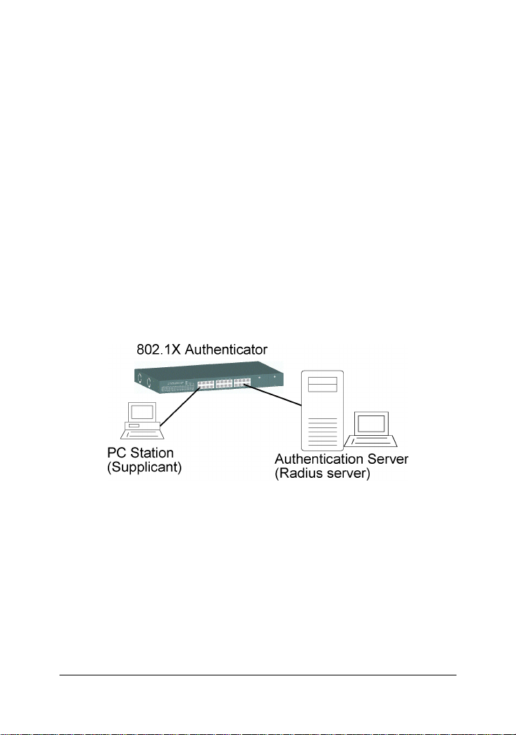
database of authentication information. 802.1X consists of three components for authentication exchange, which are as follows:
• An 802.1X authenticator: This is the port on the switch that has
services to offer to an end device, provided the device supplies the
proper credentials.
• An 802.1X supplicant: This is the end device; for example, a PC that
connects to a switch that is requesting to use the services (port) of the
device. The 802.1X supplicant must be able to respond to communicate.
• An 802.1X authentication server: This is a RADIUS server that exam-
ines the credentials provided to the authenticator from the supplicant and provides the authentication service. The authentication server is responsible for
letting the authenticator know if services should be granted.
-27-
Page 28

The 802.1X authenticator operates as a go-between with the supplicant
and the authentication server to provide services to the network. When
a switch is configured as an authenticator, the ports of the switch must
then be configured for authorization. In an authenticator-initiated port
authorization, a client is powered up or plugs into the port, and the
authenticator port sends an Extensible Authentication Protocol (EAP)
PDU to the supplicant requesting the identification of the supplicant. At
this point in the process, the port on the switch is connected from a
physical standpoint; however, the 802.1X process has not authorized the
port and no frames are passed from the port on the supplicant into the
switching engine. If the PC attached to the switch did not understand the
EAP PDU that it was receiving from the switch, it would not be able to
send an ID and the port would remain unauthorized. In this state, the port
would never pass any user traffic and would be as good as disabled. If
the client PC is running the 802.1X EAP , it would respond to the request
with its configured ID. (This could be a username/password combination
or a certificate.)
After the switch, the authenticator receives the ID from the PC (the supplicant). The switch then passes the ID information to an authentication
server (RADIUS server) that can verify the identification information.
The RADIUS server responds to the switch with either a success or
failure message. If the response is a success, the port will be authorized
and user traffic will be allowed to pass through the port like any switch
port connected to an access device. If the response is a failure, the port
will remain unauthorized and, therefore, unused. If there is no response
from the server, the port will also remain unauthorized and will not pass
any traffic.
The following configuration settings are required in the switch to make
802.1X function work:
-28-
Page 29

Enable 802.1X protocol
Radius client configuration Radius server IP : IP address of the Radius server
Shared key : en encryption key for use during authentication sessions
with the specified Radius server. It must match the key used on the
Radius server.
NAS identifier : identifier for this Radius client
Server port : the UDP destination port for authentication requests to the
specified Radius server
Accounting port : the UDP destination port for accounting requests to
the specified Radius server
Per-port 802.1X mode setting:
Auto (Au) - The port is set to the Authorized or Unauthorized state in
accordance with the outcome of an authentication exchange between the
Supplicant and the Authentication Server.
Forced Authorized (Fa) - The port is forced to be in authorized state.
Forced Unauthorized (Fu) - The port is forced to be in unauthorized state.
None (No) - The port is not necessary authorized.
Misc. configuration:
quietPeriod - the period during which the port does not try to acquire a
supplicant
txPeriod - the period the port waits to retransmit the NEXT EAPOL PDU
during an authentication session
suppTimeout - the period of time the switch waits for a supplicant response toan EAP request
serverTimeout - the period of time the switch waits for a server response
to an authentication request
reAuthMax - the number of authentication attempts that must time-out
before authentication fails and the authentication session ends.
reAuthPeriod - the period of time after which the connected radius clients must be re-authenticated
-29-
Page 30
2. Installation and Management
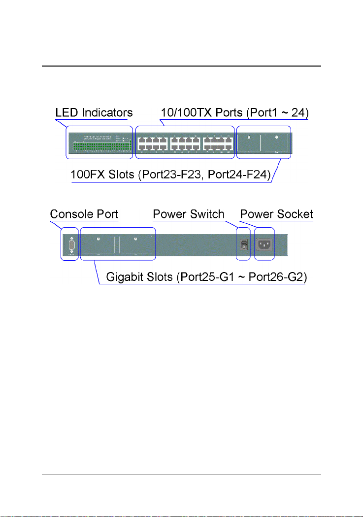
2.1 Panel Description
2.2 AC Power Supply
One AC power cord which meets the specification of your country of
origin was supplied with the switch unit. Before installing AC power cord
to the switch, make sure the AC power switch is in OFF position and the
AC power to the power cord is turned off. The switch supports wide
range of AC power input specifications as follows:
Power Rating : 100 ~ 240VAC, 50/60Hz, 50W
Voltage Range : 90 ~ 260VAC
Frequency : 47 ~ 440 Hz
Inrush Current : 24A@230V
Minimal Consumption : 17W
Maximal Consumption : 26W
-30-
Page 31

2.3 Network Switched Ports
The switch provides three types of switched ports as follows:
Port Number Label Specifications Port T ype Modules
Port 1 - 22 1 - 22 Fixed RJ-45 10/100TX No
Port 23 - 24 23 - 24 Fixed RJ-45 10/100TX No
F23 - F24 Module slot 100FX Optional
Port 25-26 G 1 - G2 Module slot Gigabit Optional
2.3.1 10/100TX Ports
The 10/100TX ports supports the following connection types and distances:
Speed Compliance Cables Distance
10Mbps IEEE 802.3 10BASE-T Cat. 3, 4, 5, 5e 100 meters
100Mbps IEEE 802.3u 100BASE-TX Cat. 5, 5e 100 meters
The ports can be configured to one of the following operating modes:
Auto mode : The port is auto-negotiation enabled and uses the speed
and duplex settings as the highest port capability for negotiation with its
auto-negotiation capable link partner.
Nway_Forced mode : The port is auto-negotiation enabled and uses the
speed and duplex settings as the only port capability for negotiation with
its auto-negotiation capable link partner.
Forced mode : The port is auto-negotiation disabled and uses the speed
and duplex settings as the connection configuration.
-31-
Page 32

2.3.2 100FX Modules
Port 23 and Port 24 also provide optional fiber connectivity. The following installation rules should be applied:
100FX Module Installation Working Connectors
F23 Slot F24 Slot Port 23 Port 24
None None P23 RJ-45 P24 RJ-45
Installed None F23 module P24 RJ-45 can not be used
None Installed P23 RJ-45 F24 module
Installed Installed F23 module F24 module
This figure illustrates an example of 100FX module. Every module has
one jumper JP1 as shown. JP1 can be used to disable the module even the
module is installed in the switch unit.
JP1 setting
O N - Short the jumper to enable the module
O N - Open the jumper to enable the module
-32-
Page 33

The following 100FX modules are supported by F23 and F24 slots:
Part Number Connector Cable Distance
2260-FMT Duplex ST MMF* 2 km
2260-FMC Duplex SC MMF 2 k m
2260-FJM MT-RJ MMF 2 km
2260-FVM VF-45 MMF 2 km
2260-FSA2 Duplex SC SMF* 20 km
Note: * MMF - Multimode Fiber cable 50/125, 62.5/125 mm
* SMF - Single Mode Fiber cable 8.7/125, 9/125, 10/125 mm
Specifications
IEEE 802.3u 100BASE-FX compliant, Fixed 100Mbps, Fixed Full duplex
Optical Specifications
Part Number Wavelength Output Power Input Optical Power
2260-FMT 1310nm -19 ~ -14dBm -31dBm min. -14dBm max.
2260-FMC 1310nm -19 ~ -14dBm -31dBm min. -14dBm max.
2260-FJM 1310nm -20 ~ -14dBm -31dBm min. -14dBm max.
2260-FVM 1310nm -20.5 ~ -15dBm -33dBm typ. sensitivity
2260-FSA2 1310nm -18 ~ -7dBm -32dBm max. sensitivity
Installation steps:
1. Turn the power to the switch off.
2. Set JP1.
3. Insert the 100FX modules and screw the modules securely.
4. Turn the power to the switch on.
-33-
Page 34

2.3.3 Gigabit Ports and Modules
Port 25 and Port 26, labeled G1 and G2 respectively, support the following
Gigabit modules:
Part Number Connector Cable Distance
2260-GT RJ-45 Cat.5e 100m
2260-SXC Duplex SC MMF 62.5/125mm 220m
MMF 50/125mm 500m
2260-SXL Duplex LC MMF 62.5/125mm 220m
MMF 50/125mm 500m
226 0-L XC Duplex SC MMF 62.5/125mm 550m
MMF 50/125mm 550m
SMF 9/125mm 10 km
-34-
Page 35

Specifications
Part Number Compliance Speed Duplex
2260-GT IEEE 802.3ab 1000BASE-T 1000Mbps Half / Full
IEEE 802.3u 100BASE-TX 100Mbps Half / Full
IEEE 802.3 10BASE-T 10Mbps Half / Full
Auto-negotiation function
MDI-X RJ45
2260-SXC IEEE 802.3z 1000BASE-SX 1000Mbps Full
2260-SXL IEEE 802.3z 1000BASE-SX 1000Mbps Full
2260- LXC IEEE 802.3z 1000BASE-LX 1000Mbps Full
Optical Specifications
Part Number Wavelength Output Power Input Optical Power
2260-SXC 850nm -9.5 ~ -4dBm -17 (sensitivity) ~ 0 dBm
2260-SXL 850nm -9.5 ~ -4dBm -17 (sensitivity) ~ 0 dBm
2260-LXC 1310nm -11 ~ -3dBm -22 (sensitivity) ~ -3 dBm
Installation steps:
1. Turn the power to the switch off.
2. Insert the Gigabit modules and screw the modules securely.
3. Turn the power to the switch on.
-35-
Page 36

2.4 Rack Mounting
T wo 19-inch rack mounting brackets are supplied with the switch for 19inch rack mounting.
The steps to mount the switch onto a 19-inch rack are:
1. Turn the power to the switch off.
2. Install two brackets with supplied screws onto the switch as shown
in above figure:
2. Mount the switch onto 19-inch rack with rack screws securely.
3. Turn the power to the switch on.
-36-
Page 37

2.5 LED Indicators
LED Name State Interpretation
System LEDs
P(Power) On Power is supplied to the unit.
Off No power is supplied to the unit.
C(Console) On Tx activities
Off No Tx or Rx
D(Diag) Blink Diagnostic and initialization in process
On Diagnostic and initialization completed
Port 1 ~ Port 24 LEDs
100/10 On Port speed is 100Mbps.
Off Port speed is 10Mbps.
Link/Act. On Port link up
Off Port link down
Blink Port Tx/Rx activities
FDX/Col. On Port is in full duplex.
Off Port is in half duplex.
Blink Collisions
Port 25 (G1), Port 26 (G2) LEDs
Link/Act. On Port link up
Off Port link down
Blink Port Tx/Rx activities
FDX/Col. On Port is in full duplex.
Off Port is in half duplex.
Blink Collisions
-37-
Page 38

2.6 Cooling Fans
The switch is equipped with two cooling fans. Both fans are featured
with failure detection function. When the fan operation speed is below
the specification, it is detected as a failure. The fan status can be monitored via management functions. One fan failure trap is also issued when
fan failure event occurs.
Important :
Do not operate the switch unit when a fan failure is detected. Without
normal operation of the cooling fans, the switch unit might not operate
properly or even might be damaged due to not enough ventilation. Return the defective unit to the dealer where it was purchased.
-38-
Page 39

2.7 Management Setup
The managed switch is featured with management functions and can be
managed by using the following methods:
• Direct console connection over an RS-232 cable
• T elnet software over TCP/IP network
• SNMP manager software over TCP/IP network
• W eb browser software from Internet or Intranet over TCP/IP network
• SNMP trap hosts from Internet or Intranet over TCP/IP network
The following figure illustrates a management model diagram:
-39-
Page 40

2.7.1 Setup for Out-of-band (Console) Management
Before doing any in-band management, it is necessary to perform console operation for configuring IP and SNMP related settings for the first
time the switch is received for installation. Any PC running Windows 95/
98/ or NT can be used as a console via COM port. Windows Hyper
Terminal program is an ideal and the most popular software for such
console terminal operations.
To setup console operation, the steps are:
1. Find a proper RS-232 cable for the connection to a console terminal.
If your are using PC as a terminal, make sure the cable pin assignments comply to the following requirement.
Console port 9-pin PC COM port
Pin2 RXD -------------------------------- 3
3 TXD -------------------------------- 2
4 DTR -------------------------------- 6
5 GND -------------------------------- 5
6 DSR -------------------------------- 4
2. Connect one end to the console port and connect the other end to
the PC COM port.
3. Configure your PC COM port setting to match the RS-232 settings of
the console port and start your terminal software.
Factory default settings of the Console port
Baud rate : 9600, N, 8, 1, 0
Flow control : disabled
4. Turn the switch unit power on.
5. Press <Enter> key several times in your terminal software until a
login prompt comes up. It means the connection is proper.
The console port does not support modem connection. Refer to Chapter
3 for more information about Console management.
-40-
Page 41

2.7.2 Setup for In-band Management
To perform an in-band management, it is necessary to connect the system to your TCP/IP network. The steps are:
1. Configure IP and SNMP related settings to the device using direct
console management when you receive it first time for the installation.
2. Find a proper straight-through Category 5 UTP cable (maximal length
100 meters) for the connection.
3. Connect one end of the UTP cable to the UTP port of the media
converter and connect the other end to a network device, such as a
switching hub, in your TCP/IP network.
4. Start your in-band management operations. For different manage-
ment methods, refer to:
• Chapter 3 for Console and Telnet management
• Chapter 4 for SNMP management
• Chapter 5 for W eb management
2.7.3 Quick Guide to Configure Switch IP Address
This section provides a quick instruction to configure a new IP address
via Console port for the switch received for the first time. The steps are:
1. Set up console connection as described in section 2.7.1.
2. Login with default username= admin and password=123.
3. Menu selections to enter IP configuration as follows:
Main Menu
-> Switch Static Configuration
-> Administration Configuration
-> IP Configuration
-41-
Page 42

3. Console and Telnet Operation
This chapter describes the detailed console operation. It can be applied
to either out-of-band console management or in-band Telnet management. Refer to Chapter 2 for installation details.
Cold Start
When the power to the switch is turned on, the device start initialization
and self-test process. The self-test messages are displayed as follows if
a console connection is established successfully.:
Power-on Self-test Console message
---------------------------------------------
$$$ Switch LOADER Checksum O.K !!!
$$$ Press any key to start Xmodem receiver:
$$$ Switch IMAGE Checksum ...... O.K !!!
$$$ Loading IMAGE ...............................
$$$ Switch Power On Self Test...
$$$ CPU(arm7) Sdram Test Start..
++ Memory Test (Long) .... O.K !!!
++ Memory Test (Short) ... O.K !!!
++ Memory Test (Byte) .... O.K !!!
$$$ CPU(arm7) Sdram Test O.K !!!
$$$ Switch Register R/W Test ...O.K !!!
$$$ Phy Register R/W Test ...O.K !!!
$$$ Embedded Sram Built In Self Test ...O.K !!!
$$$ Switch Data Area Checksum ...O.K !!!
$$$ Detect Module Card... O.K !!!
$$$ Switch Engine Initialize...O.K !!!
$$$ Trunk Initialize...O.K !!!
$$$ Port Initialize...O.K !!!
$$$ BwCtrl Initialize...O.K !!!
$$$ Forwarding Initialize...O.K !!!
$$$ Vlan Initialize...O.K !!!
---------------------------------------------
Both console management and T elnet management are same in operation
starting from login prompt.
-42-
Page 43

Direct Console Management
When you can see the self-test messages shown on screen properly, you
can press <Enter> key to start console login operation. Go to Login
Prompt section in next page directly .
T elnet Management
Use Telnet software to perform the management operation. The most
convenient solution is using the built-in Telnet function in a Windows
95/98/ or NT PC. Enter into DOS window and invoke T elnet command :
>telnet xxx.xxx.xxx.xxx
to connect to the device. The specified xxx.xxx.xxx.xxx is the IP address of
the device. Factory default IP address is 192.168.0.2.
A welcome message and login prompt are displayed if the connection is
established properly.
Login Prompt
The following figure illustrates the login screen:
----------------------------------------------------
User Interface
Managed 24 + 2G Switch
login:xxxx
password:xxxx
----------------------------------------------------
Username : admin
Factory default Password : 123
For security reason, the device supports a function to change the password in setup menu. It is recommended to change the default password
immediately after a successful login.
-43-
Page 44

3.1 Main Menu
When login successfully, the main menu is shown as follows:
---------------------------------------------
Main Menu
Switch Static Configuration
Protocol Related Configuration
Status and Counters
Reboot Switch
TFTP Update Firmware
Logout
Configure the switch.
Arrow/TAB/BKSPC = Move Item Enter= Select Item
---------------------------------------------
Function description of the selected item:
Switch Static Configuration : Configure the switch related settings
Protocol Related Configuration : Configure the protocol parameters
Status and Counters : Show the status of the switch
Reboot Switch : Reboot the system or restore factory default configuration
TFTP Update Firmware : Use tftp to download firmware image
Logout : Exit the menu line program.
-44-
Page 45

The following operation convention is commonly used for later configuration pages:
Action menu:
<Quit> Exit configuration
<Edit> Edit each configuration value
<Save> Save all configured values
<Previous Page> Browse previous configuration page
<Next Page> Browse next configuration page
Control keys for action menu:
[T ab] ke y Move to next item
[Backspace] key Move to previous item
[Enter] key Confirm selection
Control keys used for <Edit> operation:
[T ab] ke y Move to next item
[Backspace] key Move to previous item
[Space] key Change configuration option
[Ctrl+A] key Quit from <Edit> operation, back to action menu
-45-
Page 46

3.2 Switch Static Configuration
[Switch Static Configuration] menu is shown as follows:
----------------------------------------------------
Managed 24+2G Switch : Switch Configuration
Port Configuration
Trunk Configuration
VLAN Configuration
Misc Configuration
Administration Configuration
Port Sniffer Configuration
Priority Configuration
MAC Address Configuration
Main Menu
Display or change port configuration
----------------------------------------------------
-46-
Page 47

3.2.1 Port Configuration
The following page illustrates Port 1 ~ Port 8 configuration example:
-------------------------------------------------------------------------
Managed 24+2G Switch : Port Configuration
InRate OutRate FlowControl
Port Type (100K) (100K) Enable Auto Spd/Dpx Full Half
----------------------------------------------------------------- PORT1 100TX 0 0 Yes AUTO 100 FULL On On
PORT2 100TX 0 0 Yes AUTO 100 FULL On On
PORT3 100TX 0 0 Yes AUTO 100 FULL On On
PORT4 100TX 0 0 Yes AUTO 100 FULL On On
PORT5 100TX 0 0 Yes AUTO 100 FULL On On
PORT6 100TX 0 0 Yes AUTO 100 FULL On On
PORT7 100TX 0 0 Yes AUTO 100 FULL On On
PORT8 100TX 0 0 Yes AUTO 100 FULL On On
action->
------------------------------------------------------------------
Tab=Next Item BackSpace=Previous Item Quit=Previous Menu Enter= Select Item
-------------------------------------------------------------------------
<Quit> <Edit> <Save> <Previous Page> <Next Page>
-47-
Page 48

Port : Port number
Display names - PORT1 - POR T24, G1 - G2
Type : Port type
Display names - 100Tx, 100FX, 1000T , 1000FX
InRate : Input (Ingress) rate control setting, 100Kbytes per unit.
Options - 0 = disable rate control, 1 ~ 1000 valid rate value
OutRate : Output (Egress) rate control setting, 100Kbytes per unit
Options - 0 = disable rate control, 1 ~ 1000 valid rate value
Enable : Port function enable / disabled control setting
Options - Y es=Enable, No=Disable
Auto : Port auto negotiation mode control setting
Options - Auto, Nway_Force, Force
Spd/Dpx : Port speed and duplex configuration control setting
Flow Control / Full : Full duplex flow control (Pause frame) setting
Options - On=Enable, Off=Disable
Flow Control / Half : Half duplex flow control (Backpressure) setting
Options - On=Enable, Off=Disable
Note:
1. Port 25 (G1 slot) and Port 26 (G2 slot) are not displayed if no module
is installed in the slot.
2. Input (Ingress) Rate control function works only when the port and
its link partner operate with flow control enabled.
-48-
Page 49

3.3.2 Trunk Configuration
Trunk configuration example page
-------------------------------------------------------------------------
Managed 24+2G Switch : Trunk Configuration
01 02 03 04 05 06 07 08 09 10 11 12 13 14 15 16 17 18 19 20 21 22 23 24 G1 G2
1 V V V V - - - - - - - - - - - - - - - - - - - - - 2 - - - - V V V V - - - - - - - - - - - - - - - - - 3 - - - - - - - - - - - - - - - - - - - - - - - - - 4 - - - - - - - - - - - - - - - - - - - - - - - - - 5 - - - - - - - - - - - - - - - - - - - - - - - - - 6 - - - - - - - - - - - - - - - - - - - - - - - - - 7 - - - - - - - - - - - - - - - - - - - - - - - - - -
TRK1 STATIC
TRK2 LACP
TRK3 DISABLE
TRK4 DISABLE
TRK5 DISABLE
TRK6 DISABLE
TRK7 DISABLE
action-> <Edit> <Save>
------------------------------------------------------------------
Tab=Next Item BackSpace=Previous Item Quit=Previous Menu Enter= Select Item
-------------------------------------------------------------------------
<Quit>
Select up to four member ports for each enabled trunk group.
Trunk port mode control settings for each trunk group:
DISABLE The group is disabled.
STATIC Normal trunk
LACP This trunk group is LACP enabled.
Refer to Chapter 1 for description of LACP trunking function.
-49-
Page 50

3.3.3 VLAN Configuration
----------------------------------------------------
Managed 24+2G Switch : VLAN Configuration
VLAN Configure
Create a VLAN Group
Edit/Delete a VLAN Group
Group Sorted Mode
Previous Menu
Configure the VLAN pvid and ingress.egress rules
Tab=Next Item BackSpace=Previous Item Quit=Previous Menu Enter= Select Item
-------------------------------------------------------------------------
3.3.3.1 VLAN Configure
----------------------------------------------------
Managed 24+2G Switch : VLAN Support Configuration
VLAN Mode : PortBased
action-> <Quit> <Edit> <Save> <Previous Page> <Next Page>
------------------------------------------------------------------
Tab=Next Item BackSpace=Previous Item Quit=Previous Menu Enter= Select Item
-------------------------------------------------------------------------
VLAN Mode control setting:
PortBased Port-based VLAN is used.
802.1Q IEEE 802.1Q VLAN is used
Disabled VLAN function is disabled.
Note: When VLAN mode is changed, the switch must be reboot to make
the change effective.
-50-
Page 51

If 802.1Q mode is selected, some additional settings are required as follows:
----------------------------------------------------
Managed 24+2G Switch : VLAN Support Configuration
VLAN Mode : 802.1Q
IngressFilter1 IngressFilter2
Port PVID NonMember Drop Untagged Drop
----------------------------------------------------------------- PORT1 1 FORWARD DROP
PORT2 3 FORWARD FORWARD
PORT3 1 DROP FORWARD
PORT4 1 DROP FORWARD
PORT5 1 DROP FORWARD
PORT6 1 DROP FORWARD
PORT7 1 DROP FORWARD
PORT8 1 DROP FORWARD
action->
------------------------------------------------------------------
Tab=Next Item BackSpace=Previous Item Quit=Previous Menu Enter= Select Item
-------------------------------------------------------------------------
<Quit> <Edit> <Save> <Previous Page> <Next Page>
Per port control settings:
PVID : Port VID
Optional values - 1 ~ 255
Ingress Filter / NonMember Drop: Drop or forward input VLAN tagged
frames whose VID does not match PVID associated to the input port.
This rule is applied only when input port is not the member port of the
associated VLAN group. Setting options - DROP , FOR WARD
Ingress Filter / UnT agged Drop: Drop or forward input untagged frames
Options - DROP , FOR W ARD
-51-
Page 52

3.3.3.2 Create a VLAN Group
Create a Port-based VLAN group
----------------------------------------------------
Add a VLAN Group
VLAN Name: [Vlan2 ] Grp ID:[2 ](1~4094)
Port Member
---------------------- PORT1 Member
PORT2 Member
PORT3 No
PORT4 No
PORT5 No
PORT6 No
PORT7 No
PORT8 No
action-> <Quit> <Edit> <Save> <Previous Page> <Next Page>
------------------------------------------------------------------
Tab=Next Item BackSpace=Previous Item Quit=Previous Menu Enter= Select Item
-------------------------------------------------------------------------
New Port-based VLAN group settings:
VLAN name :Give a name to this new VLAN
Grp ID : Give an ID number to this new VLAN (V alid values 1-4094)
Member : The port specified is the member to this new VLAN.
Note:
If trunk groups exist, they are also listed after PORT26 and labeled TRK1,
TRK2 .. and etc.. They also can be configured as VLAN member.
-52-
Page 53

Create an 802.1Q VLAN
----------------------------------------------------
Add a VLAN Group
VLAN Name: [
Protocol VLAN : None
Port Member
----------------------PORT1 UnTagged
PORT2 Tagged
PORT3 UnTagged
PORT4 No
PORT5 No
PORT6 No
PORT7 No
PORT8 No
Vlan2 ] VLAN ID:[2 ](1~4094)
action->
------------------------------------------------------------------
Tab=Next Item BackSpace=Previous Item Quit=Previous Menu Enter= Select Item
-------------------------------------------------------------------------
<Quit> <Edit> <Save> <Previous Page> <Next Page>
New 802.1Q VLAN settings:
VLAN name :Give a name to this new VLAN
VLAN ID : Give a VID to this new VLAN (V alid values: 2-4094)
Protocol VLAN : Select protocol type.
Options - None
IP, ARP, AppleT alk / NetBIOS, Novell IPX,
Banyan Vines C4 / Novell IPX (raw Ethernet)
Banyan V ines C5 / Spanning Tree Protocol BPDU
Banyan Vines AD / Null SAP, DECnet MOP 01
DECnet MOP 02, DECnet DPR, DECnet LA T
DECnet LA VC, IBM SN, X.75 Internet, X.25 Layer 3
-53-
Page 54

Member : Give a member setting, Options -
UnT agged : the specified port is a member port and outgoing frames
are not tagged.
Tagged : the specified port is a member port and outgoing frames
are tagged.
No : the specified port is not a member port
Note:
If more than two VLAN groups are configured with same protocol value,
make sure the member ports of those groups are not overlapping.
3.3.3.3 Edit / Delete a VLAN Group
Example to select one VLAN group for editing or deleting:
----------------------------------------------------
NAME VID NAME VID
------------- ------------ DEFAULT 1
Vlan2 2
action-> <Quit> <Edit> <Delete> <Previous Page> <Next Page>
------------------------------------------------------------------
Tab=Next Item BackSpace=Previous Item Quit=Previous Menu Enter= Select Item
-------------------------------------------------------------------------
Choose the VLAN group that you want to edit or delete and then press enter.
Note:
The VLAN Name and VLAN ID cannot be modified. Default VLAN VID=1
can not be deleted.
-54-
Page 55

Example to edit Vlan2 group:
----------------------------------------------------
Edit a VLAN Group
VLAN Name: [
Protocol VLAN : AppleTalk/NetBIOS
Port Member
----------------------PORT1 UnTagged
PORT2 Tagged
PORT3 UnTagged
PORT4 No
PORT5 No
PORT6 No
PORT7 No
PORT8 No
Vlan2 ] VLAN ID:[2 ](1~4094)
action->
------------------------------------------------------------------
Tab=Next Item BackSpace=Previous Item Quit=Previous Menu Enter= Select Item
-------------------------------------------------------------------------
<Quit> <Edit> <Save> <Previous Page> <Next Page>
3.3.3.4 Groups Sorted Mode
Set sorted mode for VLAN groups shown in Edit/Delete a VLAN group
page as follows and the options are Sorted_by_Name and Sorted_by_VID:
----------------------------------------------------
Managed 24+2G Switch : Group Sorted Selection
Group Sorted : Sorted_by_Name
action-> <Edit> <Save> <Quit>
------------------------------------------------------------------
Tab=Next Item BackSpace=Previous Item Quit=Previous Menu Enter= Select Item
-------------------------------------------------------------------------
-55-
Page 56

3.3.4 Misc Configuration
----------------------------------------------------
Managed 24+2G Switch : Misc Configuration
MAC Age Interval
Broadcast Storm Filtering
Max bridge transmit delay bound
Port Security
Collision Retry Forever
Hash Algorithm
Previous Menu
Configure the MAC aging time
Tab=Next Item BackSpace=Previous Item Quit=Previous Menu Enter= Select Item
-------------------------------------------------------------------------
3.3.4.1 MAC Age Interval
----------------------------------------------------
Managed 24+2G Switch : MAC Aging Time
MAC Age Interval (sec) [300] : 300
(disable:0, valid value: 300-765)
action-> <Edit> <Save> <Quit>
------------------------------------------------------------------
Tab=Next Item BackSpace=Previous Item Quit=Previous Menu Enter= Select Item
-------------------------------------------------------------------------
Set the time interval that an inactive MAC address remained in the switch
MAC address table. Options - 0=Disable, 300=Default, 300 ~ 765 seconds
-56-
Page 57

3.3.4.2 Broadcast Storm Filtering
----------------------------------------------------
Managed 24+2G Switch : Broadcast Storm Filter Mode
Broadcast Storm Filter Mode : NO
action-> <Edit> <Save> <Quit>
------------------------------------------------------------------
Tab=Next Item BackSpace=Previous Item Quit=Previous Menu Enter= Select Item
-------------------------------------------------------------------------
Broadcast storm protection control setting:
Threshold options - NO, 5%,10%,15%,20%,25%
The threshold is the percentage of the total packet buffer occupied by
queued broadcast packets. Upon reaching the threshold, broadcast strom
filtering mechanism is activated and further incoming broadcast packets
are dropped.
-57-
Page 58

3.3.4.3 Max Bridge Transmit Delay Bound
---------------------------------------------------Managed 24+2G Switch : Max Bridge Transmit Delay Bound
Max bridge transmit delay bound : OFF
Low Queue Delay Bound : ENABLE
Low Queue Max Delay Time : 255 (2ms/unit)
action-> <Edit> <Save> <Quit>
-------------------------------------------------------------------------
Max bridge transmit delay bound: Limit the packets queuing time in switch.
If enabled and queuing time expired, the queued packets will be dropped.
Options - OFF (default), 1sec, 2sec, 4sec
Low Queue Delay Bound: Limit the low priority packets queuing time in
switch. If enabled and queuing time expired, the low priority packets
queued in switch will be sent.
Low Queue Max Delay Time: The maximal time that a low priority packet
will be queued in switch.
Options - 1~255, 255=default, (2ms/unit)
Note:
Make sure Max bridge transit delay bound control is enabled when Low
Queue Delay Bound control is set to ENABLE.
-58-
Page 59

3.3.4.4 Port Security
----------------------------------------------------
Managed 24+2G Switch : Port Security
Port Enable Security
(disable MAC learning)
----------------------------------------------------------------- PORT1 Enabled
PORT2 Enabled
PORT3 Enabled
PORT4 Disabled
PORT5 Disabled
PORT6 Disabled
PORT7 Disabled
PORT8 Disabled
action->
-------------------------------------------------------------------------
<Quit> <Edit> <Save> <Previous Page> <Next Page>
A port in security mode will be locked and disabled to perform further
MAC address learning. Only the incoming packets with source MAC
address already existing in the switch MAC address table can be forwarded normally. Otherwise, the packets are dropped.
Options - Enabled, Disabled
For specific security application, user can disable the port from learning
any new MAC addresses, then use the static MAC addresses operation
to define a list of MAC addresses that are allowed to pass through the
secure port.
-59-
Page 60

3.3.4.5 Collision Retry Forever
----------------------------------------------------
Managed 24+2G Switch : Collision Retry Forever
Collision Retry Forever : Enabled
action-> <Edit> <Save> <Quit>
----------------------------------------------------
Collision Retry control setting for half duplex mode :
Options - Enabled = collision retry forever
Disabled = collision retry 48 times then drop frames
3.3.4.6 Hash Algorithm
----------------------------------------------------
Managed 24+2G Switch : Hash Algorithm
Hash Algorithm : Enabled
action-> <Edit> <Save> <Quit>
----------------------------------------------------
Hash method for MAC address table :
Options - CRC-Hash = Use CRC hash for table index
DirectMap = Use direct map for table index
Note:
It is recommended not to change the default value.
-60-
Page 61

3.3.5 Administration Configuration
----------------------------------------------------
Managed 24+2G Switch : Device Configuration
Change Username
Change Password
Device Information
IP Configuration
Previous Menu
----------------------------------------------------
3.3.5.1 Change Username
----------------------------------------------------
Managed 24+2G Switch : UserName Configuration
UserName : Admin
action-> <Edit> <Save> <Quit>
----------------------------------------------------
The user name is authorized to login into Console, T elnet, W eb management interfaces.
-61-
Page 62

3.3.5.2 Change Password
----------------------------------------------------
Managed 24+2G Switch : Password Configuration
Old Password : xxxx
New Password : xxxx
enter again : xxxx
action-> <Edit> <Save> <Quit>
----------------------------------------------------
The password is used together with UserName for login operation.
3.3.5.3 Device Information
----------------------------------------------------
Managed 24+2G Switch : Device Configuration
Name : KS-2260
Description : 24+2G Fast Ethernet switch
Location : Tech support
Contact : David
action-> <Edit> <Save> <Quit>
----------------------------------------------------
Each device unit can be configured with above information for management purpose.
-62-
Page 63

3.3.5.4 IP Configuration
----------------------------------------------------
Managed 24+2G Switch : Device Configuration
DHCP : Disabled
IP Address : 192.168.0.2
Subnet Mask : 255.255.255.0
Gateway : 192.168.0.1
action-> <Edit> <Save> <Quit>
----------------------------------------------------
IP related parameters assigned to this switch device:
DHCP : DHCP client function setting
Enable : enable DHCP client function to get a dynamic IP address
Disable : disable DHCP client function and use current IP address
IP Address : Current IP address assigned to the switch unit
Subnet_Mask : Subnet mask assigned to the switch unit
Gateway : Default gateway IP address assigned to the switch unit
Note:
1. If DHCP is enabled, the displayed IP address is the IP address given
by DHCP server. Any modification to this IP address is ignored.
2. If DHCP is enabled and no DHCP server is available in your network,
current IP address is used.
3. A modified IP address is accepted and will be saved only when
DHCP setting is disabled.
-63-
Page 64

3.3.6 Port Sniffer Configuration
----------------------------------------------------
Managed 24+2G Switch : Port Sniffer
Sniffer Mode : Rx
Sniffer Port : PORT1
Monitored Port:
Port Member
--------------------- PORT1 PORT2 PORT3 V
PORT4 PORT5 V
PORT6 PORT7 PORT8 -
action-> <Quit> <Edit> <Save> <Previous Page> <Next Page>
----------------------------------------------------
Control settings are:
Sniffer Mode : Specify the traffic type for monitoring
Options - Disable sniffer, Rx=incoming, Tx=outgoing, Both=Rx&Tx
Sniffer Port : Specify the port where performs monitoring.
Monitored Port : Select the ports whose traffic will be duplicated to the
sniffer port. Press Space key for selection.
-64-
Page 65

3.3.7 Priority Configuration
----------------------------------------------------
Managed 24+2G Switch : The Priority Configuration
Port Static Priority
802.1p Priority
Previous Menu
----------------------------------------------------
T wo priority methods are provided:
• Port Static Priority (Port-based Priority)
• 802.1p Priority
Note:
The switch uses the following rules:
1. Applies Static Priority method first for tagged or untagged packets.
2. If port static priority is disabled, applies 802.1p Priority method.
3. Untagged packets are treated as low priority.
-65-
Page 66

3.3.7.1 Static Priority
----------------------------------------------------
Managed 24+2G Switch : Port Priority
Port Priority
--------------------- PORT1 Low
PORT2 Low
PORT3 High
PORT4 High
PORT5 Disable
PORT6 Disable
PORT7 Disable
PORT8 Disable
action-> <Quit> <Edit> <Save> <Previous Page> <Next Page>
----------------------------------------------------
Specify the static priority level for each port.
The options are:
Disable : Port priority is disabled. 802.1p priority method is applied.
Low : All incoming packets are treated as low priority.
High : All incoming packets are treated as high priority.
-66-
Page 67

3.3.7.2 802.1p Priority
--------------------------------------------------- Managed 24+2G Switch : 802.1p Priority Configuration
Priority 0 LOW
Priority 1 LOW
Priority 2 LOW
Priority 3 LOW
Priority 4 HIGH
Priority 5 HIGH
Priority 6 HIGH
Priority 7 HIGH
QoSMode : First Come First Service
action-> <Quit> <Edit> <Save>
----------------------------------------------------
Priority 0 ~ 7 : Packet priority value map to high or low level.
Options - Low = low priroity packet, High = high priority packet
QoSMode : Service policy how output ports serve the queued packets
Options - First Come First Service = by queued sequence (no priority)
All High before Low = high priority packets first
High/Low Queue Service Ratio => H[x] : L[x],where x = 1~7
-67-
Page 68

3.3.8 MAC Address Configuration
----------------------------------------------------
Managed 24+2G Switch : MAC Address Configuration
Static MAC Address
Filtering MAC Address
Previous Menu
----------------------------------------------------
3.3.8.1 Static MAC Address
----------------------------------------------------
Managed 24+2G Switch : Static MAC Address Configuration
MAC Address Port Num Vlan ID MAC Address Port Num Vlan ID
------------------------------ ------------------------------
action-> <Quit> <Add> <Edit> <Delete> <Previous Page> <Next Page>
----------------------------------------------------
This configuration allows you to <add> more than one specific and static
MAC addresses into the switch MAC address table. Those static addresses will stay in table permanently and will not be removed even when
aging time out or the switch is powered off. <Edit> and <Delete> functions are also provided to maintain those static MAC addresses.
-68-
Page 69

Add static MAC address
----------------------------------------------------
Managed 24+2G Switch : Add Static MAC Address
MAC Address : 0040F6FE0005
Port Num : PORT3
Vlan ID : 2
action-> <Edit> <Save> <Quit>
----------------------------------------------------
MAC Address : the Ethernet MAC address
Port Num : press <Space> key to select the port number
Vlan ID : If tag-based (802.1Q) VLAN is enabled on the switch, each
static address is associated with one VLAN. Type the VID to associate
with the MAC address. For port-based VLAN, this setting is not displayed.
Select one static MAC address to edit or delete
----------------------------------------------------
MAC Address Port Num Vlan ID MAC Address Port Num Vlan ID
------------------------------ -----------------------------0040F6FE0005 PORT3 2
0040F6FE0A01 PORT5 2
action->
----------------------------------------------------
<Quit> <Add> <Edit> <Delete> <Previous Page> <Next Page>
Use [Tab] or [BackSpace] key to choose the target address for <Edit> or
<Delete> actions.
-69-
Page 70

3.3.8.2 Filtering MAC Address
Refer to Chapter 1 for description of MAC address filtering function. The
operations to Add/Edit/Delete a filter MAC address are similar to the
operations for static MAC address table. The following page shows an
example of filter MAC address table:
----------------------------------------------------
MAC Address Vlan ID MAC Address Vlan ID
----------------------------- -----------------------------
action->
----------------------------------------------------
<Quit> <Add> <Edit> <Delete> <Previous Page> <Next Page>
Example to enter a new filter address:
----------------------------------------------------
Managed 24+2G Switch : Add Filter MAC Address
MAC Address : 0040F6FE0005
Vlan ID : 2
action-> <Edit> <Save> <Quit>
----------------------------------------------------
MAC Address : T ype the MAC address to filter .
Vlan ID : If tag-based (802.1Q) VLAN is enabled on the switch, type the
VID to associate with the filter MAC address.
-70-
Page 71

3.4 Protocol Related Configuration
----------------------------------------------------
Managed 24+2G Switch : The Protocol Related Configuration
STP
SNMP
GVRP
IGMP
LACP
802.1x
Previous Menu
----------------------------------------------------
3.4.1 STP
----------------------------------------------------
Managed 24+2G Switch : Spanning Tree Protocol
STP Enable
System Configuration
Perport Configuration
Previous Menu
----------------------------------------------------
Refer to Chapter 1 for description about Spanning-Tree Protocol and its
related parameters, status and settings.
-71-
Page 72

STP Enable
----------------------------------------------------
Managed 24+2G Switch : STP Enabled/Disabled Configuration
STP : Enabled
action-> <Edit> <Save> <Quit>
----------------------------------------------------
Spanning Tree function can be enabled or disabled. Press Space key to
select enable or disable.
System Configuration
----------------------------------------------------
Managed 24+2G Switch : STP System Configuration
Root Bridge Information Configure Spanning Tree Parameters
------------------------------ -----------------------------Priority : 32768 Priority (0-65535) :32768
Mac Address : 0040F6FE0008
Root_Path_Cost : 0 Max Age (6-40) :
Root Port : Root
Max Age : 20 Hello Time (1-10) :
Hello Time : 2
Forward Delay : 15 Forward_Delay_Time (4-30) :
20
2
15
action-> <Edit> <Save> <Quit>
----------------------------------------------------
-72-
Page 73

Current spanning tree information about the Root Bridge is shown on the
left side and new values for STP parameters are configured on the right
side.
The settings are:
Priority : The priority is assigned to the switch. The higher value is
lower priority . Range: 0 - 65535
Max Age : The number of seconds a bridge waits without receiving
Spanning Tree protocol configuration messages before attempting a
reconfiguration. V alid value : 6 ~ 40.
Hello Time : The number of seconds between the transmission of Spanning Tree protocol configuration messages. Valid value : 1 ~ 10.
Forward Delay Time : The number of seconds a port waits before changing from its Spanning Tree Protocol learning and listening states to the
forwarding state. V alid value : 4 ~ 30.
For descriptions of STP status and parameters, refer to Chapter 1 - Spanning Tree Protocol section.
-73-
Page 74

Perport Configuration
----------------------------------------------------
Managed 24+2G Switch : STP Port Configuration
Port PortSate PathCost Priority
-------------------------------------------- PORT1 Forwarding 10 128
PORT2 Forwarding 10 128
PORT3 Forwarding 10 128
PORT4 Forwarding 10 128
PORT5 Forwarding 10 128
PORT6 Forwarding 10 128
PORT7 Forwarding 10 128
PORT8 Forwarding 10 128
action-> <Quit> <Edit> <Save> <Previous Page> <Next Page>
----------------------------------------------------
PortState : Spanning tree port state status
Possible states - Forwarding, Blocking, Listening, Learning
Control settings:
PathCost : Specifies the path cost for each port. The possible range is 1
to 65535. The recommended path cost is 1000 divided by LAN speed in
megabits per second.
Priority : Specify STP port priority for each port. The possible priority
range is 0 through 255 (decimal). The default is 128. If all ports have the
same priority value, the lowest port number forwards the spanning-tree
frames.
For descriptions of STP status and parameters, refer to Chapter 1 - Spanning Tree Protocol section.
-74-
Page 75

3.4.2 SNMP
----------------------------------------------------
Managed 24+2G Switch : SNMP Protocol
System Options
Community Strings
Trap Managers
Previous Menu
----------------------------------------------------
Use this page to setup SNMP related parameters and SNMP trap hosts
related parameters.
3.4.2.1 System Options
----------------------------------------------------
Managed 24+2G Switch : System Options Configuration
System Name :
........................................................................................
System Contact :
........................................................................................
System Location :
........................................................................................
action-> <Quit> <Edit> <Save>
----------------------------------------------------
Settings:
System Name : Specify a logical name to the switch unit.
System Contact : Specify the name of contact person regarding the unit.
System Location : T ype the location where the switch unit is located.
These settings are used for SNMP MIB-II objects.
-75-
Page 76

3.4.2.2 Community Strings
----------------------------------------------------
Managed 24+2G Switch : SNMP Community Configuration
Community Name Write Access
-------------------------------------------- public Restricted
private Unrestricted
action-> <Add> <Edit> <Delete> <Save> <Quit>
----------------------------------------------------
This page shows current Community strings which are allowed to access
MIB objects of the switch unit via SNMP management interface. Up to
four communities can be configured. Action commands are:
<Add> : Create a new community string.
<Edit> : Edit settings.
<Delete> : Select a string to delete
Add/Edit a Community String
----------------------------------------------------
Managed 24+2G Switch : Add SNMP Community
Community Name : Command-1
Write Access : Restricted
action-> <Edit> <Save> <Quit>
----------------------------------------------------
Community Name : Specify the name of one community string which is
allowed to access this switch unit.
Write Access : Specify the access right authorized to the community name.
Options - Restricted = Read only, Unrestricted =Read/W rite
-76-
Page 77

3.4.2.3 Trap Managers
A trap manager is a management station that allows to receive SNMP
traps. An SNMP trap is issued by the switch when the associated trap
event occurs in the switch. A trap manager is defined by its IP address
and a community string. Up to three trap managers can be configured.
----------------------------------------------------
Managed 24+2G Switch : Trap Managers Configuration
IP Community Name
--------------------------------------
action-> <Add> <Edit> <Delete> <Save> <Quit>
----------------------------------------------------
Action commands:
<Add> : Create a new trap manager
<Edit> : Edit a trap manager settings
<Delete> Delete a trap manager
Add/Edit a trap manager
----------------------------------------------------
Managed 24+2G Switch : Add SNMP Trap Manager
IP : 192.168.223.100
Community Name : public
action-> <Edit> <Save> <Quit>
----------------------------------------------------
Trap manager settings:
IP : IP address of the trap manager.
Community Name : Community name associated to the trap manager
-77-
Page 78

3.4.3 GVRP
This page you can enable or disable the GVRP (GARP VLAN Registration Protocol) support.
----------------------------------------------------
Managed 24+2G Switch : GVRP Configuration
GVRP : Enabled
action-> <Edit> <Save> <Quit>
----------------------------------------------------
Options - Enabled, Disabled
3.4.4 IGMP
This page you can enable or disable the IGMP support.
----------------------------------------------------
Managed 24+2G Switch : IGMP Configuration
IGMP : Enabled
action-> <Edit> <Save> <Quit>
----------------------------------------------------
Options - Enabled, Disabled
-78-
Page 79

3.4.5 LACP
This menu list is used to configure LACP trunk groups.
----------------------------------------------------
Managed 24+2G Switch : LACP Configuration
Working Ports Setting
State Activity
LACP Status
Previous Menu
----------------------------------------------------
3.4.5.1 Working Port Setting
----------------------------------------------------
Managed 24+2G Switch : LACP Group Configuration
Group LACP LACP Work Port Num
-------------------------------------------- TRK1 Disabled 4
action-> <Edit> <Save> <Quit>
----------------------------------------------------
Group : Display the trunk group ID.
LACP : Display the trunk group LACP setting.
Setting:
LACP Work Port Num : Specify the maximal number of ports can be
aggregated at the same time. A trunk group with LACP disabled must be
specified with 4. An LACP enabled trunk group can be specified up to 2.
-79-
Page 80

3.4.5.2 State Activity
-------------------------------------------------------------------------
Managed 24+2G Switch : LACP Port Active State Configuration
Port State Activity Port State Activity
---------------------------- ---------------------------- 1 Active 14 Passive
2 Active 15 Passive
3 Active 16 Passive
4 Active 17 Passive
5 Passive 18 Passive
6 Passive 19 Passive
7 Passive 20 Passive
8 Passive 21 Passive
9 Passive 22 Passive
10 Passive 23 Passive
11 Passive 24 Passive
12 Passive 25 Passive
13 Passive 26 Passive
action-> <Edit> <Save>
-------------------------------------------------------------------------
<Quit>
Use <Edit>.command to set LACP state activity mode for each port.
State Activity setting options Active : The port automatically sends LACP protocol packets. If it belongs to a trunk group which is set to LACP mode.
Passive : The port does not automatically send LACP protocol packets
and responds only if it receives LACP protocol packets from the opposite device.
Note:
If a trunk group is set to LACP mode, all its member ports are set to
[Active] default.
-80-
Page 81

3.4.5.3 LACP Status
----------------------------------------------------
Managed 24+2G Switch : LACP Group Status
Group Key : 1
Port_No : 1 2 3 4
action-> <Quit> <Previous Page> <Next Page>
----------------------------------------------------
This page shows LACP status of each trunk group.
3.4.6 802.1X
----------------------------------------------------
Managed 24+2G Switch : 802.1x protocol
802.1x Enable
System Configuration
PerPort Configuration
Misc Configuration
Previous Menu
----------------------------------------------------
This menu is used to configure 802.1X function related settings. For
more information about 802.1X function, refer to Section 1.5.10 802.1X
Port-Based Network Access Control.
-81-
Page 82

3.4.6.1 Enable 802.1X Protocol
----------------------------------------------------
Managed 24+2G Switch : 802.1x Enabled/Disabled Configuration
802.1x : Enabled
action-> <Edit> <Save> <Quit>
----------------------------------------------------
This menu is used to enable 802.1X function of the switch.
3.4.6.2 802.1X System Configuration
----------------------------------------------------
Managed 24+2G Switch : 802.1x System Configuration
Radius Server IP: xxx.xxx.xxx.xxx
Shared Key : 12345678
MAS, Identifier : NAS_L2_SWITCH
Server Port : 1812
Accounting Port : 1813
action-> <Edit> <Save> <Quit>
----------------------------------------------------
This menu is used to setup Radius server related parameters as follows:
Radius Server IP : IP address of the Radius server
Shared Key : an encryption key for use during authentication sessions
with the specified Radius server. It must match the key used on the
Radius server.
NAS Identifier : identifier for this Radius client (this switch)
Server Port : the UDP destination port for authentication requests to the
specified Radius server
Accounting Port : the UDP destination port for accounting requests to
the specified Radius server
-82-
Page 83

3.4.6.3 802.1X Per Port Configuration
----------------------------------------------------
Managed 24+2G Switch : 802.1x Port Status
(Force Unauth= Fu, Force Au=Fa, Auto=Au, None=No)
Port Status
------------------ PORT1 No
PORT2 No
PORT3 No
PORT4 No
PORT5 No
PORT6 No
PORT7 No
PORT8 No
action-> <Quit> <Edit> <Save> <Previous Page> <Next Page>
----------------------------------------------------
This menu is used to configure per-port 802.1x mode. The options are:
Au (Auto) - The port is set to the Authorized or Unauthorized state in
accordance with the outcome of an authentication exchange between the
Supplicant and the Authentication Server.
Fa (Forced Authorized) - The port is forced to be in authorized state.
Fu (Forced Unauthorized) - The port is forced to be in unauthorized state.
No (None) - The port is not necessary authorized.
-83-
Page 84

3.4.6.4 802.1X Misc. Configuration
----------------------------------------------------
Managed 24+2G Switch : 802.1x Misc Configuration
Quiet-period <0..65535, default=60> : 60
Tx-period <0..65535, default=30> : 30
Supplicant-timeout <0..300, default=30> : 30
Server-timeout <0..300, default=30> : 30
ReAuthMax <1..10, default=2> : 2
Reau-period <0..9999999, default=3600> : 3600
action-> <Edit> <Save> <Quit>
----------------------------------------------------
This menu is used to setup 802.1x protocol related timers and parameters
as follows:
Quiet Period - the period during which the port does not try to acquire a
supplicant
Tx Period - the period the port waits to retransmit the NEXT EAPOL PDU
during an authentication session
Supplicant Timeout - the period of time the switch waits for a supplicant
response toan EAP request
Server Timeout - the period of time the switch waits for a server response to an authentication request
ReAuthMax - the number of authentication attempts that must time-out
before authentication fails and the authentication session ends.
Reauth Period - the period of time after which the connected radius
clients must be re-authenticated
Note: The unit of the timer settings is second.
-84-
Page 85

3.5 Status and Counters
----------------------------------------------------
Managed 24+2G Switch : Status and Counters
Port Status
Port Counters
System Information
Previous Menu
----------------------------------------------------
Menu functions:
Port Status : display the status of all switched ports and trunk groups.
Port Counters : display the statistic counters of each ports.
System Information : display system related information, cooling fan
status, and all slot module status.
-85-
Page 86

3.5.1 Port Status
-------------------------------------------------------------------------
Managed 24+2G Switch : Port Configuration
Link InRate OutRate Flow
Port Status (100K) (100K) Enable Auto Spd/Dpx Control
----------------------------------------------------------------- PORT1 Down 0 0 No AUTO 100 Full On
PORT2 Down 0 0 No AUTO 100 Full On
PORT3 Down 0 0 No AUTO 100 Full On
PORT4 Down 0 0 No AUTO 100 Full On
PORT5 Up 0 0 Yes AUTO 100 Full Off
PORT6 Down 0 0 No AUTO 100 Full On
PORT7 Down 0 0 No AUTO 100 Full On
PORT8 Down 0 0 No AUTO 100 Full On
action->
-------------------------------------------------------------------------
<Quit> <Previous Page> <Next Page>
This page display current port status for all switched ports. The status are:
Link Status : Display port link status
InRate : Display the input rate control (100K/unit) setting value.
OutRate : Display the output rate control (100K/unit) setting value.
Enable : Display the port function setting. (Y es=Port is enabled, No=Port
is disabled)
Auto : Display the port Nway mode: Auto , Nway_Force , Force.
Spd/Dpx : Display the port speed and duplex status.
FlowControl : Display the flow control status.
Note:
In auto / Nway force mode, it displays the flow control status after negotiation. In force mode, it displays the flow control setting.
-86-
Page 87

3.5.2 Port Counters
-------------------------------------------------------------------------
Port TxGoodPkt TxBadPkt RxGoodPkt RxBadPkt TxAbort Collision DropPkt
--------------------------------------------------------------------------PORT1 0 0 0 0 0 0 0
PORT2 0 0 0 0 0 0 0
PORT3 0 0 0 0 0 0 0
PORT4 0 0 0 0 0 0 0
PORT5 81 0 54 0 0 0 0
PORT6 0 0 0 0 0 0 0
PORT7 0 0 0 0 0 0 0
PORT8 0 0 0 0 0 0 0
Managed 24+2G Switch : Port Counters
action->
-------------------------------------------------------------------------
<Quit> <Reset All> <Previous Page> <Next Page>
The page displays some port statistic counts. The counts are:
TxGoodPkt : Good Tx packet count
TxBadPkt : Bad Tx packet count
RxGoodPkt : Good Rx packet count
RxBadPkt : Bad Rx packet count
TxAbort : Aborted Tx packet count
Collision : Collision count
DropPkt : Dropped packet count
Use <Reset All> to clear the counters of the selected port.
-87-
Page 88

3.5.3 System Information
----------------------------------------------------
Managed 24+2G Switch : System Information
MAC Address : 0040F6FE0005
Firmware version : x.x
ASIC version : x.xx
PCBA version : x.xx
G1 Module Type : N/A [N/A ]
G2 Module Type : N/A [N/A ]
F23 Module Type : N/A [N/A]
F24 Module Type : N/A [N/A]
FAN-1 Status : Normal
FAN-2 Status : Normal
-------------------------------------------------------------------------
The system information includes:
MAC Address : The unique MAC address assigned to this switch unit
Firmware V ersion : Display the switch firmware version.
ASIC V ersion : Display the main controller version.
PCBA V ersion : Display the switch Hardware version.
G1 Module T ype : Display module information in G1 slot.
G2 Module T ype : Display module information in G2 slot.
F23 Module T ype : Display module information in F23 slot.
F24 Module T ype : Display module information in F24 slot.
F AN-1 Status : Display status of Cooling Fan1.
F AN-2 Status : Display status of Cooling Fan2.
-88-
Page 89

3.6 Reboot Switch
----------------------------------------------------
Managed 24+2G Switch : Restart Configuration
Restart
Default
Previous Menu
----------------------------------------------------
3.6.1 Restart
This command will reboot the switch with current configuration setting
values. Confirmation prompt is:
----------------------------------------------------
Rebooting device .....
Do you want to continue? (y/n)
----------------------------------------------------
3.6.2 Default
This command will reboot the switch with default configuration. Confirmation prompt is:
---------------------------------------------------Resetting to the default will restart the system
automatically !!!!
Do you want to continue? (y/n)
----------------------------------------------------
Refer to Appendix A for factory default values.
-89-
Page 90

3.7 TFTP Update Firmware
----------------------------------------------------
Managed 24+2G Switch : TFTP Update Firmware Configuration
TFTP Update Firmware
TFTP Restore Configuration
TFTP Backup Configuration
Previous Menu
----------------------------------------------------
This menu supports :
TFTP Update Firmware : Update the switch firmware via TFTP
TFTP Restore Configuration : Download default configuration file to
the switch from the TFTP server
TFTP Backup Configuration : Backup current configuration settings of
the switch as a image file to the TFTP server
-90-
Page 91

3.7.1 TFTP Update Firmware
----------------------------------------------------
Managed 24+2G Switch : TFTP Update Firmware
TFTP Server : 192.168.0.15
Remote File Name : image.bin
action-> <Edit> <Save> <Quit>
----------------------------------------------------
The steps to use TFTP to update switch firmware are:
1. Start your TFTP server and place the image file of the new firmware
on the TFTP server.
2. Use <Edit> command to specify TFTP server IP and file name:
TFTP Server : T ype the IP address of your TFTP server .
Remote File Name : T ype the image file name of the new firmware
5. Press [Ctrl+A] to go back to action line.
6. Use <Save> command to start downloading the image file.
7. When command completed successfully, the image file download
finished too.
8. Restart switch to start the new firmware by the command as follows:
Main Menu
-> Reboot Switch
-> Restart
-91-
Page 92

3.7.2 TFTP Restore Configuration
----------------------------------------------------
Managed 24+2G Switch :Restore Configuration File
TFTP Server : 192.168.0.15
Remote File Name : data.dat
action-> <Edit> <Save> <Quit>
----------------------------------------------------
The steps to use TFTP to restore switch configuration are:
1. Start your TFTP server and place the image file of new configuration
file on the TFTP server.
2. Use <Edit> command to specify TFTP server and file name:
TFTP Server : T ype the IP address of your TFTP server .
Remote File Name : T ype the file name of the new configuration
5. Press [Ctrl+A] to go back to action line.
6. Use <Save> command to start downloading the file.
7. When command completed successfully, the image file download
finished too.
8. Use Default command to reboot the switch as follows:
Main Menu
-> Reboot Switch
-> Default
-92-
Page 93

3.7.3 TFTP Backup Configuration
----------------------------------------------------
Managed 24+2G Switch :Upload Configuration File
TFTP Server : 192.168.0.15
Remote File Name : newdata.dat
action-> <Edit> <Save> <Quit>
----------------------------------------------------
To use TFTP to upload current switch configuration and save it as a
backup image file onto TFTP server. The steps are:
1. Start your TFTP server.
2. Use <Edit> command to specify TFTP server and file name:
TFTP Server : T ype the IP address of your TFTP server .
Remote File Name : T ype the file name to save current configuration
5. Press [Ctrl+A] to go back to action line.
6. Use <Save> command to start uploading current switch configura-
tion.
7. When command completed successfully , the image file upload
finished too.
-93-
Page 94

4. SNMP Management
SNMP management are performed at a network management station running SNMP network management application manager software. The
following figure illustrates an example model:
The switch unit serves as an SNMP agent and provides the capabilities
that allows network administrators via SNMP protocol to set parameters
and view switch status defined in the standard MIB-II and private MIB.
A trap manager is a management station that allows to receive SNMP
traps. An SNMP trap is issued by the switch when the associated trap
event occurs in the switch.
-94-
Page 95

4.1 Configuring SNMP Settings via Console Operation
Before performing SNMP operation, proper SNMP settings must be configured. The SNMP related settings are:
Name : Logic name to identify the switch unit
Location : Location where the switch unit is installed
Contact : Contact person regarding the switch unit
Community string : SNMP communities to which the SNMP manager
belongs and access right to the switch unit ( read only or read/write)
Trap Managers : IP addresses of trap managers to which a trap is
issued and the community to which the trap manager belongs.
Up to four SNMP communities and up to three trap managers are supported by the system SNMP agent.
4.2 SNMP MIB-2 and Private MIB
Use the SNMP management application software to compile the MIB file
first before performing any management operation. The following MIB standards are supported:
RFC1213 MIB-2
RFC1493 Bridge MIB
RFC1643 Ethernet-like MIB
RFC1271 RMON MIB statistics, history , alarm, event group
Private MIB (Device Specific)
-95-
Page 96

The following MIB-2 objects are related to the switched ports and are
indexed by a port number 1 ~ 27 (27 = CPU port):
Port MIB-2 Objects Set/Get Value Options
ifIndex.1 ~ 27 Get Physical port number
ifDescr.1 ~ 26 Get text - Port 1~26 on unit 1
ifDescr.27 Get text - ethernet switch low driver
ifT ype.1 ~ 27 Get erhernet-csmacd(6)
ifSpeed.1 ~ 24 Get 100000000=100M, 10000000=10M
ifSpeed.25 ~ 26 Get 100000000=100M, 10000000=10M
1000000000=1000M, 0=No module
ifSpeed.27 Get 10000000 = 10M
ifAdminStatus.1 ~ 27 Set up(1) = enable port
down(2) = disable port
ifAdminStatus.1 ~ 27 Get up(1) = port is enabled
down(2) = port is disabled
ifOperStatus.1 ~ 27 Get up(1) = port status link up
down(2) =port status link down
ifLastChange.1 ~ 27 Get Time of port status change
ifInOctets.1 ~ 27 Get Port total bytes received
ifInUcastPkts.1 ~ 27 Get Port total unicast packet received
ifInNUcastPkts.1 ~ 27 Get Port tot al non-unicast packet received
ifInDiscards.1 ~ 27 Get Port total packet dropped
ifInErrors.1 ~ 27 Get Port total error packet received
ifOutOctets.1 ~ 27 Get Port total bytes sent
ifOutUcastPkts.1 ~ 27 Get Port total unicast packet sent
ifOutNUcastPkts.1 ~ 27 Get Port total non-unicast packet sent
ifOutDiscards.1 ~ 27 Get Port total packet aborted
ifOutErrors.1 ~ 27 Get Port total error packet sent
ifOutQLen.11 Get Port total output queued packets
-96-
Page 97

The following are device-related private MIB objects:
Private MIB Objects Set/Get Value Options
DeviceName.0 Get KS2260
PortNumber.0 Get 26
F23_Module.0 Get N/A(0)
FX_Module(1)
F23_Module.0 Get N/A(0)
FX_Module(1)
G1_Module.0 Get N/A(0)
TP_10/100/1000T(1)
FX_1000SX_SC(2)
FX_1000SX_LC(3)
FX_1000LX_SC(4)
FX_1000LX_SC(5)
FX_1000LX_SC(6)
FX_1000LX_LC(7)
FX_1000LX_LC(8)
FX_1000LX_S3_SC(9)
FX_1000LX_S5_SC(10)
FX_1000LX_S3_SC(11)
FX_1000LX_S5_SC(12)
G2_Module.0 Get Same as G1_Module.0
FanStatus1.0 Get Normal(0)
Warning(1)
FanStatus2.0 Get Normal(0)
Warning(1)
Refer to MIB file, ks2260-v1.xx.mib for the details. This file can be used
for MIB compiler.
-97-
Page 98

4.3 SNMP Traps
The switch supports the following SNMP traps. When the trap event
occurs, the SNMP agent will generate a trap notification to SNMP trap
manager stations. Up to three trap managers can be supported. Each trap
manager must be configured with : IP address and Community string
which the trap manager belongs.
The provided traps and associated events are:
Trap Name RFC1157 Event of Trap Generated
Cold Start Generic The device is powered on or reboot
remotely and complete initialization
Authentication Generic SNMP community authentication failure
Port link change Generic Any switched port link down
Port link change Generic Any switched port link recovery
Fan 1 failure Specific Fan 1 failure warning or recovery
Fan 2 failure Specific Fan 2 failure warning or recovery
-98-
Page 99

5. Web Management
The managed switch features an http server which can serve the management requests coming from any web browser software over internet
or intranet network.
Web Browser
Microsoft Internet Explorer 5.0 or later
Important:
The switch does not support any version of Netscape browser software.
Best Display Resolution
1024 x 768 pixels up
High color (16 bit) up
Set IP Address for the device unit
Before the device can be managed from a web browser software, make
sure a unique IP address is configured to the device. Refer to Section 2.7
for how to set IP address and related parameters for the managed switch
unit. The parameters are:
• IP address
• Subnet mask
• Default Gateway
• User name
• Password
-99-
Page 100

5.1 Start Browser Software and Making Connection
Start your browser software and enter the IP address of the device unit to
which you want to connect. The IP address is used as URL for the
browser software to search the device.
URL : http://xxx.xxx.xxx.xxx/
Factory default IP address : 192.168.0.2
Login the Username and Password to enter web management. Refer to
Appendix A for factory default values.
-100-
 Loading...