

Page 1

Installation Guide
10/100 Bridging Converter
KS-220F series
Model:
KS-220F/T
KS-220F/C
KS-220F/S
KS-220F/S-A
KS-220F/S-3
KS-220F/S-5
DOC.991115-KS220F-K
P/N: 750-0126-001
-12-
Page 2

1999 KTI Networks Inc. All rights reserved. No part of this
documentation may be reproduced in any form or by any means or
used to make any directive work (such as translation or transformation) without permission from KTI Networks Inc.
KTI Networks Inc. reserves the right to revise this documentation
and to make changes in content from time to time without obligation
on the part of KTI Networks Inc. to provide notification of such
revision or change.
For more information, contact:
United States KTI Networks Inc.
P.O. BOX 631008
Houston, Texas 77263-1008
Phone: 713-2663891
Fax: 713-2663893
E-mail: kti@ktinet.com
Web: http://www.ktinet.com/
International Fax: 886-2-26983873
E-mail: kti@ktinet.com.tw
Web: http://www.ktinet.com.tw/
-15-
Page 3

The information contained in this document is subject to change without prior notice.
Copyright KTI. All Rights Reserved.
TRADEMARKS
Ethernet is a registered trademark of Xerox Corp.
WARNING:
This equipment has been tested and found to comply with the limits for a Class A
digital device, pursuant to Part 15 of the FCC Rules. These limits are designed to
provide reasonable protection against harmful interference when the equipment is
operated in a commercial environment. This equipment generates, uses, and can radiate
radio frequency energy and if not installed and used in accordance with the instruction
manual may cause harmful interference in which case the user will be required to correct
the interference at his own expense.
NOTICE:
(1)The changes or modifications not expressively approved by the party
responsible for compliance could void the users authority to operate the
equipment.
(2)Shielded interface cables and AC power cord, if any, must be used in order to
comply with the emission limits.
CISPR A COMPLIANCE:
This device complies with EMC directive of the European Community and meets or
exceeds the following technical standard.
EN 55022 - Limits and Methods of Measurement of Radio Interference Characteristics
of Information Technology Equipment. This device complies with CISPR Class A.
WARNING: This is a Class A product. In a domestic environment this product may
cause radio interference in which case the user may be required to take adequate measures.
CE NOTICE
Marking by the symbol indicates compliance of this equipment to the EMC
directive of the European Community. Such marking is indicative that this equipment
meets or exceeds the following technical standards:
EN 55022: Limits and Methods of Measurement of Radio Interference characteristics
of Information Technology Equipment.
EN 50082/1:Generic Immunity Standard -Part 1: Domestic Commercial and Light Industry.
EN 60555-2: Disturbances in supply systems caused by household appliances and similar
electrical equipment - Part 2: Harmonics.
-13-
Page 4

Table of Contents
Chapter 1 Introduction
Introduction............................................................................... 1
Features ................................................................................... 2
Specifications .......................................................................... 3
Chapter 2 Installation
Unpacking................................................................................. 4
Installation................................................................................. 4
Checking AC Power ................................................................. 5
Chapter 3 Making Network Connections
Two Switched Ports ................................................................ 6
Configuration Switches ........................................................... 6
TP Ports .................................................................................... 7
UTP Connections...................................................................... 8
Fiber Port and Fiber Connection .............................................. 9
Applications ........................................................................... 10
Chapter 4 Interpreting LED Indicators
LED Interpretations..................................................................1 1
-14-
Page 5
1. Introduction
The 10/100 bridging converter provides two 10/100Mbps-based
Fast Ethernet switch ports. Port 1 features one 10/100M UTP
connection and Port 2 features either one 10/100M UTP connection
or one 100M fiber connection. It provides a cost-effective solution
for bridging between 10 and 100Mbps networks, extending distance
for 100Mbps networks, and media conversion for UTP cable and
fiber cable. Three models are available for multimode ST fiber, multimode SC fiber, and single mode SC fiber connections respectively.
Both switched ports feature NWay auto-negotiation capability by
which they can negotiate the speed and duplex mode with the connected device.
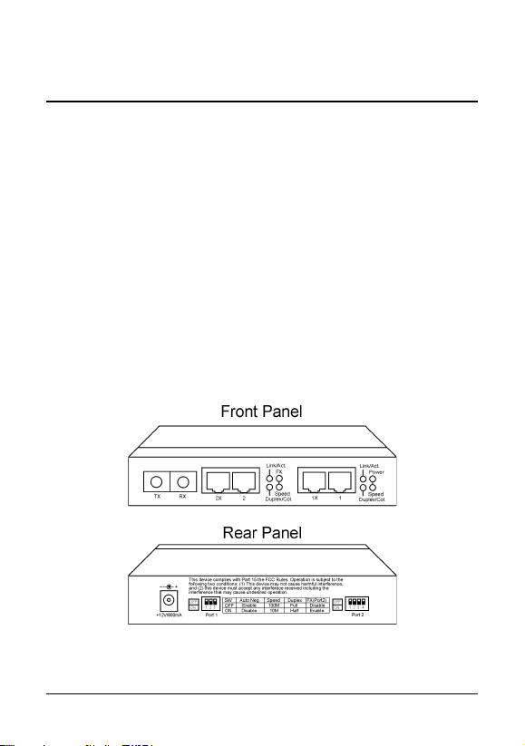
The following figure illustrates the front and rear view of the switch:
-1-
Page 6

Features
Complies with IEEE 802.3u 100BASE-TX 100BASE-FX and
IEEE 802.3 10BASE-T specifications
2 switched ports:
Port 1 - 10/100M TP port
Port 2 - configurable 10/100M TP port or 100M Fiber port
The TP ports support:
- auto speed sensing for 100Mbps or 10Mbps connection
- auto-negotiation with NWay devices
Each TP port provides one MDI-X jack and one MDI jack for
flexible connection to different devices using straight-through
UTP cable.
Each port has an individual manual setting for speed and duplex
type configuration for connecting to non-NWay devices.
Self-learning for network configuration
Store and forward switching to ensure only good packets are
forwarded
Full-duplex or half-duplex operation support for both ports
Forwarding and filtering at full wire speed
Comprehensive LED indicators
Attachable to metal surface via flexible rubber magnet
-2-
Page 7

Specifications
Standard: 10BASE-T, 100BASE-TX, and 100BASE-FX
Connectors: Port 1 - 2 RJ-45 jacks
Port 2 - 2 RJ-45 jacks and 1 fiber connector
Cables: 10BASE-T - Cat. 3, 4, or 5 UTP cable
100BASE-TX - Cat 5 UTP cable
100BASE-FX - 62.5/125µm MM fiber
100BASE-FX - 9/125µm SM fiber
LED indicators: Link/Activity LED per port, Duplex/Collision
LED per port, Speed LED per port, Power LED
FX LED for Port 2
Filtering address: 1K MAC addresses shared by two ports
Filtering rate: 14,880 pps for 10M Ethernet
148,800 pps for 100M Fast Ethernet
Forwarding rate: 14,880 pps for 10M Ethernet
148,800 pps for 100M Fast Ethernet
Power: +12VDC 800mA min.
Dimension: 144mm x 100mm x 26mm (WxDxH)
Temperature: 0o to 40oC when operating
Humidity: 10% to 90% non-condensing when operating
-3-
Page 8

2. Installation
Unpacking
Check to see that you have everything before you start the installation.
Installation guide
The unit
One AC power adapter for the switch
Installation
The switch can be placed on a desktop as a stand-alone unit. It also
can be mounted on a magnetic-sensitive metal surface with its rubber magnet stand located on the bottom of the unit.
-4-
Page 9

Checking AC Power
One AC power adapter is contained in the product package. Before
you begin the installation, check the AC voltage of your area. The
AC power adapter which is used to supply the DC power for the
unit should have the AC voltage matching the commercial power
voltage in your area.
The specifications of the AC power adapter are:
AC input power: AC power voltage of your area
DC output power:+12 VDC 800mA min.
DC plug type:
The power socket for the AC power adapter is located on the rear of
the unit as shown below:
-5-
Page 10

3. Making Network Connections
Two Switched Ports
Two switched ports are located on the front panel.
Configuration Switches
On rear panel, Port 1 and Port 2 have individual configuration switches
as shown below:
Port 1, Port 2 SW1 Off Auto-negotiation is enabled.
Port 1, Port 2 SW2 Of f 100Mbps is used. (When SW1 = On)
Port 1, Port 2 SW3 Off Full-duplex is used. (When SW1 = On)
Port 2 only SW4 Off Fiber connector is disabled.
On Auto-negotiation is disabled.
On 10Mbps is used. (When SW1 = On)
On Half-duplex is used. (When SW1 = On)
On Fiber connector is enabled.
Factory Defaults
SW1 Of f Auto-negotiation is enabled.
SW2 Off 100Mbps
SW3 Off Full-duplex
SW4 On Fiber connector is enabled.
-6-
Page 11

Important Note:
If any change are made to the configuration switch
settings, the power to the unit must be turned off and
turned on again before the changes can take effect.
The auto-negotiation mode enables the port to negotiate a common
operation mode with the device connected at the remote end of the
link cable. The common operation mode includes connection speed
and duplex type. When an operation mode is accepted by the remote device, the mode is used for the data transfer between the port
and the connected device.
TP Ports
In order to provide flexible connection to a remote device using a
popular straight-through UTP cable, each port features two types
of RJ-45 jacks.
Jack Function
1X MDI-X jack for Port #1
1 MDI jack for Port #1
2X MDI-X jack for Port #2
2 MDI jack for Port #2
The pin assignments of the jacks are defined as follows:
Pin MDI-X Jacks MDI Jacks
1 RX data + TX data +
2 RX data - TX data 3 TX data + RX data +
6 TX data - RX data 4,5,7,8 NC NC
-7-
Page 12

UTP Connections
The following figure shows a UTP connection from TP port to
another device via a straight-through UTP cable. When TP port of
Port 2 is used, make sure Port 2 SW4 is set to OFF position.
Depending on the configuration switch setting, the operating modes
used for connecting to different devices are shown as follows:
Connected Device SW1 setting Port Operation Mode
10M Ethernet hub AUTO 10BASE-T, half-duplex
100M Fast Ethernet hub AUTO 100BASE-TX, half-duplex
10/100M dual speed hub AUTO 100BASE-TX, half-duplex
10/100M NWay switch AUTO 100BASE-TX, full-duplex
10/100M NWay NIC card AUTO 100BASE-TX, full-duplex
10M Ethernet device Non-auto 10BASE-T, half-duplex
* Note that all hub devices are half-duplex devices.
Compliant UTP Cables
Connection UTP Cable Type Maximum Length
10BASE-T Cat. 3, 4, or 5 100 meters
100BASE-TX Cat. 5 100 meters
When using a straight-through cable for the connection, make sure
the MDI-X to MDI connection rule is followed.
-8-
Page 13

Fiber Port and Fiber Connection
When connecting to a 100BASE-FX device using fiber cable, make
sure Port 2 SW4 is set to ON position and TX-to-RX connection
rule is followed.
Since the fiber connector does not support auto-negotiation function, it is recommended to set SW1 to ON position for the fiber
connection. If SW1 is set to OFF, it operates on half-duplex mode.
Fiber Cables
The required fiber cable for the connection are:
Model /T model /C model /S series
Fiber mode Multimode Multimode Single mode
Wavelength 1300µm 1300µm 1300µm
Connectors ST SC SC
Multimode fiber: 50/125, 62.5/125, 85/125, 100/140µm
Single mode fiber: 9/125µm
The maximum distance connecting to a 100BASE-FX device depends on the device connected and the duplex mode used for the
connection as follows:
-9-
Page 14

MULTIMODE FIBER CABLE
Connected device Duplex type Maximum length
100Base-FX NIC card Half-duplex 400 meters
100Base-FX NIC card Full-duplex 2K meters
100Base-FX hub port *1 Half-duplex 185 meters
100Base-FX hub port *2 Half-duplex 110 meters
100Base-FX switched port Half-duplex 400 meters
100Base-FX switched port Full-duplex 2K meters
*1 : One Class II hub network
*2 : Two Class II hub network
SINGLE MODE FIBER CABLE
Connecting to Duplex type Maximum length
100Base-FX NIC card Full-duplex 15Km (S, S-A model)
100Base-FX switched port Full-duplex 15Km (S, S-A model)
100Base-FX NIC card Full-duplex 30Km (S-3 model)
100Base-FX switched port Full-duplex 30Km (S-3 model)
100Base-FX NIC card Full-duplex 50Km (S-5 model)
100Base-FX switched port Full-duplex 50Km (S-5 model)
Applications
The following table lists some applications using the device:
Applications Port 1 connection Port 2 connection
Bridging device 10M network 100M network
Distance extender* 100M hub 100M hub
Media conversion UTP cable Fiber cable
* The maximum diameter for a 100M network is 205 meters with
two Class II hubs. With the bridging converter, the network diameter can be extended up to 410 meters.
-10-
Page 15

4. Interpreting LED Indicators
The following figure shows the locations of the LED indicators:
Power
State Indication Interpretation
On Normal The power of the unit is on.
Off Problem No power is being supplied to the unit.
Link/Act. (Link/Activity)
State Indication Interpretation
On Normal An active link is established.
Off Normal No active link
Blink Normal There are data transfer activities
Duplex/Col (Full-duplex/Collision)
State Indication Interpretation
On Normal Full-duplex mode is used.
Off Normal Half-duplex mode is used.
Blink Normal Collisions occur (half-duplex is used).
Speed
State Indication Interpretation
On Normal 100M speed is selected. (Power ON default)
Off Normal 10M speed is selected.
FX
State Indication Interpretation
On Normal Fiber port is used on Port 2.
Off Normal UTP port is used on Port 2.
-11-
 Loading...