

Page 1

Installation Guide
10/100 Fast Ethernet Switch
KS-115F Series
-12-
P/N:750-0136-001
DOC.000112-KS115F-K
Page 2

1999 KTI Networks Inc. All rights reserved. No part of this documentation may be reproduced in any form or by any means or used to make
any directive work (such as translation or transformation) without permission from KTI Networks Inc.
KTI Networks Inc. reserves the right to revise this documentation and to
make changes in content from time to time without obligation on the part
of KTI Networks Inc. to provide notification of such revision or change.
For more information, contact:
United States KTI Networks Inc.
P.O. BOX 631008
Houston, Texas 77263-1008
Phone: 713-2663891
Fax: 713-2663893
E-mail: kti@ktinet.com
WWW: http://www.ktinet.com/
International Fax: 886-2-26983873
E-mail: kti@ktinet.com.tw
WWW: http://www.ktinet.com.tw/
-13-
Page 3

The information contained in this document is subject to change without prior notice.
Copyright KTI. All Rights Reserved.
TRADEMARKS
Ethernet is a registered trademark of Xerox Corp.
This device complies with Class A Part 15 the FCC Rules. Operation is subject to the following two
conditions: (1) This device may not cause harmful interference, and (2) this device must accept any
interference received including the interference that may cause.
CISPR A COMPLIANCE:
This device complies with EMC directive of the European Community and meets or exceeds the following technical standard.
EN 55022 - Limits and Methods of Measurement of Radio Interference Characteristics of Information
Technology Equipment. This device complies with CISPR Class A.
WARNING: This is a Class A product. In a domestic environment this product may cause radio interference in which case the user may be required to take adequate measures.
CE NOTICE
Marking by the symbol indicates compliance of this equipment to the EMC directive of the
European Community. Such marking is indicative that this equipment meets or exceeds the following
technical standards:
EN 55022: Limits and Methods of Measurement of Radio Interference characteristics of Information
Technology Equipment.
EN 50082/1:Generic Immunity Standard -Part 1: Domestic Commercial and Light Industry.
EN 60555-2: Disturbances in supply systems caused by household appliances and similar electrical equipment - Part 2: Harmonics.
-15-
Page 4

Table of Contents
1. Introduction ................................................................................. 1
1.1 Features ................................................................................................................. 2
1.2 Specifications ....................................................................................................... 3
2. Installing the Switch ................................................................... 4
2. 1 Unpacking ............................................................................................................ 4
2. 2 Checking AC Power ............................................................................................ 4
2. 3 Installing the Switch ............................................................................................ 5
3. Making Network Connections .................................................... 6
3. 1 Network Switched Ports ..................................................................................... 6
3.2 UTP Cable ............................................................................................................ 7
3. 3 Fiber Cable ............................................................................................................ 8
3.4 Network Connections ......................................................................................... 9
3.5 Operating Mode ................................................................................................. 10
4. LED Indicators............................................................................11
4.1 LED Panel .......................................................................................................... 1 1
4.2 Interpretation .................................................................................................... 1 1
-16-
Page 5
1. Introduction
Driven by recent advances in desktop computing technology, todays
network applications have increased in speed, power and the ability to
process information. To meet the demands of these more powerful applications, this affordable switch device provides significant increase in
performance for your Ethernet or Fast Ethernet network. This 5-port Fast
Ethernet switch comes with four 10/100 TP ports and one fiber port, each
capable of transmitting or receiving information simultaneously at full
wire speed to control and allocate the network bandwidth.
The key features of this switch unit are:
Optimized Bandwidth : Combining five 10/100Mbps-based Fast
Ethernet switched ports, the switch delivers a high network
bandwidth for your Fast Ethernet network
Easy Migration : With 10BASE-T support on each port, the switch
provides a non-disruptive and smooth migration path from
Ethernet to a Fast Ethernet network.
Fiber Uplink Support : With 100BASE-FX port, the switch provides
a connectivity to a Fast Ethernet network via fiber cable.
Easy Installation : With the functions of auto-speed-sensing and
auto-negotiation on each port, the switch supports plug-and-play
installation which eliminates configuration problems.
-1-
Page 6

1.1 Features
Designed for resolving congestion problems caused by bandwidth-hungry devices and bandwidth-intensive applications as well as a high number of users, the switches not only adhere to the IEEE 802.3 10BASE-T,
802.3u 100BASE-TX and 100BASE-FX standards, but also feature:
Four 10/100BASE-TX auto-negotiation switched ports and one
100BASE-FX port for flexible connections to desktop PCs, servers
and Ethernet hubs.
The 10/100BASE-TX switched ports support:
- auto speed sensing for 100Mbps or 10Mbps connection
- auto configuration with auto-negotiation devices
- full-duplex or half-duplex operation
For the fiber port, the switch series support variety of fiber connec-
tors for different application needs. The fiber connectors include
ST, SC, MT-RJ, and VF-45 types for multimode and single mode
fiber cables.
Supports duplex mode selector for the 100BASE-FX fiber port.
Self learning for active MAC addresses
Store and forward switching to ensure only good packets are forwarded
Forwarding and filtering at full wire speed
Supports IEEE 802.3x flow control for full-duplex operation
Supports back-pressure flow control for half-duplex operation
Comprehensive LED indicators provide quick, easy to read port
and switch information
-2-
Page 7

1.2 Specifications
Port 1 - 4 MDI-X RJ-45 jacks for 10/100BASE-TX connectivity
Port 5 One fiber connector for 100BASE-FX connectivity
Cables 10BASE-T Cat. 3, 4, 5 UTP cable (100 meters max.)
100BASE-TX Cat. 5 UTP cable (100 meters max.)
100BASE-FX multimode or single mode fiber cable
LED indicators Power status
10/100M, Link/Activity,Duplex/Collision status per port
Filtering rate 14,880 pps for Ethernet (10BASE-T)
148,800 pps for Fast Ethernet (100BASE-TX)
Forwarding rate 14,880 pps for Ethernet (10BASE-T)
148,800 pps for Fast Ethernet (100BASE-TX)
Filtering address Multicast/Broadcast/Unicast address
8K MAC addresses per unit
RAM buffers 256KB
Environment Temperature 0oC to 40oC
Relative humidity 10% to 90% non-condensing
Dimensions 144 mm x 100 mm x 26 mm (WxDxH)
5.67 x 3.94 x 1.02 inch
Power +5V 1.2A minimum
Models vs Fiber Specifications
Model Connector Fiber Cable Max. Distance
KS-115F/T ST MM
KS-115F/C SC MM 2 Km
KS-115F/SA SC SM
KS-115F/S3 SC SM 30 Km
KS-115F/S5 SC SM 50 Km
KS-115F/JM MT-RJ MM 2 Km
KS-115F/JS MT-RJ SM 15 Km
KS-1 15F/VM VF-45 MM 2 Km
KS-115F/VS VF-45 S M 15 Km
*1
*2
2Km
15 K m
*1 : Multimode fiber
*2 : Single Mode fiber
-3-
Page 8

2. Installing the Switch
2.1 Unpacking
Check to see that you have everything before you start the installation.
Installation guide
The switch unit
One AC power adapter for the unit
2.2 Checking AC Power
Before you begin the installation, check the AC voltage of your area. The
AC power adapter which is used to supply the DC power for the unit should
have the AC voltage matching the commercial power voltage in your area.
The specifications of the AC power adapter are:
AC input power: AC power voltage of your area
DC output power: +5V VDC 1.2A min.
DC plug type:
-4-
Page 9

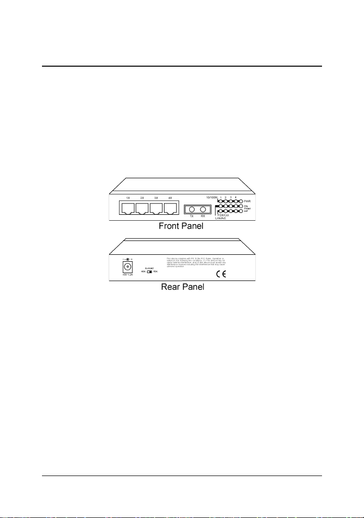
The DC power socket for the AC power adapter is located on the rear of
the switch as shown below:
2.3 Installing the Switch
1. Install the switch with the AC power adapter provided.
2. Connect the power adapter cable to the switch before connecting
the adapter to the AC outlet.
-5-
Page 10

3. Making Network Connections
3.1 Network Switched Ports
There are five ports on the switch for connection to five LAN segments.
Each segment is an independent shared network in one collision-domain.
Four 10/100BASE-TX switched ports
Each port consists of one RJ-45 connector and is used for connection to
either a 10BASE-T or 100BASE-TX device. The RJ-45 connectors are fixed
MDI-X jacks which are designed with internal crossover function. It allows
a connection to an end station using straight-through UTP cable.
One 100BASE-FX fiber switched port
This fiber port comes with one fiber connector. For ST and SC
connectors, the contact labeled TX is used for transmission and
the other one labeled RX is used for reception. One duplex mode
selector is located on the rear panel. Either full duplex or half duplex
mode can be selected (factory default: full-duplex).
-6-
Page 11

The following figure illustrates the front panels with different fiber connectors:
3.2 UTP Cable
When making a connection to another device using straight-through
UTP cable, make sure MDI-X to MDI connection rule is followed. The
following figure illustrates the pin assignments of a straight-through
UTP and a crossover UTP cable:
It is suggested to use straight-through UTP cables for all UTP connections. The maximum length and UTP cable categories used for the connections to a 10BASE-T device and 100BASE-TX device are:
CONNECTED DEVICE UTP CABLE USED & MAXIMUM LENGTH
10BASE-T device Cat. 3, 4, 5 UTP (100 meters)
100BASE-TX device Cat. 5 UTP (100 meters)
-7-
Page 12

3.3 Fiber Cables
For different fiber connections, several alternative models can be
selected for different fiber connections as follows:
Model Connector Wavelength Cable Max. Distance
KS-115F/T ST 1300nm MM
KS-115F/C SC 1300nm MM 2 K m
KS-115F/SA SC 1300nm SM
*2
*1
2Km
15 K m
*3
KS-115F/S3 SC 1300nm SM 30 K m
KS-115F/S5 SC 1300nm SM 50 K m
KS-115F/JM MT-RJ 1300nm MM 2 K m
KS-115F/JS MT-RJ 1300nm SM 15 Km
KS-115F/VM VF-45 1300nm MM 2 K m
KS-115F/VS VF-45 1300nm SM 15 Km
*1 : Multimode fiber cable
*2 : Single Mode fiber cable
*3 : The maximum distance connecting to a full duplex device
The recommended multimode fiber is 62.5/125µm and 9/125µm for single
mode fiber.
The following figure illustrates a connection example between two SC
fiber ports:
-8-
Page 13
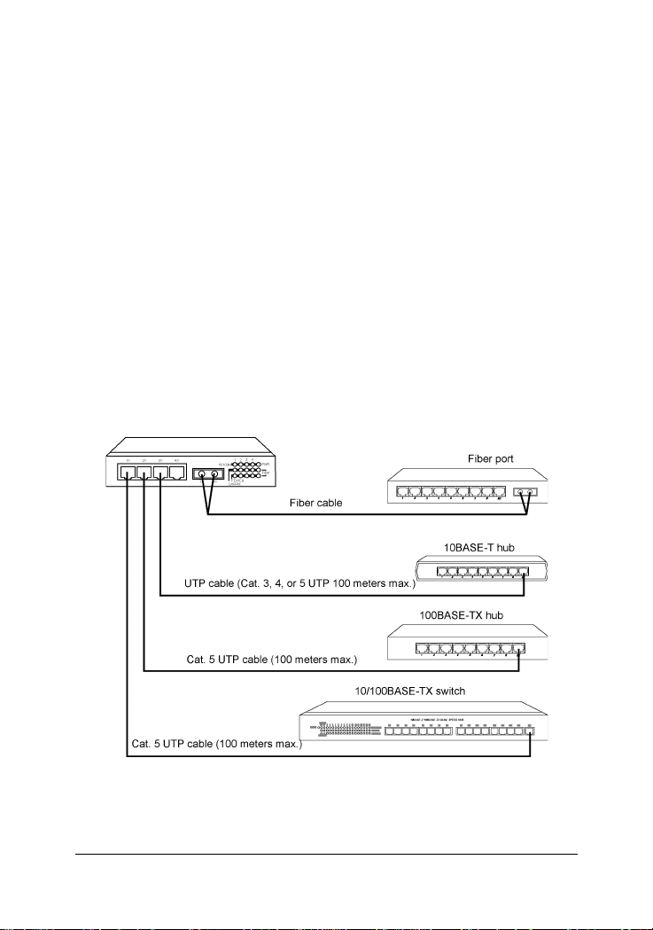
3.4 Network Connections
The switch can support connections to the following devices:
_ 10BASE-T network cards
_ 10/100BASE-TX network cards
_ 10BASE-T hub ports
_ 100BASE-TX hub ports
_ 10/100BASE-TX dual speed hub ports
_ 10/100BASE-TX switch ports
_ 100BASE-FX switch ports
The following figure illustrates some connection examples and also specifies the maximum distance of each connections:
-9-
Page 14

3.5 Operating Mode
Four TP ports are designed as auto-negotiation capable switched ports.
Each port can determine the speed and duplex type used automatically
through an auto-negotiation process with the remote connected auto-negotiation device. The auto-negotiation process is performed when the connection is made. When connecting to a non-auto-negotiation device, each
TP port also features the capability to auto-sense the connection speed.
The following table lists the operation mode used for the switched port
when it connects to different devices. The operating mode includes the
connection speed and duplex type.
Connected Device Operation Mode Used
10BASE-T hub 10Mbps, half-duplex
100BASE-TX hub 100Mbps, half-duplex
Auto-negotiation device Auto-negotiation *2
Non-auto*1 half-duplex device auto-speed-sensing *3, half-duplex
Non-auto full-duplex device Not supported
*1 Non-auto : non-auto-negotiation
*2 determined through auto-negotiation process
*3 speed is determined by auto-sensing function
Most of 10BASE-T hubs and 100BASE-TX hubs are non-auto-negotiation devices and operate on half-duplex mode.
The operating mode of the fiber port is determined by the setting of
duplex mode selector located on rear panel. The following table lists the
maximum MM fiber cable length connecting to different devices:
Connected Device Duplex Mode Distance(MM cable)
Network card Half-duplex 400 m
Network card Full-duplex 2 Km
Class I hub Half-duplex 160 m
2 Class II hubs Half-duplex 112 m
Switched fiber port Half-duplex 400 m
Switched fiber port Full-duplex 2 Km
-10-
Page 15
4. LED Indicators
4.1 LED Panel
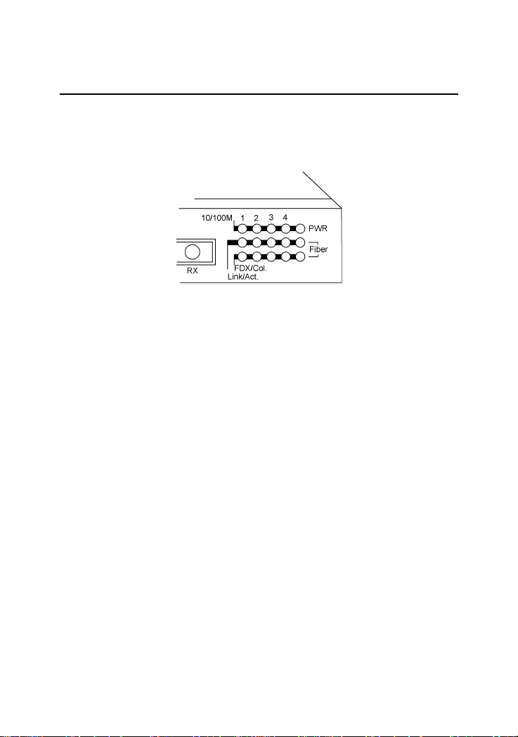
The switch provides comprehensive LED indicators for diagnosing and
monitoring the operation of the unit as illustrated below:
4.2 Interpretation
PWR LED : indicates the status of the power supplied to the switch.
10/100M LED : indicates the connection speed between the TP port
and the associated connected device.
Link/Act. LED : indicates the link status with a connected device
FDX/Col. LED : indicates the duplex mode and collision occurrences
The following table lists the LED states and the indications:
LED ST ATE INDICA TION
Power Off No power is supplied to the device.
Power On Power is supplied to the device.
10/100 Off 10Mbps is used.
10/100 On 100Mbps is used.
Link/Act. Off No active cable link
Link/Act. On An active link is established.
Link/Act. Blink Tx/Rx activities
FDX/Col On Full duplex is used.
FDX/Col Off Half duplex is used.
FDX/Col Blink Half duplex and collision occurrences
-11-
 Loading...