

Page 1
Solar controller
SOL3-7
Installation and operating
manual
Firmware version 1.07
June 2011
Page 2
Installation and operating manual KT-Elektronik
Warranty
We permanently enhance our products, therefore we reserve the right to make changes to
our products at any time and without prior notice.
We take no responsibility for the accuracy or completeness of this manual. No liability can
be accepted for the use of our products for a buyer specific purpose. Buyer claims,
especially claims for damages including lost profits or other financial losses are excluded.
This does not apply if the damage caused by intent or gross negligence. In case of
negligent violations of major contractual obligations, our liability is limited to the
foreseeable damage
Security advices
Only qualified personnel that is familiar with installation and
commissioning of this product is allowed to mount and put into operation
the device. Appropriate shipping and storage are assumed.
The product is designated for use in heavy current equipment. Installation
and maintenance have to be performed according to the corresponding
safety regulations.
2 EB_37388_SOL3-7_EN001
Page 3

KT-Elektronik SOL3-7
Table of contents
1 Operation .......................................................................................................................... 6
1.1 Controls ...................................................................................................................... 6
1.1.1 Rotary switch ....................................................................................................... 7
1.1.2 Rotary pushbutton .............................................................................................. 7
1.2 Operating .................................................................................................................. 8
1.3 Display ...................................................................................................................... 8
1.3.1 System scheme ................................................................................................... 9
1.3.2 Operating Mode ................................................................................................ 10
1.4 Retrieving data – Information level .......................................................................... 11
1.5 Setting the system time ............................................................................................ 12
1.6 Adjust usage schedule settings ............................................................................... 13
1.7 Setting the party mode (heating circuit/auxiliary heating) ........................................ 15
1.8 Setting holidays ........................................................................................................ 16
1.9 Setting vacation times .............................................................................................. 17
1.10 Access advanced information level ........................................................................ 18
1.11 Trend show – Data logging .................................................................................... 20
2 Commissioning ............................................................................................................... 22
2.1 Set language ........................................................................................................... 22
2.2 Setting the system variant ID ................................................................................... 23
2.3 Activate and deactivate functions ............................................................................ 24
2.4 Edit settings ............................................................................................................. 26
2.5 Sensor calibration .................................................................................................... 28
2.6 Reset to factory default settings ............................................................................... 29
3 Manual operating mode .................................................................................................. 30
4 System variants .............................................................................................................. 31
4.1 Extending the basic system variant representations ................................................ 40
5 Solar circuit functions ..................................................................................................... 43
5.1 Basic Control function .............................................................................................. 43
5.2 Storage .................................................................................................................... 45
5.3 Swimming pool ......................................................................................................... 46
5.4 Collector return flow sensor, Collector flow sensor .................................................. 47
5.5 Measurement of solar power and solar energy ........................................................ 48
5.6 Rotation speed control ............................................................................................. 49
5.7 Collector overheating protection .............................................................................. 50
5.8 Collector minimum temperature ............................................................................... 51
5.9 Start up function ....................................................................................................... 51
5.10 Forced pump operation (blocking protection) ........................................................ 51
5.11 Collector Antifreeze ................................................................................................ 52
5.12 Two collector arrays ............................................................................................... 52
EB_37388_SOL3-7_EN001 3
Page 4

Installation and operating manual KT-Elektronik
5.13 External heat exchanger ........................................................................................ 53
5.14 Auxiliary heating with secondary heat generator ................................................... 53
6 Heating circuit functions ................................................................................................. 55
6.1 Prescribing the room temperature set-points ........................................................... 55
6.2 Weather-compensated control ................................................................................. 55
6.2.1 Gradient characteristic ..................................................................................... 55
6.2.2 4-point characteristic ......................................................................................... 57
6.3 3-point control .......................................................................................................... 59
6.4 Two-point control ..................................................................................................... 59
6.5 Underfloor heating/screed drying ............................................................................. 60
6.6 Deactivation depending on the outdoor temperature ............................................... 61
6.6.1 OT deactivation temperature for daytime operating mode ................................ 61
6.6.2 OT deactivation temperature for night-time operating mode ............................. 61
6.6.3 OT activation temperature for daytime operating mode .................................... 61
6.6.4 Summer operating mode (OM) .......................................................................... 62
6.7 Delayed outside temperature compensation ........................................................... 62
6.8 Remote operation .................................................................................................... 63
6.9 Optimization ............................................................................................................. 63
6.10 Raise return flow of external heating system ........................................................ 64
6.10.1 Main principle .................................................................................................. 64
6.10.2 Implementation ................................................................................................ 65
7 Domestic water circuit functions ..................................................................................... 66
7.1 Domestic water heating in storage tank ................................................................... 66
7.2 Thermal Disinfection of the storage tank ................................................................. 66
8 System wide functions - all system variants ................................................................... 67
8.1 Automatic summer/winter switching ......................................................................... 67
8.2 Antifreeze ................................................................................................................. 67
8.3 Locking manual operating mode .............................................................................. 68
8.4 Locking the rotary switch ......................................................................................... 68
8.5 Enter a valid individual access code ........................................................................ 68
8.6 Temperature difference controller ............................................................................ 69
9 Malfunction ..................................................................................................................... 70
9.1 Error list .................................................................................................................... 70
9.2 Sensor failure ........................................................................................................... 70
9.3 Temperature monitoring ........................................................................................... 71
9.4 Error status register ................................................................................................. 71
9.5 SMS delivery in case of a system failure ................................................................. 72
10 Communication ............................................................................................................ 73
10.1 Communication module KOM232PC .................................................................... 74
10.2 Communication module iCon485 .......................................................................... 74
4 EB_37388_SOL3-7_EN001
Page 5

KT-Elektronik SOL3-7
10.3 Communication module KOM232M ...................................................................... 76
10.4 Data Modem DataMod11 ...................................................................................... 77
10.5 ModBus-MBus-Gateway ....................................................................................... 78
10.6 USB communication cable USB-L3 ...................................................................... 79
10.7 Modbus-TCP-Gateway ......................................................................................... 80
10.8 Description of the adjustable communication settings .......................................... 80
10.9 Memory module .................................................................................................... 81
10.10 55Viewer for visualization and remote maintenance. ......................................... 82
10.11 Data Logging ....................................................................................................... 83
11 Mounting ....................................................................................................................... 84
12 Electrical connection ..................................................................................................... 86
12.1 Notes for wire installation ....................................................................................... 86
12.2 Surge Protection Measures ................................................................................... 86
12.3 Connecting the controller ....................................................................................... 86
12.3.1 Connecting the sensors ................................................................................... 87
12.3.2 Connecting the pumps .................................................................................... 87
12.3.3 Legend for connection diagram ....................................................................... 87
12.3.4 Wiring diagram ................................................................................................ 88
12.3.5 Terminal assignment for Outputs .................................................................... 89
12.3.6 Terminal assignment for inputs ....................................................................... 92
13 Appendix ....................................................................................................................... 93
13.1 Function block lists ................................................................................................. 93
13.2 Parameter list ......................................................................................................... 97
13.3 Resistance values ................................................................................................ 100
13.4 Technical specifications ....................................................................................... 101
13.5 Accessories .......................................................................................................... 102
13.6 Function block settings in configuration levels ..................................................... 103
13.7 Einstellungen in den Parameterebenen .............................................................. 104
13.8 Abbreviations ....................................................................................................... 106
13.9 Access codes ....................................................................................................... 107
13.10 Notes .................................................................................................................. 108
EB_37388_SOL3-7_EN001 5
Page 6
Installation and operating manual KT-Elektronik
1 Operation
The controller is factory-provided with standard temperature settings and timing programs
and therefore ready for use.
The current date and time have to be set at initial operation of the controller (Chapter
1.5).
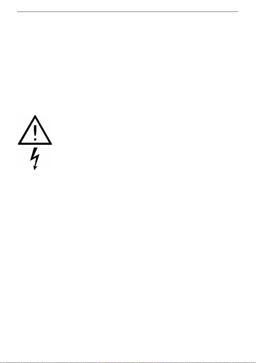
1.1 Controls
The operational controls are located on the front side of the controller.
The user is guided by means of rotary switches and pressing the control button described
below control levels.
6 EB_37388_SOL3-7_EN001
Bedienknopf
Drehschalter
Anzeige
Page 7
KT-Elektronik SOL3-7
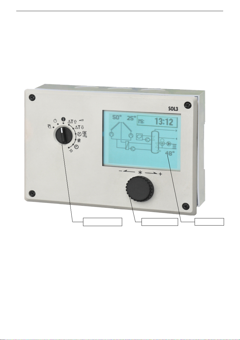
1.1.1 Rotary switch
The rotary switch is used to select the operating mode on the left hand and the basic
settings of the controller on the right hand.
Rotary switch – operating mode
Control on, display informations about
operating behaviour of unit (standard position)
Turning off the control functions
(Controller remains in operation)
Manual operating mode:
manual switching of pumps and valves,
position presetting in percent
Rotary switch – Settings
Solar-Turn-on threshold
Solar-Turn-off threshold
Scheduled time ranges and operating modes for
heating circuit (1), aux. heating (2) and hot water
circulation (3)
Party mode
System time:
Setting time, date and year
Configuration and settings level
1.1.2 Rotary pushbutton
The rotary pushbutton is an integral part of the intuitive operating concept, with only one
button.
Turn :
Display, select settings and function blocks
Push :
confirm selection or setting
EB_37388_SOL3-7_EN001 7
Page 8
Installation and operating manual KT-Elektronik
1.2 Operating
The operation of the device SOL3-7follows a continuous uniform display and operating
philosophy.
Values and display texts are shown in black characters with no background. Elements for
direct input or selection are shown with white characters on black background. Choice
elements in rows oriented menus are shown with black characters on a gray background.
With the help of the rotary switch, a control level is set. The rotary pushbutton is used to
select and adjust.
1.3 Display
The controller SOL3-7 it equipped with a graphical display. The display allows it to
visualize the current system scheme with all relevant sensor informations as welll as state
informations of pumps and valves for a quick overview of the operating condition of the
system.
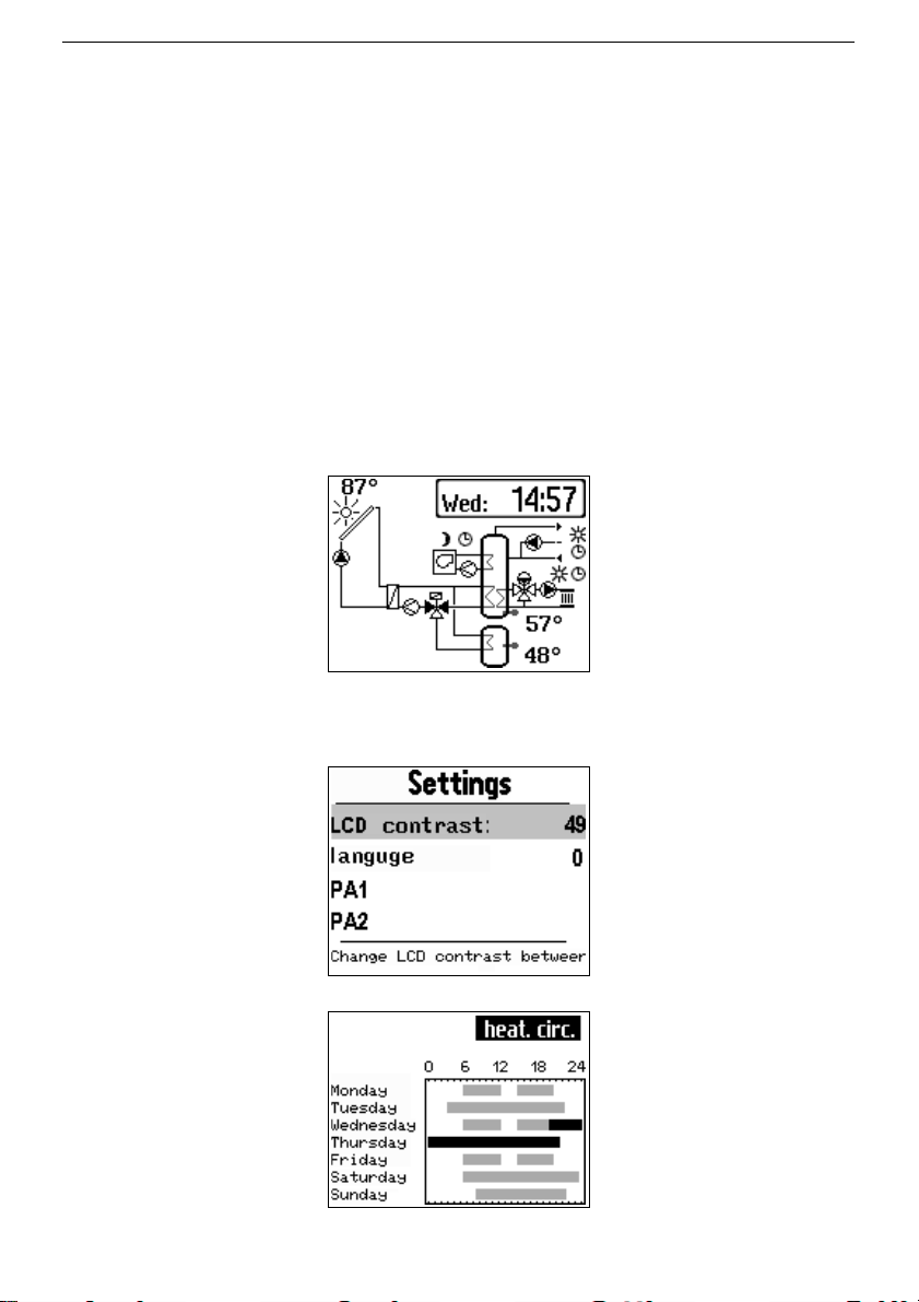
Example of display in the information level:
For the use of the device the user is facilitated in operating levels for display and input of
operating parameters with clear text menus and explanatory texts.
Example of display in the setting level:
Example of display for checking and modifying of times-of-use (weekly schedule):
8 EB_37388_SOL3-7_EN001
Page 9
KT-Elektronik SOL3-7
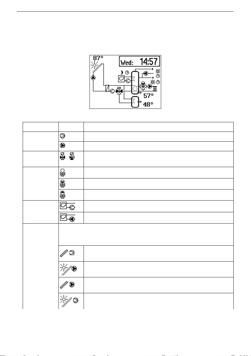
1.3.1 System scheme
With the on the display shown system scheme, the relevant sensor information, the
operating mode of the control circuits and state information of pumps and valves for a
quick overview of the operating condition can be visualized.
Among the symbols used in the system scheme are the following:
Element Symbol Meaning
Pump
Pump is in operation
Pump is not in operation
Switching
valve
Switching valve is showen with filled triangles
Valve
Valve is not in operation
Valve 'CLOSE' is in operation
Valve 'OPEN' is in operation
Auxilary
heating
Auxilary heating is not in operation
Auxilary heating is in operation
Collector
pump
A temporarily shown sun above a collector represents an
operating state indication of the pump belonging to the
collector.
Condition for the activation of the pump is not met and the
pump is not operating.
Condition for the activation of the pump is met and the pump
is operating.
The condition for switching off the pump is met, but pump is
due to the minimum ON time still in operation.
Condition for switching on the pump is met, but pump is due
to the minimum OFF time yet in operation.
EB_37388_SOL3-7_EN001 9
Page 10
Installation and operating manual KT-Elektronik
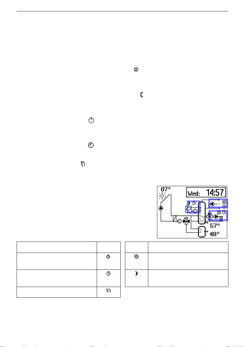
1.3.2 Operating Mode
The operation of the heating circuit, hot water circulation and auxilary heating can be
affected depending on time and day of week. There are two different set-points for night
and day exist. A usage schedule determines when to operate in day-time operating mode
or night-time operating mode. It is possible to deactivate schedules (without deleting them)
and to specify manually to operate permanently in day-time or night-time operating mode.
Icons on the display indicate the current operating mode for each function of the controller:
Daytime operating mode (nominal operation)
Values are permanently adjusted to meet the set-points entered for nominal operating
mode regardless of scheduled time ranges or summer operating mode settings.
Night-time operating mode (reduced operation)
Values are permanently adjusted to meet the set-points entered for reduced operation
regardless of scheduled time ranges.
Normal operating mode off
Normal operating mode is deactivated regardless of the scheduled time ranges. Only
equipment anti-freeze is ensured (if activated).
Automatic operating mode
The controller automatically switches between both modes depending on the time.
Manual operating mode
Manual control of valves and pumps (Chapter 3).
The operating modes of heating circuit, hot water
circulation and auxilary heating are in the system scheme,
context-sensitive arranged and allow capture at a glance
the current function of the system part.
Operating mode Symbol Symbol Time phase
Standby Nominal operation
(Day mode)
Automatic mode Reduced operation
(Night mode)
Manual mode
10 EB_37388_SOL3-7_EN001
Page 11
KT-Elektronik SOL3-7
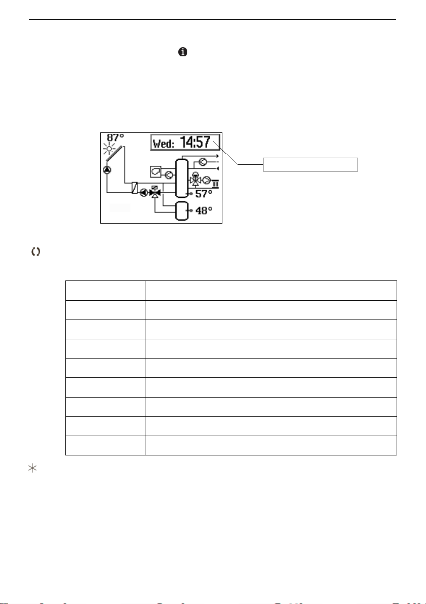
1.4 Retrieving data – Information level
At the normal rotary switch position ,„Information level“, the system scheme, time, date
as well as relevant temperatures measured by the connected sensors and state
informations of pumps and valves of the selected hydraulc schema.
By turning and pushing the rotary pushbutton it is possible to show time, date, temperature,
and query the values of connected sensors and their setpoints.
Procedure:
Select value:
In the display appears, depending on system configuration, successively the
different data points, which are described by an acronym:
Sample displays Meaning
So: 14:57 Time
AF: -5.3°C Outdoor temperature AF
RF: 20.4°C Room temperature RF
VF: 34.1°C
Temperature at flow sensor of heating circuit VF
SF1: 52.9°C Temperature at storage tank sensorr SF1
CF1: 27.3°C Temperature at collector sensor CF1
coll 12 h Operating hours of solar circiut
trend show Graphical presentation of logged system data
Setpoint or limit value compared to the displayed value.
Pushing the rotary pushbutton in the clock display shows the date and year.
Additional values can be displayed in the optional, advanced level of information (Kapitel
1.10).
EB_37388_SOL3-7_EN001 11
Display area
Page 12
Installation and operating manual KT-Elektronik
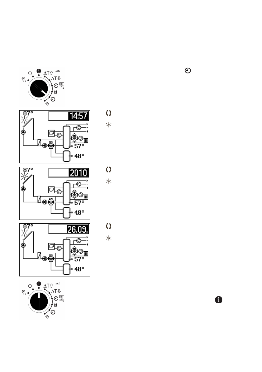
1.5 Setting the system time
The current time and date must be set immediately after the commision and after a power
failure of more than 24 hours. In this case, the system time on the clock 01/01/2000 10:00
preset and is displayed inverted (white on black) .
Procedure:
Set rotary switch to time
Display: System scheme and time(inverted)
Edit time
Confirm time
Display: System scheme and year (inverted)
Edit year
Confirm year Jahreszahl übernehmen.
Display: System scheme and year (inverted)
Format: day.month
Edite date
Confirm date
Display: System scheme and time (inverted)
Set rotary switch to Information level
12 EB_37388_SOL3-7_EN001
Page 13
KT-Elektronik SOL3-7
1.6 Adjust usage schedule settings
There are three separate usage schedules for
• Heating circuit
• Auxiliary heating
• Domestic water circulation
For systems that do not contain the functional groups mentioned, this chapter has no
meaning, the display and input of times-of-use is not offered by the SOL3-7.
The following applies to each usage schedule:
For each day of the week, three time ranges can be programmed. If only one time range is
needed, the start and end time of the second range have to be set to the same value. The
third range will then not be shown any more.
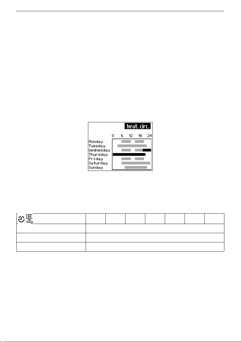
A usage schedule is presented as a weekly schedule. For each day there is shown every
interval (time-to-use) for nominal operation (day) by a gray bar chart. A black bar indicates
a time in addition to the party program set-operation (chapter 1.7).
To check the set times of use should the group of days (Monday to Sunday, Monday to
Friday, Saturday and Sunday) are not used. If this menu, even after adjustment of
schedule settings opened, the times-of-use of Monday will transfered to all other days of
week.
Factory defaults
Times Mo Tue Wed Thu Fr Sa Su
Heating circuit 06:00 – 22:00
Auxiliary heating - - : - - – - - : - Domestic water circulation 00:00 – 24:00
EB_37388_SOL3-7_EN001 13
Page 14
Installation and operating manual KT-Elektronik
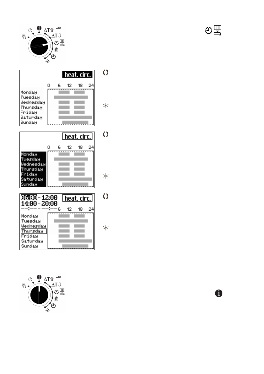
Procedure:
Set rotary switch to times-of-use
Times-of-use for heating circiut is graphicaly
shown, name of times-of-use is displayed
inverted.
Select times-of-use to view
• heating circuit
• hot water circulation
• auxilary heating
Confirm times-of-use to modify
Display:
Selection 'Monday to Sunday' (inverted)
Select day of week (inverted):
• Monday to Sunday
• Monday to Friday
• Saturday to Sunday
• single day
Confirm day of week (interval)
Display: Start and stop time for day of week
Edit start time (inverted):
• 15 minute increment
• 00:00 to 24:00
• - - : - - deaktivated
Confirm Start or stop time
Anzeige: next start or stop time
After confirming the maximum 6 times the
selection of the day of week starts again.
Repeat these steps for the daily input in the
same order.
Set rotary switch to Information level
14 EB_37388_SOL3-7_EN001
Page 15
KT-Elektronik SOL3-7
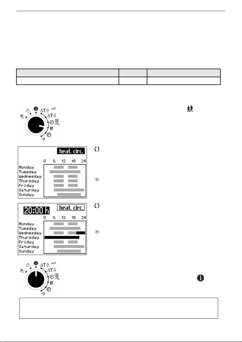
1.7 Setting the party mode (heating circuit/auxiliary heating)
Using the Party mode function, the controller continues or activates the nominal operating
mode (day) during the time when the party timer is active, regardless of the programmed
times-of-use. The activation of the party mode (count down) starts with turning the rotary
switch to any operating mode position (e.g.information level). When the party timer has
elapsed, the party mode timer is reset to 00:00 and the controller continue working as
programmed times-of-use.
Setting FS Value range
initiate or continue nominal operation 0 h 0 to 48 h
Procedure:
Set rotary switch to party mode
Display: weekly schedule
(name of times-of-use is displayed inverted.)
Select times-of-use
• heating circuit
• auxilary heating
Confirm times-of-use
Display: Current Party timer (inverted)
Edit desired duration of time-of-use
The party time is displayed across days.
Confirm Party timer
Display: weekly schedule
(name of times-of-use is displayed inverted.)
Set rotary switch to Information level
EB_37388_SOL3-7_EN001 15
Note:
The lapse of time of the party timer is displayed in 15 minute increments.
Page 16
Installation and operating manual KT-Elektronik
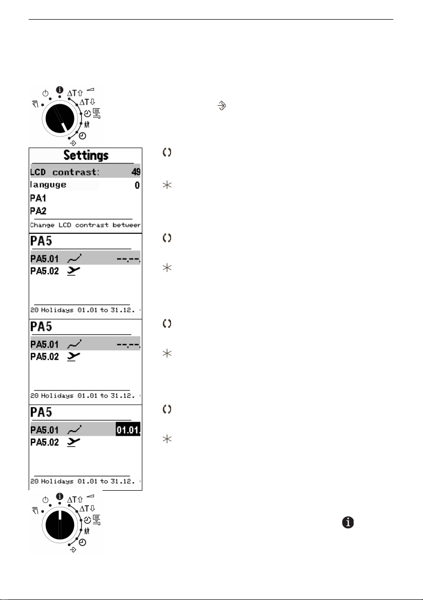
1.8 Setting holidays
On public holidays the times-of-use entered for Sunday apply. The number of programmable holidays is limited to 20. Once programmed the holidays are valid every year.
Procedure:
Set rotary switch to configuration and settings
level
Display: Settings menue (LCD contrast selected)
Select item 'PA5'
Confirm selection
Select item 'PA5.01'
Confirm selection
Display: date of holiday or placeholder
Select date of holiday or placeholder
Confirm date or placeholder to modify
Display: Date of holiday (inverted)
Edit date of holiday (day.month) or erase the date
by select placeholder '--.--' (01.01 to 31.12)
Confirm input
Display: Modified date or placeholder
(edit further holidays)
Set rotary switch to Information level
16 EB_37388_SOL3-7_EN001
Page 17
KT-Elektronik SOL3-7
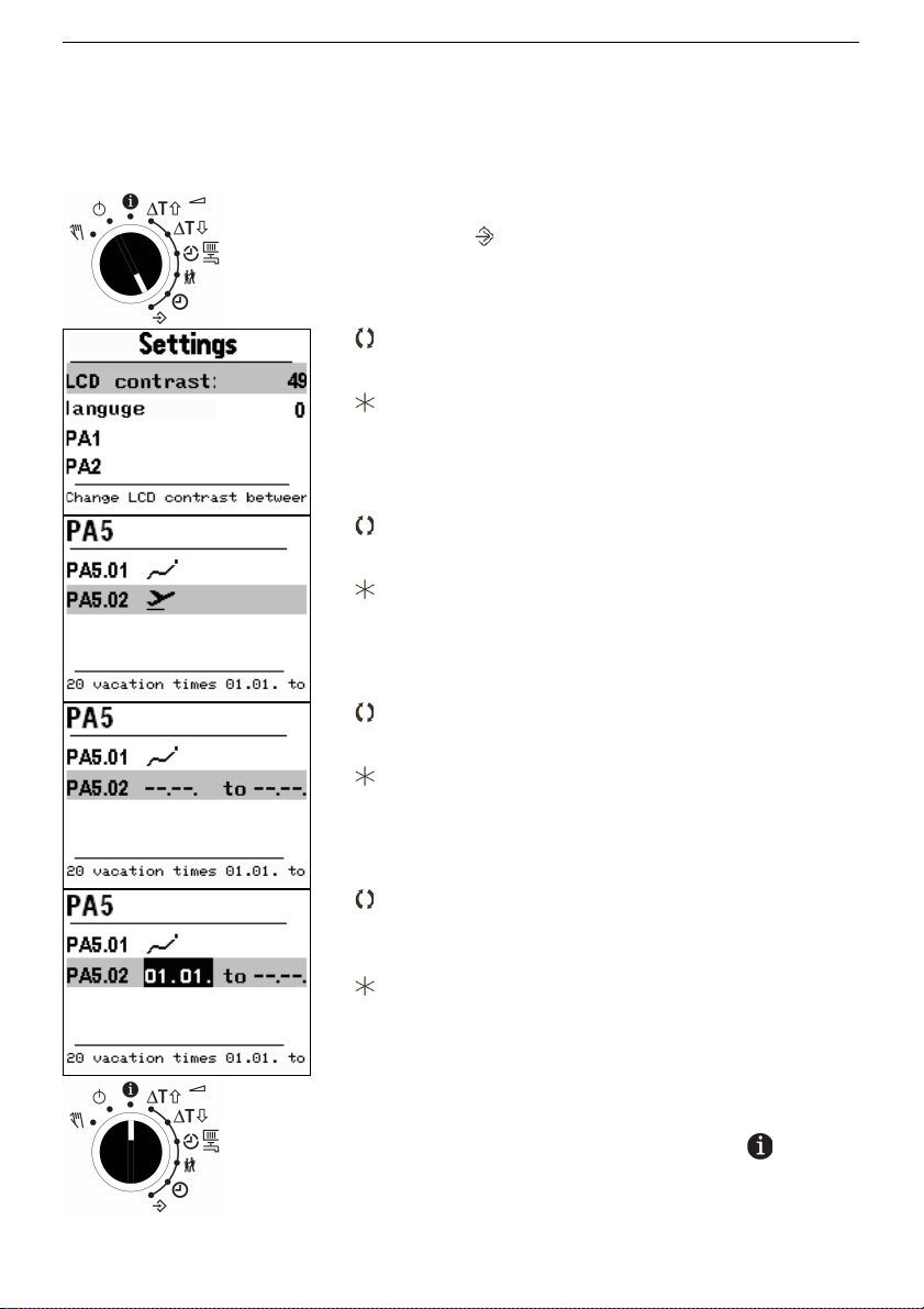
1.9 Setting vacation times
During vacation times the system is set to permanent reduced operation. The number of
programmable vacation times is limited to 10.
Procedure:
Set rotary switch to configuration and settings
level
Display: Settings menue (LCD contrast selected)
Select item 'PA5'
Confirm selection
Select item 'PA5.02'
Confirm selection
Display: vacation time or placeholder
Select vacation time or placeholder
Confirm vacation time or placeholder to modify
Display: Vacation time (inverted)
Edit vacation time by set first and last day of
vacation period (day.month) or erase the date by
select placeholder '--.--' (01.01 to 31.12)
Confirm input
Display: Modified date or placeholder
(edit further vacation time)
Set rotary switch to Information level
EB_37388_SOL3-7_EN001 17
Page 18

Installation and operating manual KT-Elektronik
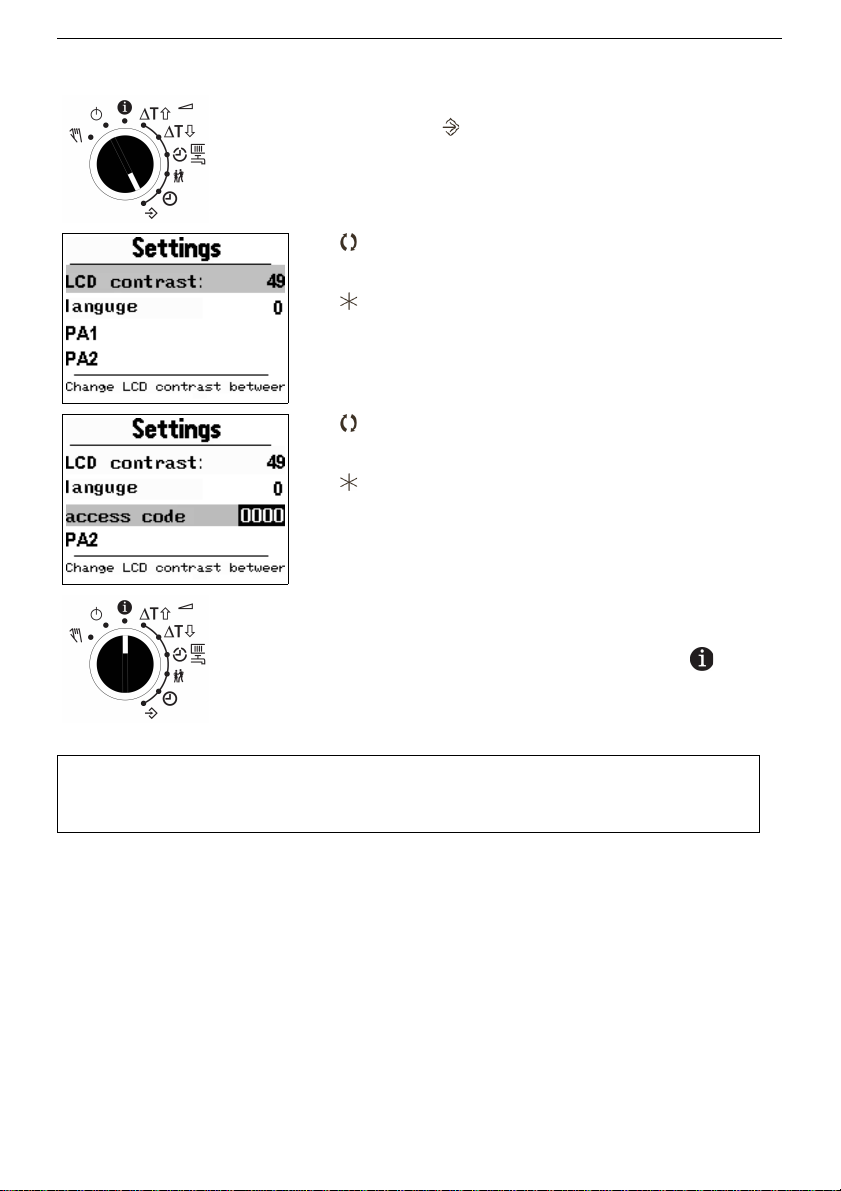
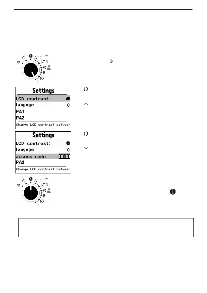
1.10 Access advanced information level
After entering the access code 1999 the following informations are accessible through the
menu items as described in chapter 1.4:
•Measured values for not needed sensor inputs of current system layout
•Valve positions
•Binary input switching status
•Modem state
•Data of M-Bus meters
•Info II - The following values are sequentially displayed:
ID Controller ID
Logg Memory usage of data logging-module (Kapitel 10.11)
MBAd Station address
Koll Operating hours of solar circuit
V' Volume flow rate of flow sensor in solar circui
Pakt Current performance of solar circuit
Wtot Total gain (rate) of solar circuit
WTag Daily gain of solar circuit
18 EB_37388_SOL3-7_EN001
Page 19
KT-Elektronik SOL3-7
Provide advanced information level:
Set rotary switch to configuration and settings
level
Display: Settings menue (LCD contrast
selected)
Select item 'PA1' (respectively 'PA3')
Confirm selection
Set access code (key number) 1999
Confirm access code (key number) 1999
Display: Settings menue ('PA1' selected)
Set rotary switch to Information level
EB_37388_SOL3-7_EN001 19
Note:
Re-entering the access code 1999 hides the advanced informations.
Page 20

Installation and operating manual KT-Elektronik
1.11 Trend show – Data logging
The device SOL3-7 is equipped with an internal memory capacity. Every minute the
controller saves data into this memory, in order to analyze in retrospect the operation of the
device without use of additional tools.
The internal backup includes:
• Sensor readings
• States of the switching outputs
• Error Status Register and archive
• Access to controller settings
• user-defined data points
The trend display shows a graph of up to 3 selectable data points with exactly 160 values.
The display area is determined based on the variable minimum and maximum values in the
range of 160 displayed records.
One record will be selected through a focus (vertical line in the display area). The recording
time stamp below the center and the values in plain text on the left side of the display area
are displayed.
With the control button, the displayed time range can be changed and adjusted to the
middle of the display area.
20 EB_37388_SOL3-7_EN001
Page 21
KT-Elektronik SOL3-7
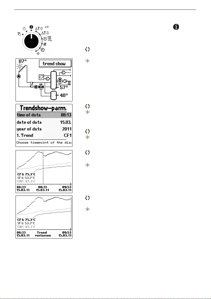
Usage of the trend show
Set rotary switch to Information level
Display: System scheme
Select 'trend show'
Confirm Selection 'trend show'
Display: Trend show settings
Select item
Confirm selection to modify the item
Select 'end'
Confirm selection 'end'
Display: Trend show
Move focus to show values of records
Set focus to the middle of the display area
(readjust time domain)
Moving the focus to the right or left edge
Leave trend show
Display: System scheme
EB_37388_SOL3-7_EN001 21
Page 22
Installation and operating manual KT-Elektronik
2 Commissioning
The configuration procedures and parametrization described in this chapter can only be
performed by entering a valid controller access code.
The access code provided by the factory for first time use can be found in the appendix. To
avoid an unauthorized use, it is recommended to cut out or black out the code. Additionally
the standard code can be replaced by an individual one (Chapter 8.5).
2.1 Set language
The device SOL3-7 will delivered with german language as factory default language. It is
possible to use other languages.
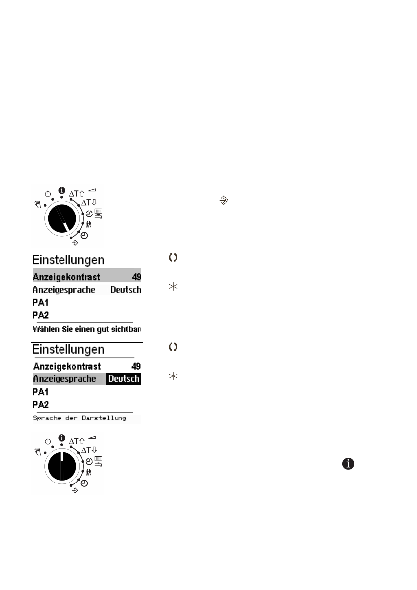
Procedure:
Set rotary switch to configuration and settings
level
Display: Settings menue (LCD contrast
selected- Language German as default)
Select 'Anzeigesprache' in Settings menue
Confirm selection
Display: Current languages (inverted)
Select your prefered language
Confirm language
Display:
Settings menue in the chosen language
Set rotary switch to Information level
22 EB_37388_SOL3-7_EN001
Page 23
KT-Elektronik SOL3-7
2.2 Setting the system variant ID
Several hydraulic system variants are available. Each variant is represented by an
identification number. The variants are illustrated in chapter 4. The available controller
functions are described in chapters 5, 6 and 7.
Editing the variant ID resets previously entered function blocks to factory default settings.
At parameter level, function block parameters and settings will be preserved. The variant
ID can be set at configuration level.
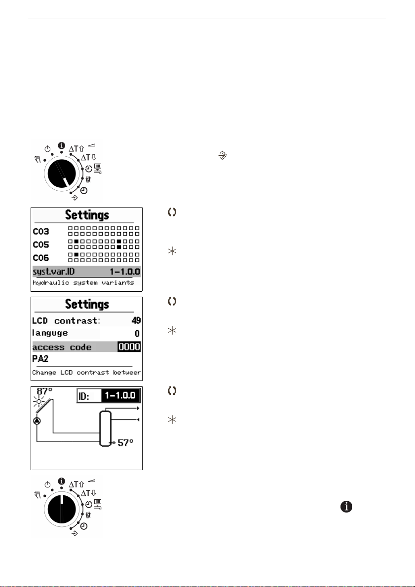
Procedure:
Set rotary switch to configuration and settings
level
Display: Settings menue (LCD contrast
selected)
Select 'syst.var.id' in Settings menue (system
code number)
Confirm selection
Display: Access code (Key number)
Set valid key number (chapter13.9)
Confirm key number
Display: System scheme
(system code number inverted)
Select system scheme
Confirm system
Display: Settings menue
(Item 'syst.var.id' selected)
Set rotary switch to Information level
EB_37388_SOL3-7_EN001 23
Page 24

Installation and operating manual KT-Elektronik
2.3 Activate and deactivate functions
Each function can be activated within its related function block. The sequence of numbers
shown at the head of the display (0 to 24) represent the function block numbers. When
accessing the configuration level, a black square is displayed right hand below active
function block numbers. The function blocks are described in chapter 13.1.
The functions are grouped by topic:
CO1: Heating circuit
CO3: Solar circuit
CO4: Domestic water circuit/auxiliary heating
CO5: System wide
CO6: Modbus-Communication
Function block parameters
Some functions that can be configured via function blocks require additional parameters.
This function block parameter will queried to edit or to confirm in the line of the function
block after function block is activated or deactivated.
24 EB_37388_SOL3-7_EN001
Page 25
KT-Elektronik SOL3-7
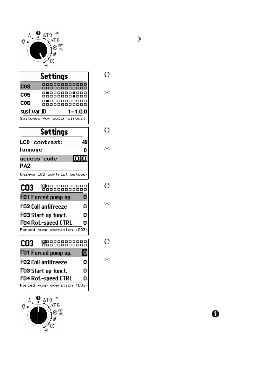
Procedure:
Set rotary switch to configuration and settings
level
Display: Settings menue (LCD contrast
selected)
Select 'CO3' in Settings menue
Confirm selection
Display: Access code (Key number)
Set valid key number (chapter13.9)
Confirm key number
Display: Configuration menue 'CO3'
Select funktion to activate or deactivate function
(1/0)
Confirm selection
Display: 'F01 Forced pump op. 0'
(Function block value inverted)
Activate or deactivate function (1/0)
Selektion bestätigen
Anzeige: Configuration menue 'CO3'
Set rotary switch to Information level
EB_37388_SOL3-7_EN001 25
Page 26

Installation and operating manual KT-Elektronik
2.4 Edit settings
Depending on the current system variant ID and active functions, not all parameters listed
in the parameter list in the Appendix will be accessible (Chapter 13.2). The functions are
grouped by topic:
PA1: Heating circuit
PA3: Solar circuit
PA4: Domestic water circuit / auxiliary heating
PA5: System wide
PA6: Modbus Communication
26 EB_37388_SOL3-7_EN001
Page 27
KT-Elektronik SOL3-7
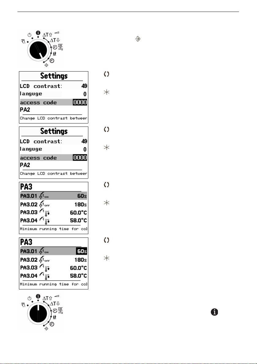
Procedure:
Set rotary switch to configuration and settings
level
Display: Settings menue (LCD contrast
selected)
Select 'PA3' in Settings menue
Confirm selection
Display: Access code (Key number)
Set valid key number (chapter13.9)
Confirm key number
Display: Settings menue 'PA3'
Select setting
Confirm setting to modify
Display: Setting menue 'PA3'
(Value inverted)
Edit setting
Confirm setting
Display: Setting menue 'PA3
(Line 'PA3.01' selected)
Set rotary switch to Information level
EB_37388_SOL3-7_EN001 27
Page 28

Installation and operating manual KT-Elektronik
2.5 Sensor calibration
The controller is designed for connection of Pt1000-sensors. The sensor values of
resistance are listed on page 100.
If the temperature values displayed by the controller do not match the real temperatures,
the measured values of the connected sensors can be adjusted. The temperature value
displayed has to be replaced by the value measured directly at the measuring point
(reference value). The adjustment has to be activated in CO5, function block F20. A wrong
adjustment can be deleted (for all inputs) by setting - 0 in F20.
Procedure:
Select the function block according to chapter 2.3 CO5.F20 "Sensor calibrat" and activate
or confirm the function block set.
As a function block parameter are viewed with turning the rotary pushbutton all in the
chosen hydraulic system used temperature sensor inputs. If the rotary pushbutton is
pushed, the displayed value is inverted for input.
By turning the rotary pushbutten edit the reference value as an actual temperature of a
thermometer directly at the measuring point and confirm by pressing the rotary pushbutton.
Proceed in this manner to be aligned with each temperature sensor input.
28 EB_37388_SOL3-7_EN001
Page 29
KT-Elektronik SOL3-7
2.6 Reset to factory default settings
All parameters set by means of the rotary switch as well as the parameters set in level PA1
to PA5 can be reset to factory default settings, except the maximum flow temperature and
return flow temperature thresholds in level PA1.
Procedure:
Set rotary switch to configuration and settings
level
Display: Settings menue (LCD contrast
selected)
Select item 'PA1' (respectively 'PA3')
Confirm selection
Set access code (key number) 1991
Confirm access code (key number) 1991
Display: Settings menue ('PA1' selected)
Set rotary switch to Information level
EB_37388_SOL3-7_EN001 29
Note: The error message "Error 2" will be generated while resetting to the factory
default settings. It will be removed automatically shortly after midnight.
Page 30
Installation and operating manual KT-Elektronik
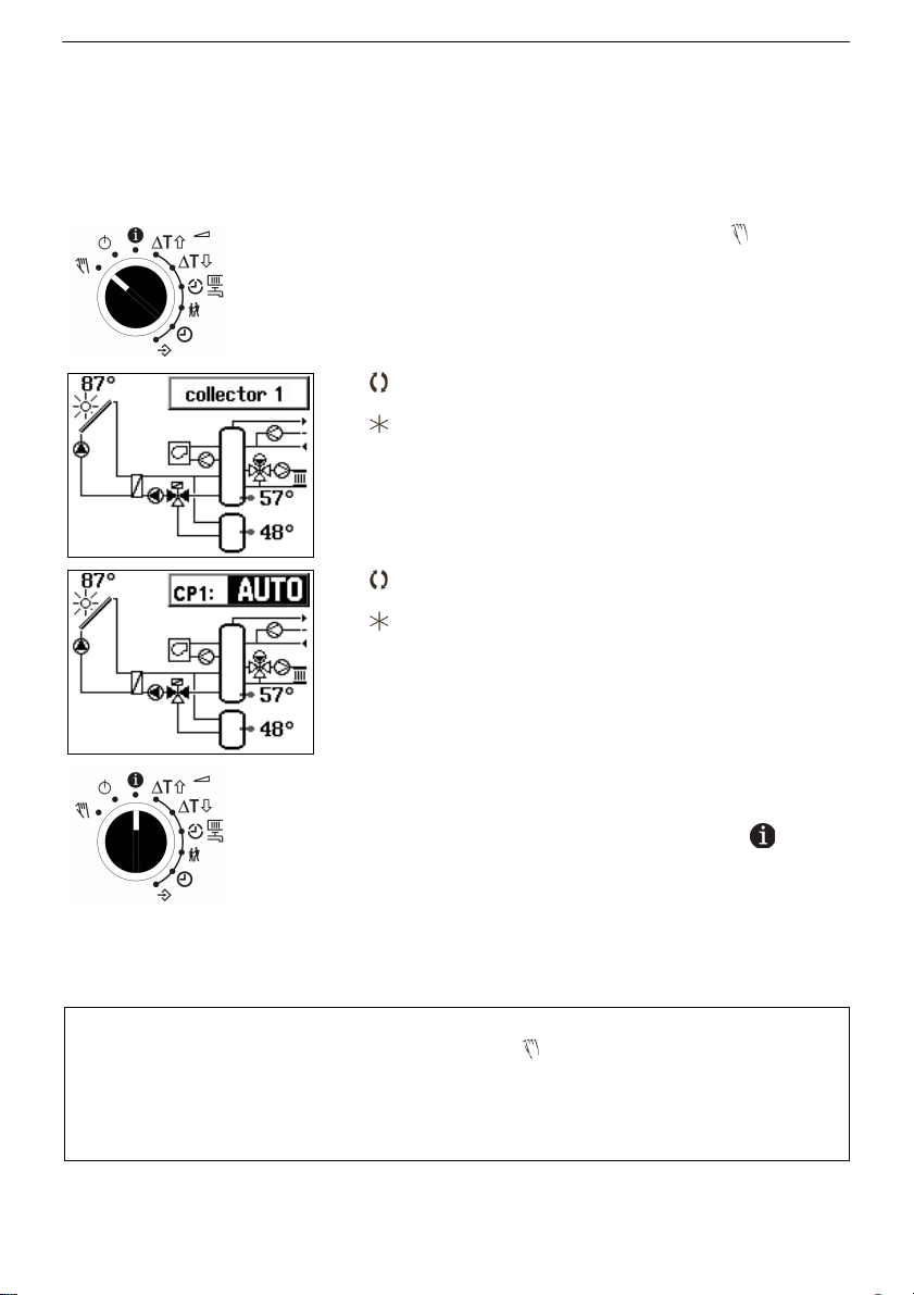
3 Manual operating mode
The manual operating mode allows the configuration of all outputs
(chapter 12).
Procedure:
Set rotary switch to manual mode
Display: System scheme and 'Collector 1'
Select switching output or valve
Confirm selected output
Display: System scheme and current state of
collector pump 1 (inverted)
Edit state of output
Confirm state of output
Display: System scheme and 'Collector 1'
Set rotary switch to Information level
The manual operating mode of the affected control circuit can be deactivated by selecting
any other operating mode.
30 EB_37388_SOL3-7_EN001
Note:
Just by moving the rotary switch to the position “manual operating mode”, the
outputs of the controller are not affected. Only the specific change of position
respectively switching status will influence them.
In manual operating mode the antifreeze function can not be guaranteed (Chapter 8.2).
Page 31

KT-Elektronik SOL3-7
4 System variants
117 hydraulic system variants are available. They differ in the first instance in:
• Number of collector arrays,
• Number of storages,
• Switching between several collectors or storages by means of switching valves or
several pumps,
• Internal (or none) or external heat exchanger.
The following section shows 17 system variants, all other1 differ only by the presence or
absence of extensions as:
• Heating circuit
• Auxiliary heating (e.g boiler, electric cartridge heater),
• Domestic water circulation pump
The system images shown are just basic variant representations missing any kind of cut-off
and safety devices or check valves for example.
System variant I I.0.0 One collector, one storage tank
1 Als system variant IDs are listed at page 89 in the list of output terminal configuration.
EB_37388_SOL3-7_EN001 31
Page 32

Installation and operating manual KT-Elektronik
System variant 2 I.0.0
Two collectors (switching valve), one storage tank
System variant 3 I.0.0
Two collectors (two pumps), one storage tank
32 EB_37388_SOL3-7_EN001
Page 33

KT-Elektronik SOL3-7
System variant I o I.0.0
One collector, one storage, external heat exchanger
System variant 2 o I.0.0
Two collectors (switching valve), one storage tank, external heat exchanger
EB_37388_SOL3-7_EN001 33
Page 34

Installation and operating manual KT-Elektronik
System variant 3 o I.0.0
Two collectors (two pumps), one storage tank, external heat exchanger
System variant I 2.0.0
One collector, two storage tanks (switching valve)
34 EB_37388_SOL3-7_EN001
Page 35

KT-Elektronik SOL3-7
System variant 2 2.0.0
Two collectors (switching valve), two storage tanks (switching valve)
System variant 3 2.0.0
Two collectors (two pumps), two storage tanks (switching valve)
EB_37388_SOL3-7_EN001 35
Page 36

Installation and operating manual KT-Elektronik
System variant I o 2.0.0
One collector, two storage tanks (switching valve), external heat exchanger
System variant 2 o 2.0.0
Two collectors (switching valve), two storage tanks (switching valve), external heat
exchanger
36 EB_37388_SOL3-7_EN001
Page 37

KT-Elektronik SOL3-7
System variant 3 o 2.0.0
Two collectors (two pumps), two storage tanks (switching valve), external heat exchanger
System variant I 3.0.0
One collector, two storage tanks (two pumps)
EB_37388_SOL3-7_EN001 37
Page 38

Installation and operating manual KT-Elektronik
System variant 2 3.0.0
Two collectors (switching valve), two storage tanks (two pumps)
System variant I o 3.0.0
One collector, two storage tanks (two pumps), external heat exchanger
38 EB_37388_SOL3-7_EN001
Page 39

KT-Elektronik SOL3-7
System variant 2 o 3.0.0
Two collectors (switching valve), two storage tanks (two pumps), external heat exchanger
System variant 3 o 3.0.0
Two collectors (two pumps), two storage tanks (switching valve), external heat exchanger
EB_37388_SOL3-7_EN001 39
Page 40

Installation and operating manual KT-Elektronik
4.1 Extending the basic system variant representations
Each system image shown can be enlarged to include other functions. These additional
functions can be combined with each other.
The functions heating circuit, auxiliary heating and circulation are identified by the last two
digits of the system variant ID:
xxx.0.0 no additional function
xxx. I.0 Auxiliary heating
xxx.2.0 Circulation pump
xxx.3.0 Auxiliary heating and circulation pump
xxx.0. I Heating circuit
xxx. I. I Auxiliary heating and heating circuit
xxx.2. I Circulation pump and heating circuit
xxx.3. I Auxiliary heating and circulation pump and heating circuit
2
Example of all additional functions with system variant I o 2:
System variant I o 2.0. I (with heating circuit)
One collector, two storage tanks (switching valve), external heat exchanger
2 Not available for each system variant
40 EB_37388_SOL3-7_EN001
Page 41

KT-Elektronik SOL3-7
System variant I o 2. I.0 (with auxiliary heating)
One collector, two storage tanks (switching valve), external heat exchanger
System variant I o 2.2.0 (with circulation pump)
One collector, two storage tanks (switching valve), external heat exchanger
EB_37388_SOL3-7_EN001 41
Page 42

Installation and operating manual KT-Elektronik
System variant I o 2. I. I (with heating circuit and auxiliary heating)
One collector, two storage tanks (switching valve), external heat exchanger
42 EB_37388_SOL3-7_EN001
Page 43

KT-Elektronik SOL3-7
5 Solar circuit functions
5.1 Basic Control function
The controller monitors the collector temperature (sensor CF) as well as the storage
temperature (sensor SF) and turns the collector pump (CP) on once enough solar energy
is available to heat up the storage.
The temperature chart shows how regulation works under consideration of the parameters:
EB_37388_SOL3-7_EN001 43
Figure 1: temperature chart
Page 44

Installation and operating manual KT-Elektronik
A) The collector temperature exceeds the storage temperature by more than the
turn-on threshold (8 K). The collector pump is turned on.
B) The collector temperature dropped below the turn-off threshold (SF + 4 K). The
collector pump is turned off.
C) The collector temperature exceeds the turn-on threshold again. The pump is
turned on as soon as the minimum idle time elapses.
D) The collector temperature dropped and falls below the turn-off threshold again
(SF + 4 K). The collector pump is turned off.
E) The collector temperature exceeds the storage temperature by more than the
turn-on gap (8 K). The collector pump is turned on.
F) The collector temperature quickly dropped below the turn-off threshold again. The
pump remains running as long as the minimum running time has not elapsed.
Parameters for the basic function:
Setting FS Value range Description
Direct input
8 K 1 to 50 K Turn-on threshold
Direct input
4 K 1 to 50 K Turn-off threshold
Minimum run time
PA3.01
60 s 0 to 1800 s Minimum run time for collector pump
Minimum idle time
PA3.02
180 s 0 to 1800 s Minimum idle time for collector pump
44 EB_37388_SOL3-7_EN001
Note:
The turn-on condition only applies if the actuator to be turned on is turned off. The
turn-off condition only applies if the actuator to be turned off is turned on.
By placing sensors at positions which only allow an insufficient measurement of
relevant temperatures and by an inadequate selection of settings at run-time
respectively by delaying control signals, it may be possible to bring the controller to
operate switches that conflict with the goal of a maximum solar energy.
Page 45

KT-Elektronik SOL3-7
5.2 Storage
The storage is only charged until the maximum allowed temperature is reached. Using
factory default settings, charging the storage already ends at 60°C. Falling below 58°C
would initiate a new charging cycle. If the water is routed to extraction points directly, there
is a scalding danger at higher temperatures. If using additional components – such as
mixing taps – and therefore is no risk, higher storage temperatures can and should be
allowed.
Too high temperatures may cause limescale that can negatively affect the performance of
the heat exchanger.
Setting FS Value range Description
Storage tank 1Max A
PA3.03
60 °C 20...160 °C maximum storage tank temperature 1
(turn-off condition)
Storage tank 1Max E
PA3.04
58 °C 20...160 °C maximum storage tank temperature 1
(turn-on condition)
The controller supports the selective charging of two storages, e.g. a storage tank and a
heating buffer storage. Depending on the achievable and the allowed storage temperature,
the solar heat is lead to the storage by means of a switching valve respectively two
separate pumps. The two (logically existing) storages can also be realized by using a
stratified storage with alternative adapters for thermal layering.
Setting FS Value range Description
Storage tank 2Max A
PA3.05
60 °C 20...160 °C maximum storage tank temperature 2
(turn-off condition)
Storage tank 2Max E
PA3.06
58 °C 20...160 °C maximum storage tank temperature 2
(turn-on condition)
The solar thermal controller SOL3-7 is used to transfer the usable solar energy into the
storage tanks in systems with two storage tanks according to the priority presetting and the
programmed parameters. The scope of application of the saved energy is irrelevant for this
process. Differing from the system variants shown in chapter 4, the domestic water heating
and/or the heating circuit can be feeded by storage tank 1 (with SF1) and/or storage tank 2
(with SF2). Additional equipment for charge reversal can be also provided.
EB_37388_SOL3-7_EN001 45
Page 46

Installation and operating manual KT-Elektronik
Storage tank priority
Depending on the usage, it could make sense to reach a higher temperature in one of both
storage tanks or to reach a uniform allocation of the collected energy. The parameter Type
of storage tank priority is used to determine the solar controller mode of operation.
Setting FS Value range Description
Type of storage tank
priority
PA3.07
3 1...5 The following table
Priority
mode
Function Description
1 hard priority
Max
Storage tank 2 is only charged if the maximum temperature in
storage tank 1 has been reached
2 hard priority
Min.
Storage tank 2 is only charged if the minimum temperature in
storage tank 1 has been exceeded.
PA3.08 - Minimum storage tank temperature for charging
3 soft priority Storage tank 1 is always charged if the collector temperature is
sufficient to charge it. If not sufficient to charge storage tank 1 but
sufficient to charge storage tank 2, charging of storage tank 2 is
initiated.
PA3.09 - Charging time for low priority storage tank
After the lapse of the specified time (Charging time for low
priority storage tank, FD 15 minutes), charging is interrupted for
the minimum idle time (see section 5.1). At the end of this
interruption it is newly decided if the temperature is sufficient to
charge storage tank 1.
4 alternating
charge
The storage with the lowest temperature is charged first. Once
the currently charged storage tank becomes warmer by more
than 5K compared to the other one, charging is switched to the
colder storage tank. Switching can occur several times.
5 no priority Both storages tank are charged having equal priority, that is, the
storage tank with the lower temperature is charged first. If
charging is not interrupted, the storage tank is charged to its
maximum temperature and only then switched to charge the
other storage tank.
5.3 Swimming pool
The solar controller SOL3-7 is suitable for the solar heating of swimming-pools. Any usable
solar energy is transferred in a swimming pool, which can be selected as a storage tank 1
or storage tank 2 with the given storage tank priority mode.
The maximum storage tank temperature (temperature of the swimming-pool) is to the need
to adapt.
46 EB_37388_SOL3-7_EN001
Page 47

KT-Elektronik SOL3-7
5.4 Collector return flow sensor, Collector flow sensor
In several systems, the sensors for collector temperature and for storage tank temperature
are not really appropriate to decide if the collector pump should be already turned off or
not. It is possible that fluid with a higher temperature than measured by the storage tank
sensor flows from the storage tank to the collector, e.g. because of layering in the storage
tank. It is also possible that the temperature measured by the collector sensor differs from
the one of the heat carrier medium entering the storage tank. Both can result to a
senseless continued operation of the collector pump even without sunshine, until the
temperatures have changed.
A reliable turn-off criteria can be obtained by using a return flow sensor (CRF), and even
better by using both, a flow sensor (CVF) and a return flow sensor (CRF). By activating the
function block CO3-FB08 collector return flow sensor, turning off the collector pump is not
based on the difference between CF and SF any more, but on the difference between CF
and CRF.
If a collector flow temperature sensor is also present (function block CO3-FB08 = On), the
temperature difference between CVF and CRF is also relevant to turn off the pump.
Function FS Description
CVF
CRF
0
0
CO3 -> F07 Collector flow sensor active
CO3 -> F08 Collector return flow sensor active
EB_37388_SOL3-7_EN001 47
Page 48

Installation and operating manual KT-Elektronik
5.5 Measurement of solar power and solar energy
To document the solar gain of the solar system, a heat meter has been implemented,
which determines the heat quantity provided by the solar system by means of the flow and
return flow temperature and a flow volume sensor (quantity impulse generator) respectively
a flow volume sensor replacement value.
The temperature difference between flow and return flow is proportional to the energy
transferred into the storage at a given flow rate. The controller displays the current solar
energy and the current day total if the function block CO3-FB05 energy measuring has
been activated.
If the flow volume sensor (VST) is missing, a fixed flow rate can be set. This value is used
as substitute for the flow volume value when the pump is running.
The following alternatives are possible depending on the existing sensors:
Sensors Turn-off criteria Power and energy measurement
CF, SF CF - SF not available
CF, SF, CRF CF - CRF A fixed flow rate value is assumed (not
available with rotation speed control),
eventual measurement errors at CF
CF, SF, CRF, CVF CVF - CRF A fixed flow rate value is assumed (not
available with rotation speed control)
CF, SF, CRF, VST CF - CRF Flow rate is measured, eventual
measurement errors at CF
CF, SF, CRF, CVF, VST CVF - CRF Flow rate is measured, highest accuracy
achievable
In order to calculate the power and energy, the controller has to know the heat capacity of
the heat carrier medium. This value depends on an eventually used antifreeze fluid, its
concentration and the temperature. The heat capacity of water is approx. 1.16 Wh/(lK)
respectively. 4.18 kJ/(kgK) at 25 °C and approx. 1.12 Wh/(lK) respectively 4.03 kJ/(kgK) at
100°C. The necessary specifications when using antifreeze fluid (solar fluid) can be
obtained from the antifreeze manufacturer.
The impulse factor specifies the flow rate in litre, after which an impulse is sent by the
sensor. This value should be found on the package or in the data sheet of the flow sensor.
If the sensor expects impulses/m³ instead of l/Impulse, the value has to be converted:
e. g. 100 impulses/m³ are equivalent to 0.01 m³/impulse respectively 10 l/impulse
If the capacity is given in Wh/(kgK), the value has to be converted to Wh/(lK) by means of
the fluid density. Some general notes on the conversion of heat capacity values:
• 1 watt hour (Wh) = 3600 watt seconds (Ws)
• 1 watt hour (Wh) = 3600 joules (J)
• 1 kilowatt hour (kWh) = 1000 watt hours (Wh)
48 EB_37388_SOL3-7_EN001
Page 49

KT-Elektronik SOL3-7
Function FS Description
Energy measurement
Heat capacity 25°C
Heat capacity 100°C
Correcting factor
0
1.16
1.12
1.00
CO3 -> F05 – 1 – Heat meter active
Heat capacity of carrier medium at 25 °C in Wh/
(Litre*K) / 0.3 to 2.5 Wh/(LK)
Heat capacity of carrier medium at 100 °C in Wh/
(Litre*K) / 0.3 to 2.5 Wh/(LK)
Correction factor / 0.2 to 2.5
Volume flow rate
Impulse factor
Volume flow
replacement value
0
10
0
500
CO3 -> F06 – 1 – impulse capture active
Impulse factor for flow volume sensor / 1 to 250
litre/impulse
CO3 -> F06 – 0 – Flow replacement value active
Flow volume sensor replacement value/ 10 to
5000 litre/h
5.6 Rotation speed control
It might make sense to run the pump with a lower flow rate at low solar radiation. By doing
so, the following can be achieved:
–a higher temperature is reached at the collector. This impairs the efficiency of the
collector, but allows to heat up a small amount of water in the storage.
–the power consumption of the pump is reduced.
Basically, the turn on and off conditions for the pumps apply as without rotation speed
control. Additionally, the 0...10V-output is provided with rotation speed information when
the pump is running.
The following speed control modes are available:
1 - Constant temperature difference
The rotation speed is regulated such that the temperature at the collector is higher by a
certain value (factory default setting 8K) than at the storage. The programmed value is
usually exceeded at high solar radiation, what causes the pump to run at 100%. Once the
difference drops below the set-point, the flow rate is reduced. The temperature in the
collector flow thereby increases again and the difference remains at the set-point.
If a return flow sensor is present, the temperature difference between the collector sensor
and the return flow sensor is corrected, if flow and return flow sensor exist, then the
difference between these two is corrected.
2 - Constant collector temperature
Only the collector temperature (or collector flow sensor, if present) is considered. It is
adjusted to the programmed set-point (e.g. 60°C). The programmed value is usually
exceeded at high solar radiation, the controller runs the pump at 100%. If the solar
radiation becomes weaker, so that the temperature drops below the set-point, the
controller reduces the rotation speed of the pump, thereby the heat carrier medium
remains for a longer period in the collector and the temperature increases again. In case
the solar radiation decreases such that the temperature can't even be hold at the minimum
rotation speed set (e.g. 30%), then the controller signalizes 0% which equals 0V which
turns the pump off if this has not been done yet by means of a normal turn-off condition.
EB_37388_SOL3-7_EN001 49
Page 50

Installation and operating manual KT-Elektronik
A rotation speed control is only available for one single pump. This might therefore not be
reasonable for system variants with more than one pump. In system variants with external
heat exchanger, the storage circuit rotation speed is always regulated whereas the pump (s) in the collector circuit are run with a constant rotation speed. A uniform temperature
distribution in the collector is achieved this way, which improves the collector efficiency.
The SOL3 controller has a 0...10V-output that can be connected to the input of a
corresponding pump. Parameter settings can curtail the voltage range of this variable:
If the calculated value is above the programmed maximum rotation speed value, a signal
for 100% is sent (corresponding to 10 V output). If the calculated value is below the
programmed minimum rotation speed a signal for 0% (corresponding to 0 V output) is sent.
The calculation is based on a PID algorithm, whose parameters can be customized.
Function FS Description
Rotation speed mode
Rotation speed set-point
Minimum rotation speed
Maximum rotation speed
PID control parameters
1
10
0%
100%
2.0
120 s
0 s
CO3 -> F04 Mode of rotation speed control / 1...2
Set-point for rotation speed control / 1...100 °C
respectively K (Differential or absolute value)
Minimum rotation speed / 0 ... 50%
Maximum rotation speed / 50 ... 100%
KP (boost) / 0.1 to 50.0
TN (reset time) / 1 to 999 s
TV (retention time) / Do not change value!
5.7 Collector overheating protection
If the collector temperature exceed this maximum value (default factory setting is 130°C), it
is assumed that steam is already in the system, and therefore no circulation takes place
any more. The collector pump is turned off in this case until the temperature dropped to a
lower value (default factory setting is 110°C).
Setting FS Value range Description
Collector-Max A
PA3.10
130 °C 90 ... 160 °C Maximum collector temperature
(turn-off condition)
Collector-Max E
PA3.11
110 °C 90 ... 160 °C Maximum collector temperature
(turn-on condition)
50 EB_37388_SOL3-7_EN001
Page 51

KT-Elektronik SOL3-7
5.8 Collector minimum temperature
A minimum collector temperature can be set, underneath which the pump is not turned on
at all. This can be reasonable in cases where it is known that the solar gain ratio lays
below the pump power ratio.
A very low temperature can be set if this function is not desired (e.g. -20°C)
Setting FS Value range Description
Collector-Min A
PA3.12
30 °C -20 ... 50 °C minimum collector temperature
(turn-off condition)
Collector-Min E
PA3.13
35 °C -20 ... 50 °C minimum collector temperature
(turn-on condition)
5.9 Start up function
There are collectors, in particular vacuum tube collectors, but also conventional flat-laying
collectors, where measuring of the carrier medium temperature is insufficiently supported.
A start-up function makes sense for systems with such collectors in order to determine the
carrier medium temperature.
The temperature at the collector sensor only slowly increases even if the collector is
illuminated by the sun. The start-up function can be activated for these cases:
This function can only be used if the collector temperature is below the turn-on threshold
but above the collector minimum temperature. In case that the temperature at the collector
sensor increases by 5K within 10 minutes, the pump is turned on briefly (20 s). This leads
to a transport of heat, and with sufficient radiation to an excess of the turn-on condition at
the collector sensor. This start-up function is repeated every 20 min if necessary.
Function FS Description
Start up function
CO3 -> F03- 1
0 Cyclic test-step switching of the collector pump (s)
5.10 Forced pump operation (blocking protection)
If the pumps have not been turned on for 24 hours, they are turned on by force on midday
to prevent that they get stuck in long term idle periods.
Function FS Description
Forced pump operation
CO3 -> F01- 1
0 Regular forced pump operation
The forced collector pump operation is suppressed if the related collector sensor measures
a temperature below 10 °C.
EB_37388_SOL3-7_EN001 51
Page 52

Installation and operating manual KT-Elektronik
5.11 Collector Antifreeze
Solar systems with no antifreeze medium can be run in regions where frost just appears
sporadically. In case that the temperature really should drop below the dew point, the
controller is able to turn on the pump in order to prevent a freezing of the collector.
Operation: The collector pump is turned on if the temperature at the collector sensor drops
below 5 °C. At 6 °C it is turned off again, but only after the minimum running time set
elapsed.
The following icon additionally appears if the pump is turned on for antifreeze purpose.
Function FS Description
Collector antifreeze
CO3 -> F02- 1
0 Collector antifreeze
In system variants with two collector arrays and switching valve (system variant 2.... ), the
collector array where the temperature falls below the dew point last is not flown through
before the temperature in the first array has increased.
5.12 Two collector arrays
Depending on the structural conditions, it may be necessary to install the two collectors
each pointing in a different direction. The controller can be used in systems operating in
parallel mode with two collector arrays with one array having priority over the other. This is
basically predetermined by configuring the system to operate with two collector pumps or
with one pump and a switching valve.
The heat transport is controlled independently for each array according to the above
described criteria. In system variants with two collector arrays and switching valve, the
array with the higher energy supply has precedence.
In system variants with two collector arrays and two collector pumps, it is generally
recommended to install a collector return flow sensor CRF. Only by knowing the return flow
temperature, it can't reliably be determined whether the power is delivered to the storage
or not.
Setting FS Value range Description
Array minimum
running time
PA3.14
60 s 0...1800 s Minimum running time for array before
switching
52 EB_37388_SOL3-7_EN001
Notes:
This function leads to transferring the heat out of the storage to the collector. It is
only suitable for regions with mild climate. The storage may not be able to provide
sufficient energy during strong freeze periods to protect the collector from freezing.
This function should not be used in systems with antifreeze.
Page 53
KT-Elektronik SOL3-7
5.13 External heat exchanger
When operating installations with system separation of collector and storage tank, an
external heat exchanger may be installed. An additional exchanger pump CTP is required
in this case.
Turn-on condition: The start of the exchanger pump CTP is delayed by the setting 'turn-on
delay CTP', if the temperature difference between collector and storage still matches the
turn-on condition after one of the collector pumps CP1/CP2 have been turned on. If the
temperature difference drops below the turn-on condition after the collector pump CP1 or
CP2 has been turned on, the exchanger pump is not turned on.
Turn-off condition: The exchanger pump CTP is turned off with a defined delay 'CTP postrun time' once the turn-off condition for the collector pump CP1 or CP2 has been reached.
The turn-on delay and the post-run time depend on the system (pipe length, flow rate,
exchanger capacity).
Setting FS Value range Description
Turn-on delay CTP
PA3.15
120 s 0 to 250 s Turn-on delay for the collector exchanger
pump CTP
Post-run time CTP
PA3.16
10 s 0 to 250 s Post-run time for the collector exchanger
pump CTP
An optional collector flow temperature sensor CVF located in the collector circuit may be
used to reduce the turn-on delay and the post-run time in order to increase the efficiency of
the solar system. The exchanger pump CTP is turned on once the collector flow sensor
has reached the turn-on condition (temperature difference between collector flow and
storage tank) and one of the collector pumps CP1/CP2 is running.
Function FS Description
CVF for CTP
CO3 -> F09- 1
0 Collector flow temperature sensor CVF for heat
exchanger pump CTP active
CO3 -> F07 – 1 - (CVF) required
5.14 Auxiliary heating with secondary heat generator
An additional heat generator is required in several systems where a solar fraction of 100%
can't be expected. The secondary heat generator may be an oil or gas boiler, an electric
cartridge heater or a district heating network.
Scheduled time ranges to hold a specific stand-by temperature can be set for nominal
(day-time) and reduced (night-time) operating mode.
Once the temperature falls below the programmed set-point for the storage tank, the
secondary heat generator is activated and remains active until the temperature at the
storage tank sensor SF1 reaches the set-point again.
The setting 'Offset with CP On' can be used to specify that the auxiliary heating is only
turned on if the storage temperature is considerably too low (e.g. 20K), in cases where one
of the collector pumps CP1/CP2 is running. Hereby it is possible to use an energetically
EB_37388_SOL3-7_EN001 53
Page 54

Installation and operating manual KT-Elektronik
more favourable heat source with just a slight impairment of comfort. The collector circuit
has no impact on auxiliary heating if this parameter is set to 0K (default factory setting).
Secondary heat generators allow thermal disinfection.
Setting FS Value range Description
Day-time
storage tank
set-point
PA4.01
45 °C 5 to 90 °C Storage tank temperature set-point
for nominal operating mode (day-time)
Night-time
storage tank
set-point
PA4.02
10 °C 5 to 90 °C Storage tank temperature set-point
for reduced operating mode (night-time)
Hysteresis
PA4.03
5 K 0 to 30 K Hysteresis for storage tank temperature
Offset with
CP On
PA4.04
0 K 0 to 20 K Auxiliary heating delay temperature difference
with running collector pump
54 EB_37388_SOL3-7_EN001
Page 55

KT-Elektronik SOL3-7
6 Heating circuit functions
The following sensors are available for the heating circuit:
VF Flow sensor
AF Outdoor sensor
RF Ambient/Room sensor
AF and RF can individually be activated and deactivated at configuration level CO1.
All available controller functions can only be used if all sensors are installed. A weather-
compensated control is not available without an outdoor sensor, a room control is not
available without a room sensor. The flow sensor is always required.
6.1 Prescribing the room temperature set-points
The controller can be programmed with changes in temperature for the flow temperature of
night (set-point night) and day (set-point day) of the heating circuit, for which fictitious setpoints are used. An increase of the standard room temperature (20 °C for the day and
15 °C for the night) will cause an increase of the flow temperature - a reduction will cause
the opposite.
The domestic water circuit allows setting the desired temperature the water should be
heated up to by means of auxiliary heating.
6.2 Weather-compensated control
In weather-compensated control mode, the flow temperature is adjusted depending on the
outdoor temperature. The heating characteristic of the controller defines the flow
temperature as a function of the outdoor temperature (page 56). The outdoor temperature
needed to control the temperature is measured by the outdoor sensor.
Function FS Description
Outdoor sensor AF
CO1 -> F02 - 1
1 Outdoor sensor is present
6.2.1 Gradient characteristic
Basically, the following relation applies: when the outdoor temperature drops, the flow
temperature rises. By varying the gradient and level parameters, the characteristic may be
adjusted to meet custom needs. The "level" parameter shifts the characteristic in parallel
up or down. Outside scheduled time ranges reduced set-points are used for control: The
reduced flow rate set-point is calculated as the difference between the entered values for
daytime operation and the flow temperature drop. The parameters for maximum and
minimum flow temperature limit the temperature up- and downwards.
EB_37388_SOL3-7_EN001 55
Page 56

Installation and operating manual KT-Elektronik
Advices to adjust gradient and level:
• If the room temperatur in cold season don't rises up to the room temparture
setpoint the Gradient needs to be increased.
• If the room temperatur in cold season rises over to the room temparture set-point
the Gradient needs to be increased.
• If the room temperatur in mild season don't rises up to the room temparture
setpoint the Level needs to be increased and Gradient needs to be decreased.
• If the room temperatur in mild season rises over to the room temparture set-point
the Level needs to be decreased and Gradient needs to be increased.
Functions FS Configuration
4-point heating characteristic 0 CO1 -> F11 - 0
Setting FS Parameter level / Value range
Gradient, flow
PA1.01
1,8* PA1 / 0,2 to 3,2
Level, flow
PA1.02
0 °C 0 to 30 °C
Minimum flow temperature
PA1.06
20 °C PA1 / 5 to 130 °C
Maximum flow temperature
PA1.07
50 °C* PA1 / 5 to 130 °C
* for CO1 -> F05 - with value 1 applies to: gradient, flow / 0.2 to 1.0 (1.0)
Maximum flow temperature / 5 to 50 °C (50 °C)
56 EB_37388_SOL3-7_EN001
Page 57
KT-Elektronik SOL3-7
Example characteristic settings:
-Old building, radiator performance/layout 90/70: gradient approx. 1.8
-New building, radiator performance/layout 70/55: gradient approx. 1.4
-New building, radiator performance/layout 55/45: gradient approx. 1.0
-Underfloor heating depending on laying: gradient below 0.5
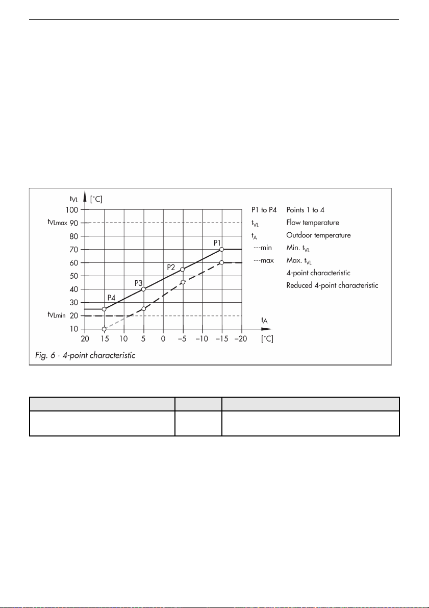
6.2.2 4-point characteristic
By means of the 4-point characteristic one can define its own heating characteristic. The
characteristic is determined by 4 points each of the outdoor temperature, the flow
temperature, the reduced flow temperature and the return flow temperature. The
parameters for maximum and minimum flow temperature limit the temperature up- and
downwards.
Functions FS Configuration
4-point characteristic
characteristic
0 CO1 -> F11 - 1
EB_37388_SOL3-7_EN001 57
Page 58

Installation and operating manual KT-Elektronik
Setting FS Parameter level / Value range
Outdoor temperature
Point 1 (P1)
Point 2 (P2)
Point 3 (P3)
Point 4 (P4)
–15 °C
–5 °C
5 °C
15 °C
PA1 / -40 to 50 °C
Flow temperature
Point 1 (P1)
Point 2 (P2)
Point 3 (P3)
Point 4 (P4)
70 °C
55 °C
40 °C
25 °C
PA1 / 5 to 130 °C
Reduced flow temp.
Point 1 (P1)
Point 2 (P2)
Point 3 (P3)
Point 4 (P4)
60 °C
40 °C
20 °C
20 °C
PA1 / 5 to 130 °C
Minimum flow temperature
PA1.06
20 °C PA1 / 5 to 130 °C
Maximum flow temperature
PA1.07
90 °C* PA1 / 5 to 130 °C
*for CO1 -> F05 -with value 1 applies to: Maximum flow temperature / 5 to 50 °C (50 °C)
6.3 3-point control
The flow temperature can be regulated by means of a PI algorithm. The valve responds to
impulses sent out by the controller in case of deviations. In particular, the length of the first
impulse depends on the size of the deviation and the boost KP (the impulse length grows
with increasing KP). The length of the impulse and the pauses in between change
continuously until the deviation is corrected. The pause duration mainly depends on the
reset time TN (pause duration increases with increasing TN). The valve transit time TY
specifies the time the valve needs to open or close from 0 to 100 %.
Functions FS Configuration
3-point control mode 1
2.0
120 s
0 s
45 s
CO1 -> F12 - 1
KP (boost) / 0.1 to 50.0
TN (reset time) / 1 to 999 s
TV (retention time) / Do not change value!
TY (valve transit time) / 5, 10, 15, , 240 s
58 EB_37388_SOL3-7_EN001
Note: The 4-point characteristic can only be activated as long as the function
adaptation is deactivated (CO1 -> F08 - 0).
Page 59

KT-Elektronik SOL3-7
6.4 Two-point control
The flow temperature can, for example, be controlled by switching a valve on and off. The
valve is turned on once the flow temperature drops T = 0,5 x differential gap below the setpoint. Once the flow temperature exceeds T = 0,5 x differential gap the valve is turned off
again. The larger the differential gap is chosen, the lower the switching frequency. By
entering a minimum running time, the valve stays on for the specified period regardless of
the flow temperature. A valve that has been turned off due to the temperature conditions
as well keeps turned off for the period entered as minimum idle time regardless of the flow
temperature.
Functions FS Configuration
3-point control mode 1
5 °C
2 min
2 min
CO1 -> F12 - 0
Differential gap / 1 to 30 °C
minimum running time / 0 to 10 min
minimum idle time / 0 to 10 min
EB_37388_SOL3-7_EN001 59
Page 60

Installation and operating manual KT-Elektronik
6.5 Underfloor heating/screed drying
By setting the function F05 to -1 in function block CO1, the associated heating circuit is
configured to work as an underfloor heating circuit. In the first place, this action only limits
the value ranges of the heating characteristic gradient and the maximum flow temperature
in level PA1:
● Value range for the gradient: 0.2 to 1.0
● Value range for the maximum flow temperature: 5 to 50 °C
Moreover, the function screed drying may be activated. The parameters displayed right
after activation of this function block are to be seen in this context. Pre-defining the screed
drying schedule: the heating up phase always starts with a temperature of 25 °C. The
temperature is then raised by the value set for the temperature increase every 24 hours – if
using the factory default settings, the flow temperature will raise to 30 °C within the first 24
hours. Once the maximum temperature has been reached, it is hold for the period of days
defined for the "maximum temperature holding days". The parameter defines the
temperature decrease schedule. By setting the temperature decrease value to zero, the
unit switches directly to "automatic operating mode" after the holding temperature phase.
The process is started by switching from STOP to START after having set the parameter
for the temperature decrease. The process can be monitored when displaying the flow
temperature ( ) of the corresponding heating circuit at information level:
Temperature raise phase
Temperature holding phase
Temperature decrease phase
If the additional symbol displayed in the flow temperature screen disappears after the last
phase, the drying process was completed successfully.
The STOP symbol indicates a flow temperature deviation of more than 5 °C over a period
of more than 30 minutes. In such cases, the process is aborted by the controller. Whilst the
STOP symbol is shown, a flow temperature of 25 °C is hold. Any power failure during the
process, or STOP indication, will reset the drying process leading to a complete restart. In
systems where the active drying process would have to be interrupted due to a domestic
water heating cycle, no storage tank charges are performed unless they act as antifreeze
charge/frost protection.
Functions FS Configuration
Underfloor heating
Screed drying
0
5 °C/24 h
45 °C
4
0 °C/24 h
STOP
CO1, 2 -> F05 - 1
Temperature increase / 1 to 10 °C/24 h
Maximum flow temperature / 25 to 60 °C
Maximum temperature holding time / 1 to 10 days
Temperature decrease / 0 to 10 °C/24 h
START
60 EB_37388_SOL3-7_EN001
Note: Accessing the function block parameters after the function has been initiated is
only possible if the function block is deactivated and reactivated again.
Attention: The function screed drying can only be used if the energy supply is
ensured for the entire duration. Auxiliary heating must be usually available.
Page 61

KT-Elektronik SOL3-7
6.6 Deactivation depending on the outdoor temperature
6.6.1 OT deactivation temperature for daytime operating mode
Once the outdoor temperature exceeds the threshold entered for the daytime operating
mode, the heating circuit to which the value applies is deactivated. The valve closes and
the pump is shut-off after t = 2 x valve closing time. When the temperature drops below the
threshold (minus a differential gap of 0.5 °C) heating is immediately resumed. If default
factory settings are used, heating is deactivated at 22 °C during the warm seasons.
Setting FS Parameter level / Value range
OT deactivation temperature for
daytime operating mode
PA1.08
22 °C PA1 / 0 to 50 °C
6.6.2 OT deactivation temperature for night-time operating mode
Once the outdoor temperature exceeds the threshold entered for the night-time operating
mode, the heating circuit to which the value applies is deactivated.
The valve closes and the pump is shut-off after t = 2 x valve closing time. When the
temperature drops below the threshold (minus a differential gap of 0.5 °C) heating is
immediately resumed. If default factory settings are used, at 15 °C outdoor temperature at
night, the system deactivates itself in order to save energy. However, when using these
settings, it should be taken into account that the system needs time in the morning to heat
up the building.
Setting FS Parameter level / Value range
OT deactivation temperature for
night-time operating mode
PA1.09
15 °C PA1 / -20 to 50 °C
6.6.3 OT activation temperature for daytime operating mode
A heating circuit working in automatic night-time operating mode is switched into daytime
operating mode automatically once the temperature drops below the OT activation
temperature. When the temperature exceeds the threshold (plus a differential gap of
0.5 °C) reduced operation is immediately resumed. This function is used to prevent an
excessive cooling of the building during periods of big freeze outside scheduled time
ranges.
Setting FS Parameter level / Value range
OT activation temperature for
daytime operating mode
PA1.10
–15 °C PA1 / –20 to 5 °C
EB_37388_SOL3-7_EN001 61
Page 62

Installation and operating manual KT-Elektronik
6.6.4 Summer operating mode (OM)
Relevant for switching into summer OM is the average temperature per day (measured and
calculated between 07:00 and 22:00 hours) during the programmed time period. Once the
calculated average OT exceeds the programmed OT for a consecutive number of days n,
the summer OM is activated the following day: the valves of all heating circuits are closed
and the circulating pumps are shut-off after t = 2 x valve closing time. Once the calculated
average OT drops below the programmed OT for a consecutive number of days n, the
summer OM is deactivated.
Functions FS Configuration
Summer operating mode (OM) 0
01.06
2
30.09
1
18 °C
CO5 -> F04 – 1
Beginning of summer period /01.01 to
31.12
Number of days needed for activation / 1
to 3
End of summer period / 01.01 to 31.12
Number of days needed for
deactivation / 1 to 3
Outside temperature threshold /0 to 30
°C
Note: The summer OM works only in automatic OM ().
6.7 Delayed outside temperature compensation
To determine the flow temperature set-point, the calculated OT is used. The temperature is
compensated with a delay at increasing and/or dropping temperatures. A sudden change
in temperature of e.g. 12 °C at a delay setting of 3 °C/h, the calculated outdoor
temperature is adjusted in small increments over a period of t = (12 °C)/(3 °C/h) = 4 hours
to meet the real outdoor temperature.
The calculated OT is shown.
Functions FS Configuration
Delayed outside temperature
compensation at dropping
temperatures
0 CO5 -> F05 - 1
Delayed outside temperature
compensation at increasing
temperatures
0 CO5 -> F06 - 1
3 °C/h Delay / 1 to 6 °C/h
62 EB_37388_SOL3-7_EN001
Note: This function can avoid a surcharge of the heating system in conjunction with
an overheating of buildings, eg during warm wind influences (Foehn) or because of a
low heating performance due to a strong solar radiation on the outdoor sensor. In the
operating level, a delayed active outdoor temperature compensation is indicated on
the display by a flashing outside temperature readout.
Page 63

KT-Elektronik SOL3-7
6.8 Remote operation
In all system variants a room temperature sensor including operating mode selector is
connectable on terminal No. 5. Other functions of the terminal like binary contacts are
deactivated in this case.
Apart from measuring the room temperature, a Room Panel (Pt 1000 sensor) provides the
selection of the following operating modes to influene the control process:
• Automatic mode
• Daytime mode
• Night-time mode
With an activated room sensor, the measured room temperature is displayed when the
remote operation is connected and activated. Nevertheless, it is not used for control unless
the Optimization, Adaptation or Flash adaptation functions have been activated.
Functions FS Configuration
Room sensor RF 0 CO1 -> F01 - 1
6.9 Optimization
A room temperature sensor is required to be able to use this function. The controller
adaptively calculates the time (maximum 8 hours) needed to preheat the reference room to
the temperature set-point for the daytime OM at the beginning of the scheduled time in
dependence on the building characteristics The system heats with the maximum flow
temperature during preheating. It is gradually built up in 10 °C increments. Weather
controlled OM takes over once the temperature set-point for the daytime OM is reached.
In dependence on the room sensor, the controller switches the heating off up to one hour
before the lapse of the scheduled time. The moment is chosen in such a way that the
temperature only drops marginally below the room temperature.
The following symbols on the screen flash during periods of preheating and early heating
shut-off respectively .
EB_37388_SOL3-7_EN001 63
Page 64

Installation and operating manual KT-Elektronik
The controller monitors the night-time set-point outside the scheduled time ranges
(reduced room temperature). Once the temperature drops below the night-time set-point,
the system heats at maximum flow temperature until the temperature set-point is exceeded
by 1 °C.
Functions FS Configuration
Room sensor RF 0 CO1 -> F01 - 1
Outdoor sensor AF 1 CO1 -> F02 - 1
Optimization 0 CO1 -> F07 - 1
Setting FS Value range
Set-point daytime OM
PA1.11
20 °C 0 to 40 °C
Set-point night-time OM
PA1.12
15 °C 0 to 40 °C
6.10 Raise return flow of external heating system
A considerable interest of solar thermal systems is
designed not with solar cash ratio of 100%, but the solar
thermal is of 'only' a secondary energy source. Hence, it
makes sense to create the possibility for the typical boiler
heating systems, to offer a heating support about a heating
circuit flow temperature increase.
6.10.1 Main principle
A boiler or an other heat source is a primary energy
source for heating circle and domestic hot water
preparation. This primary energy source works selfsufficiently, therefore the compact solar controller
SOL3-7 has no influence on their function.
The heating circuit return flow is equipped with the
sensor RüF. An switching valve RUV enables to route
the heating circuit return flow through the solar warmed
up storage tank.
The switching valve RUV becomes active if the storage
tank temperature SF1 exceeds the heating circuit return
flow temperature (RüF) at least a adjusted value return
temperature increase offset.
64 EB_37388_SOL3-7_EN001
Note: Sun exposure can lead to an increased room temperature, and thus to an early
heating shut-off. Within a short non-usage period, a drop in the room temperature can
trigger an early initiation of the preheating process targeting the daytime set-point.
Page 65

KT-Elektronik SOL3-7
If the heating circuit pump UP is active, the heating circuit return flow is warmed up, so that
less energy must be supplied by the primary energy generator.
6.10.2 Implementation
The range of the function described in chapter Temperature difference controller (page 69)
is not active after reset to factory default settings resp. Setting the system variant ID.
The return flow temperature sensor RüF is realised with the terminal number 2 which was
shown for heating circuit flow temperature sensor, because without heating circuit the
heating circuit flow temperature sensor has no function. The storage tank temperature
sensor SF1 (terminal number 7) will be used with no modification.
The switching valve RUV is realised with binary output DO 5 on terminal number 27 (UP).
On the display the switching valve RUV is shown in the control circuit 1 with the symbol
'mixing valve up' , not as a heating circuit circulation pump.
In the settings level CO3 is to adjust the return flow temperature increase offset as
Temperature difference set point. The hysteresis is fixed to +/- 2 K and is not adjustable.
The functionality raise return flow is not prevented about usage schedule, summer
operating mode or other functions.
The state of the binary output to control the switching valve RUV (named TdS) can be
changed in the manual operating mode.
Functions FS Configuration
Temperature difference control
(TDR)
0 CO3 -> F10 – 0 Off (1 On)
Function block parameter FS Range
Temperature difference set point 10K -30...+160 °C
Reference input 2 Terminal number 1...9
Controlled input 7 Terminal number 1...9
EB_37388_SOL3-7_EN001 65
Page 66

Installation and operating manual KT-Elektronik
7 Domestic water circuit functions
7.1 Domestic water heating in storage tank
The domestic water circuit allows setting the desired temperature the water should be
heated up to by means of auxiliary heating.
Setting FS Parameter level / Value range
Set-point domestic water
Daytime Operation
PA4.01
45 °C PA4 / 5 to 90 °C
Set-point domestic water
Night-time operation
PA4.02
10 °C PA4 / 5 to 90 °C
Differential gap
PA4.03
5 K PA4 / 0 to 30 K
Temperature difference to delay auxilary
heating when collector pump is active
PA4.04
0 K 0 to 20 K
7.2 Thermal Disinfection of the storage tank
A usage schedule is used in systems with domestic water heating to perform a thermal
disinfection in order to reduce the Legionella risk. The storage tank with storage sensor
SF1 is heated up to defined the Disinfection temperature. The process begins at the
programmed time Start time and ends not later than the programmed Stop time.
In systems with solar domestic water heating, thermal disinfection is performed outside
scheduled time ranges depending on the solar gain. The controller monitors the storage
temperatures and disinfection intervals in order to reduce the consumption of additional
energy (auxiliary heating).
Too high temperatures due to thermal disinfection may cause limescale that can negatively
affect the performance of the heat exchanger.
Function FS Description
Thermal disinfection
Day of week
Start time
Stop time
Disinfection temperature
0
1
00:00
00:00
70 °C
CO4 -> F14- 1 - Thermal disinfection
Actuation day(-s) / 1...7 or 1-7 (1..Monday,...)
Beginning of thermal disinfection
End of thermal disinfection
Min. storage temperature for thermal disinfection /
50 to 90 °C
66 EB_37388_SOL3-7_EN001
Page 67

KT-Elektronik SOL3-7
8 System wide functions - all system variants
8.1 Automatic summer/winter switching
Switching is done automatically on the last Sunday in March at 2:00 am and on the last
Sunday in October at 3:00 am.
Functions FS Configuration
Summer/winter switching 1 CO5 -> F08 - 1
8.2 Antifreeze
Antifreeze measures become effective once the outdoor temperature drops below the
programmed temperature threshold. The differential gap to deactivate the antifreeze
measures is 1°C.
I. Antifreeze program I (reduced antifreeze): Antifreeze measures are only initiated if all
heating circuits are running in stand-by mode. All circulation pumps are turned on by
force and their flow temperature is set to 10°C. The circulation pump for the domestic
water circuit is only turned on by force if the rotary switch is positioned at stand-by
mode for all heating circuits. However, the storage tank is always recharged to 10°C in
cases where the storage tank temperature drops below 5°C.
II. Antifreeze program II: The circulation pumps for the heating circuits are generally turned
on by force. The flow temperature set-points of all heating circuits in holding operating
mode or stand-by mode are set to +10 °C. The circulation pump for the domestic water
circuit is generally turned on. If the storage tank temperature drops below +5 °C, the
storage tank is recharged to +10 °C.
Functions FS Configuration
Antifreeze program I
3 °C
CO5 -> F09 - 0
Antifreeze threshold/ –15 to 3 °C
Antifreeze program II
3 °C
CO5 -> F09 - 1
Antifreeze threshold/ –15 to 3 °C
Minimum temperature of storage
tank
10 °C
EB_37388_SOL3-7_EN001 67
Note: Antifreeze mode for a pump, a heating circuit or a domestic water circuit is only
active if the antifreeze symbol is shown in the display. Antifreeze monitoring is
deactivated in stand-by mode in systems with fixed value control without outdoor
sensor.
Page 68

Installation and operating manual KT-Elektronik
8.3 Locking manual operating mode
This function can be used to lock the manual operating mode in order to protect the
heating system. When activated, the system is run in automatic mode when the rotary
switch is positioned at .
Functions FS Configuration
Locking manual operating mode 0 CO5 -> F21 - 1
8.4 Locking the rotary switch
When activated, the system is run in automatic mode regardless of the rotary switch
position. No further settings can be programmed using the rotary switch.
Functions FS Configuration
Locking the rotary switches 0 CO5 -> F22 - 1
8.5 Enter a valid individual access code
The standard access code can be replaced by an individual code to prevent unauthorized
function or parameter changes. The individual code can be selected from 0100 to 1900.
Procedure:
Switch to configuration and settings level.
Enter access code 1995 (key number).
Confirm access code 1995.
Display: 1900 (Number is not inverted, but provided to edit)
Enter the current valid access code.
Confirm code.
Display: Current, even confirmed access code (inverted)
Edit individual code.
Confirm entered individual code.
The new valid access code is from now on the one confirmed.
Move the rotary switch back to the "Information level" position (left hand).
68 EB_37388_SOL3-7_EN001
Page 69

KT-Elektronik SOL3-7
8.6 Temperature difference controller
To applicate a raise return flow temperature of a seperate heating circuit, to realize tank-totank transfer or to charge or discharge of heating energy there is designed one additional
temperture diffrence controller inside.
The temperature sensors used for this function may be used additionally to the defined
function in the chosen system variant (example: storage tank temperature sensors SF1
and SF2).
The relay output is fixed to terminal number 27 (UP). This define requires that the
additionally temperature difference controller is not available in system variants including
heating circuit.
Settings
Functions FS Configuration
Temperature difference control
(TDR)
0 CO3 -> F10 – 0 Off (1 On)
Function block parameter FS Range
Temperature difference set point 10K -30...+160 °C
Reference input 2 Terminal number 1...9
Controlled input 7 Terminal number 1...9
The facrory default setting of these parameteres is designated to use raise return flow
temperature of a seperate heating circuit.
Function
The switching relay output terminal number 27 (UP) becomes active, if the difference of
reference input and controlled input exeeds the temperature difference set point.
The switching relay output terminal number 27 (UP) becomes inactive, if the difference of
reference input and controlled input falls below the temperature difference set point.
The hysteresis is fixed to +/- 2 Kelvin.
In the information level sensors (reference input and controlled input) where shown
each with the terminal defined symbols. The switching output visualizes the symbol
(responsible für circuit 1 mixing valve up signal).
In “Manual operating mode” the switching output may be modified when shown the
indication 'TdS'.
EB_37388_SOL3-7_EN001 69
Page 70

Installation and operating manual KT-Elektronik
9 Malfunction
A system malfunction is immediately shown on the display by a overlapping frame on
system scheme.
The error level including detailed messages is opened by pressing the rotary pushbutton. A
larger number of error messages might eventually be retrieved by turning the rotary
pushbutton. Error messages for critical malfunctions are kept in the display loop even if the
details are not opened by pressing the rotary pushbutton.
The display is illuminated for one second in intervals of about 10 seconds for the time of
system malfunction
At error level, the error messages are displayed according to the following list.
9.1 Error list
Error 1 = sensor failure (chapter 9.2)
Error 4 = maximum charge temperature reached
Error 6 = temperature monitoring alarm(chapter 9.3)
Error 7 = unauthorized access captured (chapter 9.3)
9.2 Sensor failure
According to the error list, sensor failures are indicated by
the message "Err 1" at error level. Detailed informations
can be retrieved at information level by querying the
temperature values. Each sensor icon combined with three
small horizontal bars instead of a temperature value
indicate a faulty sensor. The following list describes how
the controller behaves in case of a sensor failure for each
single sensor.
Outdoor sensor AF: If an outdoor sensor fails, the system is run with value of
PA1.07 (maximum flow temperature set-point ), else, if not set or greater than 50
°C, with 50 °C.
Flow sensor, heating circuit: If a flow sensor in the heating circuit fails, the related
valve is opened to 30 %.
70 EB_37388_SOL3-7_EN001
Note: After a system variant ID change, eventual error messages are suppressed for
around three minutes after the change.
Page 71

KT-Elektronik SOL3-7
Flow sensor, solar circuit: If a primary flow sensor fails, the domestic water is not
heated up any more.
Storage sensor SF1/2: If one of these sensors fails, the buffer storage is not charged
any more.
9.3 Temperature monitoring
If the temperature in one of the control circuits deviates more than 50 K from normal for a
period of 30 minutes, the error message "Err 6" is generated (temperature monitoring
alarm).
Functions FS Configuration
Temperature monitoring 0 CO5 -> F19 - 1
9.4 Error status register
The error status register is used to report controller or system failures. In modem operating
mode with error reporting function, each change of error status triggers a dial up
connection to the building control system (BCS) to report the status change. The errors
that should affect the error status register can be set after having entered the access code
0025.
The default factory setting „465“ causes that only the error messages in bold in the
following table affect the error status register.
Another example shows the value to be set for the change detection for sensor failure
alarm and temperature monitoring.
Error message Description Decimal value FS Example
Error 1 Sensor failure 1 1 1
Error 2 - 2
Error 3 - 4
Error 4 Max. charging temperature reached 8
Error 5 16 16
Error 6 Temperature monitoring alarm 32 32
Error 7 Unauthorized access 64 64
Error 8 - 128 128
Error 9 - 256 256
Sum Sum
Factory default setting, access code 0025 = 465
Example: Error status register if sensor failure and alarm = 33
EB_37388_SOL3-7_EN001 71
Page 72

Installation and operating manual KT-Elektronik
9.5 SMS delivery in case of a system failure
If a dial up modem is connected to the KOM232M (Mat-No. 11988) communication module
(chapter 10.3), the controller is able to send error messages to a cell phone. An SMS is
sent as soon as a failure is captured in the error status register. The message looks like
this on the display of the cell phone:
[Date] [Time]
[Call no. of the controller]
Reglerstörung (Controller failure)
SOL3 # [Controller ID]
The time stamp [Date], [Time] is generated by the SMS provider rather than by the
controller. A detailed error message is not available.
If Modbus and modem error reporting are active at the same time, the connection to the
BCS is built up in the first place followed by the SMS delivery. If the connection to the BCS
fails, the system attempts to build it up for the programmed number of times.
The providers SMS service numbers (TAPnr) in Germany at the time of writing are:
D1: 0171 252 1002 (0171 252 1099 alternatively available)
E-Plus: 0177 1167
Cellnet (UK): 0044 786 098 0480 – mobile comm. network of D1, D2, O2 and E-Plus
0 respectively the pre dial number has to be prepended in telephone installations with
secondary structure. The subscriber number (HAndi) has to be entered as follows: 49 xxx
yyyyyy, with xxx for 160, 171 or other valid network prefix and yyyyyy for the specific
recipient number.
Functions FS Configuration
SMS 0 CO6 -> F08 – 1
Modem function 0 CO6 -> F03 – 1
Automatic modem configuration 0 CO6 -> F04 – 1
Parameter* FS Parameter level / Value range
Modem dialling pause (P)
PA6.04
5 min PA6 / 0 to 255 min
Modem time out (T)
PA6.05
5 min PA6 / 0 to 255 min
Number of dial attempts (C)
PA6.06
15 PA6 / 0 to 255
SMS service numbers (TAPnr)
PA6.07
- PA6 / max 22 digits; 1, 2, 3, ..., 9, 0;
„-“ End of string; „P“ Pause
Cell phone number (HAndi)
PA6.08
- PA6 / max 22 digits; 1, 2, 3, ..., 9, 0;
„-“ End of string; „P“ Pause
* chapter 10.8 („ Description of the adjustable communication settings“)
72 EB_37388_SOL3-7_EN001
Note: The controller ID is shown as the first value in the advanced information level
under Info 2 (chapter 1.10).
Page 73
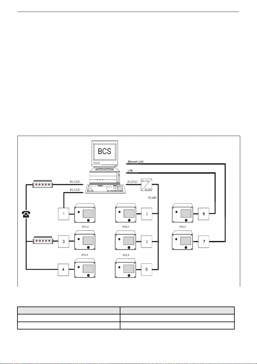
KT-Elektronik SOL3-7
10 Communication
The heat pump controller SOL3-7 can be connected to a building control system via an
optional communication module. A suitable software allows to set up a complete building
control system for process visualization and communication.
The following communication variants are available:
• Operation with USB connection with communication module USB-L3 (6)
• Operation with LAN connection with Modbus-TCP-Gateway (7)
• Operation with dial up modem with communication module KOM232M (3)
• Operation with dial up modem DataMod11 (4)
An automatic communication is basically only initiated in case of failures. The controller
operates in an autonomous way, but can be contacted, read out and adjusted at any time
via modem.
• 2-wire bus operation with communication module iCon485 (2)
or Modbus-MBus-Gateway (5)
• RS-232 connection operation with communication module KOM232PC (1)
All communication modules are designed for operation at the communication interface. The
interface properties are not configurable.
Property Setting
Baudrate 19200 Baud
Data bit, Parity, Stop bit 8 Bit, no, 1 Stop bit
EB_37388_SOL3-7_EN001 73
Page 74

Installation and operating manual KT-Elektronik
10.1 Communication module KOM232PC
The connector for the optional communication module (Mat-No. 11988) is located on the
left side (front panel view) inside the controller housing (RJ45 connector). The operation of
the controller in conjunction with the communication module KOM232PC requires the use
of appropriate communication tools (software).
Wiring diagram for communication module KOM232PC
10.2 Communication module iCon485
The connector for the optional communication module iCon485 (Mat-No. 11994) is located
on the left side (front panel view) inside the controller housing (RJ45 connector). The
operation of the controller in conjunction with the communication module iCon485 requires
a permanent bus connection (data cable).
Each controller and control unit is wired to an open token ring. The end of the wire is
connected to the building control system via an RS-485/RS-232 converter (e.g. CoRe01).
The bus connection range (cable length) is limited to a maximum of 1200 m. A maximum of
126 devices can be connected to such a segment. In segments with a longer distance
(> 1200m) or in segments with more than 126 devices, repeater have to be installed to
maintain the signal strength (e.g. CoRe01). On a bus with 8-bit addressing, a maximum of
246 devices can be connected and addressed.
In times where the communication between the building control system and controller is
interrupted, interventions of the building control system into dynamic processes can be
influenced with the function building control system monitoring for a limited period of
time.
As long as valid Modbus queries are captured, the controller resets the time monitoring;
but after a lapse of 30 minutes all collective level bits are reinitialized to "autonomous".
74 EB_37388_SOL3-7_EN001
Page 75

KT-Elektronik SOL3-7
Functions FS Configuration
Modbus 1 CO6 -> F01 – 1
Modbus with 16-bit addressing 0 CO6 -> F02 – 1
Modem function 0 CO6 -> F03 – 1
Automatic modem configuration 0 CO6 -> F04 - 1
Blocking the BCS dial up 0 CO6 -> F05
BCS dial up on corrected failures 0 CO6 -> F06
Control system monitoring 0 CO6 -> F07 – 0
Setting FS Parameter level / Value range
Station address (ST)
PA6.01 bzw. PA6.02
255 PA6 / 1 to 247
with CO6 -> F02 - 1: 1 to 32000
Wiring diagram for communication module iCon485
EB_37388_SOL3-7_EN001 75
ATTENTION!
When installing, the relevant standards and regulations related to lightning protection
and over-voltage/voltage surge protection have to be attended to.
Page 76

Installation and operating manual KT-Elektronik
10.3 Communication module KOM232M
The connector for the optional communication module KOM232M (Mat-No. 11989) is
located on the left side (front panel view) inside the controller housing (RJ45 connector).
The communication module KOM232M allows the connection of a dial up modem to the
controller.
A dial up modem is required when connecting the controller to the telecommunication
network. This way, the controller operates autonomously and is enabled to send a call to
the building control system (BCS) in case of failures. Additionally, the BCS can call the
controller to read it out and to send new data providing the valid access code after having
written the holding register No. 40145.
The function modem dial up blocking can be selected in special cases in order to
suppress dial ups to report failures. With the function modem dial up on corrected
failures the BCS is additionally informed if a previously reported failure no longer exists.
By using the automatic modem configuration function, the modem connected to the
controller needs no further configuration; this is done automatically by the controller.
Functions FS Configuration
Modbus 1 CO6 -> F01 – 1
Modbus with 16-bit addressing 0 CO6 -> F02 – 1
Modem function 0 CO6 -> F03 – 1
Automatic modem configuration 0 CO6 -> F04 - 1
Blocking the BCS dial up 0 CO6 -> F05
BCS dial up on corrected failures 0 CO6 -> F06
Control system monitoring 0 CO6 -> F07 – 0
Setting FS Parameter level / Value range
Station address (ST)
PA6.01 bzw. PA6.02
255 PA6 / 1 to 247
with CO6 -> F02 - 1: 1 to 32000
Modem dialling pause (P)
PA6.02
5 min PA6 / 0 to 255 min
Modem time out (T)
PA6.02
5 min PA6 / 0 to 255 min
Number of dial attempts (C)
PA6.02
15 PA6 / 1 to 255
Phone number of the BCS (TELnr)
PA6.02
- PA6 / max 22 digits; 1, 2, 3, ..., 9, 0;
„-“ End of string; „P“ Pause
76 EB_37388_SOL3-7_EN001
Note: Once the holding register No. 40145 has been written for three consecutive times
accessed with an invalid code, the controller cuts the modem connection immediately
and generates an error message "Err 7" (Unauthorized access). Therewith a call to the
configured building control system as well as an SMS delivery are triggered. Bit D6 is
deleted as soon as the error status register is read out by the building control system
and the connection is terminated.
Page 77

KT-Elektronik SOL3-7
Wiring diagram for communication module KOM232M
10.4 Data Modem DataMod11
The connector for the optional data modem DataMod11 (Mat-No. 11991) is located on
the left side (front panel view) inside the controller housing (RJ45 connector). Settings and
notes from chapter 10.3 remain valid.
Wiring diagram for DataMod11
EB_37388_SOL3-7_EN001 77
Page 78

Installation and operating manual KT-Elektronik
10.5 ModBus-MBus-Gateway
The connector for the optional ModBus-MBus-Gateway (Mat-No. 11997) is located on the
left side (front panel view) inside the controller housing (RJ45 connector). The operation of
the controller in conjunction with the ModBus-MBus-Gateway requires a permanent bus
connection (data cable).
The ModBus-MBus-Gateway is used to integrate M-Bus meters into building control
systems of HVAC system networks. The ModBus-MBus-Gateway allows an easy to handle
connection of heat, electricity or water flow meters. Up to 6 meter according to EN 1434-3
can be connected.
Settings and notes from chapter 10.2 remain valid.
Wiring diagram for ModBus-MBus-Gateway
78 EB_37388_SOL3-7_EN001
Page 79

KT-Elektronik SOL3-7
10.6 USB communication cable USB-L3
The connector for the USB communication line L3 USB (Material No.: 11982) is located on
the left side (front panel view) inside the controller housing (RJ45 connector). The
operation of the controller in conjunction with the USB communication cable USB-L3
requires the use of appropriate communication tools (software) and installing a device
driver to provide a "COM port" in advance.
Wiring diagram for USB communication cable UBS-L3
EB_37388_SOL3-7_EN001 79
Page 80

Installation and operating manual KT-Elektronik
10.7 Modbus-TCP-Gateway
The connector for the optional ModBus-TCP-Gateway (Mat-No. 11993) is located on the
left side (front panel view) inside the controller housing (RJ45 connector). The operation of
the controller in conjunction with the ModBus-TCP-Gateway requires the use of
appropriate communication tools (software).
The Modbus-TCP-Gateway extends a SOL3-7 to an Ethernet (LAN) interface. All Modbus
RTU commands the controller support are available via Modbus TCP.
Wiring diagram for Modbus-TCP-Gateway
10.8 Description of the adjustable communication settings
Station address (ST)
This address is used to identify the controller in bus or modem operating mode. Each
address must be assigned only once within a system.
Cyclical initialization (I)
This parameter specifies the time for a cyclical issue of initialization commands "ATZ". The
command is not issued when made a call or there is a connection. The initialization "ATZ"
causes the modem to copy the profile 0 in the active profile. This assumes that the
adjustment of modem parameters and storing the same is done in the modem profile 0 by
a suitable terminal program. With CO6 -> F04 - 1 eliminates this type of modem
initialization.
Modem dialling pause (P)
A dialling pause (approx 3 to 5 minutes) should be kept within two BCS/SMS provider calls
in order not to permanently stress the telecommunication network. The modem dialling
pause is programmed as period between two dial attempts.
80 EB_37388_SOL3-7_EN001
Page 81

KT-Elektronik SOL3-7
Modem time out (T)
If connected to the BCS, but not addressing a Modbus data point, the controller closes the
connection after the modem has timed out. If the error status register has not been read
out during the connection to the BCS, the controller attempts to reconnect to the BCS after
the programmed modem dialling pause (P) to repeat the procedure. The time setting is
irrelevant for SMS delivery.
Number of dial attempts (C)
The dial attempts are repeated in compliance with the modem dialling pause as long as the
BCS/SMS service centre line is occupied respectively the call initiation has not been reset
by the building control system. Unsuccessful connection attempts are indicated by "OFF"
at the advanced information level. The dialling attempts counter is automatically reset at
12:00 followed by new attempts.
Resetting the call initiation = reading out the error status register (HR40150)
Phone number of the BCS (TELnr)
The phone number of the building control system, including area code – if needed – has to
be entered here. Short dialling breaks can be provided by entering a "P", where each P
equals 1 second, the end of the dialling string has to be indicated by entering „–“. The
phone number can be up to 22 characters long.
Example phone number „069, 2 seconds break, 4009, 1 second break, 0“:
0 6 9 P P 4 0 0 9 P 0 – (= 11 characters)
10.9 Memory module
The memory module ParaMem (Mat-No. 17090) is especially suitable to transfer all
programmed data from one SOL3 controller to several other SOL3 controller. The
connector for the memory module is located on the left side (front panel view) inside the
controller housing (RJ45 connector). If successfully plugged in, “S3 SP” will be displayed
on the screen of the controller. If the memory module already contains data from another
SOL3 controller, they can be accessed by turning the rotary pushbutton to "SP S3".
By pressing the rotary pushbutton in "S3 SP" position, the current controller settings
are copied to the module.
By pressing the rotary pushbutton in "SP S3" position, the current module data is
copied to the controller and the display of "LESE".
The displayed bar graph is used as progress bar during the transfer. "I.O." is displayed to
confirm the completion of a successful data transfer. The memory module can now be
disconnected by unplugging it.
EB_37388_SOL3-7_EN001 81
Note: By activating the function block CO6 -> F04 - 1, the connected modem is
configured automatically.
Page 82

Installation and operating manual KT-Elektronik
10.10 55Viewer for visualization and remote maintenance.
The software 55Viewer (Mat-No. 37160) is available to visualize and remote maintain the
system.
The software allows to display a graphical representation of the complete system
installation with all sensor data and all switching states of the pump and valve outlets.
Various tabs are available to display all controller settings and data, programmed
schedules and heat meter data. 55Viewer also allows to modify controller parameters.
A personal computer with the following minimum requirements is needed:
• PC with a Pentium II processor or equivalent CPU (300 MHz or higher, 500 MHz
or more are recommended)
• Serial port respectively an appropriate modem for dial up connections
• SVGA graphics card (min. resolution 800x600)
• CD-ROM drive
• Min 64 MB of RAM (recommended 128 MB)
• Min 150 MB of free hard disk space
• One of Windows 2000, XP, Vista or Windows 7 as OS
82 EB_37388_SOL3-7_EN001
Page 83

KT-Elektronik SOL3-7
10.11 Data Logging
The data logging module DataMem (Mat-No. 37699) allows saving the following controller
data in two minute intervals:
Sensor readings
Control signals [%]
Switching states of the pump outlets
Error status register and archive
Access to controller settings
The connector for the memory module is located on the left side (front panel view) inside
the controller housing (RJ45 connector).
Once the memory chip of the data logging module is full, approx. after 8 days, the module
starts overwriting the oldest data. The current memory capacity can be viewed in the
advanced information level, it is the second value displayed (range: 0 to 6035) in menu
item "Info 2" (chapter 1.10). After plugging in the data logging module, the value is not
displayed before the first scanning cycle is complete.
The saving cycle interval in minutes, range from 1 to 99 minutes, can be programmed after
entering the access code 0010. The default factory setting of 2 corresponds to a two
minute cycle interval.
The data can be analysed using the PC based software "Data Logging Viewer". The USB
converter 3 (Mat-No. 11995) which is shipped with the viewer software is required to
connect the logging module to a PC.
A device description file is also required to display the data correctly.
EB_37388_SOL3-7_EN001 83
Page 84

Installation and operating manual KT-Elektronik
11 Mounting
The device consists of a controller housing containing the electronics assembly and a
mounting panel with the terminal strips. It is suited for control panel, wall and DIN rail
mounting (Figure 13).
Control panel mounting
1.Loose both screws (1).
2.Separate housing and mounting panel.
3.Cut out a rectangle of 138 by 92 mm (W x H) from the panel.
4.Insert the housing into the cut-out.
5.Use the screws (2) to fix the housing onto the panel.
6.Perform electrical connection according to chapter 12.
7.Remount housing.
8.Tighten both screws (1).
Wall mounting
1.Loose both screws (1).
2.Separate housing and mounting panel.
3.Eventually drill holes at the predefined positions with the given dimensions. Fix
mounting panel with 4 screws.
4.Perform electrical connection according to chapter 12.
5.Remount housing.
6.Tighten both screws (1).
DIN rail mounting
1.Hook the spring-loaded hooks (4) to the bottom of the DIN rail (3).
2.Slightly push up the housing and pull the upper clips over the rail.
3.Loose both screws (1).
4.Separate housing and mounting panel.
5.Perform electrical connection according to chapter 12.
6.Remount housing.
7.Tighten both screws (1).
84 EB_37388_SOL3-7_EN001
Page 85

KT-Elektronik SOL3-7
Figure 12 - Mounting
EB_37388_SOL3-7_EN001 85
Page 86

Installation and operating manual KT-Elektronik
12 Electrical connection
ATTENTION!
VDE and utility specifications and regulations have to be attended to when
wiring and connecting the controller. Therefore, this task has to be performed
by qualified personnel only!
12.1 Notes for wire installation
230 V-supply lines and signal lines must be routed in separate cables! To increase
noise resistance, a minimum distance of 10 cm between each cable has to be kept!
This spatial separation has to be considered also in control cabinets!
The cables for digital signals (bus lines) and analogue signal lines (sensor lines,
analogue outputs) must also be routed in separate cables!
It is recommended to use shielded cables for analogue signal lines in systems with
high electromagnetic noise level. The shield is to be single-earthed either at input or
output of the cabinet with a large area contact! The central earthing point is to be
connected to the protective earth conductor PE with the shortest possible cable (>= 10
mm² in diameter)!
Inductances in the cabinet, like contactor coils, are to be supplied with appropriate
snubber circuits (RC snubber)!
High field strength cabinet components like transformers and frequency inverters
should be shielded by separating plates with good earthing.
12.2 Surge Protection Measures
Signal lines routed outdoor or over long distances should be surge protected! For
bus lines, such measures are essential.
The shielding of signal lines laid outdoor must be conductive and double-earthed.
The surge arrester has to be connected to the input of the control cabinet.
12.3 Connecting the controller
The connection is performed according to the following wiring diagram. The housing has to
be opened to connect the cables. The housing has marked feedthroughs on the upper or
lower side or on the mounting panel that have to be broke through and then supplied with
the appropriate grommets respectively screwing.
86 EB_37388_SOL3-7_EN001
Page 87

KT-Elektronik SOL3-7
12.3.1 Connecting the sensors
Wires with a minimum diameter of 2 by 0.5 mm² may be connected to the terminal strips on
the mounting panel.
Connecting the actuators
3-point-/2-point duty outputs: moisture proof cables with a minimum diameter of 1.5 mm²
are to be connected to the terminals of the controller output. It is recommended to check
the direction of rotation at start-up time.
12.3.2 Connecting the pumps
All wires with a minimum diameter of 1.5 mm² are to be connected to the controller
according the wiring diagram. The relay outputs are isolated/potential-free contactors, thus
not supplied with power from the controller. Therefore, the terminals 20, 22 and 25 – and
eventually 28 have to be connected to L1 (terminal 18).
12.3.3 Legend for connection diagram
VF Flow sensor (heating circuit) CP Collector pump
RF Room sensor SP Storage (charging) pump
AF Outdoor sensor CUV Collector switching valve
CRF Collector return-flow sensor SUV Storage switching valve
CVF Collector flow sensor RUV Return flow switching valve
SF Storage sensor CTP Collector exchanger pump
CF Collector sensor NH Auxiliary heating
VST-Imp. Volume flow impulses M+/M- Control signal for heating circuit
mixing valve
ZP Domestic water-
circulation pump
flow 0..10V output for
pump rotation speed
EB_37388_SOL3-7_EN001 87
Note: The motor actuators are not automatically supplied with power from the
controller. They can be connected to an external power source via terminal 28. If this is
not desired, jumper have to be set from terminal 18 to 28.
Page 88

Installation and operating manual KT-Elektronik
12.3.4 Wiring diagram
Note: The diagram shown on the back of the controller housing applies to most of the
possible system variants. Certain system variant configuration require a different usage of
single relay outputs. The following table shows the assignment of functions to terminals for
all system variants.
88 EB_37388_SOL3-7_EN001
Page 89

KT-Elektronik SOL3-7
12.3.5 Terminal assignment for Outputs
System variant
T. 21
T. 23
T. 24
T. 26
T. 27
T. 29
T. 30
I - I.0.0
CP1
I - I.0. I
CP1UPM-
M+
I - I. I.0
CP1
NH
I - I. I. I
CP1NHUPM-M+
I - I.2.0
CP1
ZP
I - I.2. I
CP1ZPUPM-M+
I - I.3.0
CP1ZPNH
I - I.3. I
CP1ZPNHUPM-
M+
I - 2.0.0
CP1
SUV
I - 2.0. I
CP1
SUVUPM-
M+
I - 2. I.0
CP1
SUV
NH
I - 2. I. I
CP1NHSUVUPM-
M+
I - 2.2.0
CP1
SUV
ZP
I - 2.2. I
CP1ZPSUVUPM-
M+
I – 2.3.0
CP1
SUVZPNH
I – 2.3. I
CP1ZPNH
SUVUPM-
M+
I - 3.0.0
SP1
SP2
I - 3.0. I
SP1
SP2UPM-
M+
I - 3. I.0
SP1
SP2
NH
I - 3. I. I
NH
SP1
SP2UPM-
M+
I - 3.2.0
SP1
SP2
ZP
I - 3.2. I
ZP
SP1
SP2UPM-
M+
I – 3.3.0
SP1
SP2ZPNH
I – 3.3. I
ZPNHSP1
SP2UPM-
M+
I o I.0.0
CP1
CTP
I o I.0. I
CP1
CTPUPM-
M+
I o I. I.0
CP1
CTP
NH
I o I. I. I
CP1
CTPNHUPM-M+
I o I.2.0
CP1
CTP
ZP
I o I.2. I
CP1ZPCTPUPM-
M+
I o I.3.0
CP1
CTPZPNH
I o I.3. I
CP1ZPCTPNHUPM-M+
I o 2.0.0
CP1
CTP
SUV
I o 2.0. I
CP1
CTP
SUVUPM-
M+
I o 2. I.0
CP1
CTP
SUV
NH
EB_37388_SOL3-7_EN001 89
Page 90

Installation and operating manual KT-Elektronik
System variant
T. 21
T. 23
T. 24
T. 26
T. 27
T. 29
T. 30
I o 2. I. I
CP1NHCTP
SUVUPM-
M+
I o 2.2.0
CP1
CTP
SUV
ZP
I o 2.2. I
CP1ZPCTP
SUVUPM-
M+
I o 2.30
CP1
CTP
SUVZPNH
I o 3.0.0
CP1
SP1
SP2
I o 3.0. I
CP1
SP1
SP2UPM-
M+
I o 3. I.0
CP1
SP1
SP2
NH
I o 3. I. I
CP1NHSP1
SP2UPM-
M+
I o 3.2.0
CP1
SP1
SP2
ZP
I o 3.2. I
CP1ZPSP1
SP2UPM-
M+
I o 3.3.0
CP1
SP1
SP2ZPNH
2 - I.0.0
CP1
CUV
2 - I.0. I
CP1
CUVUPM-
M+
2 - I. I.0
CP1
CUV
NH
2 - I. I. I
CP1
CUVNHUPM-M+
2 - I.2.0
CP1
CUV
ZP
2 - I.2. I
CP1
CUVZPUPM-M+
2 - I.3.0
CP1
CUVZPNH
2 - I.3. I
CP1
CUVZPNHUPM-
M+
2 - 2.0.0
CP1
CUV
SUV
2 - 2.0. I
CP1
CUV
SUVUPM-
M+
2 - 2. I.0
CP1
CUV
SUV
NH
2 - 2. I. I
CP1
CUVNHSUVUPM-
M+
2 - 2.2.0
CP1
CUV
SUV
ZP
2 - 2.2. I
CP1
CUVZPSUVUPM-
M+
2 – 2.3.0
CP1
CUV
SUVZPNH
2 - 3.0.0
CUV
SP1
SP2
2 - 3.0. I
CUV
SP1
SP2UPM-
M+
2 - 3. I.0
CUV
SP1
SP2
NH
2 - 3. I. I
NH
CUV
SP1
SP2UPM-
M+
2 - 3.2.0
CUV
SP1
SP2
ZP
2 - 3.2. I
ZP
CUV
SP1
SP2UPM-
M+
2 – 3.3.0
CUV
SP1
SP2ZPNH
2 o I.0.0
CP1
CUV
CTP
2 o I.0. I
CP1
CUV
CTPUPM-
M+
2 o I. I.0
CP1
CUV
CTP
NH
2 o I. I. I
CP1
CUV
CTPNHUPM-M+
90 EB_37388_SOL3-7_EN001
Page 91

KT-Elektronik SOL3-7
System variant
T. 21
T. 23
T. 24
T. 26
T. 27
T. 29
T. 30
2 o I.2.0
CP1
CUV
CTP
ZP
2 o I.2. I
CP1
CUV
CTPZPUPM-M+
2 o I.3.0
CP1
CUV
CTPZPNH
2 o 2.0.0
CP1
CUV
CTP
SUV
2 o 2.0. I
CP1
CUV
CTP
SUVUPM-
M+
2 o 2. I.0
CP1
CUV
CTP
SUV
NH
2 o 2.2.0
CP1
CUV
CTP
SUV
ZP
2 o 2.3.0
CP1
CUV
CTP
SUVZPNH
2 o 3.0.0
CP1
CUV
SP1
SP2
2 o 3.0. I
CP1
CUV
SP1
SP2UPM-
M+
2 o 3. I.0
CP1
CUV
SP1
SP2
NH
2 o 3.2.0
CP1
CUV
SP1
SP2
ZP
2 o 3.3.0
CP1
CUV
SP1
SP2ZPNH
3 - I.0.0
CP1
CP2
3 - I.0. I
CP1
CP2UPM-
M+
3 - I. I.0
CP1
CP2
NH
3 - I. I. I
CP1
CP2NHUPM-M+
3 - I.2.0
CP1
CP2
ZP
3 - I.2. I
CP1
CP2ZPUPM-M+
3 - I.3.0
CP1
CP2ZPNH
3 - I.3. I
CP1
CP2ZPNHUPM-
M+
3 - 2.0.0
CP1
CP2
SUV
3 - 2.0. I
CP1
CP2
SUVUPM-
M+
3 - 2. I.0
CP1
CP2
SUV
NH
3 - 2. I. I
CP1
CP2NHSUVUPM-
M+
3 - 2.2.0
CP1
CP2
SUV
ZP
3 - 2.2. I
CP1
CP2ZPSUVUPM-
M+
3 – 2.3.0
CP1
CP2
SUVZPNH
3 o I.0.0
CP1
CP2
CTP
3 o I.0. I
CP1
CP2
CTPUPM-
M+
3 o I. I.0
CP1
CP2
CTP
NH
3 o I. I. I
CP1
CP2
CTPNHUPM-M+
3 o I.2.0
CP1
CP2
CTP
ZP
3 o I.2. I
CP1
CP2
CTPZPUPM-M+
3 o I.3.0
CP1
CP2
CTPZPNH
3 o 2.0.0
CP1
CP2
CTP
SUV
3 o 2.0. I
CP1
CP2
CTP
SUVUPM-
M+
EB_37388_SOL3-7_EN001 91
Page 92

Installation and operating manual KT-Elektronik
System variant
T. 21
T. 23
T. 24
T. 26
T. 27
T. 29
T. 30
3 o 2. I.0
CP1
CP2
CTP
SUV
NH
3 o 2.2.0
CP1
CP2
CTP
SUV
ZP
3 o 2.3.0
CP1
CP2
CTP
SUVZPNH
3 o 3.0.0
CP1
CP2
SP1
SP2
3 o 3.0. I
CP1
CP2
SP1
SP2UPM-
M+
3 o 3. I.0
CP1
CP2
SP1
SP2
NH
3 o 3.2.0
CP1
CP2
SP1
SP2
ZP
3 o 3.3.0
CP1
CP2
SP1
SP2ZPNH
12.3.6 Terminal assignment for inputs
The assignments shown in the wiring diagram on page 88 applies to all system variants.
Not required sensors don't need to be connected.
Inputs that are not required by the particular system variant may be connected, and
information may be displayed at extended information level (chapter 1.10). This allows
displaying temperature data of other sensors for information purposes, like flow and return
flow temperature of an attached wood-fired boiler and other.
92 EB_37388_SOL3-7_EN001
Page 93

KT-Elektronik SOL3-7
13 Appendix
13.1 Function block lists
CO1: Heating circuit Rk1
F Function FS Function block parameter description/value range (factory default
setting)
01 Room sensor RF 0 CO1 -> F01 - 1: Temperature display active
02 Outdoor sensor AF0 CO1 -> F02 - 1: active weather-compensated control
05 Underfloor
heating
Screed drying
0 CO1 -> F05 - 1: limiting the setting ranges
Function block parameters:
Temperature increase / 1 to 10 °C/24 h (5 °C/24 h)
Maximum temperature / 25 to 60 °C (45 °C)
Maximum temperature holding time / 1 to 10 days (4 days)
Temperature decrease / 0 to 10 °C/ 24 h (0 °C/24 h)
START
07 Optimization 0 CO1 -> F07 - 1: only with
• CO1 -> F01 - 1
• CO1 -> F02 - 1
08 Adaptation 0 CO1 -> F08 - 1: only with
• CO1 -> F01 - 1
• CO1 -> F02 - 1
• CO1 -> F11 - 0
09 Short-term
adaptation
0 CO1 -> F09 - 1 only with CO1 -> F01 - 1
Function block parameters:
Cycle duration / 0 respectively 1 to 100 min (20 min)
Boost KP / 0 to 25 (0)
11 4-point
characteristic
0 CO1 -> F11 - 1: 4-point characteristic, only with CO1 -> F08 - 0
CO1 -> F11 - 0: Gradient characteristic diagram
12 Control mode
3-Pkt
1 CO1 -> F12 - 1: 3-point control
Function block parameters:
KP (boost) / 0.1 to 50.0 (2.0)
TN (reset time) / 1 to 999 s (120 s)
TV (retention time) / 0 s
TY (valve transit time) / 5, 10, 15, …, 240 s (45 s)
CO1 -> F12 - 0: 2-point control
Function block parameters:
Differential gap / 1 to 30 °C (5 °C)
minimum running time / 0 to 10 min (2 min)
minimum idle time / 0 to 10 min (2 min)
13 Limiting deviation
for OPEN signal
0 CO1 -> F13 - 1 only with CO1 -> F12 - 1
Function block parameters:
maximum deviation / 2 to 10 °C (2 °C)
F Function block number, FS Factory default setting
EB_37388_SOL3-7_EN001 93
Page 94

Installation and operating manual KT-Elektronik
CO3: Solar circuit
F Function FS Function block parameter description/value range (factory default
setting)
01 Forced pump
operation
0 CO3 F01 = 1 - Regular forced pump operation active
see section 5.10
02 Collector
antifreeze
0 CO3 F02 = 1 - Antifreeze active
see section 5.11
03 Start up function
(tube collector
function)
0 CO3 F03 = 1 - Start-up function active
see section 5.9
04 Rotation speed
control
CO3 F04 = 1 Rotation speed control active
see section5.6
05 Solar heat meter 0 CO3 F05 = 1 - Collector performance heat meter
see section 5.5
Function block parameter:
Heat capacity at 25°C, Heat capacity at 100°C
06 Heat meter-
impulse source
0 see section 5.5
CO3 F06 = 1 - Volume flow rate sensor active
Function block parameter: Impulse value
CO3 F06 = 0 - Volume flow rate replacement value active
Function block parameter: Volume flow rate replacement value
07 CVF CO3 F07 = 1 - Collector flow sensor active
see section 5.3
08 CRF CO3 F08 = 1 - Collector return flow sensor active
see section 5.3
09 CVF for CTP 0 CO3 F09 = 1 -Collector flow sensor CVF for exchanger pump
CTP active
see section 5.12
10 Temperature dif-
ference controller
0
10K
2
7
CO3 F10 = 1 Temperatur difference controller active
Function block parameter
Temperatur difference set point / -30 to 160°C
Reference input / Terminal number 1...9
Controlled input / Terminal number 1...9
F Function block number, FS Factory default setting
94 EB_37388_SOL3-7_EN001
Page 95

KT-Elektronik SOL3-7
CO4: Domestic water circuit
F Function FS Function block parameter description/value range (factory default
setting)
14 Thermal
disinfection
0 CO4 -> F14 - 1 only with CO4 -> F01 - 1
Function block parameters:
Day of week / 1, 2, …, 7, 1–7 (3)
Start time / 00:00 to 23:45 (00:00),
Stop time / 00:00 to 23:45 (04:00)
Disinfection temperature / 60 to 90 °C (70 °C)
Boost of set-point / 0 to 50 °C (10 °C)
with start time = stop time Choice: bE / 1, 0 (1)
F Function block number, FS Factory default setting
CO5: system wide functions (all system variants)
If the controller signalizes CO5 -> F00 - 1, any access to return flow, volume flow rate and power
settings is locked.
F Function FSFunction block parameter description/value range
(factory default setting)
01
02
03
Sensor initialization 1 Pt 1000
04 Summer operating mode
(OM)
0 CO5 -> F04 - 1: Activation of time-dependent summer
operating mode;
Function block parameters:
Beginning of summer period /01.01 to 31.12 (01.06)
Number of days needed for activation / 1 to 3 (2)
End of summer period / 01.01 to 31.12 (30.09)
Number of days needed for deactivation / 1 to 3 (1)
Outside temperature threshold /0 to 30 °C (18 °C)
05 Delayed outside temperature
compensation at dropping
temperatures
0
06 Delayed outside temperature
compensation at increasing
temperatures
0
CO5 -> F05, 06 - 1: Function block parameter:
Delay / 1 to 6 °C/h (3 °C/h)
08 Summertime-/ Wintertime-
switching
1
09 Antifreeze program II 10CO5 -> F09 - 0: Antifreeze program I (reduced anti-
freezing) Function block parameter:
Anti-freezing threshold / –15 to 3 °C (3 °C)
CO5 -> F09 - 1: Antifreeze program, Function block
parameter:
Anti-freezing threshold / –15 to 3 °C (3 °C)
19 Temperature monitoring 0 CO5 -> F19 - 1: Temperature monitoring active
EB_37388_SOL3-7_EN001 95
Page 96

Installation and operating manual KT-Elektronik
F Function FSFunction block parameter description/value range
(factory default setting)
20 Sensor calibration 1 CO5 -> F20 - 1: Setting all sensor calibration values
CO5 -> F20 - 0: Deleting sensor calibration values
21 Locking manual operating
mode
0 CO5 -> F21 - 1: In manual operating mode switch
position automatic operating mode is driven
22 Locking the rotary switches 0 CO5 -> F22 - 1: Rotary switch has no functionality
F Function block number, FS Factory default setting
CO6: Modbus
F Function FS Function block parameter description/value range (factory
default setting)
01 Modbus 1 CO6 -> F01 - 1: Modbus active
02 Modbus-16-bit
addressing
0 only with CO6 -> F01 – 1
CO6 -> F02 - 1: 16-bit addressing,
CO6 -> F02 - 0: 8-bit addressing
03 Modem function 0 CO6 -> F03 - 1 only with • CO6 -> F01 - 1
CO6 -> F08 - 1
04 automatic
Modem
configuration
0 CO6 -> F04 - 1 only with • CO6 -> F03 - 1
CO6 -> F08 - 1
05 Blocking the
BCS dial up
0 CO6 -> F05 - 1: no dial up on failure,
only with CO6 -> F03 - 1
06 BCS dial up
on corrected
failures
0 CO6 -> F06 - 1: additional dial up on corrected failures, only
with CO6 -> F03 - 1
07 Control system
monitoring
CO6 -> F07 - 1: Reset all collective level bits to "autonomous"
on missing connection,
only with CO6 -> F01 – 1
08 SMS CO6 -> F08 - 1: SMS delivery active
F Function block number, FS Factory default setting
96 EB_37388_SOL3-7_EN001
Page 97

KT-Elektronik SOL3-7
13.2 Parameter list
PA1: Parameter level Rk1
No Symbol Description Range factory
default
PA1.01
Gradient, flow
with CO1 -> F05 - 1 :
0,2 to 3,2
0,2 to 1,0
0,4
1,0
PA1.02
Level, flow –30 to 30 °C 0 °C
PA1.03
4-point characteristic characteristic
1...4
Outdoor temperature –40 to 50 °C
-15,-5,5,15°C
1...4
Flow temperature (Day operation mode) 5 to 130 °C
70,55,40,25°C
1...4
Reduced flow temperature (Night OM) 5 to 130 °C
60,40,20,20°C
PA1.06
Minimum flow temperature 5 to 130 °C 20 °C
PA1.07
Maximum flow temperature
with CO1-> F05 - 1 :
5 to 130 °C
5 to 50 °C
50 °C
50 °C
PA1.08
Outdoor temperature deactivation
temperature for daytime operating mode
0 to 50 °C 22 °C
PA1.09
Outdoor temperature deactivation
temperature for night-time operating mode
–20 to 50 °C 15 °C
PA1.10
Outdoor temperature activation
temperature for daytime operating mode
–20 to 5 °C –15 °C
PA1.11
Room temperature set-point daytime
operation mode
0 to 40 °C 20,0 °C
PA1.12
Room temperature set-point night-time
operation mode
0 to 40 °C 15,0 °C
EB_37388_SOL3-7_EN001 97
Page 98

Installation and operating manual KT-Elektronik
PA3: Solar circuit parameter level
No Symbol Description Range factory
default
PA3.01
Minimum run time 0 to 1800 s 60s
PA3.02
Minimum idle time 0 to 1800 s 180s
PA3.03
maximum storage tank temperature 1
(turn-off condition)
50 to 160 °C 60°C
PA3.04
maximum storage tank temperature 1
(turn-on condition)
50 to 160 °C 58°C
PA3.05
maximum storage tank temperature 2
(turn-off condition)
50 to 160 °C 60°C
PA3.06
maximum storage tank temperature 2
(turn-on condition)
50 to 160 °C 58°C
PA3.07
Type of storage tank priority 1 to 5 3
PA3.08
Minimum storage tank temperature for
charging
valid only with storage tank priority 2
5 to 90°C 30°C
PA3.09
Charging time for low priority storage
tank
valid only with storage tank priority 3
0 to 120 min 15 min
PA3.10
Collector maximum temperature
(turn-off condition)
90 to 160°C 130°C
PA3.11
Collector maximum temperature
(turn-off condition)
90 to 160°C 110°C
PA3.12
Collector minimum temperature
(turn-off condition)
-20 to 50°C 30°C
PA3.13
Collector minimum temperature
(turn-off condition)
-20 to 50°C 35°C
PA3.14
Array minimum running time 0 to 1800 s 60s
PA3.15
Turn-on delay CTP 0 to 250 s 120 s
PA3.16
Post-run time CTP 0 to 250 s 10 s
98 EB_37388_SOL3-7_EN001
Page 99

KT-Elektronik SOL3-7
PA4: Storage temperature, auxiliary heating
No Symbol Description Range factory
default
PA4.01
Set-point domestic water
Daytime Operation
5 to 90 °C 45 °C
PA4.02
Set-point domestic water
Night-time operation
5 to 90 °C 10 °C
PA4.03
Differential gap 0 to 30 °C 5 °C
PA4.04
Temperature difference to delay auxilary
heating when collector pump is active
0 to 20 °C 0 °C
PA5: system wide functions (all system variants)
No Symbol Description Range factory
default
PA5.01
Holidays (chapter 1.8) 01.01 to 31.12
PA5.02
Vacation times (chapter 1.9) 01.01 to 31.12
PA6: Modbus parameter
No Symbol Description Range
PA6.01
Station address (8 bit) with CO6.F02 - 0 1 to 247
PA6.02
Station address (16 bit) with CO6.F02 - 1 1 to 32000
PA6.03
Modem cyclic initialisation (I) 0 to 255 min
PA6.04
Modem dialling pause (P) 0 to 255 min
PA6.05
Modem time out (T) 1 to 255 min
PA6.06
Number of dial attempts 1 to 255
PA6.07
Phone number of the BCS (TELnr) max. 22 characters
1, 2, 3, …, 9, 0;
„-“ = End of string
„P“ = Pause
PA6.08
SMS service numbers (TAPnr)
PA6.09
Cell phone number (Handi)
EB_37388_SOL3-7_EN001 99
Page 100

Installation and operating manual KT-Elektronik
13.3 Resistance values
Resistance values with Pt 1000-measuring element
Outdoor temperature sensor type 5227-2 for flow, return flow and storage temperature
Typ2 5277-2 (immersion sleeve required) and 5267-2 (contact sensor).
Room temperature sensor type 5257-1, type 5257-5 (room control unit).
Temperature Resistance value
with Pt1000 sensor
-40 °C
842.7 Ω
-30 °C
882.0 Ω
-20 °C
921.6 Ω
-10 °C
960.9 Ω
0 °C
1000.0 Ω
10 °C
1039.0 Ω
20 °C
1077.9 Ω
30 ° C
1116.7 Ω
40 °C
1155.4 Ω
50 °C
1194.0 Ω
60 °C
1232.4 Ω
70 °C
1270.7 Ω
80 °C
1308.9 Ω
90 °C
1347.0 Ω
100 °C
1385.0 Ω
110 °C
1422.9 Ω
120 °C
1441.7 Ω
130 °C
1499.4 Ω
140 °C
1535.8 Ω
150 °C
1573.1 Ω
160 °C
1610.4 Ω
100 EB_37388_SOL3-7_EN001
 Loading...