

Page 1

ModBus-MBus-Gateway
Installation and operating
manual
Firmware version 1.0x,
May 2011
Page 2
Installation and operating manual KT-Elektronik
Warranty
We permanently enhance our products, therefore we reserve the right to make changes to our
products at any time and without prior notice.
We take no responsibility for the accuracy or completeness of this manual. No liability can be accepted
for the use of our products for a buyer specific purpose. Buyer claims, especially claims for damages
including lost profits or other financial losses are excluded. This does not apply if the damage caused
by intent or gross negligence. In case of negligent violations of major contractual obligations, our
liability is limited to the foreseeable damage
Security advices
Only qualified personnel that is familiar with installation and commissioning of this product is
allowed to mount the device and put it into operation. Appropriate shipping and storage are
assumed.
The product is designated for use in heavy current equipment. Installation and maintenance
have to be performed according to the corresponding safety regulations.
Contents
Installation......................................................................................................................................................................................3
Mounting................................................................................................................................................................................3
Electrial connecting................................................................................................................................................................3
Control system communication.....................................................................................................................................................4
Baud rate...............................................................................................................................................................................4
Addressing.............................................................................................................................................................................4
Addressing at delivery...........................................................................................................................................................4
Addressing by slave device TROVIS 5573, SOL3-1, SOL3-7 and WPR3............................................................................4
Address change in stand-alone operation ............................................................................................................................4
Connection to the control system BMS.........................................................................................................................................4
Connection to the slave device.....................................................................................................................................................4
Connection to MBus......................................................................................................................................................................4
Display and operation ...................................................................................................................................................................5
LED status ............................................................................................................................................................................5
Updating the firmware...................................................................................................................................................................6
Configuration using 5012Config....................................................................................................................................................6
Technical specification...................................................................................................................................................................7
2 EB_11997_ModBus-MBus-Gateway_EN001
Page 3
KT-Elektronik ModBus-MBus-Gateway
The ModBus-MBus-Gateway serves to integrate M-Bus meters into a control system in networks of HVAC systems.
With the ModBus-MBus-Gateway convenient connection of heat meters, electric meters and water meters is possible. You
can connect up to 6 meters according to EN 1434-3.
The ModBus-MBus-Gateway converts the scanned or acquired data in Modbus data. Modern control systems such as
"TROVIS LEITTECHNIK" by SAMSON visualize and monitor the meter data for billing, for example.
Operation of the ModBus-MBus-Gateway: data from up to 6 meters configured are read cyclically via MBus from meters and
stored in an internal memory of the ModBus-MBus-Gateway. A control system can read the last temporarily stored meter
data via Modbus from the ModBus-MBus-Gateway.
Additional information is available at http://www.KT-Elektronik.de.
Installation
Mounting
The ModBus-MBus-Gateway is to snap on a DIN rail (EN 50022) by using universal base.
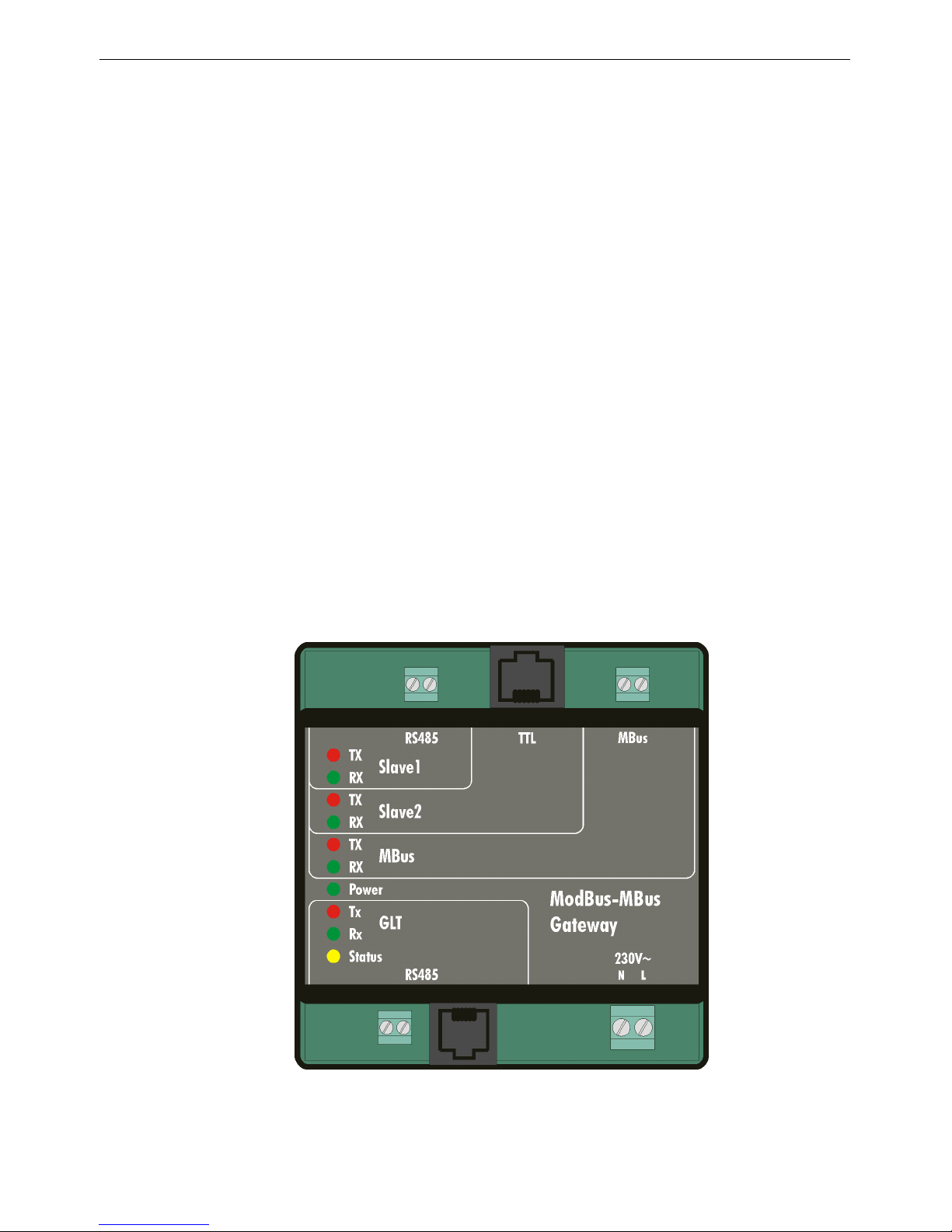
Electrial connecting
The ModBus-MBus-Gateway is to be connected to RJ45 or RJ12 patch cables and terminals. All connectivity options are
described on the front panel.
The connected lines should be layed separately from mains voltage wires.
The supplied RJ45 patch cables shall not be adjusted in length.
EB_11997_ModBus-MBus-Gateway_EN001 3
Slave devices M-Bus devices
Mains
230 V AC
Control system - BMS
2 wire RS485
Page 4

Installation and operating manual KT-Elektronik
Control system communication
Baud rate
The baud rate of the interface to the control system (BMS) is automatically detected and adjusted by the ModBus-MBusGateway. It will support 9600 and 19200 baud.
Addressing
Das Modul ist immer unter der globalen Stationsadresse 254 (FE-hex) im 8-Bit-Stationsadressmodus ansprechbar. Im
16-Bit-Stationsadressmodus gilt die Stationsadresse 65534 (FFFE-hex).
The module is always accessible via the global station address 254 (FE hex) in the 8-bit addressing mode. The station
address 65534 (FFFE hex) applies to 16-bit addressing mode.
Addressing at delivery
When delivered, a class derived from the serial number 8-bit address is set. The station address is the low two digits of the
serial number. A special case of this rule is any serial number with significant digits "00" in this case, the station address to
"100" set.
Addressing by slave device TROVIS 5573, SOL3-1, SOL3-7 and WPR3
The ModBus-MBus-Gateway automatically takes the address from the slave device. In the worst case, the acquisition of the
station address of the slave device takes a few minutes to complete because all station addresses in the supported
addressing modes and all supported baud rates are successively tested for recognition of a slave device.
Address change in stand-alone operation
Through two holding registers may be adjusted an 8-bit station address or a 16-bit address of the ModBus-MBus-Gateway.
The last address written determines the addressing mode of the device.
Connection to the control system BMS
For connection to an RS485 two-wire network to a building management system BMS the ModBus-MBus-Gateway provides
a potential free RS-485 interface with auto phase switching. The RS485 two-wire network can be connected to a two-pole
screw terminal or to an RJ12 jack using RJ12 patch cord. Compliance with a specific polarity is not required.
Connection to the slave device
For connectivity to a slave device the ModBus-MBus-Gateway provides an RS-485 interface through a two-pole screw
terminal and a TTL RS-232 port via an RJ45 socket.
It is just intended to connect to one slave device. The communication parameters of slave device by the MBus ModBus
gateway automatically calculated and applied.
A recognized slave device is indicated by the Status LED.
The station address is automatically transferred from the slave device, the station address set in the ModBus-MBus-Gateway
is ignored.
Holding registers and coils of ModBus-MBus-Gateway and supported slave devices are located in different areas.
Connection to MBus
For connectivity to Mbus devices provides the ModBus-MBus-Gateway an interface to a two-pole screw terminal.
The MBus ModBus gateway is intended for the connection of up to 6 MBus loads.
4 EB_11997_ModBus-MBus-Gateway_EN001
Page 5

KT-Elektronik ModBus-MBus-Gateway
Display and operation
The device has no controls. The device settings are exclusively via a Modbus connection changed. In stand-alone operation,
in which no slave device is connected, the setting of the ModBus-MBus-Gateway has to make by control system BMS. If
one slave device is connected, the setting of the MBus meter configuration can be adjust by using the operation of slave
device.
To indicate operating state and function are 10 luminous dots (LEDs) are located on the front panel of the ModBus-MBusGateway.
LED status
An LED lights up when the value specified for this LED is active.
Send to Slave (RS485)
Receive from Slave (RS485)
Send to Slave (RS232/TTL)
Receive from Slave (RS232/TTL)
Send to Mbus
Receive from Mbus
Operation, Mode
Send to BMS (RS485)
Receive from BMS (RS485)
Status (On → Slave recognized )
There is a special feature of the LED 'Power' in the mode 'update'. In this mode, the LED lights with short breaks.
EB_11997_ModBus-MBus-Gateway_EN001 5
Page 6

Installation and operating manual KT-Elektronik
Updating the firmware
To perform an firmware upgrade of the ModBus-MBus-Gateway, use the software BootManager. At the time of the firmware
update it is not allowed to connect one slave device.
A firmware upgrade for a connected slave device can be carried out using the software BootManager. In this case the
ModBus-MBus-Gateway provides a transparent connection between BootManager and slave device.
Configuration using 5012Config
For the configuration of the connected MBus meters, the software 5012Config is available. This tool can be adjust meter
address, meter type, meter read interval and meter schedule. Also may consider MBus meter data read by the ModBusMBus-Gateway.
The software 5012Config is available in German language only.
6 EB_11997_ModBus-MBus-Gateway_EN001
Page 7

KT-Elektronik ModBus-MBus-Gateway
Technical specification
Interfaces 1 x control system interface BMS: RS485 2 wire network, potential free,
9600 baud, 19200 baud (automatically)
8 bit, no parity, 1 stop bit
MODBUS RTU
1 x slave interface: RS-485 2 wire network, slave device potential,
9600 baud, 19200 baud (automatically)
8 bit, no parity, 1 stop bit
MODBUS RTU
only for TROVIS 5573, SOL3-1, SOL3-7 and WPR3
1 x MBus interface (meter network), 2 wire network, potential free
meter network (M-Bus) according to EN 1434-3 or adapted
Operating voltage 85 to 250 V, 48 to 62 Hz, max. 1,8 W
Ambient temperature 0 to 40 °C (operation),
–10 °C to 60 °C (storage and transport)
Type of protection IP 20 according to IEC 529
Protection class II according to VDE 0106
Pollution degree 2 according to VDE 0110
Overvoltage category II according to VDE 0110
Humidity class F according to VDE 40040
Housing material PA6 (base), PA66 (housing), PC (plate)
Standard EN 60730, EN 60950
Noise immunity according to EN 61000-6-1
Noise emission according to EN 61000-6-3
Mounting DIN rail according to EN 50022
Terminals RJ45, RJ12, 3x plug-in terminals
Housing L x W x H (mm) 94 x 96 x 60
Assembly Manual, RJ45 patch cable and RJ12 patch cable
Weight approx. 0,15 kg
EB_11997_ModBus-MBus-Gateway_EN001 7
Page 8

KT-Elektronik GmbH
Berlinickestrasse 11
12165 Berlin - Germany
Telephone: (030) 79 08 05-0
Telefax: (030) 79 08 05-20
E-mail: info@kt-elektronik.de
Internet: http://www.kt-elektronik.de
EB_11997_ModBus-
MBus-
Gateway_EN001
11/2012
 Loading...