

K-TEK MT5100 Operation Manual

MT5100
Guided Wave Radar Level and Interface Transmitter
Installation & Operation Manual
MT5100
Guided Wave Radar Level and Interface Transmitter
For the latest version of this manual, visit ktekcorp.com.
MT5100-0200-1 Rev b (2-2013) DCN0365

MT5100
Guided Wave Radar Level and Interface Transmitter
TABLE OF CONTENTS
1. Introduction ............................................................................................................................................................ 4
2. Overview ................................................................................................................................................................ 5
2.1 Storage and Handling Information ................................................................................................................. 5
2.2 Ambient Temperature .................................................................................................................................... 5
2.3 Description and Principle of Operation .......................................................................................................... 6
2.4 Total Level and Interface Level Measurement .............................................................................................. 7
3. Installation .............................................................................................................................................................. 8
3.1 Special Requirements ................................................................................................................................... 8
3.2 Mechanical Installation .................................................................................................................................. 9
3.2.1 Shortening of the Probe ..................................................................................................................... 9
3.2.2 Plastic Tanks, Fiberglass Tanks, and Open Air Installations ............................................................. 9
3.2.3 Single Probes in Stilling Wells ............................................................................................................ 10
3.2.4 Single Probes in External Chambers ................................................................................................. 12
3.2.5 Dual Rod/Cable Probes ...................................................................................................................... 13
3.2.6 Coaxial Probes ................................................................................................................................... 13
3.2.7 Unmeasurable Zones ......................................................................................................................... 14
3.3 Shortening of Probes ..................................................................................................................................... 15
3.4 Electrical Installation ...................................................................................................................................... 15
4. Commissioning ....................................................................................................................................................... 16
4.1 Display Operation .......................................................................................................................................... 16
4.1.1 Jumper Settings ................................................................................................................................. 17
4.1.2 Push Buttons ...................................................................................................................................... 17
4.2 MT5100 Menu Flow Chart ............................................................................................................................. 18
4.3 Basic Setup ................................................................................................................................................... 19
4.3.1 Units ................................................................................................................................................... 19
4.3.2 Probe Type ......................................................................................................................................... 19
4.3.3 Probe Length ...................................................................................................................................... 20
4.3.4 Offsets ................................................................................................................................................ 21
4.3.5 Upper Dielectric .......................................................................................
4.3.6 Actual Interface .................................................................................................................................. 22
4.3.7 Lower Dielectric (Optional) ................................................................................................................. 22
4.3.8 Language............................................................................................................................................ 23
4.4 Quick Calibration ........................................................................................................................................... 23
4.5 mA Output Setup ........................................................................................................................................... 24
4.5.1 Output ................................................................................................................................................. 24
4.5.2 LRV 4mA ............................................................................................................................................ 24
4.5.3 URV 20mA.......................................................................................................................................... 25
4.5.4 Dampening ......................................................................................................................................... 25
4.5.5 Alarm Delay ........................................................................................................................................ 26
4.5.6 DAC Trim ............................................................................................................................................ 26
4.5.7 LOOP Test.......................................................................................................................................... 26
4.5.8 HART Address ................................................................................................................................... 27
4.6 Extended Setup ............................................................................................................................................. 27
4.6.1 Waveform Display .............................................................................................................................. 28
4.6.2 Functions ............................................................................................................................................ 30
4.6.3 Temperature ....................................................................................................................................... 31
4.6.4 Flooded Chamber ............................................................................................................................... 31
4.6.5 Flooded Total ..................................................................................................................................... 31
4.6.6 Linearization Menu ............................................................................................................................. 32
4.6.6.1 Linearization for Measurement ............................................................................................. 33
4.6.6.2 Linearization for Volume ...................................................................................................... 34
4.6.6.3 Linearization for Flow ........................................................................................................... 35
4.6.6.4 User Functions ..................................................................................................................... 36
4.7 Secondary Output - RI100 Option ................................................................................................................. 36
MT5100-0200-1 Rev b (2-2013) DCN0365 2
........................................... 22

MT5100
Guided Wave Radar Level and Interface Transmitter
5. Troubleshooting ..................................................................................................................................................... 37
5.1 Valid Current Loop Outputs ........................................................................................................................... 37
5.2 Symptoms and Solutions ............................................................................................................................... 38
5.3 Electronics Module Replacement .................................................................................................................. 38
6. Installation Drawings for Intrinsic Safety & Standard Wiring ................................................................................. 39
7. Loop Powered TX Hookup / RI Dual Compartment Housing ................................................................................ 42
8. CE Certificate of Compliance ................................................................................................................................ 43
9. Customer Support ................................................................................................................................................. 44
9.1 RMA Form ...................................................................................................................................................... 45
10. Warranty Statement .............................................................................................................................................. 46
MT5100-0200-1 Rev b (2-2013) DCN0365 3

MT5100
Guided Wave Radar Level and Interface Transmitter
1. Introduction
Thank you for using the K-TEK MT5100 Guided Wave Radar Liquid Level and Interface Transmitter. The MT5000
series is a second generation of products which have been designed for simplicity of setup while offering extensive
configuration capabilities. You are invited and urged to review this instruction manual in its entirety prior to use of
the transmitter. This will eliminate most installation problems due to improper configuration.
We, the K-TEK Family, sincerely hope you receive many years of reliable use from the MT5100 transmitter and
welcome your feedback to consistently improve our all of our products. It is our desire to provide you, the user, with
the most reliable, customer friendly device to suit your application needs.
When it comes to measuring the level of liquids, guided wave radar technology now offers more level-detection
capabilities than ever before. For an ever-widening range of previously hard-to-measure products such as molten
sulfur, liquid ammonia and petrochemicals, guided wave radar transmitters provide accurate level measurements
even under harsh chemical environments, wide variations in operating temperatures and pressures, and low
dielectric constants. Great strides have also been taken in making these units easier to configure to a variety of
process applications coupled with the simplicity of integrating these devices with most digital communication
protocols. These improvements come as a welcome relief to process engineers that seek solutions to measuring the
contents of tanks, silos, hoppers, bins, mixing basins, and vessels in an expanded range of level applications across
several different industries.
Because a guided wave radar transmitter has no moving parts, it has established itself as a level measurement
technology that has distanced itself from traditional mechanical means, which don't hold up as well in dirty service.
Guided wave radar achieves its non-mechanical level detection capability by measuring the time of flight of the
transmitted signal.
Known more accurately as Time Domain Reflectometry (TDR), the process involves:
1. Sending microwave energy down into a vessel guided by an antenna.
2. When the pulse of radar energy reaches the product (indicated by a change in impedance), part of the
pulse is reflected back toward the transmitter.
3. A receiver measures the exact duration of time between the transmitted and reflected signal—the "time
of flight."
4. The device analyzes this time and ultimately displays the level of the product as a distance in inches,
feet, meters, or other engineering units.
The MT5100 transmitter was developed with ease of operation in mind. We made use of a graphic display to
provide a more user friendly aspect to the transmitter configuration. The graphic display allowed us to incorporate
multiple language options in the setup menu such as English, Spanish and Chinese. In the incorporation of the
graphic display, the electronics were converted to a digital format. This provided a greater signal recognition
capability and an ability to include an “onboard oscilloscope” as an aid in troubleshooting tough applications.
The emphasis on simplicity extended itself beyond the use of multiple languages. The Basic Setup menu has been
designed with a series of multiple choice questions which, when answered correctly, will configure the transmitter to
the installation. The mA Output Setup menu has been expanded to include Loop Test and HART
capabilities.
Coupled with the development of the MT5100 series was the development of the KCOM™ software. KCOM™ is a
diagnostic tool which allows the MT5100 to be remotely configured using a computer and HART
Beyond the Basic Setup parameters, the software will allow the user to view the return signal of the MT5100 on the
computer screen. As a trouble shooting tool, a screen shot of the waveform may be taken and sent to the factory for
analysis. The KCOM™ software is free and may be downloaded from our website at www.ktekcorp.com
For more information on the MT5100 series including liquid/liquid interface and bulk solids measurement visit our
website at www.ktekcorp.com
.
®
interface modem.
®
Address
.
MT5100-0200-1 Rev b (2-2013) DCN0365 4

MT5100
Guided Wave Radar Level and Interface Transmitter
2. Overview
2.1 Storage and Handling Information
If possible, storage prior to installation should be indoors at ambient temperature, not to exceed the following:
Temperature range: -40 to 150 degrees F.
Humidity: 0 to 100% R.H. non-condensing.
To avoid probe damage:
Do not transport or support the weight of the MT5100 by means of the probe.
Installation of rigid probes and flange mounted transmitters may require the use of lifting equipment.
Avoid sharp bending of cable probes which can result in poor instrument operation.
The lids on the MT5100 housing are sealed with o-rings. To avoid damage to the electronics, both lids should be closed
tightly before and after installation.
2.2 Ambient Temperature
The MT5100 electronics temperature may not exceed 170°F / 77°C. For higher ambient temperatures due to radiant
process heat, a high temperature extension option is required. The coupler process temperature shall not exceed
the temperature stated in the datasheet specifications for the given coupler.
MT5100-0200-1 Rev b (2-2013) DCN0365 5
MT5100
Guided Wave Radar Level and Interface Transmitter
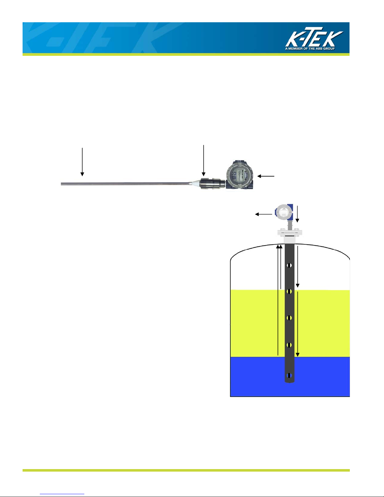
2.3 Description & Principle of Operation
The MT5100 is a 4-20mA loop powered Smart Level Transmitter, which is microprocessor based and is available
with HART
products being measured. In order to obtain optimum performance, it is important to understand the basic principle
of operation. The electronics housing is fitted with a special adapter “Coupler” serving as a process connection and
seal, which holds a solid rod or a cable. The rod or cable “Probe” hangs into the vessel and acts as a wave-guide,
i.e. the probe guides the microwave energy to the product surface, instead of being dispersed in a cone, as it would
be if there was no probe.
A measurement cycle consists of the following:
1. A very short “pulse” of microwave energy is applied at the
2. The pulse travels along the length of the probe and when it
3. When the reflected energy from the level reaches the coupler, it
4. The energy not reflected by the level passes through the upper
5. When the reflected energy from the interface level reaches the
6. Since the microwave energy travels at the speed of light, one
7. The measurement cycles are made 2 times per second and are
®
communication. It uses very low power microwave energy to determine the level or interface of the
PROBE
coupler, to the Probe.
encounters a discontinuity that is a dielectric constant change, at
the level surface, some of the energy is reflected and travels
back towards the coupler.
is sensed by the electronics. By measuring the time elapsed
between the initial pulse and the reflected one, the electronics
can calculate the level.
fluid and is reflected at the interface level.
coupler, it is sensed by the electronics. The electronics then
calculate the level of the interface using the known dielectric
constant and level of the upper fluid.
complete measurement cycle is made up of several thousands
of Pulses. The electronics uses Time Domain Reflectometry
(TDR), a sampling technique to reconstruct a waveform for both
levels duplicating the actual real time signal, but at a much lower
speed, so that it can be processed by the microprocessor. This
process can be compared to using the stroboscope effect as
when observing a piece of machinery turning at high speed with
a strobe light.
processed by special filtering techniques, before generating a
current output proportional to the level or interface of the
products.
COUPLER
HOUSING
7
6
3
5
1
2
4
MT5100-0200-1 Rev b (2-2013) DCN0365 6
MT5100
Guided Wave Radar Level and Interface Transmitter
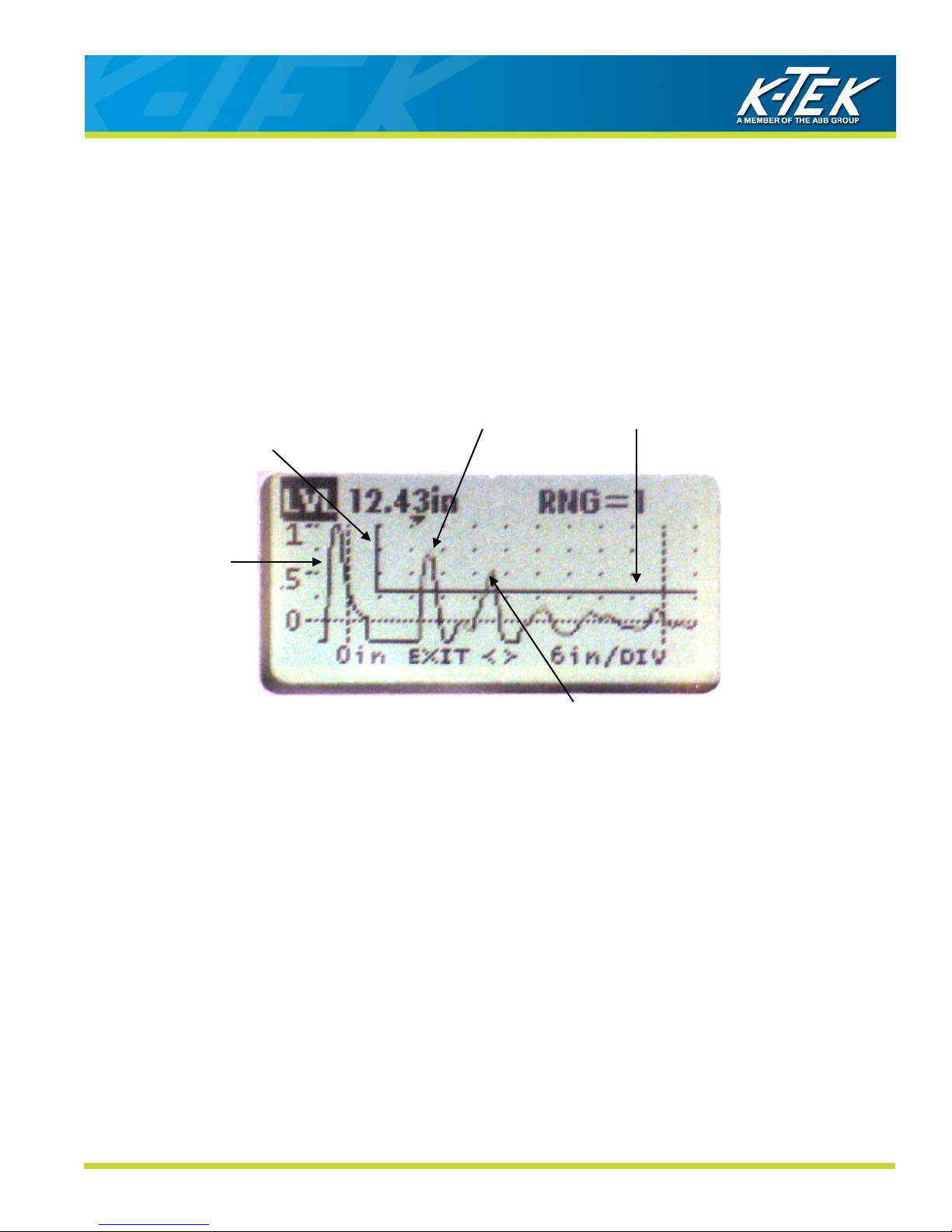
A simplified signal trace as seen on the graphic display (Figure 2.1) can be divided into three identifiable sections:
- Coupler Reflection.
- Level Reflection
- Interface Reflection
The measurement principle using TDR is based on the fact that a dielectric constant discontinuity or geometric
change will yield a positive pulse having certain amplitude above the baseline. The greater the dielectric constant
difference, the greater the positive amplitude of the return signal. This means that a signal will show up on the
baseline if there is a substantial change from a nozzle diameter to an open tank, for example, as signal plot at the
process connection. This fact will be taken into account in the configuration of the MT5100 (Consult Basic Setup
(Section 4.3 on Commissioning).
Figure 2.1
Blanking
Level Reflection
Coupler Reflection
Interface
Reflection
Level Threshold
Interface
Threshold
Note: Operation is subject to the following two conditions:
1. This device may not cause harmful interference.
2. This device must accept any interference received, including interference that may cause undesired operation.
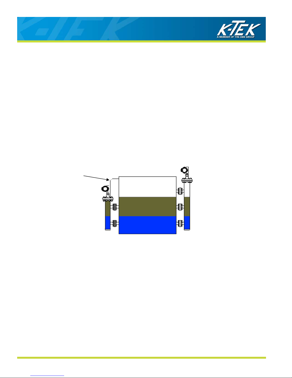
2.4 Total Level and Interface Measurement
1. If the application utilizes the “non-flooded chamber” menu selection, both the total level and the interface level
can be obtained from a single process connection when the MT5100 is utilized with a RI100 Repeat Indicator.
2. The MT5100 provides a 4-20 mA output representing the interface level while the RI100 provides a 4-20 mA
signal representing the overall level.
3. While this type of application works best with the MT5100 mounted directly on the vessel, an external chamber
with a minimum of three process connections can also be utilized as long as ONLY one interface level (liquidliquid or liquid-vapor) occurs between any two (adjacent) process connections.
4. See drawing ELE1004 in this manual’s appendix for the RI100 wiring diagram.
5. See the RI100 Data Sheet and consult K-TEK for additional information.
MT5100-0200-1 Rev b (2-2013) DCN0365 7
MT5100
Guided Wave Radar Level and Interface Transmitter
3. Installation
3.1 Special Requirements
In order to properly detect the level of interface between two liquids using the MT5100, the following rules must be
adhered to:
1. One of the following probe and mounting configurations must be used:
a. Single rigid rod or flexible cable mounted in a stilling well, external chamber, or existing
displacer.*
Minimum inside pipe diameter - 1.939 in. (2 in. sch. 80)
Maximum inside pipe diameter - 4.26 in. (4 in sch. 10)
For other pipe diameters, consult factory.
Maximum probe length:
Single rod - 20 ft.
Flexible cable - 30 ft
b. Dual rigid rod or flexible cable
Maximum probe length
Dual rigid rod - 20 ft
Dual flexible cable - 65 ft
c. Coaxial probe mounted into tank, external chamber, or displacer
Maximum probe length - 22 ft
Both fluids must be clean
* This is the preferred mounting configuration to reduce the chance of fouling.
2. Emulsion layers will affect the detection of an interface level. An emulsion layer may negate an interface level
indication completely. The MT5100 will read an interface level in the presence of a 2 inch emulsion. The MT5100
is equipped with a weak interface signal detector (patent pending). This visual indication will let the user know
when an emulsion layer may be present.
3. The minimum upper fluid thickness must be 4 inches when emulsion is present, and 0 inches with a clean
interface.
4. The upper fluid dielectric constant must be greater than 1. 6 and less than 5.
5. The interface level indication is a calculated value based partially upon the dielectric of the upper fluid. The
upper fluid dielectric must remain constant for consistency / accuracy in the interface level indication.
6. The lower fluid dielectric constant must not be less than 15.
7. If the application is a flooded condition (sensor completely submerged in process), it must remain completely
flooded.
8. In a non-flooded condition, the upper fluid must not be allowed to enter the upper unmeasureable zone. The
upper unmeasureable zone is typically located within the mounting nozzle of the vessel.
If the required interface application does not fall within the above mentioned parameters, please consult the factory
for an alternate technology, such as a Magnetostrictive, Magnetic Level Gauge or RF Capacitance.
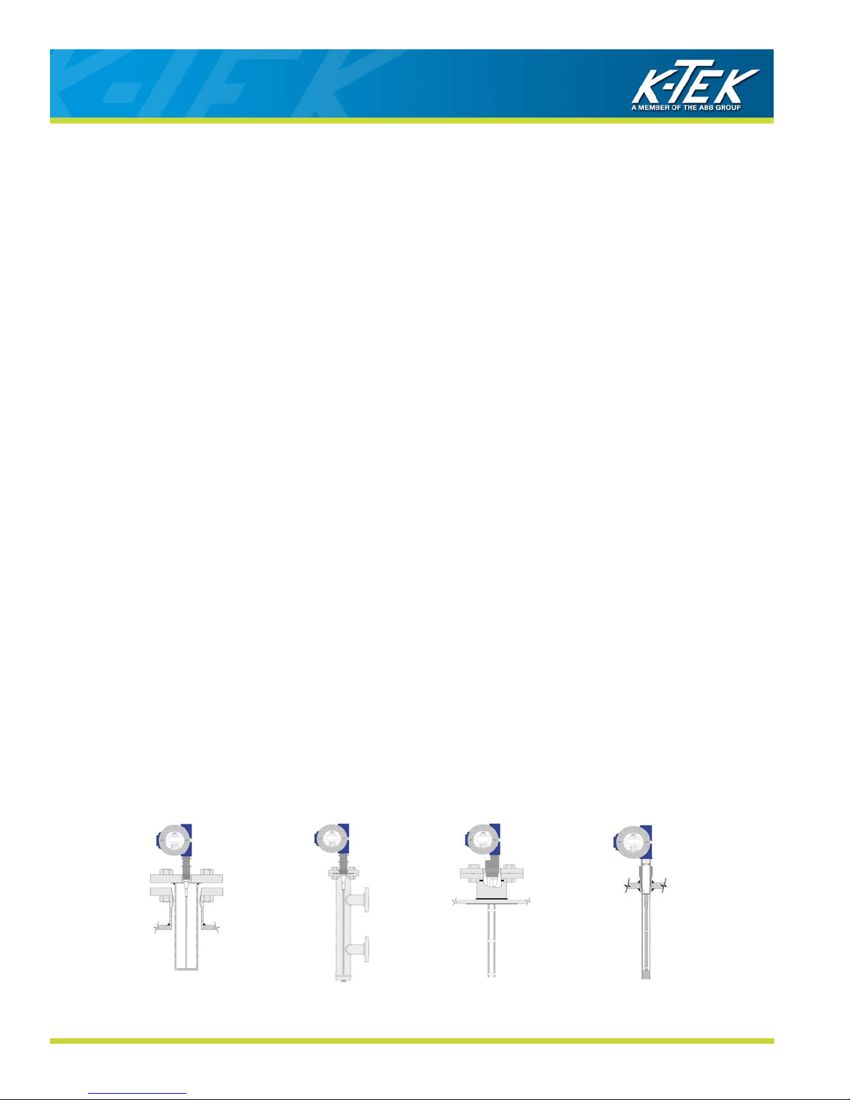
Stilling Well & Tri-Band
Preferred Configuration
MT5100-0200-1 Rev b (2-2013) DCN0365 8
Preferred Configuration
Flooded or Non-Flooded
External Chamber
Dual Rigid Rod Coaxial

MT5100
Guided Wave Radar Level and Interface Transmitter
3.2 Mechanical Installation
3.2.1 All Installations
1. Do not mount the MT5100 in the product fill stream.
2. To obtain the best return signal from the product level mount the MT5100 coupler directly into the top of the vessel.
3. Do not mount MT5100 single probes using bushings. (Figure 3.1)
4. Ideally, probes should be mounted in the center of the vessel to provide the maximum measuring range.
5. Avoid internal obstructions such as tubing, ladders or agitators.
6. An MT5100 installed in a nozzle whose height is greater than its width will have an increased non-linear zone at
the top of the probe.
7. Cable probes with weights should be allowed to hang under the tension of the weight within the vessel. Shortening of the probe may be required.
8. To avoid excessive movement of the MT5100 probe in an agitated process, or where installation close to the
vessel wall is required, secure the bottom end of the probe to the vessel. Probes installed from top of the vessel
may require the use of a stilling well.
9. Probes installed in side vessel connections require additional probe support within the nozzle connection.
10. Threaded connections should be installed with thread sealant approved for use by the consumer. Flanged
connections should be made using materials (bolts, studs, nuts, and gaskets) and procedures (torque specifications) approved by the consumer.
Figure 3.1
3.2.2 Plastic Tanks, Fiberglass Tanks, and Open Air Installations
Dual Probe transmitters should not be used to measure interface levels in non-metallic vessels or open air installations. Single probes in stilling wells or coaxial probes should be used to prevent interruptions in transmitter operation.
MT5100-0200-1 Rev b (2-2013) DCN0365 9
CORRECT
INCORRECT

MT5100
Guided Wave Radar Level and Interface Transmitter
3.2.3 Single Probes in Stilling Wells
An MT5100 with a single probe directly inserted in the vessel can be used to measure interface level if a metal stilling well is also utilized. This stilling well may already exist, as part of the tank structure, or may be purchased with
the MT5100.
1. The inside diameter of the chamber must not be less than 1.939 inches, the equivalent of 2” schedule 80
pipe (Consult factory for smaller sizes).
2. The inside diameter of the chamber must not be greater than 4.26 inches, the equivalent of 4” schedule 10
pipe (Consult factory for larger sizes).
3. If a rigid type probe is used, a centering disc is required to center the probe in the chamber and provide an
end of probe target.
4. If a flexible type probe is used, a centering weight is required to straighten the cable, center the cable, and
act as an end of probe target.
5. The upper fluid must not be allowed to enter the unmeasureable zone. This can be accomplished by
keeping the dimension between the top edge of the highest stilling well hole and the face of the coupler
greater than the unmeasureable zone (Section 3.2.7).
The hole pattern of the stilling well will be critical in determining the accuracy and reliability of the interface
measurement. One of the following hole patterns must be present for an existing stilling well to be used with the
MT5100 interface option.
For some applications a simple pattern of three holes in the stilling well will be suitable. The top hole will allow the
vapor to enter the stilling well. The center and bottom holes will allow the fluids to enter and equalize, if they are
placed properly. This will work if the upper fluid level continuously covers the center hole. If the upper fluid level
were to rise or fall from the center hole, the upper fluid would be cut off from the probe and inaccurate measurement
would result.
MT5100-0200-1 Rev b (2-2013) DCN0365 10
OIL
WATER
MT5100
Guided Wave Radar Level and Interface Transmitter
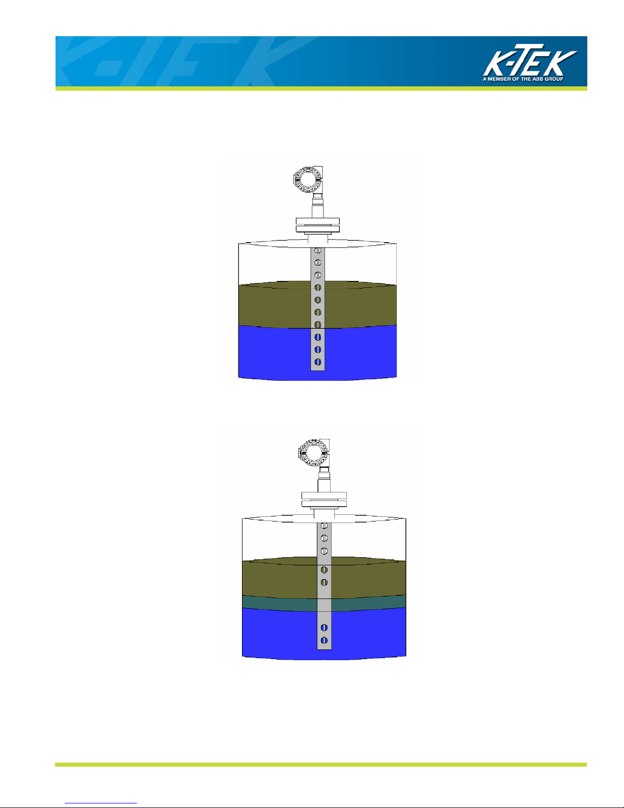
An ideal installation involves the use of multiple holes along the length of the stilling well. This will allow both
products to flow freely over the entire length of the probe. A typical stilling well purchased from K-TEK will have 1”
holes placed at 1.5” centers down the length of the stilling well with the top edge of the highest hole at 6 inches form
the face of the coupler.
OIL
WATER
The presence of an emulsion layer in the interface process can create problems with the interface measurement. If
the emulsion layer is known to exist in a specific area in the length of the probe, the holes in the stilling well can be
drilled to minimize the effects of the emulsion layer.
OIL
EMULSION
WATER
If the nozzle dimension on the top of the vessel is not greater than 4”, an additional stilling well or coaxial type probe
must be used.
In all cases, the upper most hole in the side of the stilling well should be kept outside of the unmeasureable
zone (Section 3.2.7). Stilling wells purchased from K-TEK will have the above factors taken into account during
manufacture. If you cannot accept the terms listed above, consult the factory for an alternate solution.
MT5100-0200-1 Rev b (2-2013) DCN0365 11
MT5100
Guided Wave Radar Level and Interface Transmitter
3.2.4 Single Probes in External Chambers
The single probe MT5100 may be installed in an External Chamber in order to measure interface level. The External
Chamber may already exist or be purchased from K-TEK. There are some guidelines which must be followed in
order to maintain proper operation of the transmitter.
1. The inside diameter of the chamber must not be less than 1.939 inches, the equivalent of 2” schedule 80 pipe
(Consult factory for smaller sizes).
2. The inside diameter of the chamber must not be greater than 4.26 inches, the equivalent of 4” schedule 10 pipe
(Consult factory for larger sizes).
3. If a rigid type probe is used, a centering disc is required to center the probe in the chamber and provide an end
of probe target.
4. If a flexible type probe is used, a centering weight is required to straighten the cable, center the cable, and act as
an end of probe target.
5. Two process connection configurations are typical for external chambers used to measure interface level:
a. The first configuration (Figure A) has two process connections and is commonly used for flooded cham-
ber interface measurement. In this configuration, a vent line back to the process should be used to keep the
chamber flooded.
Figure B Figure A
Vent
Line
VAPOR
OIL
WATER
b. The second configuration (Figure B) has three process connections. The top connection allows the va-
por space to equalize within the chamber and can be used to measure both total and interface level.
This chamber design is less likely to become flooded due to the distance between the top process
connection and the face of the coupler.
6. A MT5100 Interface option, set for a flooded condition (Figure A), must always remain flooded. Should the
chamber become non-flooded during operation, the transmitter will return false indications which could result in
process upsets and hazardous conditions.
7. If the configuration is non-flooded (Figure B), the upper fluid must not be allowed to enter the unmeasureable
zone. This can be accomplished by keeping the dimension between the top process connection and the access
flange greater than the unmeasureable zone (Section 3.2.7).
If the External Chamber for the MT5100 is being supplied by K-TEK Corporation, all of the above factors will be
taken into account during the manufacture.
Some interface applications may contain emulsion layers that interfere with the operation of guided wave radar
transmitters. Installing the MT5100 in an external chamber will allow the process to settle within the chamber and
reduce the affects of the emulsion on the interface level signal.
MT5100-0200-1 Rev b (2-2013) DCN0365 12

MT5100
Guided Wave Radar Level and Interface Transmitter
3.2.5 Dual Rod/Cable Probes
Dual Probe options do not require the use of an additional stilling well for operation. If the process environment
requires the use of a stilling well to prevent movement, a single probe design with a metal stilling well will be
sufficient. If the transmitter is to be mounted in an external chamber or displacer, single probes or coaxial probes are
the preferred probe types.
When installing a dual probe into a vessel for level detection, there are several things to consider:
1. The probe should not be mounted in the path of the product stream entering the vessel.
2. The probe should not be mounted within 6 inches of any construction within the vessel including ladders,
weirs or internal piping.
3. Tanks constructed of concrete require probe mountings to be:
a. 1 ft. / 0.3 m from wall with up to 20 ft. / 6.1 m measuring length
b. 2 ft. / 0.61 m from wall over 20 ft. / 6.1 m measuring length
4. The face of the MT5100 mounting/launch plate on dual probe transmitters mounted in concrete vessels
should be even with the inner surface of the concrete roof.
5. Dual probe designs incorporate spacers to separate probes at an equal distance. These spacers are points
for potential bridging. If the fluids contain floating particles, paraffin or other matter, bridging between the
probes may result. Scheduled maintenance will be required to flush probes of potential buildup.
6. Dual probes installed with nozzle diameters smaller than nozzle heights may require the use of an extended
BLK parameter. Refer to Section 4.5 to adjust this parameter. Extending the BLK may result in a loss of
measurable range.
7. If the MT5100 is set up for a non-flooded condition, the upper product should not be allowed to enter the
upper unmeasureable zone Refer to Section 3.2.7.
If the MT5100 you have received has a dual probe configuration, and you cannot accept the terms listed above, contact the factory for an alternate solution.
3.2.6 Coaxial Probes
Coaxial type probes will provide the best return signals from interface levels but they are not the best probes for
most interface applications. Here are some things to be cautious of when using a coaxial type probe for level
measurement:
1. Coaxial type probes are rigid and designed as a one piece unit. In their construction, a rigid rod is mounted
inside a small tube which acts as an included stilling well. The internal rod is held in the center of the outer
tube using spacers. Care must be taken not to flex or stress the outer tube when installing a coaxial style
probe, particularly probes over 10 ft. This may cause damage to the spacers and lead to improper operation.
2. Coaxial probes are recommended for use in clean fluids only. This will apply to both the upper and lower
fluids being measured. If the fluids contain floating particles, paraffin or other matter, bridging or clogging
within the tube may result. Scheduled maintenance will be required to flush probes of potential build-up.
Single probe configurations are the preferred method for applications with potential build-up.
(Section 3.1)
3. It is acceptable to mount coaxial style probes within external chambers or displacers. While it is possible to
measure low dielectric upper fluids such as propane and butane using a single probe in a 2 inch chamber,
larger chamber sizes may require the use of coaxial probes (Section 3.5).
If the MT5100 you have received has a coaxial style probe, and you cannot accept the terms listed above, contact
the factory for an alternate solution.
MT5100-0200-1 Rev b (2-2013) DCN0365 13
MT5100
Guided Wave Radar Level and Interface Transmitter
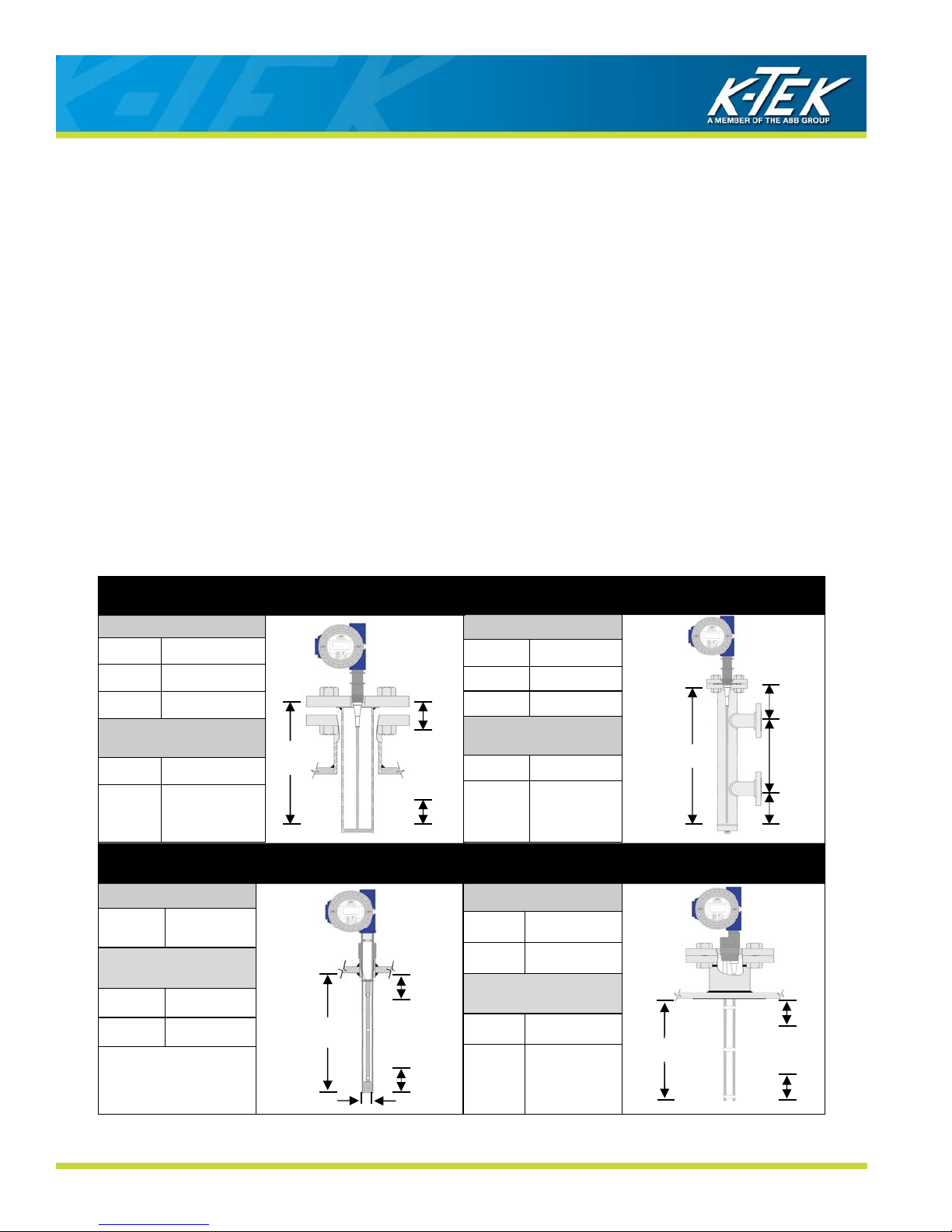
3.2.7 Unmeasurable Zones
Each mounting configuration will be subject to certain Unmeasurable Zones at the top and bottom of the probe.
These unmeasureable zones are characterized as having non-linear readings and in some cases lack of indication.
Careful attention must be paid to the type of probe being used and the mounting configuration used for proper operation of the MT5100.
Unmeasureable zones at the bottom ends of probes are typically small and should not affect transmitter operation
under normal conditions.
Unmeasureable zones at the top of the probes range in size from 0 inches to 4 inches depending upon the installation and probe type. In this area, the indicated level from the product can become non-linear and eventually disappear. When using the MT5100 for interface measurement in a non-flooded configuration, if the upper fluid enters the
top unmeasureable zone, the transmitter will consider the interface reading to be both the total and interface measurement. In a flooded configuration, the unmeasureable zones will only cause errors in the interface measurement.
The upper unmeasureable zone will typically be situated within a nozzle if the MT5100 is mounted directly into a
process vessel. Single probe MT5100s mounted in existing displacers may be subject to having the unmeasureable
zone within the measuring range. In these cases, a coaxial type probe or a single probe with an included stilling well
may be required. External chambers and stilling wells manufactured by K-TEK will be designed to keep the unmeasureable zone outside of the required measuring length of the transmitter.
Dual probe MT5100s are subject to the greatest unmeasureable range and should be considered as a last resort for
measuring interface levels.
P11, P12 2 < IL < 30 FT.
UNMEASURABLE ZONES
INSERTION LENGTH (IL)
P51, P71 2 < IL < 22 FT
SINGLE PROBE IN STILLING WELL
INSERTION LENGTH (IL)
P01 2 < IL < 10 FT.
P02 2 < IL < 20 FT.
L1 4 IN.
L2 1 IN. (+ weight
height for P11
and P12)
IL
COAX (CLEAN FLUIDS ONLY)
UNMEASUREABLE
ZONES
L1 4 IN.*
L2 1 IN.
* 0” Available Upon
Request
IL
7/8”
L1
L2
INSERTION LENGTH (IL)
P11, P12 2 < IL < 30 FT.
L1
L2
INSERTION LENGTH (IL)
P31, P32 2 < IL < 65 FT.
SINGLE PROBE IN EC CHAMBER
P01 2 < IL < 10 FT.
P02 2 < IL < 20 FT.
UNMEASURABLE
ZONES
L1 4 IN.
1 IN. (+ weight
L2
height for P11
and P12)
DUAL PROBE
P22 2 < IL < 30 FT.
UNMEASURABLE
ZONES
L1 4 IN.
IL
L2
2 IN.
(+ weight,
height for P31
and P32)
IL
L1
ML
L2
L1
L2
MT5100-0200-1 Rev b (2-2013) DCN0365 14

MT5100
Guided Wave Radar Level and Interface Transmitter
3.3 Shortening of Probe
The MT5100 single rod and cable probe can be cut to length prior to installation. If shortening of the probe is necessary, cut the rod or cable to the desired length using a hacksaw.
Shortening of coaxial probes or Tri-Band probes in the field is not recommended.
The centering disc or weight at the end of the probe must be reattached for proper operation.
The Probe Length parameter in the Basic Setup menu will need to be adjusted for the new probe length.
3.4 Electrical Installation
Electrical connection to the MT5100 should approach the transmitter head from below the conduit opening to provide
a drain for moisture. Install conduit to ½” NPT port and run 18 gauge twisted, shielded pair to housing. Refer to
page 40 for typical loop wiring diagram and to page 38-39 for instructions applicable to intrinsic safety installation.
Apply loop power to the transmitter as follows:
Terminal Block + 14 VDC minimum to 36 VDC Maximum
Terminal Block - To control System Input
Ground Screw GROUND
Note: The “+Meter” and “-Meter” terminals are available to hook up a mA meter to monitor loop current, without
breaking the loop.
The housing cover can only be removed when the unit is installed in a non-hazardous area, when
installed with intrinsic safety barrier, or when power is removed from the transmitter.
Ground
Screw
MT5100-0200-1 Rev b (2-2013) DCN0365 15
 Loading...