

K-TEK MS30, MS30EX Operation Manual
MS30/EX Explosion Proof MS30
MS30-0200-1 Rev d (10-2010) DCN0530
Table of Contents
1.0 Description ............................................................................................................................................................ 3
2.0 Application ............................................................................................................................................................ 3
3.0 Operation ............................................................................................................................................................... 3
4.0 Mounting & Installation ........................................................................................................................................ 3
5.0 Maintenance .......................................................................................................................................................... 4
6.0 Appendix ............................................................................................................................................................... 4
6.1 D.C. Applications ........................................................................................................................................... 4
6.2 A.C. Applications ........................................................................................................................................... 4
7.0 Electrical Installation............................................................................................................................................ 5
8.0 Installation and Parts ......................................................................................................................................... .6
9.0 Warranty Statement .............................................................................................................................................. 7
10.0 RMA Form ............................................................................................................................................................ 8
MS30-0200-1 Rev d (10-2010) DCN0530 2

1.0 Description
The K-TEK MS30 is a magnetically actuated single pole, double throw switch. When the MS30 is mounted on a
KM26 Magnetic Level Gauge, LS Series Cage Level switch or an External Chamber that contains a K-TEK magnetic
float, it can sense high or low levels within a vessel. The unique magnetic coupling action eliminates the need for
things as seals, diaphragms, spring or torque tubes because there is no physical contact with the process. Magnetic
coupling also eliminates the necessity of process connections and insures total isolation from the process.
2.0 Application
The MS30 will provide either a normally open or normally closed dry contact which may be used to activate external
devices such as alarms or solenoids. Its main application is to sense the passing of a magnetic float in a KM26, or
similar chamber, attached to a vessel containing a fluid. These trip points can be used for alarms for to activate a
pump motor starter relay.
3.0 Operation
The MS30 consists of a form C reed switch and a bias magnet. The reed switch uses precious metal contacts in an
inert gas atmosphere sealed by glass to metal bond. The bias magnet allows the switch to maintain its last state
(latch) after the activating magnetic field is removed. A magnetic K-TEK float traveling relative to the MS30 causes
the reed switch to change state. After the float has passed, the reed switch will maintain it s state until the float reverses direction and passes the switch in the opposite direction. The action of the switch is break before make. The
hermetically sealed contacts serve to insure a high degree of hazardous area safety, weather resistance and general
reliability of the product.
4.0 Mounting & Installation
The MS30 is mounted using two stainless steel clamps that pass through the mounting slots attached to the switch
housing. The switch can be easily positioned by loosening the clamp and sliding the switch to the correct position on
the chamber. Other switches can be added at any time, without the concern for additional process piping or valves.
Note that two switches can be mounted so that they can trip at the same point or at two points separated by less
than the length of a switch.
MAKE SURE CIRCUIT IS DE-ENERGIZED WHILE INSTALLING THE SWITCH.
The following procedure outlines the steps necessary to install the switch:
1. Mount the switch to the chamber where you want the switch to trip. The switch should be mounted 90° from the
indicator assembly to insure optimum magnetic coupling.
2. Hook the field wires to the pigtail from the MS30 according to the application. See the wiring diagram on the
drawing of Installations and Parts on page 7.
3. The float must be cycled past the switch in both directions to insure that the switch will operate properly when
put into service.
NOTE:
A. All field wiring that is connected to the MS30 switch must comply with the National Electric Code guidelines.
B. Do not use the switch on chambers with operating temperatures above 300°F / 149°C without using insulation
between the switch and the chamber to keep the temperature of the switch from exceeding 300°F/ 149°C. Consult factory.
C. KM26 chambers that are furnished with factory installed insulation blankets, the switch may be mounted via spe-
cial rod mount brackets to a factory installed switch mount rod that is external to the insulation.
D. Any conduit or fittings hooked to either a MS30 or MS30EX magnetically activated switch should be aluminum or
some other non-magnetic material. This is necessary to avoid interference with the operation of the KM26 Magnetic Liquid Level Indicator or other magnetically activated switches.
MS30-0200-1 Rev d (10-2010) DCN0530 3
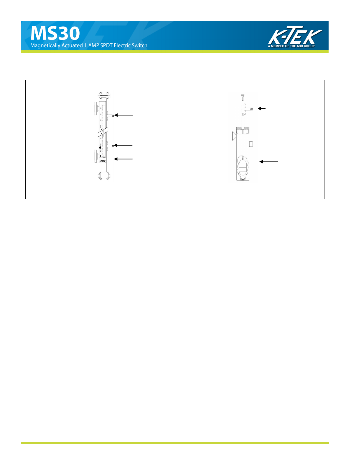
4.0 Mounting & Installation (cont’d)
Example Configurations:
MS30 (HI LEVEL SWITCH)
MS30 (LO LEVEL SWITCH)
KM26 MLG
MS30
LS700
(LS Series)
MS30 Mounted on KM26 Magnetic Level Gauge MS30 Mounted on LS Series
Mechanical Level Switch
MS30-0200-1 Rev d (10-2010) DCN0530 4
 Loading...