

K-TEK AT100, AT100S Operation Manual


TABLE OF CONTENTS
1.0 INTRODUCTION ............................................................................................................................................... 4
2.0 STORAGE INFORMATION .............................................................................................................................. 5
3.0 INSTALLATION AND BASIC WIRING ............................................................................................................. 5
3.1 All Installations ............................................................................................................................... 5
3.1.1 Compression Fittings ............................................................................................................ 5
3.1.2 Floats .................................................................................................................................... 5
3.1.3 Transmitter Housing Height .................................................................................................. 5
3.2 Stilling Probes ................................................................................................................................ 5
3.2.1 Assembly Instructions for F1 Flexible Probes ....................................................................... 6
3.3 Loop Wiring .................................................................................................................................... 6
3.4 Jumper Settings ............................................................................................................................. 6
4.0 TRANSMITTER CALIBRATION AND SETUP ................................................................................................. 7
4.1 Level Output Calibration ................................................................................................................ 7
4.1.1 Calibration Using the Pushbuttons ........................................................................................ 7
4.2 Reversing Action ............................................................................................................................ 7
4.2.1 Reverse Action Calibration Using the Pushbuttons .............................................................. 7
4.3 Damping ......................................................................................................................................... 7
4.4 Calibration Using the LCD Setup Menu ......................................................................................... 9
4.5 Selecting a Primary Variable (PV) ................................................................................................. 9
4.6 Selecting an Engineering Unit for Measurement (EUN) .............................................................. 10
4.7 Level Offsets (L1O and L2O) ....................................................................................................... 10
4.8 DAC Trim ..................................................................................................................................... 10
4.9 Temperature Output ..................................................................................................................... 10
4.9.1 Selecting the Unit of Temperature (EUN TEMP) ................................................................ 10
4.9.2 Temperature Output Calibration .......................................................................................... 11
4.9.3 Temperature Reset (TMP RSET) ........................................................................................ 11
4.9.4 Temperature Master Calibration ......................................................................................... 11
4.10 Volumetric Strapping .................................................................................................................. 12
4.10.1 How the Strapping Table Works ....................................................................................... 12
4.10.2 Setting Up (or resetting) the Strapping Table .................................................................... 12
4.10.3 Selecting the Input Mode (Automatic or Manual) .............................................................. 12
4.10.4 Setting Up Strapping Table Points .................................................................................... 13
4.10.5 Notes on Strapping Table Usage ...................................................................................... 13
4.10.6 Saving/Loading a Strapping Table .................................................................................... 13
4.10.7 Setting Current Output Based on Volume ......................................................................... 13
4.11 Alarm Delay ........................................................................................................................................ 14
4.12 Custom Current Ranging ............................................................................................................ 14
4.12.1 Description and Method of Operation ................................................................................ 14
4.12.2 CCR Set Up ....................................................................................................................... 14
5.0 COMMUNICATION OPTIONS ........................................................................................................................ 15
5.1 Hart Protocol Interface Option ..................................................................................................... 15
5.1.1 Using a 268/275/375 Rosemount Communicator or Equal ................................................. 15
5.2 Honeywell DE Protocol ................................................................................................................ 15
5.2.1 Interoperability and Conformance Class ............................................................................. 15
5.2.2 Operating Modes ................................................................................................................. 15
5.3 Foundation Fieldbus .................................................................................................................... 16
5.3.1 Topology ............................................................................................................................. 16
5.3.2 Electrical Considerations ..................................................................................................... 16
5.3.3 Field Wiring ......................................................................................................................... 17
5.3.4 Jumper Settings .................................................................................................................. 17
5.3.5 DD Files .............................................................................................................................. 17
5.3.6 Transducer Block ................................................................................................................ 17
5.3.7 Al Function Blocks ............................................................................................................... 17
AT100-0200-1 Rev L (10-2010) DCN0528 2

TABLE OF CONTENTS (continued)
5.3.8 PID Blocks ........................................................................................................................................ 18
5.3.9 Link Active Scheduler / Back-up LAS ......................................................................................... 18
5.3.10 Threshold Adjustment .............................................................................................................. 18
5.3.11 Sample Configurations ............................................................................................................. 18
6.0 SAFETY, MAINTENANCE, & TROUBLESHOOTING .................................................................................... 19
6.1 Personnel Qualifications ............................................................................................................... 19
6.2 Required Tools ............................................................................................................................. 19
6.3 Suggested Proof Test ................................................................................................................... 20
6.4 Safety Inspection .......................................................................................................................... 20
6.4.1 Float Inspection ............................................................................................................. 20
6.4.2 Sensor Inspection .......................................................................................................... 21
6.4.3 Transmitter Testing ....................................................................................................... 21
6.4.4 Output Checkout ........................................................................................................... 21
6.5 4-20mA, HART Transmitters ........................................................................................................ 23
6.6 Foundation Fieldbus Transmitters ................................................................................................ 24
6.7 Verify Proper Power Up of the Transmitter .................................................................................. 25
6.8 Verify Current Output Stability ...................................................................................................... 25
6.9 Threshold Adjustment .................................................................................................................. 26
6.10 Module Replacement ................................................................................................................. 26
6.11Terminal Strip Checkout ............................................................................................................... 26
6.12Threshold Adjustment Using an Oscilloscope .............................................................................. 27
7.0 NAMETAG INFORMATION ............................................................................................................................ 28
8.0 WIRING DIAGRAMS ....................................................................................................................................... 29
8.1 FM/CSA ........................................................................................................................................ 29
8.2 ATEX/IEC ..................................................................................................................................... 31
8.3 Typical Loop Wiring Diagram ....................................................................................................... 33
8.4 Loop Powered TX Hookup /RI Dual Compartment Housing ........................................................ 34
8.5 Temperature Simulation Wiring Diagram ..................................................................................... 35
9.0 /F1 OPTION ASSEMBLY DRAWING ............................................................................................................. 36
10.0 SIL CERTIFICATE……………………………………………………………………………………………………37
11.0 EU DECLARATION OF CONFORMITY ....................................................................................................... 39
12.0 WARRANTY STATEMENT ........................................................................................................................... 40
AT100-0200-1 Rev L (10-2010) DCN0528 3

1.0 INTRODUCTION
K-TEK AT100 transmitters are used extensively around the world to accurately measure level in process
vessels. High accuracy and no maintenance are two of the most common reasons for choosing this technology.
With optional ratings to 800°F (427°C) and 3000 PSI (207 bar), K-TEK's Magnetostrictive Level Transmitters are
suitable for almost any application. HART, Honeywell DE, and Foundation Fieldbus Protocol options make our
AT100‟s easy to connect digitally to most control systems. LCD displays provide indication as 4-20mA, %, and other
engineering units.
When used on Storage Tanks, concerns of high accuracy, low maintenance and reasonable cost leads
customers to install flexible probe versions of the AT100‟s in their storage tanks. With the ability to be easily
installed to a maximum of 75 feet (23 meters), almost any liquid storage application can be handled. Some
common liquids include water, acids, caustics, propane, ammonia, oils, fuels, chemicals, and waste liquids. An
optional internal 20-segment increment table allows the AT100 to provide volumetric output in vertical cylinder,
horizontal cylinder or spherical vessels (See Section 4 for details on the Volumetric Strapping Table).
K-TEK‟s AT100‟s can be used as "Displacer Replacers". Most Liquid Level Displacers in dynamic
processes have seen many repetitive problems in operation including the following: extreme errors in output due to
specific gravity changes, leaks around the torque tube penetration, and low or stuck readings due to product buildup
on the torque tube or displacer. AT100‟s can be inserted into the existing Displacer Chambers or a new External
Chambers to solve the listed problems. Tremendous improvements in accuracy will be realized. Additionally, this is
an extremely easy way to update pneumatic Displacer Transmitters.
The Magnetostrictive Level Transmitter (AT100) can be used to measure the level of interface between two
fluids The AT100 is the finest technology available for liquid level interface measurement and control. K-TEK
AT100‟s can be equipped to provide two (2) level indications: one for interface and a second for total level. Designs
are available for differences of specific gravity down to 0.04 differences. Most commonly applied to oil and water
separator interface, this technique is used in many process applications. Others include HF acid / propane vessels,
de-salters and sumps.
The AT100 can be used as a Valve Positioner by utilizing the AT100‟s non-contact style of measurement. A
magnet is attached to the valve stem and the AT100 is located along side the valve stem. The inherent 0.01% high
accuracy in our AT100 transmitter allows exceptionally fine control and measurement of valve position. K-TEK‟s
AT100‟s never need to be re-calibrated ensuring accurate and precise control. The AT100 can also be used as an
Equipment Positioner. Industrial facilities require accurate positioning of equipment. This can be accomplished with
Magnetostrictive (non-contact measurement). It has been applied to many devices including gates, louvers,
dampers, and hydraulic cylinders. K-TEK advantages of push button configuration, 4-20mA output, and heavy duty
construction ensure ease of installation and a long trouble free life.
Finally, the AT100 can be used in various Sanitary Applications including the Bio-Tech, Pharmaceutical and
Food Industries. A range of surface finishes are available to suit the needs of the process environment including
electro-polishing.
Based on the Functional Safety Assessment of Exida, the AT100 transmitter is suitable for use in a Safety
Instrumented Function requiring a SIL 2 risk reduction in single use and a SIL 3 risk reduction in redundant use with
a Hardware Fault Tolerance of 1.
Only transmitters meeting all of the following requirements may be used in a Safety Instrumented Function:
Transmitters fitted with a 4-20 mA output HART protocol /M4A or /M4B or /M4AS or /M4BS Electronic Module.
Modules marked as follow: AT_H_01_S003_090209 or AT_H_TS_01_S003_090209 (Transmitters equipped
with software revision of AT_H_090209 or AT_H_TS_090209 and a hardware revision 01).
AT100-0200-1 Rev L (10-2010) DCN0528 4
2.0 STORAGE INFORMATION
If required, storage prior to installation should be indoors at ambient temperature, not to exceed the following:
Temperature range: -40º- 150ºF (-40º- 66ºC)
Humidity: 0 to 95% R.H. non-condensing.
WARNING: Transmitter probes with /SW3 option have a flexible stainless steel sensor tube which is not hermetically
sealed. When removing the sensor from the sensor well, care should be taken not to expose the sensor to moisture, and to
prevent water from entering the sensor well.
3.0 INSTALLATION AND BASIC WIRING
3.1 All Installations
Prior to installation, verify the model of the transmitter listed on the nametag is suitable for the intended
application. Information regarding the model specifications may be found on the AT100 Datasheet at
www.ktekcorp.com.
3.1.1 Compression Fittings
When fitted with a compression fitting as the process connection, the sensor tube is shipped with a set of
TEFLON ferrules, and a set of metal ferrules in a separate bag. The Teflon ferrules are only intended for use in
applications with operating pressures below 50 PSI (3.4 bar) and temperatures below 400ºF (204ºC.); for higher
operating pressures or temperatures or for permanent installation, replace the Teflon ferrules with the metal ferrules.
3.1.2 Floats
During installation, it may be necessary to remove the float and spacer (if included) from the sensor tube.
For proper operation, the float must be reinstalled using the proper orientation. Floats may be marked with “Top for
SPM” or “Top for AT”, this end of the float must face the transmitter head. Other floats may be marked with an arrow
indicating the proper orientation. If a float is etched with information but does not indicate a proper orientation, it will
be bidirectional and can be installed in either direction. If a float does not have any markings (sanitary applications)
it will have an extra rolled seam to indicate the top half of the float.
3.1.3 Transmitter Housing
Once installed, the top of the transmitter housing will extend above the
process connection based on the particular model number. The extension of the
probe on some of the options is required to keep the transmitter electronics
within its safe operating environment not to exceed:
Temperature range: -40º- 150ºF (-40º- 66ºC)
Humidity: 0 to 95% R.H. non-condensing.
Option Height
H0 7.75 inches (197 mm)
H1, F1 14.75 inches (375 mm)
H2, H3 24.75 inches (629 mm)
3.2 Stilling Probes
Certain transmitter options will have the sensor tube inserted into a stilling probe. These options allow the
sensor tube and housing to be removed for service without breaking the seal on the vessel. These options include
(consult model number) SW1, SW2, SW3 and F1.
Model Sensor Type Stilling Probe
SW1 1/2” rigid 5/8“ tube
SW2 5/8” rigid 3/4” pipe (typical)
SW3 1/2” flexible stainless 5/8” tube
F1 5/8” flexible plastic 1” sectional tube
The compression fittings which hold the sensor inside the stilling probe will contain Teflon ferrules. It is not
necessary to change the Teflon ferrules to metal. This connection will not be required to hold pressure.
AT100-0200-1 Rev L (10-2010) DCN0528 5

3.0 INSTALLATION AND BASIC WIRING
3.2.1 Assembly Instructions for F1 Flexible Probes
Refer to Appendix B for /F1 Option Assembly Drawing
1. Prepare joints #2 and #3 by lubricating the O-Ring and mating surface.
2. Lower the bottom tube section with the float stop and float into the tank.
3. Insert the top of the tube assembly through the mounting flange.
4. Add the next section of tube and thread together using thread locking fluid to secure joints.
5. Repeat step 4 for each middle tube sections.
6. Add the last section (TOP) of tube, with 1” compression fitting, and thread into assembly using thread
locking fluid to secure the joint.
7. Thread the tube compression fitting into the mounting flange using thread sealant.
8. Lower the tube assembly until it hits the bottom of the tank. Raise the sensor well back up ½” and
secure the assembly in place by tightening the tube compression fitting.
WARNING: When handling flexible tube, do not bend any section of the tube into a diameter of less than 4 ft., as this
could permanently damage the internal assembly and prevent proper operation.
9. Insert the flexible probe into the tube assembly. Secure flexible probe assembly to stainless steel tube
using 1” tube to 1” tube compression fitting.
WARNING: Insure that assembly is tight and properly sealed to prevent moisture entry.
3.3 Loop Wiring
Remove the test wires shipped with the transmitter. For field wiring, use 18 Gauge twisted shielded pair.
Please refer to included wiring diagram (Section 8.0). Electrical connection to the transmitter should comply with all
necessary standards as indicated by the area classification listed on the nameplate of the transmitter (Section 7.0).
Apply loop power to transmitter as follows:
Terminal Block + : +24 VDC (14-36 VDC)
Terminal Block - (METER) : COMMON
Terminal Block METER : Not used during normal operation
Ground screw : GROUND
- Ground wires must be connected to ground screws using fork terminals to ensure proper electrical connection.
- The current output of the transmitter is capable of driving a minimum of 250 ohms with a supply voltage of 19 Volts minimum.
WARNING: A multi-meter may be placed between the METER positions of the terminal block to read the current output
of the transmitter without breaking the loop wiring. Do not connect multi-meter to METER test positions when instrument
is located in a hazardous environment.
3.4 Jumper Settings
The jumpers located on the face of the electronics module (top left hand side) can be setup as follows:
See Section 6.11
ALARM (Fail Safe): (left jumper)
-The Alarm jumper will determine the output of the transmitter in the event that there is a failure in detecting
the return signal from the sensor tube. This jumper should be set in the location which will send the control
structure into a safe state.
-Placing the jumper to the lower position causes the output to go to 20.99 mA when there is a loss of signal
or transmitter malfunction.
-Placing the jumper to the upper position causes the output to go to 3.61 mA when there is a loss of signal
or transmitter malfunction.
WRITE PROTECT (right jumper)
-When the jumper is in the lower position, the transmitter configuration cannot be changed via the
pushbuttons or with a handheld communicator.
For changes to the jumper settings to take effect, transmitter power must be turned OFF then back ON.
AT100-0200-1 Rev L (10-2010) DCN0528 6

4.0 TRANSMITTER CALIBRATION AND SETUP
4.1 Level Output Calibration
The AT100 is a digital transmitter with no routine calibration required. If re-calibration is required, calibration
can be changed using the module pushbuttons, a HART communicator (for units with the HART option), or with the
menu driven LCD readout (for units with LCD option).
4.1.1 Calibration Using the Pushbuttons
Setting the 4mA point:
-Establish a tank level of 0% or move the float to the desired 0% point
-Enter the calibration mode by pressing the UP & DOWN buttons together for 1 second.
-Press the DOWN button for 1 second to set the output at 4.00mA.
Setting the 20mA point:
-Establish a tank level of 100% or move the float to the desired 100% point
-Enter the calibration mode by pressing the UP & DOWN buttons together for 1 second.
-Press the UP button for 1 second to set the output at 20.00mA.
Note: The above steps can be repeated as many times as required
4.2 Reversing Action
If required, transmitter output can be reversed by following these steps (Note: this only reverses the 4-20 mA
output, not the Engineering Unit Readout)
4.2.1 Reverse Action Calibration Using The Pushbuttons
1. Adjust the tank level to 50% or move the float to the 50% point ( + or - 10% ).
-Enter the calibration mode by pressing the UP & DOWN buttons together for 1 second and press
the DOWN button for 1 second to set the output at 4.00 mA.
2. Adjust the level or move the float to the new SPAN (20.00mA) point.
-Enter the calibration mode by pressing the UP & DOWN buttons together for 1 second and press
the UP button for 1 second to set the output at 20.00 mA.
3. Adjust the level or move the float to the new ZERO (4.00mA) point.
-Enter the calibration mode by pressing the UP & DOWN buttons together for 1 second and press
the DOWN button for 1 second to set the output at 4.00 mA.
Note: Procedures 4.1.1 and 4.2.1 will only change the calibration for the selected Primary Variable.
4.3 Damping
Damping helps to reduce the affects of rapid or irregular movement of the fluid level in a tank or vessel.
Adjustments to Damping will either increase or decrease the time required for the transmitter output to respond to
changes in input from the sensor tube. A higher number allows for more output stability. A lower number will
provide a quicker response. The maximum response time to a process change will be less than 110 milliseconds or
the value of the Damping, whichever is greater. The factory default setting for Damping is 0.8 seconds.
The output damping amount can be changed as follows:
-Press the SELECT and UP buttons together for 1 second to double the damping value.
-Press the SELECT and DOWN buttons together for 1 second to divide the damping value by 2.
The Damping value may also be adjusted in the Calibration Menu on transmitters equipped with an LCD Display.
The Damping is adjustable from 0 to 36 seconds.
AT100-0200-1 Rev L (10-2010) DCN0528 7
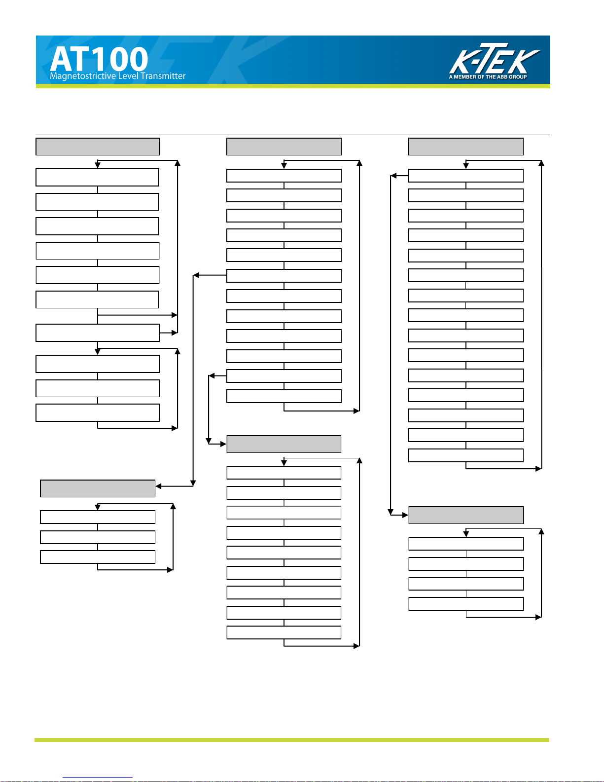
AT100 Menu Flow Chart
MAIN DISPLAY
LL1 - Liquid Level 1
L1C - Level 1 Current
LL2 - Liquid Level 2 1
L2C - Level 2 Current 1
TMP - Temperature 1
VOL - Volume 1
SET - Setup Menu
CAL - Calibration MENU
CFG - Configuration MENU
END
CAL - Calibration Menu
LRV - Lower Range Value
LRC - Lower Range Current 2
URV - Upper Range Value
URC - Upper Range Current 2
DAC TRIM - MENU
DMP - Dampening
LTT - Lower Temperature Trim 1
UTT - Upper Temperature Trim 1
LVV - Lower Volume Value 1
UVV - Upper Volume Value 1
VOL TABL - MENU 1
END
CFG - Configuration Menu
DE MENU - MENU 1
PV= - Process Variable 1
EUN - Engineering Unit
L1O - Level 1 Offset
L2O - Level 2 Offset 1
EUN TEMP - F/C 1
TMP RSET 1
VOL EUN 1
VOL MAN (or AUTO) 1
VMN - Volume Minimum 1
UTP - Upper Trim Point 1
VMX - Volume Maximum 1
ALD - Alarm Delay
VOL TABL 1
CCR - Custom Current Ranging 1
END
O01 - Output Point 1
DAC TRIM
D 4 - DAC Trim 4 mA
D20 - DAC Trim 20 mA
END
I01 - Input Point 1
O02, I02 through O19, I19
O20 - Output Point 20
I20 - Input Point 20
TBL SAVE
TBL LOAD
VST RSET
END
DE MENU 1
DE - On/Off
NV= - Number of Variables
DB - On/Off
END
To access a menu item press the SELECT button.
Use the UP and DOWN buttons to scroll through each menu and change the value of digits and menu entries.
Notes: 1. These items will only appear based on the ordered options of the transmitter.
2. Current ranging works only on Level (LU). Even though selected, volume uses 4-20mA.
AT100-0200-1 Rev L (10-2010) DCN0528 8
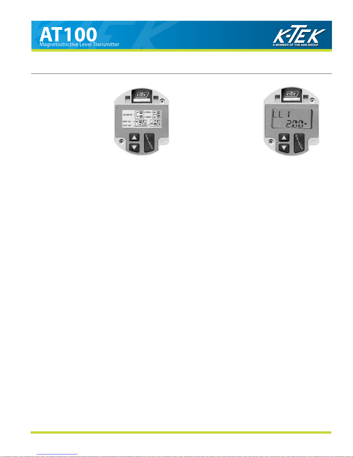
4.0 TRANSMITTER CALIBRATION AND SETUP
Electronics Without
LCD Display
Electronics With
LCD Display
4.4 Calibration Using the LCD Setup Menu
The LCD Display option offers a menu driven setup that uses the UP, DOWN and SELECT pushbuttons. Refer to
the menu flow chart for navigation and selection instructions.
Setting the 4mA point:
-Under the CAL menu, scroll DOWN to the LRV (Lower Range Value) menu option. Press SELECT to
change the value (in Engineering Units) for which the 4mA point is to be set.
Setting the 20mA point:
-Under the CAL menu, scroll DOWN to the URV (Upper Range Value) menu option. Press SELECT to
change the value (in Engineering Units) for which the 20mA point is to be set.
Note: The above steps can be repeated as many times as required. This procedure will only change the
calibration for the selected Primary Variable.
4.5 Selecting a Primary Variable (PV)
This section applies to dual-float transmitters only.
For a dual-float transmitter, the primary variable (LL1 or LL2) defines the float used to calculate current (mA) output.
If the primary variable is set to LL1, current output will be determined by the position of the float nearest the
transmitter housing. Alternately, if PV is set to LL2, current will correlate to the float farthest from the transmitter.
Selecting the Primary Variable
-Under the SET menu, access the CFG menu, then go to the PV= menu option.
-Press SELECT, then press UP or DOWN to cycle between LL1 and LL2 (the LCD will be blinking with your
selection).
-When the LCD is displaying the intended selection, press SELECT once more to set PV (the display should
stop blinking).
Note: If the Primary Variable is changed, it may be necessary to reset the 4 and 20 mA calibration points.
AT100-0200-1 Rev L (10-2010) DCN0528 9

4.0 TRANSMITTER CALIBRATION AND SETUP
4.6 Selecting an Engineering Unit for Measurement (EUN)
The unit is capable of displaying level output in inches, feet, millimeters, centimeters, meters, or in percent of
range.
Selecting an Engineering Unit
-Under the CFG menu, go to the EUN menu option.
-Press SELECT, then press UP or DOWN to cycle between engineering units.
-When the LCD is displaying the intended unit, press SELECT once more to set the engineering unit (the
display should stop blinking).
Note: Due to 4 digit display limitations on the display, if 9999mm will be exceeded, the metric engineering
units must be changed to cm.
4.7 Level Offsets (L1O and L2O)
Level Offsets can be utilized to make the indicated level on the transmitter match the actual level in your
tank or vessel. This is typically used to compensate for an un-measureable area at the bottom of the vessel. The
Level Offsets can also be utilized to make the indicated level on the AT transmitter match the indicated level of
another transmitter. Positive offsets will be added to the actual level of the transmitter to indicate a higher level.
Conversely, negative offsets will indicate lower levels.
Changing the Level Offset
- Navigate to the L1O (Level 1 Offset) menu option.
- Press SELECT to change the value (in Engineering Units) of the level offset to be applied.
- For dual-float units, Level 2 can be offset via the above steps with the L2O menu option.
4.8 DAC Trim
The output of the AT100 transmitters will be set up at the factory using calibrated multi-meters. Once
installed, the current output received by the control system will be influenced by the available power and field wiring
and may not indicate an exact 4.00 and 20.00 mA. To correct this error a DAC TRIM may be performed.
Performing the DAC Trim
-Under the CAL menu, scroll down to the DAC TRIM option
-Press UP and SELECT or DOWN and SELECT to enter the DAC TRIM menu
-At D 4 or D20 enter the current reading indicated at the control system and the transmitter will correct its
output
-Repeat each entry if needed then EXIT the menu.
4.9 Temperature Output
This section applies only to transmitters with the temperature output option. These transmitters will have
module types of M5A or M5B with or without a suffix of “D” or “F”.
4.9.1 Selecting the Unit of Temperature (EUN TEMP)
The unit will display temperature in either Celsius or Fahrenheit degrees.
Selecting the Unit of Temperature
-Under the CFG menu, go to the EUN TMP menu option.
-Press SELECT, then press UP or DOWN to cycle between Celsius and Fahrenheit.
-When the LCD is displaying the intended unit, press SELECT once more to set the temperature unit (the
display should stop blinking).
AT100-0200-1 Rev L (10-2010) DCN0528 10

4.0 TRANSMITTER CALIBRATION AND SETUP
4.9.2 Temperature Output Calibration
The transmitter is factory calibrated to an accuracy of ±0.5° Celsius, over a range of -200 to 300°C. Fine
calibration and trim for a custom range can be done via the following steps:
Setting the Lower Temperature Trim (LTT)
-Bring the sensor (located near the bottom of the transmitter probe) to the temperature that will be the lower
end of the temperature range.
-Under the CAL menu, go to the LTT (Lower Temperature Trim) menu option. Press SELECT to change
Setting the Upper Temperature Trim (UTT)
-Bring the sensor (located near the bottom of the transmitter probe) to the temperature that will be the upper
end of the temperature range.
Note: Trim must be within 10°C of factory calibration to be accepted.
4.9.3 Temperature Reset (TMP RSET)
If required, the unit‟s temperature settings (i.e. LTT and UTT) can be reset to the factory temperature
calibration. To reset the unit to the factory temperature calibration, navigate to the TMP RSET menu option and
press SELECT.
4.9.4 Temperature Master Calibration
The temperature indication of the AT100 will be factory calibrated from –200 to 300 degrees C. Under
normal circumstances, it will not be necessary to recalibrate the temperature transmitter. If for some reason
recalibration is required, the following steps will be used.
LTT to the current temperature of the sensor.
-Under the CAL menu, go to the UTT (Upper Temperature Trim) menu option. Press SELECT to change
UTT to the current temperature of the sensor.
1. Disconnect the power.
2. Setup decade box per drawing in Section 8 - Wiring Diagrams
3. Set resistance to 185 ohms.
4. Apply power.
5. Set EUN TEMP to °C (Celsius)
6. Cycle through CFG menu to END.
7. At END push UP and DOWN together.
8. At FAC –200 press SELECT then UP and DOWN at the same time.
9. Scroll Down to END and SELECT.
10. Verify TMP indicates -200°C.
11. Disconnect the power.
12. Set decade box for 2120 ohms.
13. Apply power.
14. Cycle through CFG menu to END.
15. At END push UP and DOWN together.
16. Scroll down to FAC 300.
17. Press SELECT then UP and DOWN at the same time.
18. Scroll Down to END and SELECT.
19. Verify TMP indicates 300°C.
20. Disconnect the power.
21. Reconnect RTD.
22. Reapply power.
AT100-0200-1 Rev L (10-2010) DCN0528 11

4.0 TRANSMITTER CALIBRATION AND SETUP
4.10 Volumetric Strapping
Note: For AT100 models with Strapping Table option only. If utilizing Foundation Fieldbus refer to section 4.3.5.2
for strapping table instructions.
4.10.1 How the Strapping Table Works
The AT strapping table works by using table points set up by the user. For every point, there is a volume
(provided by the user) and a measurement (provided by either the user or the transmitter). These table points are
used to map sensor measurement to volume output. As the float travels the length of the probe, the volume output
will change based on the two points in the table closest to the given transmitter measurement. With no points in the
table, the volume output is linear between VMN (volume min) at 0 measurement and VMX (volume max) at UTP
(upper trim point) which equates to the highest point of float travel. As points are added, the volume output is
extrapolated with respect to VMN, the table points, and VMX.
The Volumetric Table is capable of being set up in two different modes, Automatic and Manual. In
Automatic mode, as a volume point is entered, the position of the transmitter float will determine the transmitter
measurement associated with the volume entered. In Manual mode, as a volume point is entered, the user will be
able to modify the measurement to which the volume corresponds.
The points in the table are listed sequentially on the LCD as O01, O02, I02, … O19, I19, O20, I20. An „O‟ is
listed for each output point, which corresponds to volume. An „I‟ is listed for each input point, which corre-
sponds to linear measurement. If in manual mode, both output and input points will be available. In automatic
mode, only output points will be shown.
4.10.2 Setting Up (or resetting) the Strapping Table
Under the CAL menu:
-Scroll to VOL TABL, then press SELECT.
-Scroll up to VST RSET, then press SELECT. This will erase any table points currently set.
Under the CFG menu:
-Scroll down to UTP, (which stands for Upper Trim Point) and note the value listed.
-Scroll down to VMX (Volume Maximum).
-Enter for 0 as a value „0000‟, then press SELECT to reset the LCD decimal.
-Next, enter the value of the Maximum Volume corresponding to UTP. Note: Enter only the whole number
of the value, since the decimal is not present, then press SELECT.
-After the decimal has been placed, set any digits to the right of the decimal, if available.
-Scroll up to VMN (Volume Minimum).
-Enter the volume of the tank at 0 measurement on the transmitter probe.
4.10.3 Selecting the Input Mode (Automatic or Manual)
The AT transmitter provides two options for entering the values of the strapping table. The Automatic option
requires the level (or float) to be at the fixed location that corresponds to the selected volumetric output point
when the point is entered. If it is not possible (or feasible) for the tank level to be manipulated but a distance-tovolume conversion chart is available, the strapping table can be easily set up using Manual mode.
Under the CFG menu:
-Scroll down to VOL MAN or VOL AUTO (the LCD will display the current input mode).
-To switch between modes, press SELECT.
-Scroll UP or DOWN to change the mode.
-Press SELECT
AT100-0200-1 Rev L (10-2010) DCN0528 12

4.0 TRANSMITTER CALIBRATION AND SETUP
4.10.4 Setting Up Strapping Table Points
Under the CAL menu:
1) Scroll to VOL TABL, then press SELECT.
A) In manual mode, set the measured value for each Input Point and set the corresponding Output
Point to the desired volume value.
B) In automatic mode, position the float at the desired measurement point and set the
corresponding Output Point to the desired volume value.
2) Once the volume values and measurements are set in the table, scroll down to TBL SAVE and press
select. This will save the volume table in a backup location that may be recalled later by selecting TBL
LOAD.
4.10.5 Notes on Strapping Table Usage
The volume entered for any point must be between VMN (Volume Min) and VMX (Volume Max).
The measurement entered for any point must be between 0 measurement and UTP (Upper Trim Point).
A point may be removed („zeroed out‟) from the table by entering „0‟ for it‟s output „O##‟ field. If a point
is zeroed out, it will be bypassed when volume output is calculated.
A zeroed point may be set again, provided it is increasing with respect to the previous points in the table
list.
For all points in the table, all points must be increasing in volume and increasing in measurement, with
the exception of zeroed points. When setting up the table, points should be set up sequentially from
VMN (at 0 measurement) to VMX (at UTP);
It is not necessary to use all of the points in the Volume Table.
Since the table is based on VMN and VMX, any change to either of these will invalidate the table.
Therefore, once the table is properly set up, DO NOT change either of these settings.
4.10.6 Saving / Loading a Strapping Table
Because setting up the strapping table can be a time-consuming process, it is possible to save a copy of the
table, and also to load the table from a previous save.
To save the current strapping table:
Under the CAL menu:
-Scroll to VOL TABL, then press SELECT.
-Scroll up to TBL SAVE, then press SELECT.
To load a saved strapping table:
Under the CAL menu:
-Scroll to VOL TABL, then press SELECT.
-Scroll up to TBL LOAD, then press SELECT.
4.10.7 Setting Current Output Based on Volume
If the current output is to be based on volume:
-Under the CFG menu, scroll down to PV=.
-Press SELECT and scroll UP or DOWN to change the PV to VL1 (Volume 1) or VL2 (Volume 2) if
available. Selecting VL1 will filter the measurement from LL1 through the Volume Table, display
the result as the Volume (VOL) and output the current based on this volume. Selecting VL2 will
filter the measurement from LL2 through the Volume Table, display the result as the Volume (VOL)
and output the current based on this volume.
-Under the CAL menu, scroll down to LVV. Set this value to the volume that will correspond to 4mA.
-Scroll down to UVV. Set this value to the volume that will correspond to 20mA.
Note: LVV and UVV must be within VMN and VMX.
AT100-0200-1 Rev L (10-2010) DCN0528 13
 Loading...