

Page 1

18321 Swamp Road
Prairieville, Louisiana 70769 USA
Tel: (1) 225-673-6100 / Toll Free 800-735-5835
Fax: (1) 225-673-2525 / Toll Free 888-442-1367
Email: service@ktekcorp.com
Website: www.ktekcorp.com
Guided Wave Radar Level Transmitter
Installation and Operational Manual
MT2000-0200-1 Rev f (10-2007)
DCN0160
Page 2

TABLE OF CONTENTS
1. INTRODUCTION ................................................................................................................ 4
2. OVERVIEW ........................................................................................................................ 5
2.1 Storage Information ......................................................................................................................... 5
2.2 Ambient Temperature ..................................................................................................................... 5
2.3 Description & Principle of Operation ............................................................................................ 5
2.3.1 Direct Reflect Mode (standard) ..........................................................................................
2.3.2 Ultra Low Dielectric (ULD) Measure Method
3. INSTALLATION .................................................................................................................. 7
3.1 Mounting Requirements ............................................................................................. 7
3.2 Shortening of Probe .................................................................................................. 8
3.3 MT2000 Guided Wave Radar Guidelines ............................................................................ 8
3.4 Wiring
...................................................................................................................... 9
3.5 ATEX Approval Information ........................................................................................ 9
4. COMMISSIONING .............................................................................................................. 9
4.1 Quickstart Procedure ................................................................................................. 9
4.2 Verify Proper Power-Up ........................................................................................... 10
4.3 Setting the 4mA and 20mA Points Using the Pushbutton Menu ................................... 10
4.3.1 LCD Menu Operation ..................................................................................... 11
4.4 Detailed Configuration Parameters ........................................................................... 12
4.4.1 Direct Mode Blanking Parameter (BLK) .............................................................. 12
4.4.2 Threshold Level Parameter (THV) and Gain Setting (GS) ...................................... 12
4.4.3 Advanced Parameter Settings ......................................................................... 13
4.4.4 Ultra Low Dielectric (ULD) Mode Configuration .................................................... 15
4.5 Advanced Output Configuration ................................................................................ 16
4.5.1 DAC Trim .................................................................................................... 16
4.5.2 Setting the DAC Trim ..................................................................................... 16
4.5.3 Displayed Engineering Units (EUN)................................................................... 16
4.5.4 4 - 20 mA Output Damping (DMP) .................................................................... 16
4.5.5 Bench Calibration of the 4mA & 20mA Points ...................................................... 17
4.5.6 4mA & 20mA Calibration Using Actual Level Input ............................................... 17
4.5.7 Reversing the Output Action Using Actual Level Input ........................................... 18
4.5.8 Jumper Switch Settings .................................................................................. 18
5. TROUBLESHOOTING INFORMATION ........................................................................... 19
5.1 Valid Current Loop Outputs ...................................................................................... 19
5.2 Possible Symptoms ................................................................................................. 19
5.3 Electronics Module Replacement .............................................................................. 20
6. HONEYWELL DE OUTPUT OPTION ............................................................................... 20
6.1 Interoperability and Conformance Class .................................................................... 20
6.2 Operating Modes..................................................................................................... 21
7. HART PROTOCOL INTERFACE OPTION ....................................................................... 21
7.1 268 ROSEMOUNT Communicator ............................................................................ 21
7.2 HART AMS ............................................................................................................. 21
7.2.1 Compatibility ................................................................................................ 21
7.2.2 Resource Files ............................................................................................. 21
8. GLOSSARY OF TERMS .................................................................................................. 22
......................................................... 6
5
2 MT2000-0200-01 Rev f (10-2007)
DCN0160
Page 3

TABLE OF CONTENTS (CONTINUED)
9. APPENDICES ................................................................................................................ 23
9.1 APPENDIX A: Sensor Trim ............................................................................................. 23
9.2 APPENDIX B: Additional Special Functions in the CFG2 (Hidden) Menu.......................
9.3 APPENDIX C: Linearization ............................................................................................
9.4 APPENDIX D: Interface Applications ..............................................................................
9. 5 APPENDIX E: Oscilloscope Use & Setup for Troubleshooting ....................................... 28
9.5.1 General Setup ............................................................................................. 28
9.5.2 Use and Setup of the Oscilloscope for the MT2000 .............................................. 28
9. 6 APPENDIX F: CE Certification of Conformity .................................................................. 29
9. 7 APPENDIX G: Exida Certificate .....................................................................................
9.8 APPENDIX H: Installation Drawings for Intrinsic Safety & Standard Wiring .................... 31
9.9 APPENDIX I: Mounting Configurations
9.10 APPENDIX J: Warranty Statement ........................................................................ 35
..................................................................... 34
24
26
27
30
Figure 2.1 Direct Reflect Mode ............................................................................................... 6
LIST OF FIGURES
Figure 3.1 Mounting Requirements ........................................................................................ 7
Figure 3.2 Factory Default Configuration ................................................................................ 8
Figure 4.1 Quikstart Procedure ............................................................................................. 10
Figure 4.2 Electronics LCD Display ...................................................................................... 10
Figure 4.3 Transmitter Configuration from Model Number ................................................... 12
Figure 4.4 L10 Advanced Parameter Settings ...................................................................... 13
Figure 4.5 Ultra Low Dielectric (ULD) Mode Configuration ................................................... 16
Figure 4.6 Example of Display in Calibration Mode .............................................................. 18
Figure 4.7 Write Project (right jumper) .................................................................................. 18
Figure 9.1 Sensor Trim (Factory Defaults) ........................................................................... 23
Figure 9.2 Configuration 2 (hidden) Menu ............................................................................ 24
Figure 9.3 MT2000 Interface ................................................................................................ 27
Figure 9.4 Oscilloscope Use & Setup for Troubleshooting ................................................... 28
Figure 9.5 Mounting Configurations ...................................................................................... 31
MT2000-0200-1 Rev f (10-2007)
DCN0160 3
Page 4

1.0 INTRODUCTION
Thank you for using the K-TEK MT2000 Guided Wave Radar Transmitter. The MT2000 has been designed for ease
of use and to offer extensive configuration capabilities. You are urged to review this manual in its entirety prior to
use. This will eliminate most installation problems due to improper configuration.
We, the K-TEK Family, sincerely hope you receive many years of reliable use from this transmitter and welcome
your feedback to consistently improve our products.
When it comes to measuring the level of bulk solids, liquids, and everything in between, guided wave radar technology now offers more level-detection capabilities than ever before. For an ever-widening range of previously hard-tomeasure products such as molten sulfur, liquid ammonia and petrochemicals, guided wave radar transmitters provide accurate level measurements even under harsh chemical environments, wide variations in operating temperatures and pressures, and low dielectric constants. Great strides have also been taken in making these units easier
to configure to a variety of process applications coupled with the simplicity of integrating these devices with most
digital communication protocols. These improvements come as welcome relief to process engineers within an expanded range of level applications across several different industries that seek solutions to measuring the contents
of tanks, silos, hoppers, bins, mixing basins, and vessels.
Because radar transmitters have no moving parts, radar has already established a dominant niche in level measuring that quickly distances itself from mechanical means, which don't hold up as well in dirty service. Radar achieves
its non-mechanical level detection capability by measuring the time of flight of the transmitted signal.
Known more accurately as Time Domain Reflectometry (TDR), the process involves:
1. Sending microwave energy down into a vessel.
2. When the pulse of radar energy reaches the product (indicated by a change in impedance), part of the
pulse is reflected back toward the transmitter.
3. A receiver measures the exact duration of time between the transmitted and reflected signal—the "time
of flight."
4. The device analyzes this time and ultimately displays the level of the product as a distance in feet, meters, or other engineering units.
Through-air technology clearly pioneered the way for radar in terms of level measurement. However, one of the major problems of non-contact (with the product to be measured) through-air radar is the high probability of false echoes. Simply pointing a radar transmitter toward the bottom of a silo allows unguided waves to bounce off the sides
of the vessel itself, returning many divergent signals that must be canceled out at the receiving end. Part of the
problem stems from the wide dispersion of radar beams, which radiate away from the transmitting antenna in the
shape of an ever-widening cone. A similar problem also presents itself in ultrasonic measurements where divergent
angles of up to 20 degrees are routine.
These obstacles have now been overcome with the arrival of guided-wave radar transmitters. While fundamentally
relying on the same conventional time-of-flight technology used in through-air radars, guided-wave radars go one
step further by controlling the spread of radar beams via a "probe" that is introduced directly into the product to be
measured. Typically, the wave-guide is a specially designed metal rod or cable. Since the guide concentrates the
radar signal within a small-diameter (often less than 12 inches) cylinder along the probe, it doesn't disperse and reflect off materials that are not representative of product level. This results in a higher level of performance and reliability from the guided-wave device. Furthermore, the ease of configuration eliminates wasted time, as the need no
longer exists to spend time programming a unit to ignore erroneous readings from the sides o f the tank.
The advantages to guided-wave radar clearly play out when it comes to meeting the real-world challenges faced by
engineers in correctly determining product levels within storage and processing containers.
4 MT2000-0200-01 Rev f (10-2007)
DCN0160
Page 5

2. OVERVIEW
2.1 Storage Information
If required, storage prior to installation should be indoors at ambient temperature, not to exceed the following:
Temperature range: -40 to 150 degrees F.
Humidity: 0 to 100% R.H. non-condensing.
2.2 Ambient Temperature
The MT2000 electronics temperature may not exceed 170°F / 77°C. For higher ambient temperatures, a high temperature option extension is required. The probe process temperature shall not exceed the temperature stated in
the specifications for the given coupler.
2.3 Description & Principle of Operation
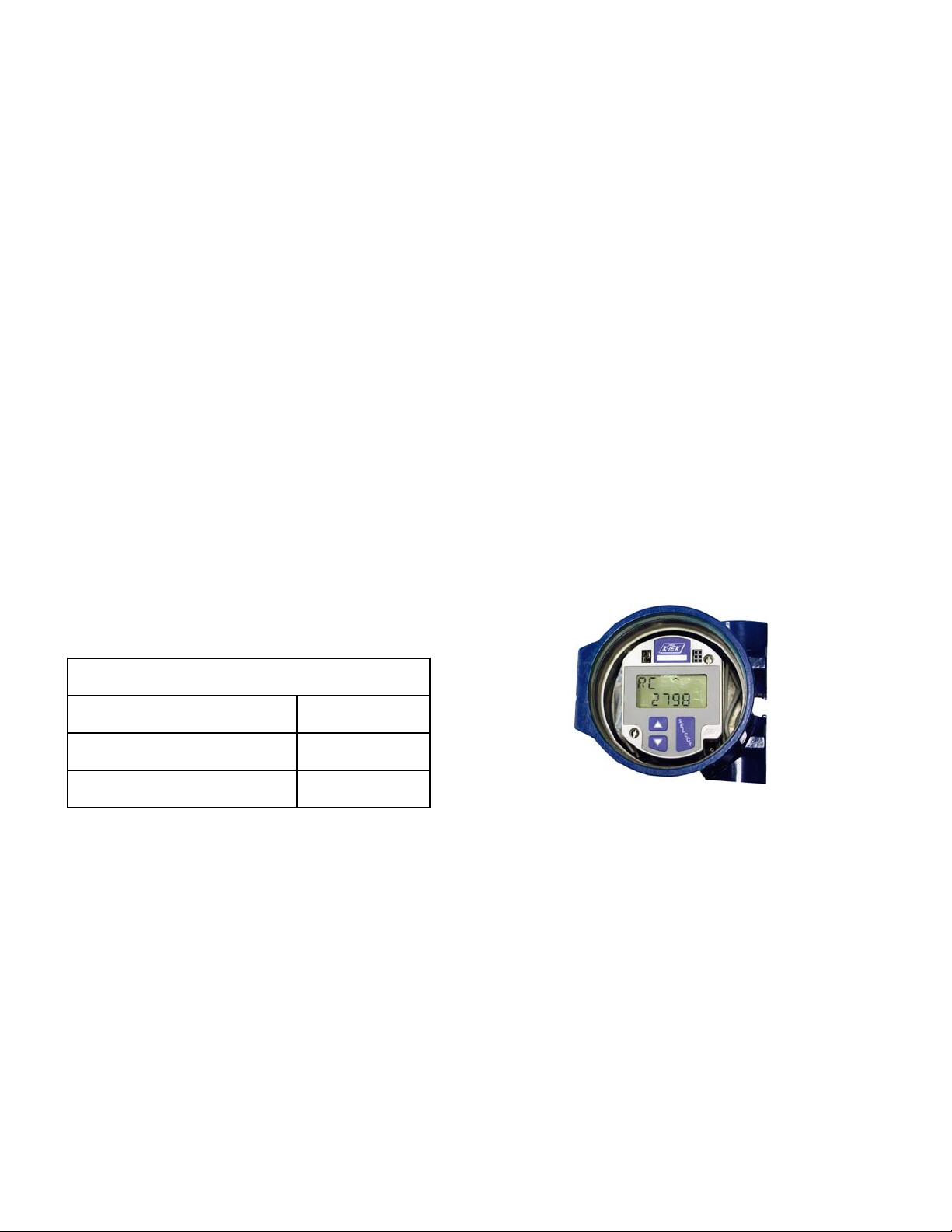
2.3.1 Direct Reflect Mode (standard)
The MT2000 is a 4-20mA loop powered Smart Level Transmitter, which is microprocessor based and is available
with HART or Honeywell DE digital output. It uses very low power microwave energy to determine the level of the
product being measured. In order to obtain optimum performance, it is important to understand the basic principle of
operation. The electronics housing is typically fitted with a special adapter “Coupler” serving as a process connection
and seal, and holding a solid rod or a cable. The rod or cable “Probe” hangs into the vessel and acts as a waveguide, i.e. the microwave energy stays concentrated around the probe and along its length, instead of being dispersed in a cone, as it would be if there was no probe.
A measurement cycle consists of the following:
1. A very short “pulse” of microwave energy is applied at the coupler, to the Probe.
2. The pulse travels along the length of the probe and when it encounters a discontinuity that is a dielectric constant change, such as the product surface, some of the energy is reflected and travels back towards the coupler.
3. When the reflected energy reaches the coupler, it is sensed by the electronics. By measuring the time elapsed
between the initial pulse and the reflected one, the electronics can calculate the product level.
4. Since the microwave energy travels at the speed of light, one complete measurement cycle is made up of several thousands of Pulses. The electronics uses Time Domain Reflectometry (TDR), a sampling technique to reconstruct a waveform duplicating the actual real time signal, but at a much lower speed, so that it can be processed by the microprocessor. This process can be compared to using the stroboscope effect as when observing
a piece of machinery turning at high speed with a strobe light.
5. The measurement cycles are made 10 times per second and processed by special filtering techniques, before
generating a current output proportional to the level of the product.
A simplified signal trace as seen on an oscilloscope (Figure 2-1) can be divided into four identifiable sections:
- Start Pulse.
- Coupler Reflection.
- Signal Reflection
- End of Probe Reflection
MT2000-0200-1 Rev f (10-2007)
DCN0160 5
Page 6

2.3.1 Direct Reflect Mode (standard) (cont’d)
The measurement principle using TDR is based on the fact that a dielectric constant discontinuity or geometric
change will yield a negative pulse having certain amplitude below the baseline. The greater the dielectric constant
difference, the greater the negative amplitude of the return signal. This means that a signal will show up on the
baseline if there is a substantial change from a nozzle diameter to an open tank, for example, as signal plot at the
process connection. This fact needs to be taken into account in order to configure the MT2000 properly (Consult
section on commissioning).
Displayed in Figure 2.1 is the return signal, as one would see it on an oscilloscope. Refer to troubleshooting section
for oscilloscope set up. Abbreviations used are:
GS Gain Setting BLK Blanking
THV Threshold Voltage URV Upper Range Value (20 mA)
LRV Lower Range Value (4 mA) LL1 Liquid Level 1
L1 Unmeasurable Zone (Top of Probe) L2 Unmeasurable Zone (End of Probe)
Figure 2.1
2.3.2 Ultra Low Dielectric (ULD) Measure Method
To effectively measure the level of very low dielectric products a different methodology is needed due to the poor
reflection of the pulse on the surface of the product. This reflection is not strong enough to make a reliable level
measurement. To achieve reliable and precise measurement the MT2000 uses the Ultra Low Dielectric (ULD)
measurement method. This method requires the use of a flexible cable utilizing a weight / target assembly at the bottom end of a precisely known length. The pulse travels through the air at a known velocity and then passes through
the product at a reduced velocity depending on the product dielectric constant.
Note: Reference Section 4.4.4 for ULD Mode setup and configuration.
6 MT2000-0200-01 Rev f (10-2007)
DCN0160
Page 7
3. INSTALLATION
3.1 Mounting Requirements
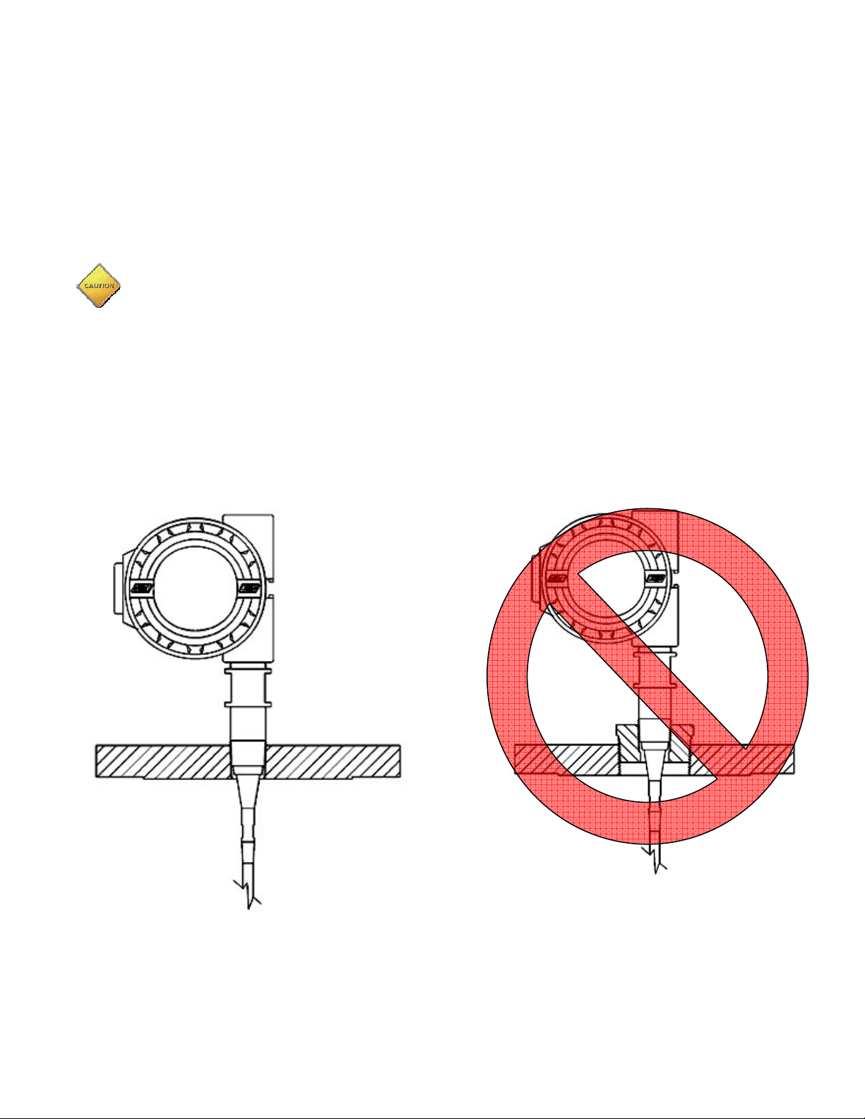
IMPORTANT: To obtain the best return signal from the product level it is recommended to mount the MT2000 cou-
pler directly into the top of the vessel if the vessel material is metal, or into a metal plate if the vessel is non-metallic.
A flat metal surface perpendicular to the probe acts as a “launch plate”, minimizing the loss of microwave energy
from dispersion (Figure 3-1). When this configuration is not practical the MT2000 can be installed in flanged nozzles,
as long as the mounting details are taken into account. Please refer to the recommended mounting information as
described in Appendix I “Mounting Configurations”.
CAUTIONS:
1. The housing cover can only be removed when the unit is installed in a non-hazardous area, when installed with intrinsic safety barrier, or when power is removed from the transmitter.
2. Tanks constructed of concrete additionally require probe mountings be:
a. 1 ft. / 0.3 m from wall with up to 20 ft. / 6.1 meter measuring length.
b. 2 ft. / 0.61 m from wall over 20 ft. / 6.1 meter measuring length.
CORRECT
MT2000-0200-1 Rev f (10-2007)
INCORRECT
Figure 3.1
Figure 3‑1
DCN0160 7
Page 8

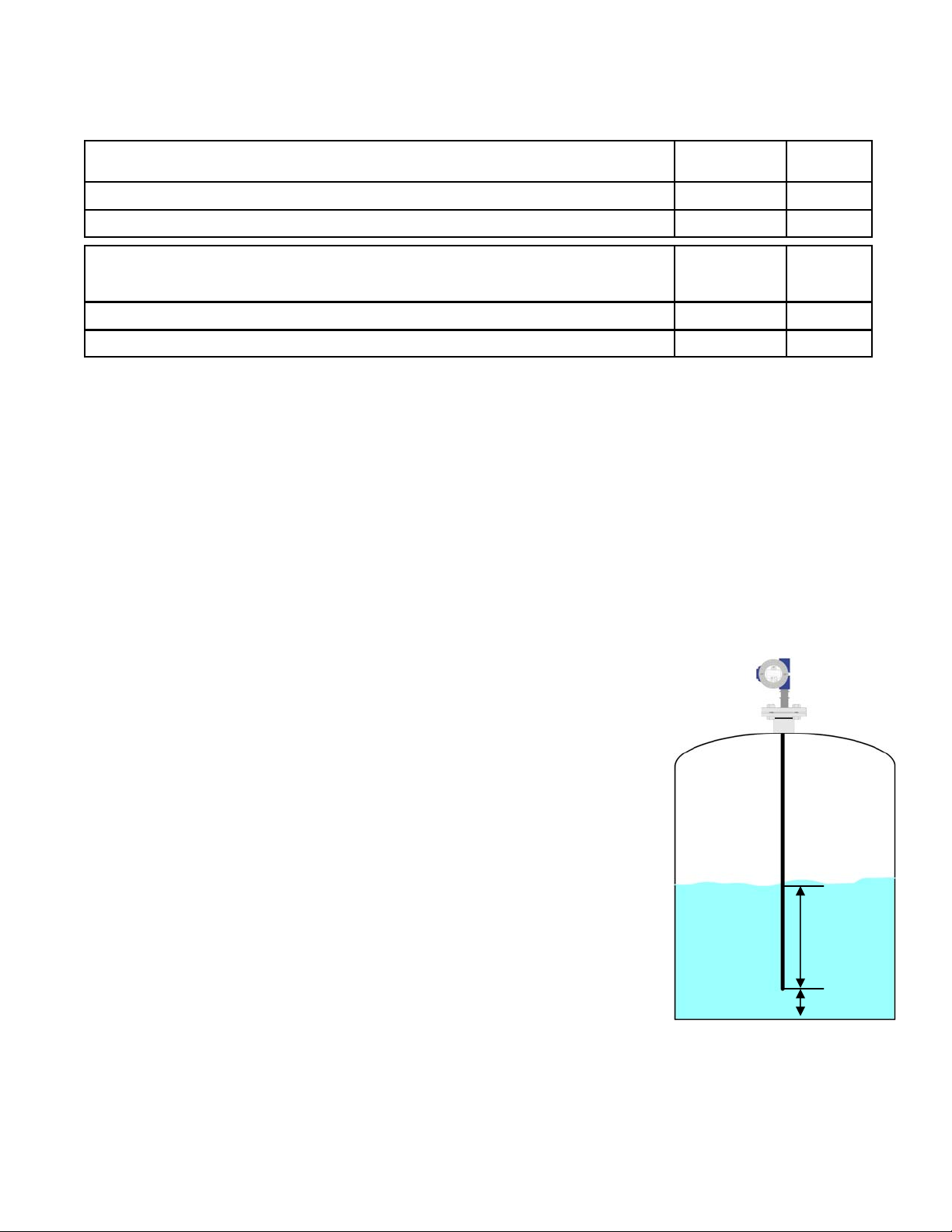
3.2 Shortening of Probe
The MT2000 single probe can be cut to length prior to installation. The MT2000 default factory configuration provides a measurement in engineering units with a zero referenced to the bottom of the sensing probe. The top of the
probe yields a measurement equal to the probe length (Figure 3.2).
20 mAdc
0 in / 0 mm
Probe Length
Factory Default Configuration
1. The default factory setup is with the instrument measuring “level”; This means that the display will indicate
URV = Probe Length
LRV = 0 in. / 0 mm
a number equal to the sensor length when the level is
at the top of the vessel. When the vessel is empty it
will indicate zero.
2. If readout in “level measurement units” is not desirable, engineering units can be set to percentage (%).
This will provide the readout in percentage of total
level, referenced to the 4 mA and 20 mA points (LRV
and URV).
3. If percentage (%) tank level readout is not desirable,
4 mAdc
Cable Length
0 in. / 0mm
proceed to Sensor Trim Section (Appendix A).
Figure 3.2
If the probe is shortened, the unit will indicate the distance as if the level was at the place where the probe was cut
off as the lowest value, and read the change in EUN correctly FROM THAT POINT— to the URV.
Example: MT2000 was shipped (and trimmed) with a 10ft. probe. The probe was shortened by removing 3ft. leaving the total length at 7.0 ft. If the transmitter was installed with no further correction, the transmitter display (LL1)
will indicate 3.0 ft. with the level at the end of the probe and 10ft. with the level at the top (a change of 7ft.). To set
the transmitter to transmit 4 – 20 mA over the length of the probe, the following settings would need to be entered in
the CAL menu:
LRV = 3.0 ft and URV = 10.0 ft.
If this is not desirable, one of the following can be done:
1. Change EUN = %. The level will now be shown (LL1) as 0.0% to 100.0%. (Note: LRV = 3.0 ft.; URV = 10.0 ft.
in this example.)
2. Enter L1O = -3.0 ft. The unit will now display 0.0 ft to 7.0 ft for the above 7.0 ft level change. LRV and URV
must be set (LRV = 0.0 ft., URV = 7.0 ft.) accounting for the offset, matching the display (0.0 to 7.0 ft).
3. Re–trim the unit to the actual sensor length – see Sensor Trim Section (Appendix A).
3.3 MT2000 Guided Wave Radar Guidelines
These guidelines are not absolute limits but rather limits that will ensure optimum performance and ease of configuration:
Cable sensor probe is preferred over rigid rod.
Cables in tube or Pipe:
• Use P11 (3/16” DIA) cable.
• In 3” Pipe: 10 Ft. Max cable without spacers, longer cable with spacer every 10 ft.
• In 1.5” or 2” pipe: 7 ft. max cable without spacers, longer cable with spacer every 5 ft.
• Three spacer sizes available for 1.5”, 2”, or 3” sch 160 pipe.
• Two spacer materials available, Teflon and ceramic (above 400°F).
8 MT2000-0200-01 Rev f (10-2007)
DCN0160
Page 9

3.3 MT2000 Guided Wave Radar Guidelines (cont’d)
Rods:
• 1/4”rod 5 ft. max, minimum 3” Dia. Stilling well if provided with stilling well.
• 1/2” rod 10 ft. max, minimum 3” Dia. Stilling well if provided with stilling well.
• In 2” pipe: 5ft. Max 1/4” or 1/2” rod.
Coaxial:
• C8 and C9 with rigid rod always fully assembled with sensor well from factory.
3.4 Wiring
Install conduit to ½” NPT port and run 18 gauge twisted, shielded pair to housing. Refer to attached wiring diagram
on page 33 for typical loop wiring diagram and pg 31 for instructions applicable to intrinsic safety installation
(Appendix H).
Apply loop power to the transmitter as follows:
Terminal Block + 14 Vdc minimum to 36 Vdc Maximum
Terminal Block - To control System Input
Ground Screw GROUND
Note: The “+Meter” and “-Meter” terminals are available to hook up a mA meter to monitor loop current, without
breaking the loop.
3.5 ATEX Approval Information
Special Conditions for Safe Use
4. COMMISSIONING
Mounting: Installation and cable types used shall be in accordance with EN50-039 and the relevant codes of practice.
Wiring:
The supply to the MT 2000 unit must be fed through a suitable Certified barrier/isolating interface mounted
in the safe area.
4.1 Quickstart Procedure
An MT2000 from the factory will be set with several default parameters. These parameters have been selected to
cover the widest range of dielectric constants (typical water based products) and in some cases no adjustments will
be necessary.
Each unit will be trimmed with 0 inches at the end of the probe and a distance equal to the probe length at the face
of the coupler. The calibration range will be set with 4mA at the end of the probe and 20 mA at the face of the coupler. For instance, In Figure 4-1, a 25-foot cable probe will indicate 300 inches and 20 mA at the top while indicating
0 inches and 4mA at the bottom. With this knowledge in hand, an MT2000 can be installed quickly and easily.
1. Remove all of the pieces of the MT2000 from the packaging and assemble them, if necessary.
2. Install the transmitter into its process connection and proceed with wirin g. (See section 3.3 field wiring).
3. Power up the unit. All of the digits on the display will light up. The output from the transmitter will drop to 4mA,
then start to climb to the level of the product.
4. Enter the Calibration menu using the pushbuttons on the faceplate. Select and set values for LRV (4mA) and
URV (20mA).
5. When this is complete, the unit should be functioning and ready for normal operation.
If the output does not correspond with the level or does not change with the level movement, proceed to section 4.2.
MT2000-0200-1 Rev f (10-2007)
DCN0160 9
Page 10

4.1 Quickstart Procedure (cont’d)
URV= 20mA
300 in. / 7620 mm
LRV = 4 mA
0 in. / 0 mm
CAL
CFG
Raw Counts
HTP = 288”
2565 2100
BLK = 210
LTP = 6”
13272
Figure 4.1
4.2 Verify Proper Power-Up
Apply power to the transmitter and verify that the display comes up and is active. The display update rate is approximately 4 seconds. The current draw should under no case exceed 21 mA and, in the event of a problem, refer to
trouble-shooting section.
4.3 Setting the 4mA and 20 mA Points Using the Pushbutton Menu
The LCD Display (Figure 4-2) option offers a menu driven setup that uses the UP, DOWN and SELECT pushbuttons. Refer to the menu diagram (following this section) for navigation and selection instructions.
Note: The default factory setup is such that the instrument measures liquid level; i.e. the display will indicate a num ber equal to the sensor length when the level is at the top of the vessel, and will indicate a zero when the
vessel is empty.
• Setting the 4mA point:
Under the CAL menu, go to the LRV (Lower Range Value) menu option. Press SELECT to change the value (in En-
gineering Units) for which the 4mA point is to be set. With the default factory setup, LRV is typically set to or near
zero engineering units.
• Setting the 20mA point:
Under the CAL menu, go to the URV (Upper Range Value) menu option. Press SELECT to change the value (in
Engineering Units) for which the 20mA point is to be set. With the default factory setup, URV is typically set to or
near the actual probe length.
Note: The above steps do not require changing the level in the vessel.
Title
Electronics LCD Display
Engineering Units or
Calibration Mode
4 digit
Display
UP
Button
DOWN
Button
SELECT
Button
Figure 4.2
10 MT2000-0200-01 Rev f (10-2007)
DCN0160
Page 11

4.3.1 LCD Menu Operation
The LCD display is menu driven, uses the UP, DOWN, and SELECT pushbuttons for navigation.
• Press UP or DOWN to scroll through menu options.
• Press SELECT to select a menu option.
• When changing a variable use SELECT to move between signs or digits. When all digits flash an invalid value
has been entered; press SELECT to continue
POWER UP
Auto-Scroll Mode
LL1
Liquid Level 1
L1C1Level 1 Current
(Press SELECT to exit Auto-Sc r o ll Mode)
MAIN MENU
SET
Enter Setup Menu
LL1
Liquid Level 1
L1C
Level 1 Current
DE Output %
SETUP MENU
CAL
Enter Calibration Menu
CFG
Enter Configuration Men u
END
Exit Setup Menu
LINEARIZATION MENU
O01
Output Point 1
O02
Output Point 2
O20
Output Point 20
LIN SAVE
LIN LOAD
LIN RSET
END
Save Linearization Tabl e
Load Linearization Table
Reset Linearization Table
Exit Linearization Menu
CALIBRATION MENU
LRV
Set Lower Range Value (at 4mA Po int)
URV
Set Upper Range Value (at 20mA point)
DMP
Set Damping Value (.1 to 36 Sec)
DAC TRIM †
LIN MENU
END
Exit Calibration Menu
DE Menu (if ordered)
EUN
Set Engineering Units
(In, ft, mm, cm, m or %)
L1O
Set Level 1 Offset
KO
Module Offset
KG
Module Gain
THV
Threshold Voltage
RC(1)
Raw Counts
BLK
Blanking Value
GS
Gain Settings
LCH
Latching Settings
DRC
Downward Restriction Coun t
ALD
Alarm Delay
END
Exit Configuration Menu
Enter DAC Trim Menu
Enter Linearization Menu
CONFIGURATION MENU
3
DE Menu (optional)
DE ON/OFF
DB ON/OFF
END
1. Press DOWN & SELECT together for 4mA trim or UP & SELECT together for 20 mA trim
2. Available on DE output models only.
MT2000-0200-1 Rev f (10-2007)
2
Turn DE output ON
Extended Informati on
Exit DE Menu
To LL1
CONFIGURATION MENU 2
RNG
LTP
HTP
END
Range Setting
Lower Trim Point
High Trim Point
Exit Configuration Menu 2
*To access this menu see
"Setting LTP & HTP"
DCN0160 11
Page 12
4.4 Detailed Configuration Parameters
4.4.1 Direct Mode Blanking Menu
Note: This section only applies to direct mode measurement.
The blanking parameter (BLK) is used to ignore an extended nozzle that would otherwise cause a reflected signal at
the top of the probe and result in a high level reading even when no product is in the vessel.
For probe configuration 1,2,5,6 or 7 (Appendix G) use the factory default BLK.
BLK can be changed by accessing SET followed by the CFG menu (refer to menu chart). If the MT2000 is installed
in an extended nozzle or other configuration where the top of the tank is further than 1 inch from the probe coupler
set BLK as follows:
For probe length < 100 ft. (30.5 m) add 4 to the BLK value for every 1 in (2.5 cm) of tank nozzle
For probe length ≥ 100 ft. (30.5 m) add 2 to the BLK value for every 1 in (2.5 cm) of tank nozzle.
Example: RS=1: Nozzle length = 10” BLK=200 + 4(10) = 24 0
To verify settings are correct, proceed to CFG menu. Scroll down to RC (Raw Count) value display. RC (Raw
Count) will decrease as levels rises and increase as level lowers. Caution: if RC value exceeds 4 digits, then the first
digit is shown on the top line of the display.
If RC stays at a fixed low value around 2000 while the level changes the BLK is set too low and needs to be adjusted. Raise the level and stop when RC stops decreasing or top of the vessel is reached, whichever comes first. If
RC stops decreasing before the top level is reached reduce the BLK.
To determine the actual level using Raw Counts use the following formula:
(RC – 2100) / 38 = Distance in inches
(Distance x 38) + 2100 = Expected Raw Counts (RC)
Typical BLK Factory settings:
Transmitter Configuration from Model Number
Range
/L Local Option
Probe length < 100 ft. / 30.5 m BLK = 210
Probe length ≥ 100 ft. / 30.5 m BLK = 110
Figure 4.3
4.4.2 Threshold Level Parameter (THV) and Gain Setting (GS)
The threshold level and gain settings are used to fine tune the detection of products with different dielectric constants, and to adapt to different probe configurations. THV is typically set between 1.0 to 1.8.
Note: Lower THV values make the transmitter less sensitive and higher THV values make the unit more sensitive to
lower dielectrics. GS is typically set to 2 or 4. GS = 1 is lower gain than GS = 2, and GS = 3 is lower Gain than GS =
4.
For probe configurations 1,2,3a, and 3b (Appendix G), with a dielectric constant above 10 use the factory default
settings THV=1.5, GS=2.
For probe configurations 4,5,6,7,8,9,10a, 10b, THV settings of 1.65 ± 0.15 are typical, depending on fluid dielectric
constant using GS = 4.
12 MT2000-0200-01 Rev f (10-2007)
DCN0160
Page 13
4.4.2 Threshold Level Parameter (THV) and Gain Setting (GS) (cont’d)
The following values should be used as starting points:
For Mounting Configuration 1,2,3a and 3b, (direct insertion in tank - no stilling well
applications, no coaxial probes) with the following dielectric constant:
≥ 10
≥ 3 and < 10
For Mounting Configuration 4,5,6,7,8,9,10a & 10b with the following dielectric
constant: (ground plane probe / installation applications - coaxial probes stilling
well, EC chambers)
≥ 10
< 10
*Factory Default
Assuming the 4 mA point is set toward the bottom end of the probe and that the 20 mA point is set toward the top,
for a given GS setting:
• If THV is set too high the output will either read high or spike high.
• If THV is set too low the output will either read low down to 3.8 mA, spike low, or be in fault high (21mA) or fault
low (3.6mA).
• Adjust THV as needed to obtain a steady output reflecting the actual level over the usable measuring range.
NOTE: If a stable output cannot be obtained, refer to trouble-shooting section or to Appendix F for viewing sensor
signal using an oscilloscope.
GS THV
2* 1.5*
2 1.7
GS THV
4 1.0
4* 1.7*
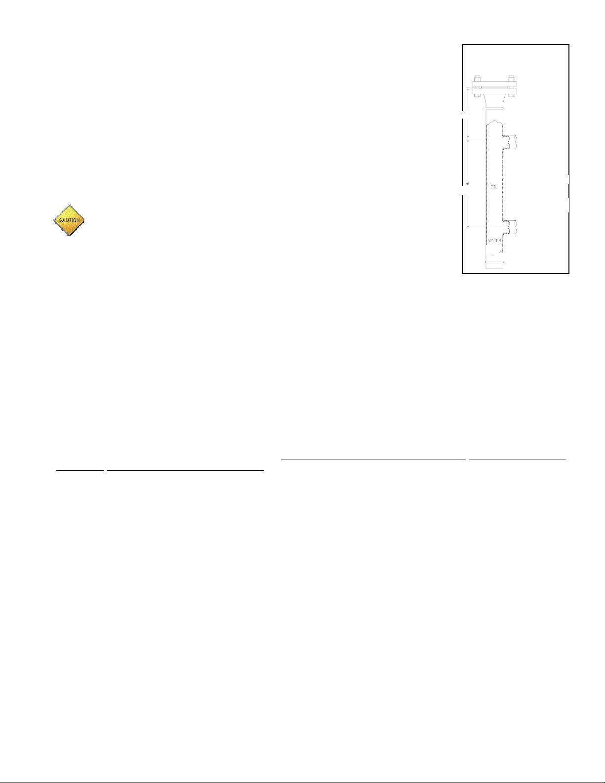
4.4.3 Advanced Parameter Settings
• L1O
Level One Offset is used to offset the level output of the transmitter to match the
actual level in your tank or vessel. This offset allows the transmitter to be calibrated
so that the 4mA is equal to a value higher than zero. There are several cases when
Level Offset can be used:
1. To accommodate for a non-measurable length at the bottom of the
probe.
2. To accommodate for the length of the probe being shorter than the ac-
tual length of the tank or vessel due to agitator or other devices near the
bottom.
3. To synchronize two redundant transmitters
4. To allow a zero-based measured variable which is used when an EC
measurement needs to correlate locally to a sight glass. It also simplifies setting the range (from tap to tap)
L1O can be positive or negative and as much as 50% of the sensor trim span (HTPLTP). Figure 4.4 shows a typical L1O offset.
Example: If the end of the probe, in Figure 4-4, were 4 inches off the
bottom of the tank the L1O Level Offset would be 4. If the Measured Level
were 21 inches then the local indicator would indicate 25 inches (21 +4) and
the 4-20 mAdc signal would indicate a level of 25 inches. This will provide
local indication and signal of the actual level of 25 inches.
Figure 4.4
Measured
L1O
MT2000-0200-1 Rev f (10-2007)
DCN0160 13
Page 14

4.4.3 Advanced Parameter Settings (cont’d)
• KO & KG
KO and KG parameters should only be changed during the replacement of an electronic module. Refer to
troubleshooting section
• LCH
For Devices configured to measure 0 at the end of the probe, this value defines the sensitivity of the Latching
feature. When this feature is enabled, and the detected signal extends past the end of the probe, the resulting
output is “latched” at 0, until the signal is again detected at the end of the probe. To disable this feature, set this
value to 0. If your application has a use for this feature, it is recommended that this value be set to “20” for RNG=1,
and “10” for RNG=2. If this value is not sufficient for the latching to take effect, lower this value as necessary.
• DRC
This feature is used in conjunction with the latching feature to determine the ease with which the output may become
unlatched. With this value enabled, the return signal must be detected above a certain point near the end of the
probe, identified by DRC. To disable this feature, set it to 0. To enable this feature, set the value to 40
(recommended). For turbulent processes, raise this value as necessary.
• ALD
Alarm Delay specifies the time (in seconds) an alarm condition will be ignored before the module enters its
condition (Hi or Lo, according to the FAULT HIGH/LOW jumper settings). Any condition generating an alarm (loss of
echo) must last longer than the specified amount of time before the transmitter’s output will be affected. During the
ALD timing period, the transmitter’s output is held steady at the last good signal. If the alarm condition clears before
ALD times out, the transmitter assumes normal operation. If the time delay is fulfilled without the alarm condition
clearing, the transmitter’s output goes immediately (by passing all output damping settings) into the fail condition
selected by the jumpers on the module face (Hi = 21 mA / Lo = 3.6 mA).
The primary use for this function is to compensate for applications that are typically low dielectric constant fluids and
that may be either boiling or flashing, causing a momentary loss of the signal echo. ALD will keep the process from
being upset, allowing the random condition to pass without impacting the transmitter’s mA output.
Notes:
• The DMP (transmitter’s output damping) parameter is bypassed when the alarm delay (ALD) time out.
• When the alarm condition clears, DMP is again bypassed and the output goes directly to the value gen-
erated by the level.
• Factory default setting is for ALD 2.0 seconds.
• RNG
All sensors with a measuring range less than 100 ft. / 30.5 m use the factory default value RNG=1 and do not require
changing this parameter. For a measuring range greater than 100 ft. / 30.5 m, RNG should be set to RNG = 2 by
accessing factory menu setup (Refer to menu chart).
• LTP
Sensor Trim "Lower Trim Point" defines a point on the sensor at which the display will indicate the value entered for
LTP. Refer to Appendices Section for Sensor Trim instructions.
• HTP
Sensor Trim "High Trim Point" defines a point on the sensor at which the display will indicate the value entered for
HTP. Refer to appendices Section for Sensor Trim instructions.
Note: When performing a Sensor Trim (Appendix A), one defines how the device makes measurements, in term of
Engineering Units, at 2 points on the sensor. All other level points on the sensor are derived from a linear formula
passing through LTP and HTP.
alarm
14 MT2000-0200-01 Rev f (10-2007)
DCN0160
Page 15

4.4.4 Ultra Low Dielectric (ULD) Mode Configuration
Note: Use this method for very low dielectric solids only, when little or no usable signal can be obtained from the
product surface. Use in solids measurement applications with 1.3 < DC < 2.0. If the DC is above this 2.0 value
please contact the factory for application support. Special calibration of the Trim Points is required.
1. The dielectric constant of the material must be stable and below 2. If the dielectric constant is above 2 and the
MT2000 cannot be operated reliably in the direct reflect mode; the ultra low dielectric mode of measurement
may be used if the target at the end of the probe/cable can be detected reliably with the vessel full. We recommend viewing the target reflection with an oscilloscope with the vessel full to verify that the measurement can be
made reliably.
2. A suitable target is required at the bottom end of the sensor probe/cable. A 3" minimum diameter centering disk
with holes is suitable, but needs to be on the cable, above any weight.
3. Set the Threshold Level THV = 1.5 V and the Gain Setting GS = 2
4. Set BLK to reject any signal above the target. Estimate BLK based on length of the probe/cable. BLK = 170 + L
* 3.8 (L in inches)
5. The following procedures assume that the MT2000 is set up with the factory standard trim values of zero at the
top of the probe.
6. If the product dielectric constant is known, calculate the desired LRV (4 mA point) and URV (20 mA point) values
with the following formula and example below:
I = indicated level on read out with factory standard trim (inches, ft, mm, cm or m)
H = actual or desired height above the target at the end of the probe/cable
L = length of probe/cable from the coupler to the target (same units as H)
DC = product dielectric constant
I = H * SQRT (DC) – H + L
Calculate I at the desired LRV and URV. Make sure that EUN (engineering units), with the exception of percentage
(%), are set at the same units used in the calculation. Enter the desired LRV and URV using the Calibration Menu of
the MT2000.
After the LRV and URV have been entered, change the engineering units to % so that the MT2000 display will indicate level relative to the vessel.
Example: Probe length (L) is 360” from the target to the coupler. The product dielectric is 1.4. Desired 4
mA point is 12” above the target (H=12”). Desired 20 mA point is 24” below the coupler (H=336”). See Figure 4.5.
LRV = H * SQRT (DC) – H + L URV = H * SQRT (DC) – H + L
LRV = 12 * SQRT (1.4) – 12 + 360 URV = 336 * SQRT (1.4) – 336 + 360
LRV = 362.20” URV = 421.56”
Set LRV and URV to these values, and then change EUN to %. If EUN are not changed to % the indicator
on the MT2000 will indicate 362.20” at 4 mA and 421.56” at 20 mA.
If the product dielectric constant is not known, establish a known level in the vessel. The most accurate results will
occur when the known level is as high a possible. Use the following formula to calculate the product dielectric constant:
I = indicated level on read out with factory standard trim (inches, ft, mm, cm or m)
H = actual or desired height above the target at the end of the probe/cable
L = length of probe/cable from the coupler to the target (same units as H)
DC = product dielectric constant
DC = ((I + H – L) / H)
After determining DC go to the previous Step 6 above to complete the setup.
2
MT2000-0200-1 Rev f (10-2007)
DCN0160 15
Page 16

4.4.4 Ultra Low Dielectric (ULD) Mode Configuration (cont’d)
Coupler
If it is not practical to establish a known level in the vessel before commissioning
the MT2000 a demo MT2000 with a short probe can be used in a small container of
the product to estimate the product dielectric constant with this procedure. If this
estimated DC is used, we recommend verifying it later with a known vessel level
that is as high as possible.
Example: Using the same conditions in Step 6, we establish a level 24” from the
top of the probe/cable (H = 336”). The readout on the MT2000 indicates 421.56”.
L
Calculate DC as follows (Refer to Figure 4-5):
DC = ((I + H – L) / H)
DC = ((421.56 + 336 – 360) / 336)
2
2
DC = 1.40
Note: LRV and URV can be calculated using the procedure in Step 6. (see page 15)
4.5 Advanced Output Configuration
4.5.1 DAC Trim
H
Figure 4.5
CAUTION: DAC Trim causes the output to change from reading level to a
fixed 4 ma or 20 mAdc. If this is done while unit is in operation, it can cause an alarm or shutdown.
The MT2000 Guided Wave Radar level transmitter is a truly digital transmitter. The 4 mA and 20 mA values are set
at National Bureau of Standards traceable values. At individual facilities the standard values may vary slightly.
DAC Trim is used to force the MT2000’s 4 mA and 20 mA points to agree with an external meter or measuring device. From DAC trim menu use the DOWN arrow and SELECT to set the 4 mA point and use the UP and SELECT
for the 20 mA point.
4.5.2 Setting the DAC trim
1. Connect an external meter or refer to measuring device for 4 mA point.
2. Press DOWN arrow and SELECT buttons together for one (1) second to select 4 mA point. Use select button to
scroll through numbers. Use UP and DOWN arrows to adjust the number to agree with meter.
3. Press UP arrow and SELECT buttons together for one (1) second to select 20 mA point. Use select button to
scroll through numbers. Use UP and DOWN arrows to adjust the number to agree with meter.
4. To exit DAC trim menu use the UP or DOWN arrows to scroll until END appears in LCD. Press SELECT and
the MT2000 will return to normal working mode.
4.5.3 Displayed Engineering Units (EUN):
The unit is capable of displaying level output in inches, feet, millimeters, centimeters, meters, or in percent of range.
• Selecting an Engineering Unit
• Under the CFG menu, go to the EUN menu option.
• Press SELECT, then press UP or DOWN to cycle between engineering units.
When the LCD is displaying the intended unit, press SELECT once more to set the engineering unit (the display
should stop blinking). If the transmitter will not accept the engineering units change attempting to be made, it indicates that there is an overflow in digits based on a value 50% greater than the sensor trim span {(HTP – LTP) x
150}. This is most likely to occur when attempting to change the existing EUN to mm (millimeters). The module will
not accept the new EUN and revert back to the previous EUN selection.
Note: If the engineering units (EUN) or any other number requires more than 4 digits to display, the most significant
digit will appear as the last digit on the top line, giving a possibility of displaying 5 significant digits up to 99999.
4.5.4 4 - 20 mA Output Damping (DMP):
Damping helps to reduce the affects of rapid or irregular movement of the fluid level in a tank or vessel. Damping
simply adjusts the time between readings. A higher number allows for more stability.
• The output damping can be changed from the DMP in the CAL menu.
• The factory default damping setting is 0.8 sec.
16 MT2000-0200-01 Rev f (10-2007)
DCN0160
Page 17

4.5.5 Bench Calibration of the 4mA & 20mA Points:
After the transmitter is configured correctly, a manual bench calibration of the 4mA and 20mA points using hands or
targets, can be done as follows.
Note: The following applies to single or dual Rod and Cable probes only. Other assemblies such as coaxial probes
must be calibrated with products.
If the probe is a rod, position it so that it stands clear of any objects (minimum of 6 in. / 152 mm). For support use
only very low dielectric materials (such as Styrofoam blocks). If the probe is a cable hang the cable vertically in
open space or place it under tension between the coupler and cable end. An open palm of the hand or a metal plate
can be used as a target if placed perpendicular to the probe. Use the front of the hand as the measuring surface,
and place rod between two middle fingers. A suitable metal target can be a 6 in. / 152 mm diameter plate with a slot
or hole in the center, to slide over the sensing rod. This method will simulate high dielectric product such as water.
• Setting the 4mA point:
• Enter the calibration mode by pressing the UP & DOWN buttons together for 3 seconds.
• Place hand or target at 0% level and press the DOWN button for 1 second to set the output at
4.00mA.
• Setting the 20mA point:
• Enter the calibration mode by pressing the UP & DOWN buttons together for 3 seconds.
• Place hand or target at 100% level and press the UP button for 1 second to set the output at 20.00mA.
Note: The above steps can be repeated as many times as required. The easiest way to set the 4 mA and 20 mA
points is through the CAL menu as described in Section 4.3.
4.5.6 4mA & 20mA Calibration Using Actual Level Input:
A manual calibration of the 4mA and 20mA points using the actual vessel level can be done as follows:
• Setting the 4mA point:
• Enter the calibration mode by pressing the UP & DOWN buttons together for 3 seconds.
• Establish a tank level of 0% and press the DOWN button for 1 second to set the output at 4.00mA.
• Setting the 20mA point:
• Enter the calibration mode by pressing the UP & DOWN buttons together for 3 seconds.
• Establish a tank level of 100% and press the UP button for 1 second to set the output at 20.00mA.
Notes: The above steps can be repeated as many times as required.
• Should CALIBRATE be entered inadvertently, pressing SELECT will exit this function, making no changes to
LRV or URV.
MT2000-0200-1 Rev f (10-2007)
DCN0160 17
Page 18

4.5.7 Reversing The Output Action Using Actual
Level Input
• Adjust the level to 50% ( + or - 10% ).
• Enter the calibration mode by pressing the UP &
DOWN buttons together for 1 second and press
the DOWN button for 1 second to set the output at
4.00 mA.
• Adjust the level to the new SPAN point.
• Enter the calibration mode by pressing the UP &
DOWN buttons together for 1 second and press
the UP button for 1 second to set the output at
20.00 mA.
• Adjust the level to where the ZERO needs to be set.
• Enter the calibration mode by pressing the UP &
DOWN buttons together for 1 second and press
the DOWN button for 1 second to set the output at
4.00 mA.
• Reset the span a second time.
• Enter the calibration mode by pressing the UP &
Example of Display in Calibration Mode
Figure 4.6
DOWN buttons together for 1 second and press the
UP button for 1 second to set the output at 0.00 mA.
4.5.8 Jumper Switch Settings
The jumper switches are located on the top of the electronics module and can be set up as follows (Figure 4.7).
4.5.8.1 ALARM (left jumper)
Placing the jumper to the lower position causes the output to go to 21.00 mA when there is a loss of signal or transmitter malfunction. Placing the jumper to the upper position causes the output to go to 3.62 mA when there is a loss
of signal or transmitter malfunction.
Note: For the change to go into effect transmitter power must be cycled OFF and ON.
The alarm output works in conjunction with the ALD setting accessed from the configuration (CFG) menu. The output will go to alarm state only if there is a loss of signal that lasts at least the duration of the alarm delay. The alarm
delay default value is two (2) seconds. For instance the output will hold the last measured value if there is a loss of
signal lasting less than two (2) seconds and will go into the alarm condition if the loss signal exceeds two (2) seconds.
4.5.8.2 WRITE PROTECT (right jumper)
When the jumper is in the lower position the transmitter configuration cannot be changed manually or with a handheld communicator (Figure 4.7).
Write Protect Jumper
shown in OFF Position
Fault Jumper:
Fault Jumper shown in 21.00 mA
(fail high) position
Fail Low = 3.6 mA
Fail High = 21.00 mA
Write Protect:
ON (lower position)
Disable Changes from Communicator or Manually
OFF (upper position)
Enables Changes
18 MT2000-0200-01 Rev f (10-2007)
Figure 4.7
DCN0160
Page 19

5. TROUBLESHOOTING INFORMATION
Use a milliamp (mA) meter to measure the output current. When power is applied the output will go to 4.00 mA for
at least one (1) second and then to either the measured level or an alarm condition output. If this does not happen
the transmitter may not be receiving enough power or the main electronic is defective. Excessive current above
21.00 mA is also an indication of improper power up or defective electronics.
5.1 Valid Current Loop Outputs
21.0 mA If the top board jumper is set to HI ALARM a loss of signal, a
problem with the configuration or a malfunction will cause the
output to be set to the alarm condition of 21.0 mA
20.6 mA When the level increases above the 20.0 mA point the output
will continue up to 20.6 mA and then latch until the level returns
below the 20.6 mA level.
4.0 mA to 20.0 mA Normal output range between 3.8 and 20.6 mA
3.8 mA / (4.0 mA) When the level decreases below the 4.0 mA point the output will
continue down to 3.8 mA and then latch until the level returns
above the 3.8 mA level. [If LRS (Low Range Saturation) is set
for 4.0 mA, that will be the lowest output, regardless of actual
level.]
3.6 mA If the top board jumper is set to LO ALARM a loss of signal,
problem with the configuration, or a malfunction will cause the
output to be set to the alarm condition of 3.6 mA
Output spiking up or down will usually result from improper THV or BLK settings. Refer to the initial setup section for
details. If a module fails to communicate, verify from the model number that the particular communication option is
included.
Note: Signal can be observed using an oscilloscope. Refer to Appendix F for setup procedure.
5.2 Possible Symptoms
SYMPTOM ACTION
Output spiking high or raw counts
jumping low
Output spiking low or raw counts
jumping high
Output mA erratic
Extend the Blanking (BLK) in increments of 4
Lower the Threshold
Raise the Threshold
Introduce a parallel ground plane
Check BLK, THV, GS (section 4.4.2 )
Check for shorts between electronics (+ and – on back) and ground
Output greater than 21 mA
(case)
Change the electronics module
Power unit with an isolated supply
Output too low
Raw Counts and Output remain
constant but in measuring range
MT2000-0200-1 Rev f (10-2007)
Check for proper supply voltage
Check terminal strip for leakage to cage.
Lower the Threshold
Check the probe for obstructions
(continued on next page)
DCN0160 19
Page 20

5.2 Possible Symptoms (cont’d)
SYMPTOM ACTION
Raw Counts are 0 and Output is in
alarm
No Display
21 mA output
OUTPUT steady even when level
moves
Unit worked satisfactorily until new
IS barrier installed in circuit
Unit reads incorrectly at the top or
very end of cable / probe
After a power loss the unit goes to
4 ma before returning to normal
reading
Raise the Threshold
Check probe for presence
Decrease blanking
Check cables
Check for proper supply voltage
Check for proper wiring
Replace electronics module
Unit is in ALRM – check THV, GS (section 4.4.2); check BLK
(section 2.3.3.3)
Check cable for obstructions, buildup, and trash or nearby metal
objects.
Ensure that barrier meets requirements of pg 31 (APPENDIX H) and
that sufficient voltage / power is available for device.
This non-linearity is common at the extreme ends of the probe and can
be minimized or eliminated by using the Linearization table.
Normal part of start up cycle
5.3 Electronics Module Replacement
A defective electronics module can be replaced as follows:
1. Before installing a new module record the KO and KG numbers off the new module for future reference. The
numbers are marked on the side of the module in the following format: 1-KO-KG, 2-KO-KG for ranges 1 or 2
respectively.
2. Remove the existing module by unscrewing the 2 flat screws holding the module in the housing.
3. Note the orientation of the module and unplug from the housing base.
4. Carefully unplug the coax cable connector from side of the module.
5. Plug the coax cable into the new module.
6. Plug module onto the housing base.
7. Secure the module to the housing by screwing the 2 flat screws.
8. Power the unit and, using the LCD display, go to the CFG menu to KO and KG and enter the numbers written
down from the side of the new module for RNG1 or
The MT2000 is now ready for use without further calibration.
RNG2. (RNG 1 is for probes < 100 ft. / 30.5m.)
6. HONEYWELL DE OUTPUT OPTION
6.1 Interoperability and Conformance Class
The DE option uses the Honeywell proprietary Digitally Enhanced Protocol for Smart Transmitters. The conformance class is as follows:
The DCS configuration should be set for Class 0, 4 byte Mode.
Class 0: Continuous broadcast, in burst mode, of the following parameters:
PV1: Primary Variable; Level #1 in %
PV Status: OK, Critical or Bad PV
20 MT2000-0200-01 Rev f (10-2007)
DCN0160
Page 21

6.2 Operating Modes
The MT2000 transmitter with DE option can be operated in two ways, selectable using the setup menu of the instrument:
1. DE Digital Mode: In this mode the transmitter output is strictly digital and uses the Honeywell DE Protocol,
which modulates the loop current On and Off to transmit digital information per above Class Conformance definition.
2. Analog Output Mode: In this mode the Honeywell DE Digital Output is disabled and the transmitter is in a stan-
dard 4-20 mA output mode. In this mode no digital communications are available.
NOTE: The current MT2000 Honeywell DE does not support database information. Ensure that the DB parameter
in the DE menu is set to OFF.
7. HART PROTOCOL INTERFACE OPTION
The MT2000 transmitter is available with a HART Protocol Option. In order to obtain proper communications a minimum 250 ohm load in series with the loop wiring is required. The HART protocol option allows for the use of the following communicators. Other communicators and HART protocol interfaces can also be used, subject to their capabilities of supporting the GENERIC mode.
7.1 HART Communicator
The MT2000 is not a known product with a HART DEVICE DESCRIPTION. The communicator will come up in GENERIC mode. This mode allows a limited number of commands. The main commands available are:
READ OR WRITE OUTPUT UPPER RANGE & LOWER RANGE VALUES
READ OR WRITE OUTPUT DAMPING VALUE
READ OR WRITE TRANSMITTER TAG, DESCRIPTION, MSG, DATE
PERFORM OUTPUT DIGITAL TRIM
TEST LOOP OUTPUT
SET POLLING ADDRESS
7.2 HART AMS
7.2.1 Compatibility
Software: The supporting software (“Resource Files”) for AMS was designed for release with AMS 6.0.
Device: Since all K-TEK’s HART compatible devices are based on the Universal (Generic) Model, all versions of the
MT2000 (assuming it is equipped with the HART option) will operate under AMS, even those shipped before the release of AMS Version 6.0.
Note for Users with AMS Versions Prior to 6.0: If you do not have AMS version 6.0, the MT2000 will still function as
a Generic device, with all of the functionality normally available from a HART perspective.
7.2.2 Resource Files
Availability: The Resource Files necessary for the MT2000 to be recognized as an AMS aware are located on AMS
Software CDs beginning with version 6.0. AMS customers with “Foundation” support should automatically receive
version 6.0 if they purchased a previous version.
Installation: To install the necessary Resource Files for use with the MT2000, follow the instructions provided with
your version of AMS to “Add Device Type”. The device will be found as MT2000 under Manufacturer/K-TEK.
Once the Resource Files for the MT are successfully installed (you may have to restart AMS), the device should appear under “Device Connections”, or equivalent, depending on your version of AMS.
MT2000-0200-1 Rev f (10-2007)
DCN0160 21
Page 22

8. GLOSSARY OF TERMS
EU Engineering Units
Display units selection (inches, mm, feet, %, etc.)
URV Upper Range Value
LRV Lower Range Value
K0 Electronic Module Offset
KG Electronic Module Gain
BLK Blanking
THV Threshold Voltage
GS Gain
HTP High Trim Point
LTP Low Trim Point
ULD Ultra-Low Dielectric Mode
LT Linearization Table
Stilling Well
Coax Probe
Location on the transmitter sensor to set as the 20 mA output
Location on the transmitter sensor to set as the 4 mA output
Calibration data for each unique electronics module for the MT2000
Calibration data for each unique electronics module for the MT2000
Area at the top of the probe that you do not want monitored for process signal return. Usually increased by a value
of 4 per inch of nozzle.
Default factory value of 210.
Minimum value that the return pulse voltage must be to indicate to the electronics it is a real value. Typical factory
value to 1.5.
One of four different values (1,2,3,4) which tell the electronics which algorithm to use in determining the value of the
return pulse.
Reference point near the area at which the high Engineering Units value for the transmitter will be set. To be set
prior to LRV and URV.
Reference point near the area at which the low Engineering Units value for the transmitter will be set. To be set
prior to LRV and URV.
Method of operation of the MT2000 that allows its use in situations where there is no detectable signal along the
length of the probe. Typically used in solids with a DC above 1.3 and below 2.0.
Twenty step table inside the MT2000 electronics which can be used to correct the raw signal in situations where the
output is not linear
Metallic Sleeve that the MT2000 probe is inserted inside. Allows probe to be used in lower DC and in situations
where there is significant turbulence.
Probe style similar to the MT2000 installed in a Probe Well but with a much smaller diam eter pipe. Can be inserted
through a ¾” NPT fitting. Typically used on very clean fluids or compressed gas products.
22 MT2000-0200-01 Rev f (10-2007)
DCN0160
Page 23

9. APPENDICES
9.1 APPENDIX A: Sensor Trim
Sensor trim is preset at the factory for a specific type of probe, installation and application condition. Re-trimming in
the field should not be necessary unless a major change in antenna length (+/- 40%) is required.
Low Trim Point LTP and High Trim Point HTP are the points used to define the measuring range of the unit. The linear value (in engineering units) and the corresponding “raw counts,” representing that location, are stored in the
module can now for each trim point. The module determine the level measurement on the sensing probe based on
these trim points established.
CAUTION: Changing LTP or HTP will clear the linearization table points since it consists of re-ranging the
instrument.
To access the Sensor Trim menu, press the ‘UP’ and ‘DOWN’ buttons together, when the LCD display is on ‘END’,
at the end of the CFG menu
Sensor trim in the field should be avoided if at all possible. This is because:
• It is difficult to “see” or know the exact conditions that the MT2000 is reading in the field without controlled conditions on the probe and an oscilloscope to confirm them. The MT2000 has no way of discerning whether or not
the information it is reading is correct. If trimmed to incorrect conditions, the transmitter measurement may be
dramatically incorrect.
• Different types of probes require different styles of gain settings. Coaxial probes and single rod or cable probes
in an EC chamber require different gain and calibration fixtures than single rods or cables in an open vessel.
• If the Sensor Trim point settings LTP or HTP are entered accidentally, the only way to exit this selection without
making any changes is to remove power from the transmitter. DO NOT STEP THROUGH THE TRIM DIGITS.
If re-trimming the MT2000 is necessary, please consult the factory for instruction.
Performing the Sensor Trim: if the level can be raised and lowered AND the actual level is known:
1. With the unit powered up, bring the product to a known level about 6 inches above the minimum level.
2. Using the LCD menu, access LTP. Use the “Select” and ‘UP and ‘DOWN’ buttons to set the value to the engineering value of the actual level in the selected engineering units.
3. Bring the product to a known level about 10 inches below the maximum level.
4. Using the LCD menu, access HTP. Use the “Select” and ‘UP and ‘DOWN’ buttons to set the value to the engineering value of the actual level in the current units.
The engineering unit measurement can be set with a zero reference at any point on the probe. Example 1, below,
illustrates how the factory default setup is configured. Example 2 provides an inverted sensor setup if it is desirable.
FACTORY DEFAULTS
EU referenced to Bottom of Vessel
Measures Product Level
mA
EU
INVERTED SENSOR TRIM
EU referenced to Top of Vessel
Measures Tank Ullage
mA
EU
20 mA URV = 20’
H
4 mA
Example 1
MT2000-0200-1 Rev f (10-2007)
20 mA URV=0”
H
LTP = 1’
L
HTP = 19.5’
LRV=20’
20’
HTP = 19.5’
L
LTP = .5’
(LRV = 0.0’
20’
4 mA
Example 2
DCN0160 23
Figure 9.1
Page 24

The sensor trim is now complete and the LRV has been set to equal 0 and URV has been set to the value of HTP. If
other LRV and URV are desired, then proceed to the CAL menu and change LRV and URV accordingly.
If the level cannot be moved, the transmitter must be removed for re-trimming. Please contact the factory before
trimming to confirm the procedure to follow. Should the trim be suspected of being corrupted, please consult the factory. The transmitter can be brought back to the factory calibration conditions by performing a “3 Button Reset”.
This is accomplished by simultaneously pressing “UP”, “DOWN” and “SELECT”. This action is generally recommended as a “last resort” prior to returning the transmitter to the factory for analysis, repair (if needed) and recalibration.
9.2 APPENDIX B: Additional Special Functions in the CFG2 (Hidden) Menu
These functions are accessed by pressing the ‘UP’ and ‘DOWN’ buttons together, when the LCD display is on
‘END’ at the end of the CFG menu. Enter the Sensor Trim menu and scroll down to access the following functions:
Configuration 2 (Hidden) Menu
END (CFG MENU)
RNG - Range
LTP - Low Trim Point
HTP - High Trim Point
LTC - Low Trim counts
HTC - High Trim counts
TMP - Module Temperature
SAT
SOR - Signal Out of Range
ALRM
LRM - Low Range Margin
LRS - Low Range mA
SAT
UP/DOWN
Arrow
END
Select
LL1 - Liquid Level 1
(Main Menu)
Figure 9.2
24 MT2000-0200-01 Rev f (10-2007)
DCN0160
Page 25

9.2 APPENDIX B: Additional Special Functions in the CFG2 (Hidden) Menu (continued)
These functions are accessed by pressing the ‘UP’ and ‘DOWN’ buttons together, when the LCD display is on ‘END’
at the end of the CFG menu. Enter the Sensor Trim menu and scroll down to access the following functions:
• RNG
Range Selection - Select Range 1 for sensors < 100 ft. (30.5 m) and range 2 for sensors ≥ 100 ft. (30.5 m).
• LTP
Sensor "Lower Trim Point" defines a point on the sensor at which the display will indicate the value entered for LTP.
Refer to Appendix A for Sensor Trim instructions.
• HTP
Sensor “High Trim Point" defines a point on the sensor at which the display will indicate the value entered for HTP.
Refer to Appendix A for Sensor Trim instructions.
• LTC / HTC
Low Trim Counts; High Trim Counts: The Raw Counts that are determined by the transmitter for the Low and High
Trim Points. These values are shown as “Display Only” and are changed only if the transmitter is re-trimmed.
• TMP
Display only - Module Temperature in Deg. C
• SOR
Signal Out of Range: SOR has two selections – SAT = Saturation; ALRM = Alarm. This function can prevent the
abrupt output mA change that is common in applications of low dielectric constant fluids in an EC chambers. To take
advantage of this programming, the module’s Failure Alarm jumper must be set HIGH, and ALRM must be selected.
Description: SAT (normal operation) and ALRM selections are described below.
• SAT
• ALRM – As the level increases as described in SAT above, when the level increases such that the
• LRS
Low Range Saturation is the lowest current output that the transmitter can attain in normal operation (not in alarm
condition), regardless of the actual measurement value. The LRS limit has no effect on the “Fail Low” alarm current
(3.60mA if selected) with the Fail Hi/Lo jumper position on the face of the module. Should the transmitter lose its
echo, the transmitter will immediately enter its low alarm state (no damping effect) of 3.60mA. LRS has two selections:
• 3.85 sets 3.85mA as the low limit for the mA signal. As the level decreases below the LRV, the output
• 4.0 sets 4.0mA as the low current limit from the transmitter, preventing a “negative” level in the control
MT2000-0200-1 Rev f (10-2007)
– (Existing transmitter normal operation with a low D.C. fluid): When the chamber level exceeds the
URV, the output will continue to track the level until the output saturates at 20.56mA. Should the level
continue to increase to the point that the level echo is lost, the next echo that the module immediately
recognizes is the centering disc at the end of the antenna. Since the centering disc echo is being detected through the low DC fluid, it appears significantly below the actual distance and the output drives
to 3.86mA (saturated output) causing significant control problems. This situation is generally not a problem with a high DC fluid application because when the transmitter loses its echo, it cannot “see” the centering disc through the fluid and therefore enters the transmitter’s “alarm” mode (generally set High @ 21
mA).
transmitter loses the echo from the real level (output is 20.56 mA), the transmitter is prevented from
“seeing” the centering disc below the engineering units entered in LRM. If the transmitter sees no echo,
it will enter its alarm state (21 mA) as programmed by the jumpers on the face of the module. The transmitter’s output now simply increases from 20.56 mA (out of range saturation – high) to 21 mA
(Transmitter Failure Alarm – High), preventing any control upset. When the level drops and the transmitter re-acquires the true level echo, the transmitter’s output will change from 21 mA (Failure Alarm
high) to 20.56 mA (measurement out of range –high), and then track the level downward to 20 mA
(URV) and normal operation.
• LRM – Low Range Margin – the limiting distance below LRV (4.0 mA value) at which a valid
echo will be recognized. This value is displayed and can be changed only when ALRM is selected. LRM is a positive value and can be up to 50% of sensor trim span. This value is not
critical and is typically set at 4.0” (10cm).
current will change proportionally, down to the limit.
system.
DCN0160 25
Page 26

9.3 APPENDIX C: Linearization
The MT2000’s multi-point linearization system allows improved measurement accuracy along the length of the
probe. In particular, this feature can be used to correct non-linearity, which can be seen, typically close to the top
and close to the bottom of the sensing probe. In most application, linearization is not required.
The MT2000 linearization uses a table of points set up by the user. For every point, there is an input measurement,
provided by the instrument, and an output measurement, provided by the user. As the detected level travels the
probe length, the measurement output is calculated from each segment of the table. The table points are used to
map sensor measurement to sensor output.
To access the linearization table:
- Access the CAL menu and use ‘UP ARROW’ to scroll to LIN TABL, then press “Select”.
To clear the linearization table
- Access the linearization table and scroll up to LIN RSET, then press “Select” to clear the table.
Setting up Linearization Table Points:
Probe Length Table Points
24” Probe 0.1”, 0.5”,1”,1.5”,2.0”,3.0”,4.0’,6”,12.0”,18”,19”,20”,21”,23”
48” Probe 0.1”, 1”,2”, 3”,4, 6”,12”,24”,36”,42”,43”,44”,45”,46”,47”
120” Probe .5”,3”,6”,12”,24”,36”,48”,60”,72”,84”,96”,108”,114”,117”,119”
Notes on Linearization Table Usage:
• A point may be removed (“zeroed out”) from the table by entering “0” for its value. If a point is zeroed out, it is
ignored when measurement output is calculated.
• For all points in the table, all points must be increasing in measurement, with the exception of zeroed points;
therefore, it is recommended that when setting up the table, points should be set up sequentially from lowest to
highest measurement.
• It is also recommended to leave several “zeroed” points between active linearization points for later use if
needed without having to rebuild the entire table.
• A zeroed point may be set again, provided it is increasing with respect to the previous points in the table list.
Saving/Loading a Linearization Table:
Because setting up the linearization table can be a time-consuming process, it is recommended to save a copy of
the table, to allow reloading of the table from a previous save.
To save the current linearization table:
Under the CAL menu:
Scroll to LIN TABL, then press “Select”.
Scroll up to LIN SAVE, then press “Select”.
To load a saved linearization table:
Under the CAL menu:
Scroll to LIN TABL, then press “Select”.
Scroll up to LIN LOAD, then press “Select”.
26 MT2000-0200-01 Rev f (10-2007)
DCN0160
Page 27
9.4 APPENDIX D: Interface Applications
It is possible to use an MT2000 to determine the level of an interface but certain requirements must be met:
1. The dielectric constant of the upper liquid must be low (between 2 and 3).
2. The dielectric constant of the lower liquid must be higher than the upper liquid (10 or
greater).
3. The interface layer must be contained within a few inches.
4. A means of venting all vapor/gas from the top of the chamber must be available.
5. The standard MT2000 can only measure the interface of two liquids in a completely
flooded chamber. For interface measurements with vapor space above the upper fluid,
the MT2000 interface option must be used. Refer to the MT2000 Total and Interface
Level Transmitter Data Sheet on the K-TEK website (www.ktekcorp.com).
CAUTION:
1. If the dielectric constant of the upper phase varies it will have an impact on the
accuracy of the measurement. Should it change significantly it can be necessary
to re-trim the MT2000. Refer to Appendix A for the Sensor Trim information.
2. If the chamber does not remain totally flooded the interface measurement will not
be correct.
3. A means of venting all vapor/gas must be incorporated. This is typically accomplished by installing a “bleed ring” between the top flange on the chamber and
the MT2000.
4. A means of moving the interface between two known points is extremely beneficial, and is generally accomplished using “drain rings” at the upper and lower process connections. This will allow setting 0%
and 100% interface levels at the transmitter to make calibration (and resetting sensor trim if needed)
much more accurate.
5. The MT2000 can only measure the interface between two liquids be operated in a chamber or vessel that
MUST remains completely flooded. If this condition is not met, the measurement will be invalid. If the
installation will have a vapor space continuously present in top of the chamber the M4AI module (MT2000
interface module) must be used. Refer to the MT2000 Total and Interface Level Transmitter Data Sheet
on the K-TEK website (www.ktekcorp.com).
As discussed in the Ultra Low Dielectric Mode (ULD) section, the signal’s rate of propagation, or time of flight,
changes when passing through a low dielectric product. Using this concept and the response of the MT2000 in a
high dielectric, an interface level can be determined and tracked. In order to setup the calibration range of the transmitter, one of the following needs to be available: the dielectric constant of the upper liquid,
product, or the ability to manipulate the product. If the dielectric constant of the upper liquid is known, the calibration
points can be determined using the formulas from the ULD mode. As shown in drawing (A), the LRV can be determined with the formula LRV=(A+ML) * (Ödc). The URV can be determined using the formula URV =A * (Ödc).
If the dielectric constant of the upper level is not known but the actual level is known. Using the same concept as
above we can reverse calculate the dielectric constant and then determine the LRV and URV. For instance, if the
actual interface level was at point A on the example figure on this page with that dimension being 6 inches and the
displayed measurement from the transmitter was 8.5 inches. Divide the displayed value by the actual value (8.5/6=
1.416). Squaring this answer will result in the dielectric constant of the product (1.416
2
= 2.00). Now that the dielec-
tric constant is known, the LRV and URV can be set using the previous formulas.
If the level can be manipulated, the calibration points can be set using the push buttons. One thing to note at this
point is that the calibration points are not going to match the actual liquid level and may be confusing to some customers. In addition, the range of the calibration will not correspond to the actual measured movement of the level.
To compensate for this, the transmitter can be re-trimmed in process if the level can be manipulated. Note that the
38 raw counts per inch will change when this is done. It may also be necessary to re-trim the unit if the LRV falls at
an unacceptable level (recognized by flashing numbers on the LRV screen). This can occur if the probe is short or
the dielectric constant of the upper liquid is higher than 2.
K-TEK recommends that the EC or other chamber used have a vent and drain to truly set the interface at real world
points (in other words fill to the upper connection with water and then drain the water down till the oil water interface
is at the CL of the lower nozzle).
MT2000 Interface
A
LRV=(A+ML) * ÖOIL
ML
OIL
URV=A * ÖOILdc
Wa-
Figure 9.3
the actual level of the
dc
MT2000-0200-1 Rev f (10-2007)
DCN0160 27
Page 28

9.5 APPENDIX E: Oscilloscope Use & Setup for Troubleshooting
9.5.1 General Setup
• Connect Channel A to Pin 6
• Connect GND to Pin 3
• Connect Trigger to External to Pin 4
• Set Volts to 500 mV / div
• Set Time to 50 ųSec / div
Your output should resemble this:
Pin 6 Return
Signal
Pin 5
Not used
Pin 4
Sync Pulse
Pin 1
Not used
Pin 2
Not used
Pin 3
Ground or
Common
Figure 9.4
9.5.2 Use and setup of the oscilloscope for the MT2000
Prerequisites:
• Requires a Dual Channel Oscilloscope
• Procedure is based upon Fluke portable Oscilloscopes
Scope Settings:
Channel A:
• Connect Probe A tip to “Signal 2”
• Set Range to 1 Volt / Div.
• Set input A to DC Coupled
• Connect probe grounds to “Common”
Channel B:
• Connect Probe tip to “Sync. Pulse”; Note: “Sync Pulse” is actually the Blanking Signal and its position
changes when BLK is changed.
• Set range to 1 volt/div
• Set input B to DC coupled
• Set time to ~500 uSec/Div.
• Change timing and trigger: up and down as needed to see top fo probe or the whole probe length, de-
pending on overall length
• Set Trigger to Channel B, set level at 2 volts, “negative slope”, “wait for trigger”, “recurrent”, per scope
options in trigger menu.
• Set time delay to –2 division
NOTE: The signal waveform will be visible on Channel A. When changing the Blanking (BLK) the waveform will
move. Increasing BLK will shift the waveform to the left. If the scope time delay is set to –2 Div., then set the blanking so that any coupler pulses below 2 vdc are to the left of the end of the second division. Set THV to a value that
crosses the wanted signal, but does not cross any other baseline down g oing “bumps”.
28 MT2000-0200-01 Rev f (10-2007)
DCN0160
Page 29
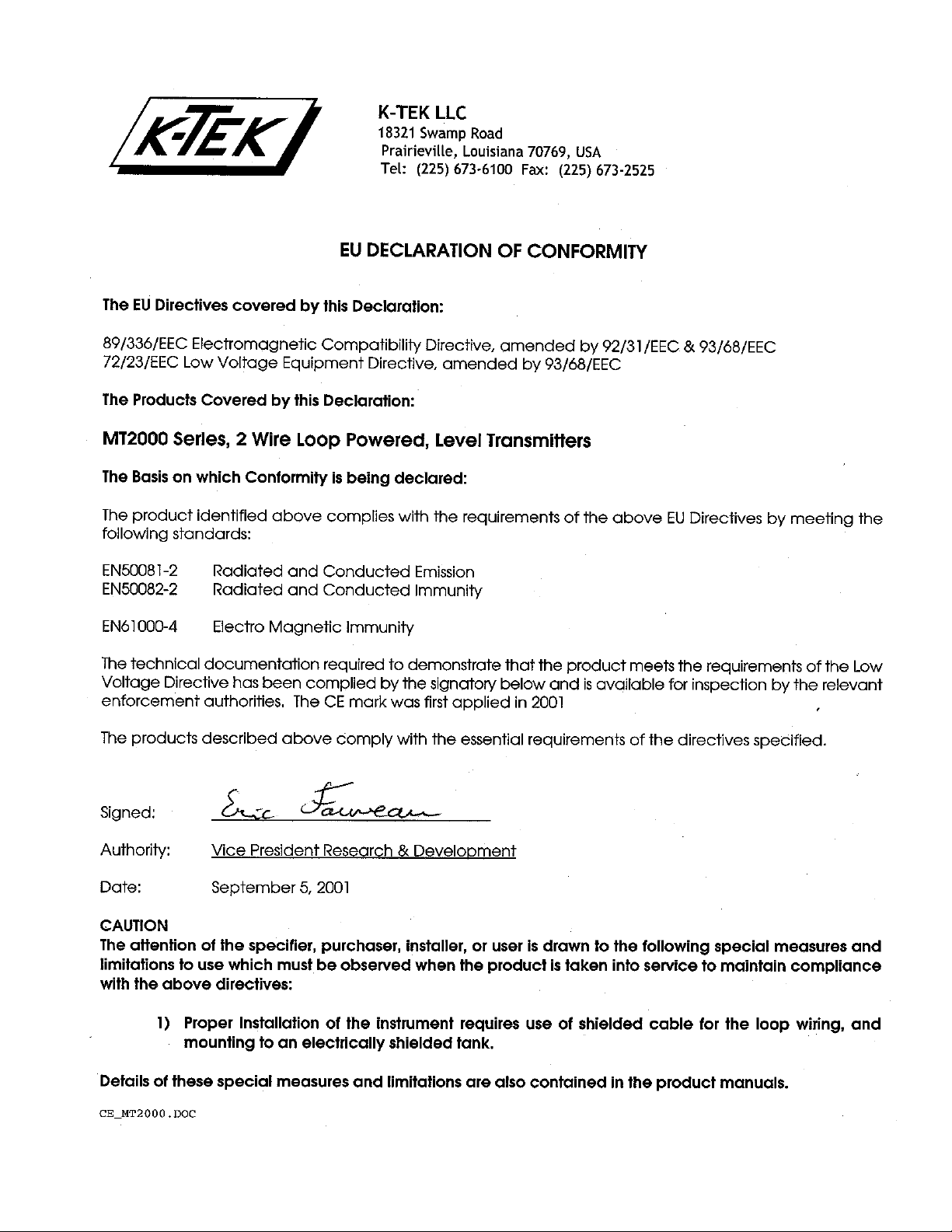
9.6 APPENDIX F: CE Certificate of Conformity
MT2000-0200-1 Rev f (10-2007)
DCN0160 29
Page 30
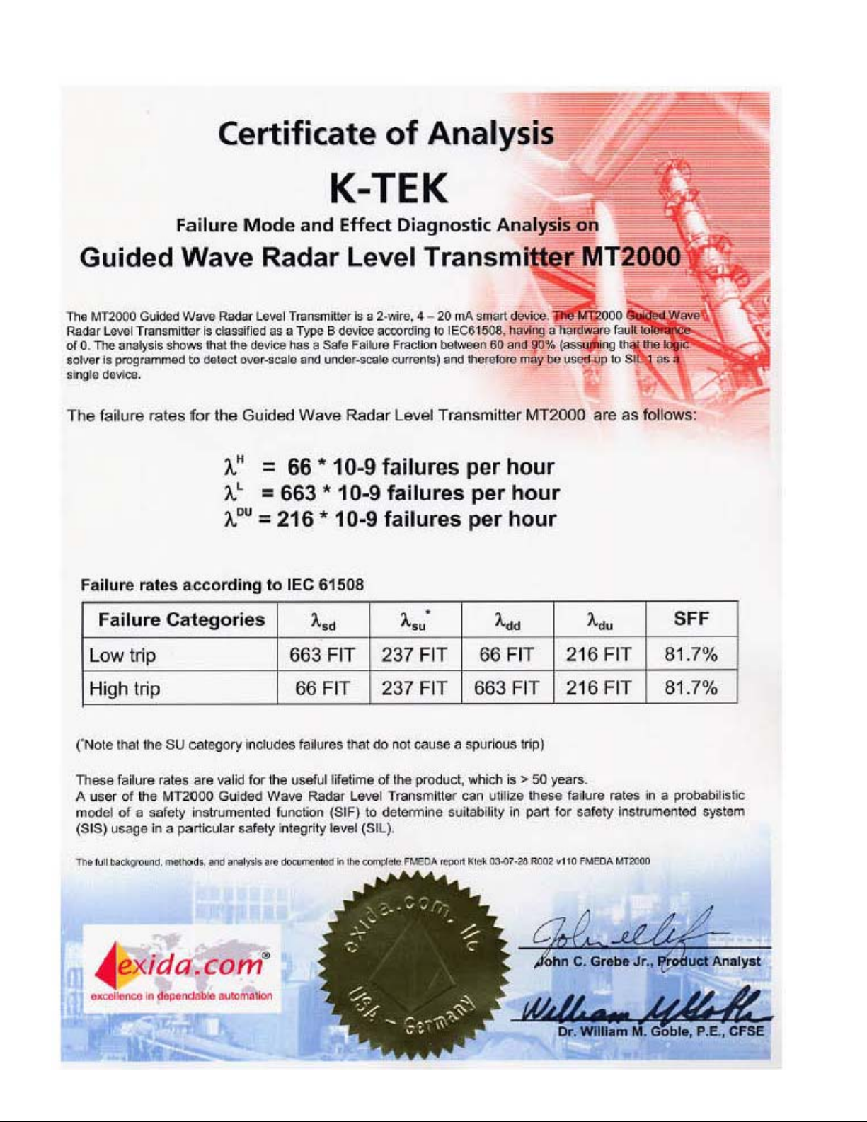
9.7 APPENDIX G: Exida Certificate
30 MT2000-0200-01 Rev f (10-2007)
DCN0160
Page 31
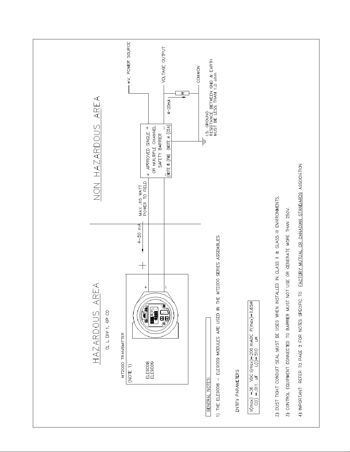
9.8 APPENDIX H: Installation Drawings for Intrinsic Safety & Standard Wiring
MT2000-0200-1 Rev f (10-2007)
DCN0160 31
Page 32

9.8 APPENDIX H: Installation Drawings for Intrinsic Safety & Standard Wiring (continued)
32 MT2000-0200-01 Rev f (10-2007)
DCN0160
Page 33

9.8 APPENDIX H: Installation Drawings for Intrinsic Safety & Standard Wiring (continued)
MT2000-0200-1 Rev f (10-2007)
DCN0160 33
Page 34

9.9 APPENDIX I: Mounting Configurations
Flat Plate
Or
1, 2
Coupling
MINIMUM
DIELECTRIC
CONSTANT
External
MAXIMUM
PROBE
LENGTH
1
1.3
100 ft./30.5 m
4 20 ft./6.1 m
10 40 ft./12.2 m
35 100 ft./30.5 m
Chamber
Nozzle
&
Permanent
Stilling Well
Flange
MINIMUM
DIELECTRIC
CONSTANT
Coaxial
6
Probe
MAXIMUM
PROBE
LENGTH
1
1.3
100 ft./30.5 m
4 20 ft./6.1 m
10 40 ft./12.2 m
35 100 ft./30.5 m
MINIMUM
MAXIMUM
PROBE
LENGTH
1.7 20 ft./6.1 m
3 30 ft./9.1 m
10 50 ft./15.2 m
35 50 ft/15.2 m
7
DIELECTRIC
CONSTANT
Dual Rod
Nozzle &
Flange
MINIMUM
DIELECTRIC
CONSTANT
MAXIMUM
PROBE
LENGTH
1.7 20 ft./6.1 m
3 30 ft./9.1 m
10 50 ft./15.2 m
35 50 ft./15.2 m
MINIMUM
DIELECTRIC
CONSTANT
1.4 20 ft./6.1 m
4 20 ft./6.1 m
10 100 ft./30.5 m
MAXIMUM
PROBE
LENGTH
MINIMUM
DIELECTRIC
CONSTANT
2.5 20 ft./6.1 m
4 20 ft./6.1 m
10 100 ft./30.5 m
MAXIMUM
PROBE
LENGTH
Removable
4 3a, 3b
Stilling Well
MINIMUM
DIELECTRIC
CONSTANT
8
Flat Plate Or
MINIMUM
DIELECTRIC
CONSTANT
MAXIMUM
PROBE
LENGTH
1.7 20 ft./6.1 m
3 30 ft./9.1 m
10 50 ft./15.2 m
35 50 ft/15.2 m
Dual Rod
Coupling
MAXIMUM
PROBE
LENGTH
3 20 ft./6.1 m
4 20 ft./6.1 m
10 100 ft./30.5 m
9, 10a,
10b
1. Accuracy subject to changes in dielectric constant. Ultra-Low Dielectric (ULD) measurement method supports dielectric
constants from 1.3 to a maximum of 2.0.
Figure 9.4
5
34 MT2000-0200-01 Rev f (10-2007)
DCN0160
Page 35

9.10 APPENDIX J: Warranty Statement
5 YEAR WARRANTY FOR:
KM26 Magnetic Liquid Level Gauges; MagWave Dual Chamber System; LS Series Mechanical Level Switches
(LS500, LS550, LS600, LS700, LS800 & LS900); EC External Chambers, STW Stilling Wells and ST95 Seal Pots.
3 YEAR WARRANTY FOR:
KCAP300 & KCAP400 capacitance switches. BETA Pressure and Temperature Switches have a limited factory
guarantee, excluding wetted parts & consumables.
2 YEAR WARRANTY FOR:
AT100, AT100S and AT200 series transmitters; RS80 and RS85 liquid vibrating fork switches; RLT100 and RLT200
reed switch level transmitters; TX, TS, TQ, IX and IM thermal dispersion switches; IR10 and PP10 External Relays;
MT2000, MT5000, MT5100 and MT5200 radar level transmitters; RI100 Repeat Indicators; KP paddle switches;
A02, A75 & A77 RF capacitance level switches and A38 RF capacitance level transmitters; Buoyancy Level
Switches (MS50, MS10, MS8D & MS8F); Magnetic Level Switches (MS30, MS40, MS41, PS35 & PS45).
1 YEAR WARRANTY FOR:
KM50 gauging device; AT500 and AT600 series transmitters; LaserMeter and SureShot series laser transmitters;
LPM200 digital indicator; DPM100 digital indicators; APM100 analog indicators; KVIEW series digital indicators and
controllers; SF50 and SF60 vibrating fork switches, KB Electro-Mechanical Continuous Measuring Devices, KSONIK
ultrasonic level switches, transmitters & transducers, ChuteMaster Microwave Transmitter / Receiver and TiltMaster
Switches.
SPECIAL WARRANTY CONSIDERATIONS:
K-TEK does not honor OEM warranties for items not manufactured by K-TEK (i.e. Palm Pilots). These claims should
be handled directly with the OEM.
K-TEK will repair or replace, at K-TEK’s election, defective items which are returned to K-TEK by the original purchaser within the period specified above from the shipment date of the item and which is found, upon examination
by K-TEK, to its satisfaction, to contain defects in materials or workmanship which arose only under normal use and
service and which were not the result of either alterations, misuse, abuse, improper or inadequate adjustments, applications or servicing of the product. K-TEK’s warranty does not include onsite repair or services. Field ser-
vice rates can be supplied on request.
If a product is believed to be defective, the original purchaser shall notify K-TEK and request a Returned Material
Authorization before returning the material to K-TEK, with transportation prepaid by the purchaser. (To expedite all
returns/repairs from outside of the United States, consult K-TEK’s customer service team (service@ktekcorp.com) to
determine an optimal solution for shipping method and turnaround time.) The product, with repaired or replaced
parts, shall be returned to the purchaser at any point in the world with transportation prepaid by K-TEK for best-way
transportation only. K-TEK is not responsible for expedited shipping charges. If the product is shipped to K-TEK
freight collect, then it will be returned to the customer freight collect.
If inspection by K-TEK does not disclose any defects in material or workmanship, K-TEK’s normal charges for repair
and shipment shall apply (minimum 250.00 USD).
The materials of construction for all K-TEK products are clearly specified and it is the responsibility of the purchaser
to determine the compatibility of the materials for the application.
THE FOREGOING WARRANTY IS K-TEK'S SOLE WARRANTY AND ALL OTHER WARRANTIES EXPRESSED,
IMPLIED, OR STATUTORY, INCLUDING ANY IMPLIED WARRANTY OF MERCHANTABILITY OF FITNESS FOR
A PARTICULAR PURPOSE, ARE EXCLUDED AND NEGATED TO THE MAXIMUM EXTENT PERMITTED BY
LAW. NO PERSON OR REPRESENTATIVE IS AUTHORIZED TO EXTEND ANY OTHER WARRANTY OR CREATE FOR K-TEK ANY OTHER LIABILITY IN CONNECTION WITH THE SALE OF K-TEK’S PRODUCTS. THE
REMEDIES SET FORTH IN THIS WARRANTY ARE EXCLUSIVE OF ALL OTHER REMEDIES AGAINST K-TEK. K
-TEK SHALL NOT BE LIABLE FOR ANY CONSEQUENTIAL, INCIDENTAL, OR SPECIAL DAMAGES OF ANY
KIND. K-TEK’S SOLE OBLIGATION SHALL BE TO REPAIR OR REPLACE PARTS (FOUND TO BE DEFECTIVE
IN MATERIALS OR WORKMANSHIP) WHICH ARE RETURNED BY THE PURCHASER TO K-TEK.
MT2000-0200-1 Rev f (10-2007)
DCN0160 35
 Loading...