

Page 1

Koresound
user Manual
Version 0.1
july 2004
Page 2

Documentation Author
C´edric Gaudin for K-Team S.A.
Ch. de Vuasset, CP 111
1028 Pr´everenges
Switzerland
email: [email protected]
Url: www.k-team.com
Trademark Acknowledgments:
IBM PC: International Business Machine Corp.
Macintosh: Apple Corp.
SUN Sparc-Station: SUN Microsystems Corp.
LabView: National Instruments Corp.
MatLab: MathWorks Corp.
Webots: Cyberbotics
Khepera: K-Team and LAMI
Legal Notice:
• The content of this manual is subject to change without notice.
• All effort have been made to ensure the accuracy of the content of
this manual. However, should any error be detected, please inform
K-Team S.A.
• The above notwithstanding K-Team can assume no responsibility for
any error in this manual.
K-Team S.A. 1
Page 3

Table Of Contents
1 Introduction 3
2 KoreSound Hardware 4
2.1 Overview . . . . . . . . . . . . . . . . . . . . . . . . . . . . . 4
2.2 KoreSound Connections . . . . . . . . . . . . . . . . . . . . . 4
2.2.1 KoreBot Connections . . . . . . . . . . . . . . . . . . 5
2.3 Hardware Protection . . . . . . . . . . . . . . . . . . . . . . . 5
2.3.1 Electrostatic Discharge Protection . . . . . . . . . . . 5
3 KoreSound Software 6
3.1 Overview . . . . . . . . . . . . . . . . . . . . . . . . . . . . . 6
3.2 Linux Sound Driver . . . . . . . . . . . . . . . . . . . . . . . 6
3.3 Basic Commands . . . . . . . . . . . . . . . . . . . . . . . . . 7
3.4 Sound Programming on KoreBot . . . . . . . . . . . . . . . . 7
3.4.1 Sound devices . . . . . . . . . . . . . . . . . . . . . . . 8
3.4.2 Sound device I/O controls . . . . . . . . . . . . . . . . 9
3.4.3 Mixer device I/O controls . . . . . . . . . . . . . . . . 10
K-Team S.A. 2
Page 4

1 Introduction
The KoreSound board is a KoreBot extension that provides audio playback
and recording capabilities.
It offers one audio stereo output and two audio stereo inputs. This
document presents how to use KoreSound.
K-Team S.A. 3
Page 5
2 KoreSound Hardware
2.1 Overview
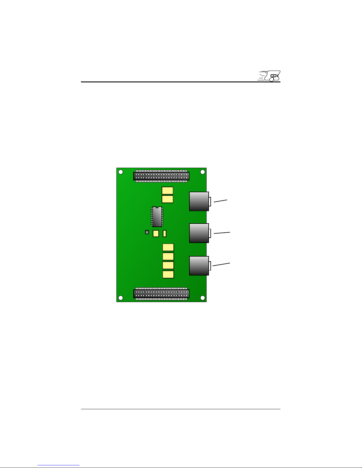
KoreSound can be used in application that requires sound playback and
recording (such as MP3 player, speech synthesis and recognition). The
hardware is quite simple and provides one audio output (OUT) and two
audio inputs (IN1 and IN2).
Figure 2.1 describes the board main components.
IN1
OUT
IN2
Figure 2.1: KoreSound hardware overview
2.2 KoreSound Connections
KoreSound offers three Jack 3.5 mm connectors. The OUT connector is
used as an audio output and standard speaker can be used to hear sound
or music. The IN1 and IN2 connectors are used as two separate audio
inputs and standard microphone or audio source must be plugged in these
connectors to record sound, voice and music.
K-Team S.A. 4
Page 6

2.2.1 KoreBot Connections
The KoreBot connection is pretty straightforward, the boards should be
simply stacked together. The KoreBot will provide the +3.3V power supply
to KoreSound.
2.3 Hardware Protection
2.3.1 Electrostatic Discharge Protection
As any electronic device, the KoreSound may be damaged by Electrostatic
Discharge.
K-Team S.A. 5
Page 7

3 KoreSound Software
3.1 Overview
This chapter presents how to use KoreSound from a KoreBot using the Linux
Operating System. It requires:
• a KoreBot (with a KoreConnect or a KoreSDK)
• a KoreSound
• a terminal emulator software (such as minicom or HyperTerminal)
• a host computer with at least one RS-232 connector (such as a standard
PC running Linux or Windows)
• GNU tools for KoreBot (assembler, linker and C/C++ compiler for
Intel XScale processor) running on your host computer (only for programming sound application)
3.2 Linux Sound Driver
The sound driver for the Linux Operating System is in the standard distribution provided with KoreBot.
The sound driver is normally loaded at startup. You can see all modules
actually loaded with the ’lsmod’ command. In the case the driver is missing,
you can force the loading using the ’modprobe’ command.
Typical output on KoreBot of the ’lsmod’ command:
/bin # lsmod
Module Size Used by
pxa-uda1342-i2c 2504 0 (unused)
soundcore 4072 2 [pxa-uda1342-i2c]
pxa-audio 7456 0 [pxa-uda1342-i2c]
uda1342 2968 0 (unused)
otg243 84832 0 (unused)
Manual sound driver loading:
/bin # modprobe pxa-uda1342-i2c
Using /lib/modules/2.4.19-kb8/kernel/drivers/sound/pxa-audio.o
Using /lib/modules/2.4.19-kb8/kernel/drivers/sound/soundcore.o
Using /lib/modules/2.4.19-kb8/kernel/drivers/sound/pxa-uda1342-i2c.o
PXA25X UDA1342 I2C audio support initialized
K-Team S.A. 6
Page 8

Two devices is created in ’/dev/sound’ by the sound driver:
/bin # ls /dev/sound/*
/dev/sound/dsp /dev/sound/mixer
3.3 Basic Commands
The simplest command that can be used is the standard file copy command
’cp’. This command just copy the content of a source file into a destination file. The idea is to copy a standard wave file (16-bit, stereo) into the
’/dev/dsp’ device. The format of the wave file is very important and it must
be 16-bit audio data with two channels (stereo).
~ # cp test.wav /dev/sound/dsp
The ’madplay’ command can play standard MP3 files.
~ # madplay test.mp3
With the ’cutemixer’ command, you can control the volume, the bass,
the treble as well as the input lines (line1 and line2) level.
Typical output of the ’cutmixer’ command without paramters:
~ # cutemixer
vol(90:90)
bass(0:0)
treble(0:0)
line1(50:50) recordable input-source
line2(0:0) recordable input-source
The vol, bass, treble control the behaviour of the audio output (OUT
connector) and the line1 and line2 correspond to the two audio inputs (IN1
and IN2 connectors).
This example changes the input level of the source connected to IN1.
~ # cutemixer line1 50
line1(50:50) recordable input-source
3.4 Sound Programming on KoreBot
This section shows how to access to the sound driver from your standard
Linux application. The examples given are in standard C and use the standard C library. It requires some knowledge about the file functions on Linux.
K-Team S.A. 7
Page 9

3.4.1 Sound devices
The sound driver creates two devices; /dev/sound/dsp and /dev/sound/mixer.
The first device (’/dev/sound/dsp’) is used to play and record sound. It controls the behaviour of the audio A/D and D/A converters. The mixer device
(’/dev/sound/mixer’) is used to change the input levels and output volumes
in our case.
The two devices are standard files that can be opened using standard C
library ’open’ function.
fd = open( "/dev/sound/dsp" , O_RDWR );
if ( fd < 0 ) {
/* opening failure */
}
...
fd = open( "/dev/sound/mixer" , O_RDWR );
if ( fd < 0 ) {
/* opening failure */
}
To play sound or music, the ’write’ function on device ’/dev/sound/dsp’
must be used.
/* open a wave file to play */
wav_fd = open( "test.wav" , O_RD );
if ( wav_fd < 0 ) {
/* opening error */
}
/* open the sound device */
dsp_fd = open( "/dev/sound/dsp" , O_RDWR );
if ( dsp_fd < 0 ) {
/* opening error */
}
...
while (1)
{
/* read some samples from the wave file */
cnt = read( wav_fd , buf , sizeof(buf) );
if ( cnt == EOF ) break;
/* write the samples into the sound device */
write( dsp_fd , buf , cnt );
}
...
K-Team S.A. 8
Page 10

To record sound or music, the ’read’ function is used.
/* open a wave file to play */
wav_fd = open( "test.wav" , O_RDWR );
if ( wav_fd < 0 ) {
/* opening error */
}
/* open the sound device */
dsp_fd = open( "/dev/sound/dsp" , O_RDWR );
if ( dsp_fd < 0 ) {
/* opening error */
}
...
/*
* select the first input IN1 in setting
* the gain level at maximum value (100%)
*/
mix_fd = open( "/dev/sound/mixer" , O_RDWR );
value = 100;
ioctl( mix_fd , SOUND_MIXER_LINE1 , &value );
close( mix_fd );
...
while (1)
{
/* record some samples from the sound device */
cnt = read( dsp_fd , buf , sizeof(buf));
/* write the samples into the wave file */
write( dsp_fd , buf , cnt );
...
}
...
As you could see in the last example, the input channel is selected by
calling the SOUND MIXER LINE1 I/O control. This I/O control changes
the gain level of the input 1 and selects the input 1 for recording.
3.4.2 Sound device I/O controls
The I/O control are useful to read and to change the settings of the sound
device. Only the sampling rate can be changed.
Supported I/O control commands:
K-Team S.A. 9
Page 11
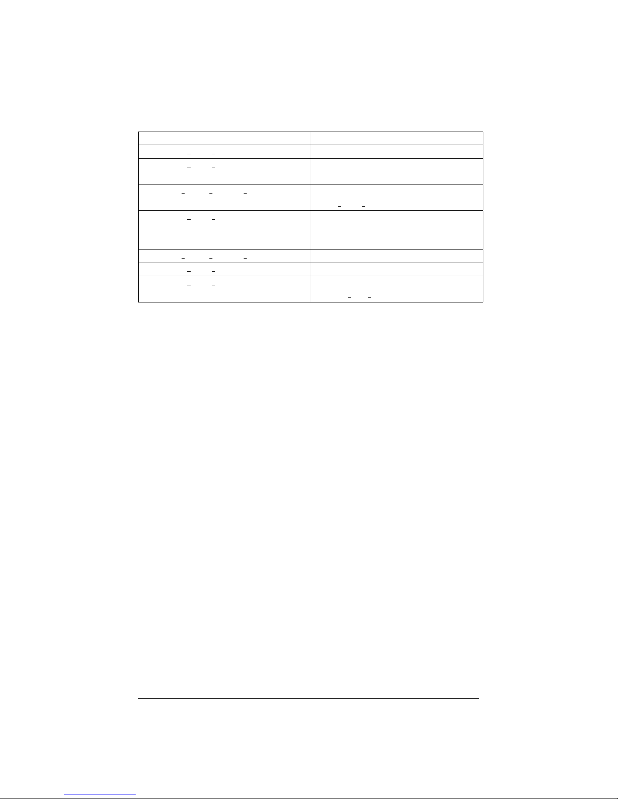
I/O Control Description
SNDCTL DSP STEREO Always reports stereo channel.
SNDCTL DSP CHANNELS Returns the number of channels
used.
SOUND PCM READ CHANNELS Same as SND-
CTL DSP CHANNELS
SNDCTL DSP SPEED Select the sampling rate. 8’000,
16’000, 22’050, 44’100, 48’000 Hz
are supported choices.
SOUND PCM READ RATE Get the sampling rate.
SNDCTL DSP SETFMT Never change the format.
SNDCTL DSP GETFMTS Returns the format. Always returns
AFMT S16 LE.
The two example above shows how to use the ’ioctl’ function to change
or to read sound settings.
...
/* change the sampling rate to 48 kHz */
val = 48000;
ioctl( dsp_fd , SNDCTL_DSP_SPEED , &val );
...
...
/* check if the channels are mono or stereo */
ioctl( dsp_fd , SNDCTL_DSP_CHANNELS , &val );
printf("%s\n", (val==2) ? "stereo" : "mono");
...
3.4.3 Mixer device I/O controls
The I/O control are useful read and changes the settings of the mixer device.
The mixer device is only used for I/O control. It allows to obtain information
about the channels and to change output volume level, bass level, treble level
and inputs level.
Supported I/O control commands:
K-Team S.A. 10
Page 12
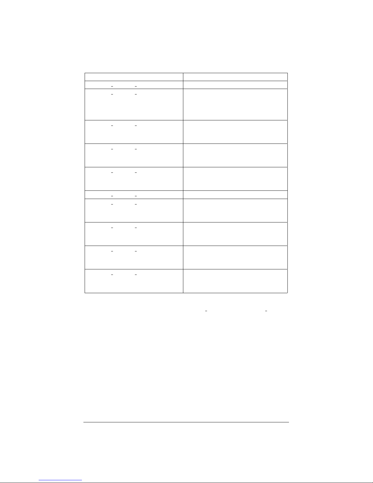
I/O Control Description
SOUND MIXER INFO Fill the structure struct mixer
SOUND MIXER VOLUME Changes the main output volume.
Only the least significant byte is
used to change both left and right
channels.
SOUND MIXER BASS Changes the bass level. Only the
least significant byte is used to
change both left and right channels.
SOUND MIXER TREBLE Changes the treble level. Only
the least significant byte is used to
change both left and right channels.
SOUND MIXER LINE1 Changes the input 1 level. Only
the least significant byte is used to
change both left and right channels.
SOUND MIXER LINE2 Changes the input 2 level.
SOUND MIXER RECSRC Reports the supported recording
sources. Each bit of the mask rep-
resents a recording source.
SOUND MIXER RECMASK Reports the supported recording
channels. Each bit of the mask rep-
resents a recording channel.
SOUND MIXER DEVMASK Reports the supported channels.
Each bit of the mask represents a
channel.
SOUND MIXER STEREODEVS Reports the supported stereo chan-
nels. Each bit of the mask reepre-
sents a stereo channel.
Two examples below show how to set and read a mixer parameter using
’ioctl’ functions for the mixer device. MIXER READ() and MIXER WRITE()
are used to specify if you want to read or to write a mixer setting.
...
/* change the input 1 level to 80% */
level = 80;
ioctl(mixer_fd , MIXER_WRITE( SOUND_MIXER_LINE1 ) , &level );
...
...
/* read the level of the input 1 */
ioctl(mixer_fd , MIXER_READ( SOUND_MIXER_LINE1 ) , &level );
printf("input 1 level %u\n" , level );
...
K-Team S.A. 11
Page 13

K-Team SA
Ch de Vuasset, CP 111
1028 Préverenges
Switzerland
 Loading...