

KTE KT-PPC, KT-PPC-A Instruction Manual
210*297(mm) KTE CO., LTD TI-06(R0)
INSTRUCTION MANUAL
Programmable Power Controller
( GEN : 3 SETS )
KT-PPC
REV
DATE
REASON
MADE
CHECKED
APPROVED
V1.0E
1994.11.
Beginning
D.H.Hwang
S.W.Jeong
J.Y.Chung
V1.1E
2006.11.20.
Change of document form
D.H.Hwang
S.W.Jeong
J.Y.Chung
V1.2E
2007.08.17
Add REMARK
C.Y.Jeong
S.W.Jeong
J.Y.Chung
V1.3E
2008.11.17
Add load balance abnormal function
C.Y.Jeong
S.W.Jeong
J.Y.Chung
V1.4E
2009.02.02.
Add troubles and correcting measures
C.Y.Jeong
S.W.Jeong
J.Y.Chung
V1.5E
2010.01.20.
Add Product Storage Precautions
C.Y.Jeong
S.W.Jeong
J.Y.Chung
V1.6E
2010.07.08.
Changed Operating Temperature follow by ENV Test Report
C.Y.Jeong
S.W.Jeong
J.Y.Chung
Document No.
TIR9402-30-D01

Instruction Manual of
Programmable Power Controller (KT-PPC)
REV
1.6E
PAGE : 2 OF 25
Doc No: TIR9402-30-D01
210*297(mm) KTE CO., LTD TI-06(R0)
TABLE OF CONTENT
1. SPECIFICATIONS........................................................................................................... 3
1.1. APPLICATIONS ................................................................................................................... 3
1.2. GENERAL SPECIFICATIONS .............................................................................................. 4
2. SYSTEM CONSTRUCTION ............................................................................................ 5
2.1. DIAGRAM OF POWER MANAGEMENT CONTROL SYSTEM (FOR SHIP) ........................ 5
2.2. DIAGRAM OF POWER MANAGEMENT CONTROL SYSTEM ............................................ 6
3. SYSTEM FLOW CHARTS .............................................................................................. 7
3.1. Auto Parallel Running by Heavy Load & Pref. Trip ........................................................... 8
3.2. Auto Parallel Running Cancellation by Light Load ........................................................... 9
3.3. Auto Changeover by BUS No Voltage ............................................................................. 10
3.4. Auto Changeover by BUS Abnormal ............................................................................... 11
3.5. Auto Parallel Running by ACB Trip ................................................................................. 12
4. INPUT / OUTPUT SPECIFICATIONS ........................................................................... 13
4.1. TERMINAL INPUT 00 ......................................................................................................... 13
4.2. TERMINAL INPUT 01 ......................................................................................................... 14
4.3. TERMINAL OUTPUT 03 ..................................................................................................... 15
4.4. TERMINAL OUTPUT 04 ..................................................................................................... 16
5. INPUT / OUTPUT REFERENCE TABLES .................................................................... 17
6. INTERNAL SETTING & ADJUSTING ........................................................................... 21
6.1. INTERNAL SETTING TABLE ............................................................................................. 21
6.2. Panel Switch using method ................................................................ .............................. 22
7. DIAGNOSTIC & TROUBLES AND CORRECTING MEASURES ................................. 23
8. EXTERNAL FORM ........................................................................................................ 24
9. PRODUCT STORAGE PRECAUTIONS ....................................................................... 25

Instruction Manual of
Programmable Power Controller (KT-PPC)
REV
1.6E
PAGE : 3 OF 25
Doc No: TIR9402-30-D01
210*297(mm) KTE CO., LTD TI-06(R0)
1. SPECIFICATIONS
1.1. APPLICATIONS
KT-PPC(Programmable Power Controller) optimizes the ship and ground power generation systems
and efficiently perform an active power management & control by controlling KT-ASD(Auto synchronizing
Device) and KT-PWC(Power Controller). Normally KT-PPC is designed to control 3 generators but you
can enlarge its capacity to maximum 5 generators with extension module.
AND self-diagnosis function lets you find out the cause of the errors in the case of problems, so it is
easy for you to maintain the power control system. You can build electric power control system for
various applications by modifying or changing the control program according to your system
configurations.
【 MODEL CLASSIFICATION 】
① KT-PPC (without Big Motor Starting function)
② KT-PPC-A (with Big Motor Starting function)
◈ MAIN FUNCTIONS
• Auto Parallel Running by Heavy Load & Pref. Trip
• Auto Parallel Running Cancellation by Light Load
• Auto Changeover by BUS NO Voltage
• Auto Changeover by BUS Abnormal
• Auto Parallel Running by ACB Trip
• Generator Engine Control ( Start / Stop)
• Big Motor Start Control
• Input / Output LED Display
• Self test & Error Display
• Load Balance Abnormal (RATING POWER X ±5%, DELAY TIME 120SEC.)
Instruction Manual of
Programmable Power Controller (KT-PPC)
REV
1.6E
PAGE : 4 OF 25
Doc No: TIR9402-30-D01
210*297(mm) KTE CO., LTD TI-06(R0)
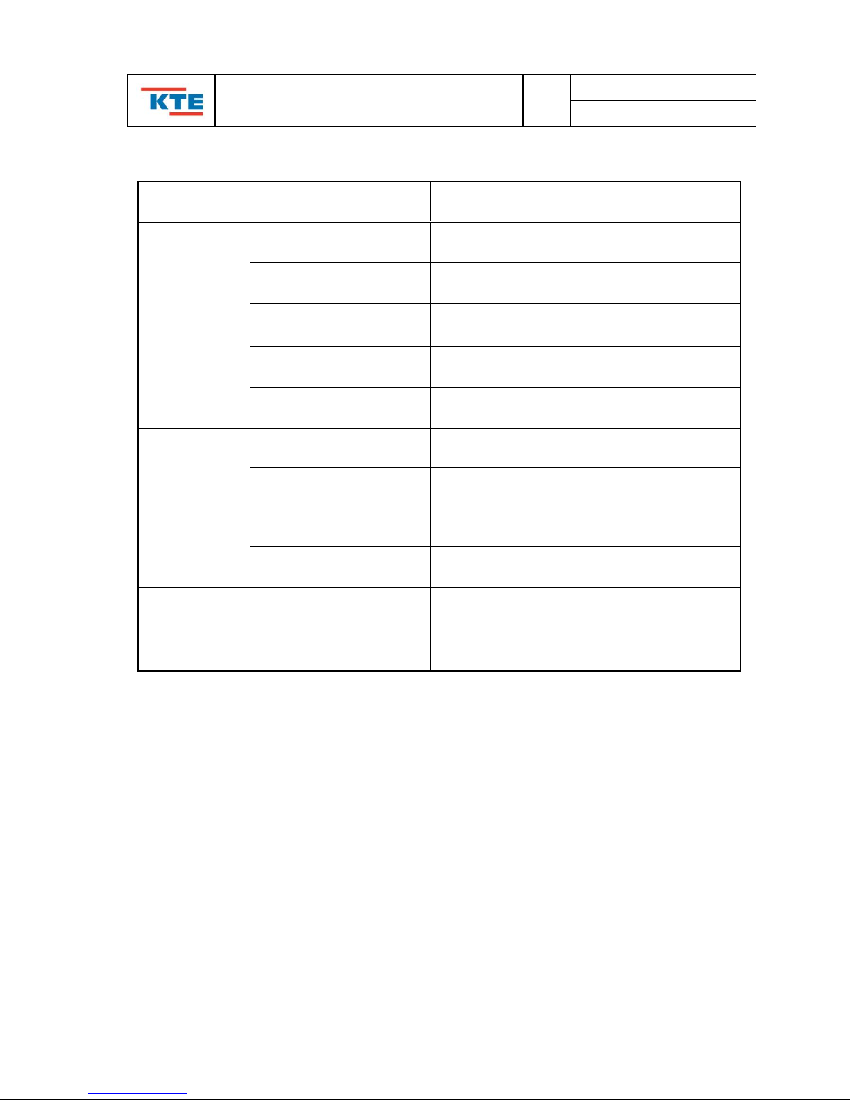
1.2. GENERAL SPECIFICATIONS
Item
Description
General
Specifications
Power Source
DC 24V ±20%
Current Consumption
Max 1A / DC 24V
Temperature range
Operating temp : 0 ~ 55℃
Storing temp : -10℃ ~ 70℃
Weight
Approx. 5Kg
Communication
RS-232c serial 1 port
CPU
Specification
Control system
Intel 80c196kc 16Bit microcomputer
Program system
Assemble description system
Program memory
External 32K bytes(27c256) EPROM
Memory
Internal 256bytes RAM
External 32K bytes(28c256) EEPROM
Input / Output
Specification
Input signal
Digital input : 48 Channel (on/off)
Analog input : 5 Channel (4 ~ 20mA)
Output signal
Contact output : 8 Channel('a" contact)
Signal output : 32 Channel(positive signal)

Instruction Manual of
Programmable Power Controller (KT-PPC)
REV
1.6E
PAGE : 5 OF 25
Doc No: TIR9402-30-D01
210*297(mm) KTE CO., LTD TI-06(R0)
2. SYSTEM CONSTRUCTION
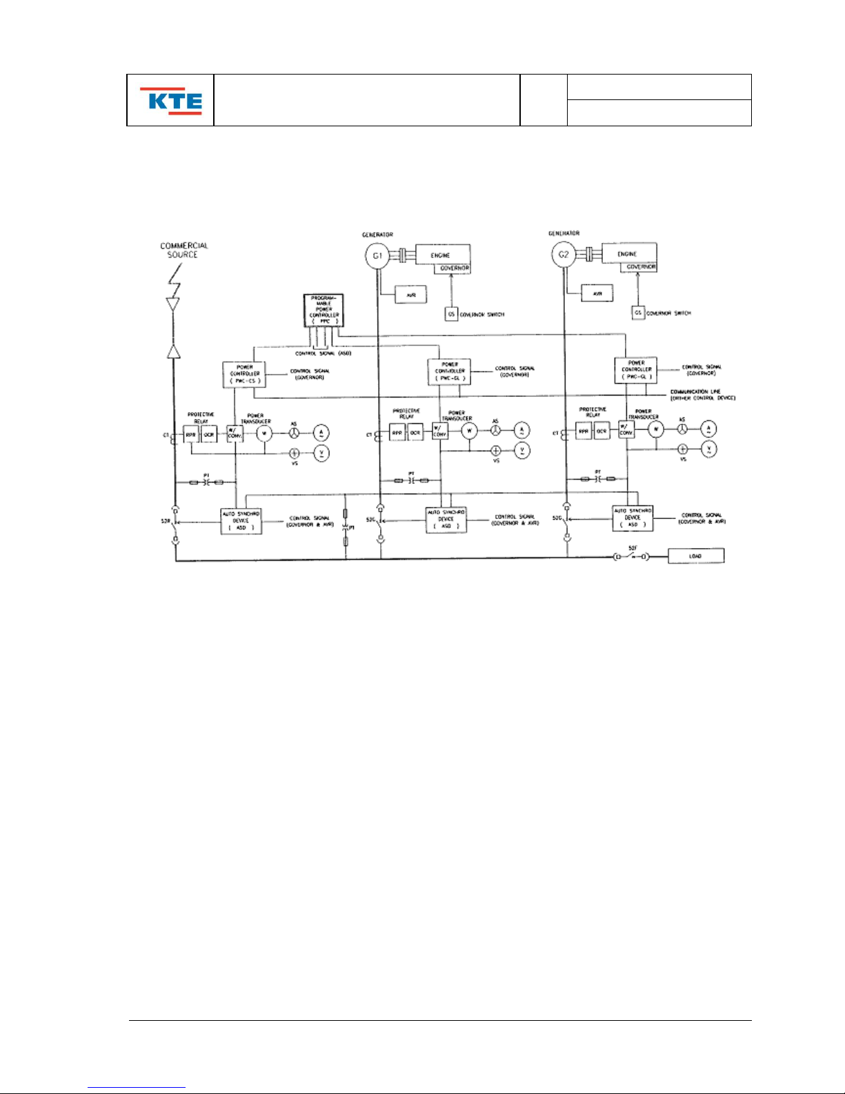
2.1. DIAGRAM OF POWER MANAGEMENT CONTROL SYSTEM (FOR SHIP)
<REMARK>
1. PWC : Generator power controller for ship.
2. Each PWC is used for controlling up to 3 generators
3. PWC can be connected up to max. 5 units by communication line.
Instruction Manual of
Programmable Power Controller (KT-PPC)
REV
1.6E
PAGE : 6 OF 25
Doc No: TIR9402-30-D01
210*297(mm) KTE CO., LTD TI-06(R0)
2.2. DIAGRAM OF POWER MANAGEMENT CONTROL SYSTEM
(WITH INCOMING POWER)
<REMARK>
One unit of PWC used for each generator.
(Maximum of 15 units can be used)

Instruction Manual of
Programmable Power Controller (KT-PPC)
REV
1.6E
PAGE : 7 OF 25
Doc No: TIR9402-30-D01
210*297(mm) KTE CO., LTD TI-06(R0)
3. SYSTEM FLOW CHARTS
3.1. Auto Parallel Running by Heavy Load & Pref. Trip
- Refer to Flowchart
3.2. Auto Parallel Running Cancellation by Light Load
- Refer to Flowchart
3.3. Auto Changeover by BUS No Voltage
- Refer to Flowchart
3.4. Auto Changeover by BUS Abnormal
- Refer to Flowchart
3.5. Auto Parallel Running by ACB Trip
- Refer to Flowchart
Instruction Manual of
Programmable Power Controller (KT-PPC)
REV
1.6E
PAGE : 8 OF 25
Doc No: TIR9402-30-D01
210*297(mm) KTE CO., LTD TI-06(R0)
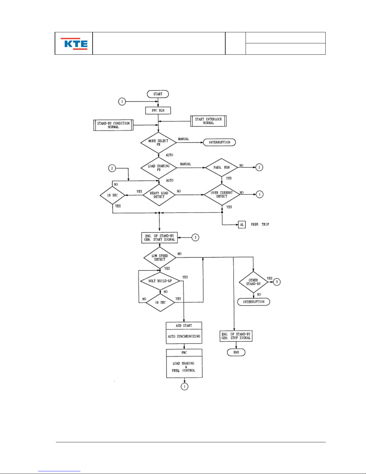
3.1. Auto Parallel Running by Heavy Load & Pref. Trip
 Loading...