

Page 1
M148-ZAK220-001
220X AUTO FOCUS
ZOOM COLOR CAMERA
Operation Manual
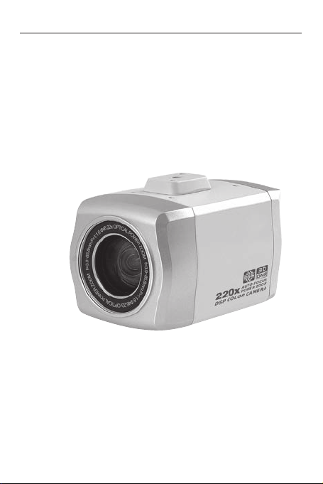
High Resolution WDR - Color Camera
with 22x Optical and 10x Digital - Zoom Lens
Thank you for choosing our high quality camera.
Before attempting to connect or operate, please read and
follow these instructions.
Page 2

Page 3

Cautions
This device complies with Part 15 of the FCC Rules.
Operation is subject to the following two conditions;
1. This device may not cause harmful interference.
2. This device must accept any interference received, including
interference that may cause undesired operation.
Note -
This equipment has been tested and found to comply with the limits for a
Class A digital device, pursuant to part 15 of the FCC Rules. These limits
are designed to provide reasonable protection against harmful interference
when the equipment is operated in a commercial environment. This
equipment generates, uses, and can radiate radio frequency energy and,
if not installed and used in accordance with the instruction manual, may
cause harmful interference to radio communications. Operation of this
equipment in a residential area is likely to cause harmful interference in
which case the user will be required to correct the interference at his own
expense.”
WARNING -
This is a class A product. In a domestic environment this product may
cause radio interference in which case the user may be required to take
adequate measures.
Caution -
Any changes or modications in construction of this devies which are not
expressly approved by the party responsible for compliance could void the
user’s authority to operate the equipment.
1. A regulated DC12V 500mA power supply is recommended for use with this camera
for the best picture and the most stable operation.
An unregulated power supply can cause damage to the camera.
When unregulated power supply is applied, product warranty will be
out of subject.
2. It is recommended that the camera is used with a monitor that has a CCTV quality 75
video impedance level. If your monitor is switched to high impedance then please adjust
accordingly.
3. Do not attempt to disassemble the camera to gain access to the internal componets.
Refer servicing to your dealer.
4. Never face the camera towards the sun or any bright or reective light, which may
cause smear on the picture and possible damage to the CCD.
5. Do not remove the serial sticker for the warranty service.
CAUTION
3
Page 4
Cautions
Correct Disposal of This Product
(Waste Electrical & Electronic Equipment)
(Applicable in the European Union and other European
countries with separate collection systems)
This marking shown on the product or its literature, indicate that
it should not be disposed with other household wastes at the end
of its working life. To prevent possible harm to the environment or
human health from uncontrolled waste disposal, please separate
this from other types of wastes and recycle it responsibly to
promote the sustainable reuse of material resources.
This product should not be mixed with other commercial wastes
purchased this product, or their local government ofce, for details
of where and how they can take item for environmentally safe
recycling.
Business users should contact their supplier and check the terms
and conditions of the purchase contract.
Household users should contact either the retailer where they for
disposal.
CAUTION : TO REDUCE THE RISK OF ELECTRIC SHOCK, DO
RISK OF ELECTRIC SHOCK DO NOT OPEN
NOT REMOVE COVER(OR BACK).
NO USER. SERVICING TO QUALIFED SERVICE PERSONNEL.
This symbol is intended to alert the user to the presence of
uninsulated "dangerous voltage" within the product's enclosure
that may be of sufcient mangnitude to constitute a risk of
electric shock to persons.
This symbol is intended to alert the user to the presence of
important operating and maintenance(servicing) instruction in
the literature accompanying the appliance.
CAUTION
4
Page 5

Contents
···························································
Cautions
1 General
2 Installation
3 Camera setup
···························································
1.1 Product Overview
1.2 Features
1.3 Specications
1.4 Dimensions
1.5 Back panel controls and connectors
2.1 Power
2.2 Video
2.3 Remote Control
3.1 Zoom
3.2 Focus
3.3 OSD setup menu
························································
························································
·························································
2.3.1 RS-485
2.3.2 DC-Lens control
2.3.3 Day- / Night switching
························································
·······················································
3.3.1 OSD display
3.3.2 Menu Structure
3.3.3 Setup - Menu Operation
3.3.3.1 FOCUS
3.3.3.2 EXPOSURE
3.3.3.3 White Balance
3.3.3.4 D-WDR/BLC
3.3.3.5 DAY& NIGHT
3.3.3.6 IMAGE
3.3.3.7 SPECIAL
3.3.4 RESET
··········································
·····················································
···············································
··················································
············································
················································
······································
·······························
···················································
··········································
··········································
·······································
·····························
········································
··································
································
··································
·································
·········································
······································
················································
·····················
10
11
11
12
12
12
13
16
18
18
19
20
22
23
24
26
6
6
6
6
8
9
9
9
10
13
14
3
7
5
Page 6

1 GENERAL
1.1 PRODUCT OVERVIEW
The is a high resolution color camera equipped with a
22x auto-focus zoom lens and 10 x digital zoom.
Many advanced features allow utilizing the in a wide range of
CCTV - applications.
1.2 FEATURES
• 22 x optical and 10 x digital zoom
• 600 TVL horizontal resolution
• 3DNR noise reduction
• Enhanced sensitivity with 256 x DSS(Digital Slow Shutter)
• Extended wide dynamic with D-WDR
• HSBLC : Highlight Suppression BLC
• 8 privacy zones
• Day- / Night mode
• Remote control by RS-485 and DC lens control
1.3 SPECIFICATIONS
Image sensor 1/4” Sony Super HAD CCDⅡ
Effective pixel 752 x 582 (PAL), 768 x494(NTSC)
Light sensitivity 0.2 Lux ( F = 1,6, AGC high, DSS off, 30 IRE)
Lens 22x optical zoom 3.9 ~ 85.8 mm
Video output BNC socket, composite 1 Vs-s / 75 Ohm
Video resolution 600 TV lines horizontal
Signal/noise ratio > 50 dB (AGC off)
Min. object distance 1 cm (wide) up to 1m (tele)
Digital Slow Shutter auto, manual, off (2x to 256x)
Remote control RS-485
Back light compensation HSBLC on/off, BLC on/off
Camera title max. 20 character, 16 colors
Power DC 12V +/- 10%, MAX. 210mA
Environmental temp. -14°F~122°F(-10°C~+50°C)
Humidity Less than 80%
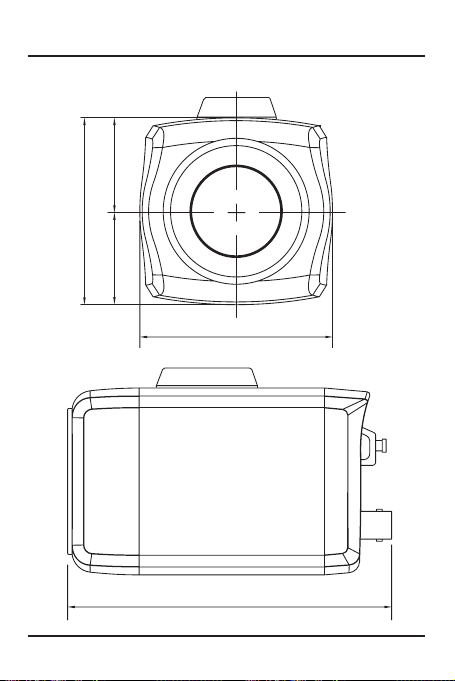
Dimensions (WxHxD) 66 x 64 x 111 mm
Weight Approx. 400g
(Pelco-D/P)
, DC lens control
(+/- 5VDC)
6
Page 7
1 GENERAL
1.4 DIMENSIONS
38.232.0
64.0
66.0
110.8
7
Page 8
1 GENERAL
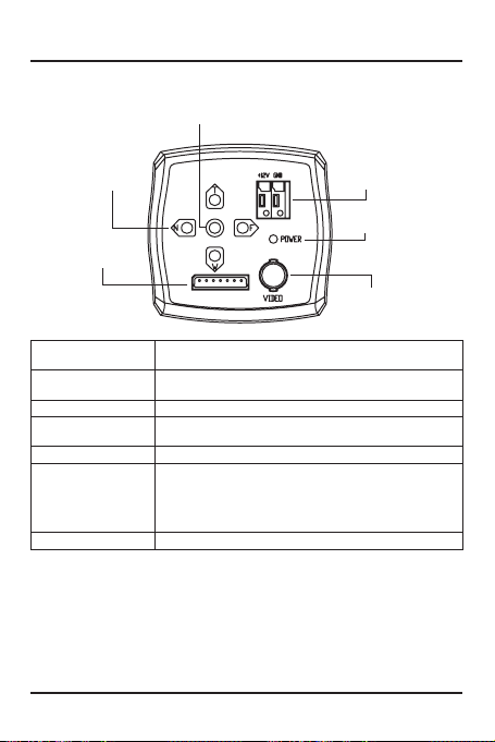
1.5 BACK PANEL CONTROLS AND CONNECTORS
MENU key
Arrow keys
T / W / N / F
12V / GND
LED
Control inputs
D/N
485-
GND
485+
COM
ZOOM
FOCUS
Arrow keys T / W Buttons for zoom control, in OSD menu row
Arrow keys N / F Buttons for focus control, in OSD menu change of
MENU key Open/close OSD setup menu
Video output BNC Video output BNC, composite 1 Vs-s / 75 Ohm
LED LED on indicates power on.
Control inputs 485+ / 485-: Remote control input RS485
12V / GND Power input terminal for 12 VDC stabilized (+/- 10%)
selection up/down
parameters
ZOOM/COM/FOCUS:
input for zoom/focus control with +/- 5VDC
D/N / GND:
contact input for external day/night - switching
8
Video output BNC
Page 9

2 INSTALLATION
2.1 POWER
Connect a stabilized 12 VDC power supply (500mA or higher)
to the power terminal.
2.2 VIDEO
INTERMEDIATE END MONITOR
VIDEO VIDEO
Connect the video output (BNC) with 75 Ohm video coax cable
with DVR, monitor or other equipment with video input. Please
take care for correct 75 Ohm termination.
9
Page 10

2 INSTALLATION
2.3 REMOTE CONTROL
The camera provides an input for RS-485 control with Pelco-D/
P protocol.
Further on the lens can be controlled by control devices with 5
VDC voltage (PTZ-receiver, control keyboards with DC output).
The day / Night mode can be switched by an external contact.
2.3.1 RS-485
Connect the RS-485 input with twisted pair cable to the control
device.
For details of RS-485 wiring please consult the related chapters
in user manuals of DVRs or control keyboards.
The RS-485 parameter (baud rate / address) need to be
adjusted in the OSD menu SPECIAL.
Control commands for OSD - menu (Pelco-D/P protocol)
(Go to) Preset 95 (or Preset 96) OSD setup menu open / close
Joystick/arrow keys up / down or zoom +/- switch between menu lines
Joystick/arrow keys left / right or focus +/- change of values / parameters
Joystick/arrow key right or focus + Enter
10
Page 11

2 INSTALLATION
2.3.3 DC-Lens control
The lens can be controlled by control devices with 5 VDC
voltage (PTZ-receiver, control keyboards with DC output).
Please check the control device to correct output voltage
(+/- 5VDC max).
2.3.3 Day- / Night switching
The day/night switching can be controlled by an external dry
contact. Closing the contact (to GND) will turn the camera in
night mode. In OSD menu DAY&NIGHT the item MODE needs
to be set to EXTERNAL.
ATTENTION: This camera is equipped with a xed IR-cut lter.
For this reason the camera is not applicable for installation with
IR illumination.
11
Page 12

3 CAMERA SETUP
Zoom tele
Focus near Focus far
3.1 ZOOM
The key T is used for zoom in, W for zoom out.
3.2 FOCUS
The key N focuses the lens in near distance, F key focuses in
far distance.
ATTENTION: The FOCUS keys are deactivated in the mode
FOCUS: AUTO
MENU
Zoom wide
12
Page 13

3 CAMERA SETUP
3.3 OSD SETUP MENU
3.3.1 OSD display
NO Function Format Description
Focus
WB
WDR
①
BLC
HSBLC
Night
Freeze
Filp
Auto Focus
Interval AF
Zoom Trigger AF
Manual Focus
ATW
AWB
Push Auto WB
Manual WB
Indoor WB
Outdoor WB
WDR Off
WDR On
BLC Off
BLC On
HSBLC Off
HSBLC On
Day
Night
Normal
Freeze On
Normal
Horizontal Filp
(Mirror)
Vertical Filp
HV(180˚) Fiilp
NO Function Format Description
②
Motion
Zoom
③
Ration
④
ID:000 ~ ID:255 Camera ID
⑤
LOADING... Standby message
⑥
Title
13
Normal
Motion Detected
Optical Zoom
Digital Zoom
Max.20
characters /
Position Selectable
Page 14

3 CAMERA SETUP
3.3.2 Menu Structure
SETUP
1. FOCUS
2. EXPOSURE
3. WHITE BAL ATW
4. D-WDR/BLC OFF
5. DAY&NIGHT AUTO
6. IMAGE
7. SPECIAL
8. RESET OFF
9. EXIT
┛
┛
┛
┛
┛
FOCUS
FOCUS MODE
ZOOM START .|...... 1
ZOOM STOP ….. | 220
ZOOM SPEED FAST
D-ZOOM ON
MIN. DIST 50CM
RETURN
EXPOSURE
SHUTTER OFF
IRIS AUTO
AGC AUTO
MAX. AGC MIDDLE
MAX. FIELD OFF
BRIGHT …….. |…. 50
RETURN
WHITE BAL
D-WDR / BLC
ZOOM TRIG
┛
┛
AF INTERVAL
RUN TIME ..| … 10
INTERVAL ..| …… 60
RETURN
IRIS MANUAL
LEVEL ..|…….. 100
RETURN
AGC MANUAL
LEVEL |……. -3DB
RETURN ┛
WB MANUAL
RED ....|…… 50
BLUE .…|…… 50
RETURN ┛
D-WDR
LEVEL ….|…… 9
RETURN
BLC
LEVEL MIDDLE
AREA ┛
RETURN ┛
HSBLC
LEVEL ….. | ….. 4
AREA
DISP. MODE ALL DAY
RETURN
14
┛
┛
┛
┛
┛
BLC AREA
H. START 2
V. START 2
WIDTH 4
HEIGHT 4
RETURN
HSBLC AREA
H. START 0
V. START 3
WIDTH 8
HEIGHT 4
RETURN
┛
┛
Page 15

3 CAMERA SETUP
DAY & NIGHT
IMAGE
SPECIAL
┛
┛
┛
┛
┛
┛
SMART IR
3DNR
FREEZE OFF
ROTATE OFF
SHARPNESS ..|… 15
NEGATIVE OFF
RETURN ┛
CAM ID 001
BAUDRATE 9600
LANGUAGE ENG
TITLE
PRIVACY
MOTION
OSD SET ┛
RETURN
D&N AUTO
SMART IR
3DNR
TITLE
PRIVACY
MOTION
OSD SET
┛
┛
┛
┛
┛
┛
┛
┛
┛
┛
DETECT MODE VIDEO
DWELL TIME ..|…… 5
BURST ON
RETURN
GAIN ….|.... 8
AREA
RETURN
LEVEL ….. |…. 50
RETURN ┛
----------------------- ABCDEFGHIJKLM (LEFT)
NOPQRSTUVWXYZ (RIGHT)
0123456789► →← (SPACE)
↑↓
( ) -■/=& : ~,. (BACK)
DISPLAY ON
CLEAR OFF
POSITION
RETURN
MASK NO 1
DISP MODE INT.LOCK
AREA
COLOR C0
TRANSPARENT OFF
RETURN
AREA NO 1
DETECT MODE ON
H. START ..|… 31
V. START .|…. 18
WIDTH …|… 53
HEIGHT …|… 37
SENSE …|… 10
DISP. MODE OFF
RETURN
CAM ID OFF
ZOOM MAG OFF
FUNC OSD OFF
OSD COLOR C3
RETURN
15
D&N VIDEO
D->N LEVEL ….|.... 176
D<- N LEVEL ….|.... 76
RETURN
H. START 3
V. START 2
WIDTH 2
HEIGHT 3
RETURN
CURRENT TITLE
RETURN
WIDTH .|…… 10
HEIGHT ..|…… 10
ZOOM POSI ← W T
MASK RESET OFF
RETURN
WIDTH . .|…. 10
HEIGHT ..|…. 10
PAN POSI ∙∙∙∙|∙∙∙∙ 0
TILT POSI ∙∙∙∙|∙∙∙∙ 0
ZOOM POSI ← W T
MASK RESET OFF
RETURN
┛
SMART IR AREA
┛
TITLE POSITION
┛
INT.LOCK MASK
」
NON. LOCK MASK
」
→
→
Page 16

3 CAMERA SETUP
3.3.3 Setup - Menu Operation
MENU
Press the key MENU for opening the OSD setup menu.
The screen shows the main setup menu.
NEAR / FAR
1. FOCUS 」
2. EXPOSURE 」
3. WHITE BAL ATW / AWB / PWB」/ MWB」 / IWB / OWB
4. D-WDR/BLC OFF / D-WDR」 / BLC」 / HSBLC」
5. DAY&NIGHT AUTO」 / COLOR / BW / EXTERNAL
6. IMAGE 」
TELE / WIDE
7. SPECIAL 」
8. RESET OFF / ON」
9. EXIT 」
The keys T / W move the cursor vertical between the rows, changing
parameters and values is done by the FOCUS - keys N / F.
The character
The F key is used for conrming settings (ENTER) and for opening sub-
menus.
In sub-menus the line RETURN is used for exit and return to main menu.
The OSD menu can be closed in any position by MENU key.
Attention: If MENU key is used for exit of a menu page, all changes in
settings are cancelled.
For saving the changes go to the last row
with F (right) - key.
」
indicates a sub-menu.
SETUP
and conrm
16
Page 17

3 CAMERA SETUP
3.3.3.1 FOCUS
FOCUS
FOCUS MODE
ZOOM START
ZOOM STOP
ZOOM SPEED
D-ZOOM
MIN. DIST
RETURN
FOCUS MODE Focus operation mode
AUTO Auto focus permanent on.
INTERVAL The focus will be checked in intervals in the range 3~255 s
ZOOM TRIG The auto focus function is active at each change of zoom
MANUAL Manual focus adjustment.
ZOOM START Start position of zoom lens, adjustable 1~22
ZOOM STOP End position of zoom lens, adjustable 1~220
ZOOM SPEED Zoom speed, adjustable in 4 steps
D-ZOOM Digital zoom on / off
MIN. DIST Minimum object distance, adjustable in range 1cm to
AF RUN TIME see FOCUS MODE: INTERVAL
INTERVAL see FOCUS MODE: INTERVAL
AUTO/INTERVAL」/ZOOM TRIG/MANUAL
...l... 1 ~ 22
...l... 1 ~ 220
SLOW / NORMAL / FAST / V.FAST
OFF / ON
1CM/10CM/50CM/1M/2M/3M/5M/10M/INF
」
(setup in line INTERVAL) for a dened duration (3 ~255s,
setup in line RUN TIME).
position. After focussing the auto focus function is switched
off.
endless (INF)
17
Page 18

3 CAMERA SETUP
3.3.3.2 EXPOSURE
SHUTTER
IRIS
AGC
MAX. AGC
MAX. FIELD
BRIGHT
RETURN
256FLD / ... / 2FLD / AUTO / OFF / FLK / ... / 1 / 100000
AUTO / MANUAL」
AUTO / MANUAL」
OFF / LOW / MIDDLE / HIGH / SUPER
OFF / 2FLD / 4FLD / ... / 256FLD
···l··· 1 ~ 100
」
EXPOSURE
SHUTTER AUTO: Automatic shutter
IRIS AUTO: Automatic lens control
AGC AUTO: Automatic gain control
FLK: Flickerless mode
1:160~1/100.000: Manual shutter speed
2~256FLD: Fixed value for Digital Slow Shutter
MANUAL: Manual lens control (setup in line IRIS LEVEL)
MANUAL: Manual gain control (setup in line AGC LEVEL)
IRIS LEVEL Adjustment of lens level in lens mode MANUAL
AGC LEVEL Gain adjustment in AGC mode MANUAL
MAX AGC Max. gain value of AGC in AGC mode AUTO
MAX FIELD Adjustment of max. value of DSS (Digital Slow Shutter)
2~256FLD (Field)
BRIGHT Adjustment of image brightness
18
Page 19

3 CAMERA SETUP
3.3.3.3 White Balance
MODE
PUSH RED BLUE RETURN 」
WHITE BAL
ATW
MODE Operation mode of white balance
ATW: Automatic White Balance in temperature range
2400°K to 12000°K
AWB: Temperature range is broader than ATW.
INDOOR: Preset setting for indoor applications
OUTDOOR: Preset setting for outdoor applications
PUSH: One-time, manual started white adjustment, start in
line PUSH
MANUAL: Manual white balance
PUSH ON: Start of white adjustment in mode PUSH
RED In WB - mode "MANUAL" adjustment of RED - level
BLUE In WB - mode "MANUAL" adjustment of BLUE - level
19
Page 20

3 CAMERA SETUP
3.3.3.4 D-WDR/BLC
MODE D-WDR
LEVEL ···l··· 9
AREA DISP. MODE RETURN 」
D-WDR / BLC
Mode: D-WDR Digital Wide Dynamic Range for balancing strong light
differences in scenery
Level Adjustment of WDR level
D-WDR / BLC
MODE BLC
LEVEL MIDDLE
AREA 」
DISP. MODE RETURN 」
BLC AREA
H. START 3
V. START 2
WIDTH 2
HEIGHT 3
RETURN 」
Mode: BLC Back Light Compensation, dark objects enclosed with
backlight will be brightened.
Level Compensation level in 3 steps
Area Adjustment of area for BLC
H.START: Position of 1. eld of area from left (0~7)
V.START: Position of 1. eld of area from top (0~7)
WIDTH: horizontal size of the area in elds (0~8)
HEIGHT: vertical size of the area in elds (0~8)
20
Page 21

3 CAMERA SETUP
MODE HSBLC
LEVEL ···l··· 4
AREA 」
DISP. MODE ALL DAY
RETURN 」
D-WDR / BLC
Mode: HSBLC Highlight suppression, strong light sources (e.g. car lamps)
will be blacked out in image
Level Sensitivity trigger level in 9 steps
Area Adjustment of monitored area for HSBLC in a grid 8x8
DISP.MODE ALL DAY: HSBLC is always on
H.START: Position of 1. eld of area from left (0~7)
V.START: Position of 1. eld of area from top (0~7)
WIDTH: horizontal size of the area in elds (0~8)
HEIGHT: vertical size of the area in elds (0~8)
NIGHT: HSBLC only active in night mode
21
Page 22

3 CAMERA SETUP
3.3.3.5 DAY& NIGHT
MODE AUTO
DETECT MODE VIDEO
DWELL TIME ···l······ 5
D>N LEVEL ······l··· 176
D<N LEVEL ····l····· 76
BURST ON
RETURN 」
D&N AUTO
MODE AUTO: Automatic day/night switching
DETECT MODE VIDEO: In mode AUTO the D/N switching is controlled by
COLOR: day / color mode
BW: night / b/w mode
EXTERNAL: Switching by external contact
video signal level
SENSOR: not supported mode
DWELL TIME Delay time for switching 0~60 s
D>N LEVEL Sensitivity trigger level for switching day to night, range
D<N LEVEL Sensitivity trigger level for switching night to day, range
BURST ON: color burst in video signal also in b/w mode
ATTENTION:
reason the camera is not applicable for installations with IR illumination.
1~255
0~254
OFF: color burst in video signal in b/w mode off
This camera is equipped with a xed IR-cut lter. For this
22
Page 23

3 CAMERA SETUP
3.3.3.6 IMAGE
IMAGE
SMART IR 」
3 DNR 」
FREEZE OFF
ROTATE OFF
SHARPNESS ······l··· 15
NEGATIVE OFF
RETURN 」
SMART IR Mode not supported
3DNR Digital Noise Reduction
FREEZE ON: Freeze of current image
ROTATE ON: Image turn 180°
SHARPNESS Adjustment of image sharpness, range 0~31
NEGATIVE ON: Negation of image colors
MODE: ON : Noise reduction deactivated
LEVEL: Level adjustment for noise reduction, range 0~100
23
Page 24

3 CAMERA SETUP
3.3.3.7 SPECIAL
SPECIAL
CAM ID 001
BAUDRATE 9600
LANGUAGE ENG
TITLE 」
PRIVACY 」
MOTION 」
OSD SET 」
RETURN 」
CAM ID RS-485 address of camera, range 0~255
BAUDRATE Baud rate of RS-485 transmission, 2400, 4800, 9600, 19200
LANGUAGE OSD menu language, English
TITLE Camera title with max. 20 characters.
or 38400.
Control commands for OSD - menu (Pelco-D/P protocol).
(Go to) Preset 95 (or Preset 96) OSD setup menu open / close
Joystick / arrow keys up /
down or zoom +/Joystick / arrow keys left /
right or focus +/Joystick / arrow key right or
focus +
Characters A~. : Select up to 20 characters for the title,
conrm with MENU key.
DISPLAY: ON: Displays the title.
CLEAR: ON: Deletes the complete title.
POSITION: Adjustment of title position on the screen
by arrow keys.
------------------------------
ABCDEFGHIJKLM (LEFT)
NOPQRSTUVWXYZ (RIGHT)
0123456789► →← (SPACE)
↑↓ ( ) -■/=& : ~,. (BACK)
DISPLAY ON
CLEAR OFF
POSITION ┛
RETURN ┛
24
24
switch between menu lines
change of values /
parameters
Enter
TITLE
Page 25

3 CAMERA SETUP
PRIVACY Privacy zone adjustment, up to 8 areas can be masked.
MOTION Motion detection with up to 4 zones
PRIVACY
MASK NO 1
DISP MODE
AREA
COLOR C0
TRANSPARENT OFF
RETURN 」
INT.LOCK
」
MASK NO: Selection privacy zone 1~8 for setup.
DISP MODE: OFF: Privacy zone not active.
NON.LOCK / INT.LOCK: Privacy zone active.
AREA: WIDTH: Width of privacy zone.
HEIGHT: Height of privacy zone.
PAN POSI: Position horizontal.
TILT POSI: Position vertical.
ZOOM POSI: Setup zoom position / test.
MASK RESET: Removing of mask.
MODE: ON: Motion detection on (zone1~4).
AREA NO: Selection zone 1~4 for setup.
DETECT MODE: ON: Detection active for selected zone.
H.START: Left border of zone.
V.START: Top border of zone.
WIDTH: Width of zone.
HEIGHT: Height of zone.
SENSE: Sensitivity of detection.
DISP.MODE: OSD: In case of detection the symbol
shown on screen.
AREA: In case of detection the area is
shown transparent on screen.
OSD+AREA: In case of detection the symbol
and area are shown on screen.
MOTION
AREA NO 1 ~ 4
DETECT MODE OFF / ON
H. START ··l··· 0 ~ 200
V. START ··l··· 0 ~ 140
WIDTH ··l··· 0 ~ 200
HEIGHT ··l··· 0 ~ 140
SENSE ··l··· 0 ~ 40
DISP. MODE OFF/OSD/AREA
/OSD +AREA
RETURN 」
25
25
is
Page 26

3 CAMERA SETUP
OSD SET Display options
OSD SET
CAM ID OFF
ZOOM MAG OFF
FUNC OSD OFF
OSD COLOR C3
RETURN 」
CAM ID: The RS-485 address will be displayed.
ZOOM MAG: In case of lens operation the zoom
position appears for 5 s.
FUNC OSD: In case of lens operation the status
icons appear for 5 s.
OSD COLOR: Color setup for OSD menu.
3.3.4 RESET
All settings of the camera will be initialized and set to factory defaults.
26
26
Page 27

Page 28

 Loading...