

Page 1
M062-VDW101-002
HIGH RESOLUTION
WD R
ARMORED DOME CAMERA
Th an k yo u fo r ch oo si ng o ur h ig h qu al it y ca me ra .
Be fo re a tt em pt in g to c on ne ct o r op er at e, p le as e re ad a nd f ol lo w
th es e in st ru ct io ns .
OPER ATI O N M ANUAL
Page 2

CO NT EN TS
1. C autions
2. F eatures
3. P ackage
4. O verview and fun ction
5. I nstalla tion
6. C onnecti on
7. D imensio ns
8. S pecific ations
9. O SD Menu
• ME NU D ES CR IP TI ON
• GE NE RA L ST RU CT UR E
• OS D FU NC TI ON DE SC RI PT IO N
- L EN S
- E XP OS UR E
- W HI TE B AL AN CE
- W DR
- D AY & N IG HT
- I MA GE
- S PE CI AL
- CA M TI TL E
- LA NG UA GE
- SY NC
- CO MM A DJ
- PR IV AC Y
- MO TI ON D ET
- DI SP LA Y
• FA CT OR Y DE FA UL T
• EX IT
10.C ommunic ation Pr otocol
2
Page 3

1. Ca ut io ns
This device complies with Part 15 of the FCC
Rules. Operation is subject to the following two
conditions;
1. Th is d ev ic e ma y no t ca us e ha rm fu l in te rf er en ce .
2. Th is d ev ic e mu st a cc ep t an y in te rf er en ce r ec ei ve d, i nc lu di ng
in te rf er en ce t ha t ma y ca us e un de si re d op er at io n.
Note -
Caution -
This equipment has been tested and found to comply with limits for a Class B digital
device, pursuant to part 15 of the FCC Rules. These limits are designed to provide
reasonable protection against harmful interference in a residential installation.
This equipment generates, uses, and can radiate radio communications.
However, there is no guarantee that interference will not occur in a particular
installation. If this equipment off and on, the user is encouraged to try to correct the
interference by one or more of the following measures:
• Reorient or relocate the receiving antenna.
• Increase the separation between the equipment and receiver.
• Connect the equipment into an outlet on a circuit different from that to
which the receiver is connected.
• Consult the dealer or an experienced radio / tv technician for help.
Any changes or modications in construction of this device
which are not expressly approved by the party responsible
for compliance could void the user's authority to operate the
equipment.
1. A regulated DC12V 1.5A power supply is recommended for use with this camera
for the best picture and the most stable operation.
An unregulated power supply can cause damage to the camera.
When unregulated power supply is applied, product warranty will be
out of subject.
2. It is recommended that the camera is used with a monitor that has a CCTV quality
75 video impedance level.
If your monitor is switched to high impedance then please adjust accordingly.
3. Do not attempt to disassemble the camera to gain access to the internal
components. Refer servicing to your dealer.
4. Never face the camera towards the sun or any bright or reective light, which may
cause smear on the picture and possible damage to the CCD.
5. Do not remove the serial sticker for the warranty service.
3
Page 4
1. Ca ut io ns
Correct Disposal of This Product
(Waste Electrical & Electronic Equipment)
(Applicable in the European Union and other European countries with
separate collection systems)
This marking shown on the product or its literature, indicate that it should not
be disposed with other household wastes at the end of its working life. To
prevent possible harm to the environment or human health from uncontrolled
waste disposal, please separate this from other types of wastes and recycle it
responsibly to promote the sustainable reuse of material resources.
This product should not be mixed with other commercial wastes purchased this
product, or their local government ofce, for details of where and how they can
take item for environmentally safe recycling.
Business users should contact their supplier and check the terms and
conditions of the purchase contract.
Household users should contact either the retailer where they for disposal.
4
Page 5

1
CAUTIONS
2. Fe at ur es
• Sony Vertical double-density interline CCD image sensor
• 550TV Lines
• WDR (Wide Dynamic Range), OSD Function
• Digital slow shutter, Manual shutter
• Privacy Zone
• Motion Detection
• IR LED : 30ea, Max 30M
• Manual Pan & Tilt Control for easy installation
- Horizontal 360˚, Pan 360˚, Tilt 140˚
Minute Angle Control ±10˚
• Vandalproof
OPTION
• AC24V / DC12V Dual Voltage
• Fan(standard type)
Ho w WD R ma ke s be tt er i ma ge ?
WD R al lo ws e ve ry d et ai l to b e ca pt ur ed a cc ur at el y ev en i f on e
po rt io n is b ri gh t wh il e ot he r po rt io ns a re d ar k.
(T he d if fe re nc e of t wo p or ti on s co ul d be m or e th an 6 4 ti me )
5
Page 6
2. Fe at ur es
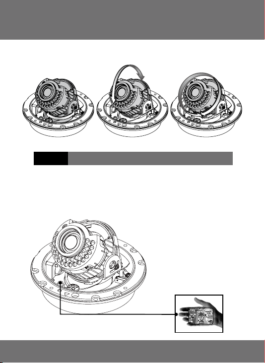
• 3-Axis Gimbal
Pan Rotation Horizontal RotationTilt Rotation
CAU TION pan nin g the brack et in exc ess o f 3 ro tation s in one di rectio n may
caus e dam age to th e cab le.
• Service Video connector
Th e Se rvi ce Vi d eo C on ne c tor al so pr o v id es th e in s ta ll e r wi th an
ea sy w ay o f co nf ig ur in g th e ca me ra .
6
Page 7
2
1
FEATURES
CAUTIONS
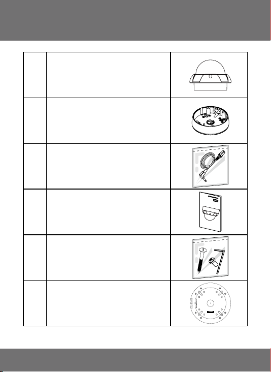
3.
Pa ck ag e
1 ARMORED DOME CAMERA
2 SURFACE MOUNT
3 VIDEO OUTPUT TEST CABLE
4 OPERATION MANUAL
SCREW(M4x10) - 4ea
SCREW(5x30) - 4ea
5
SCREW(M4x40.SUS) - 4ea
L WRENCH - T20
6 MOUNT GUIDE
7
Page 8
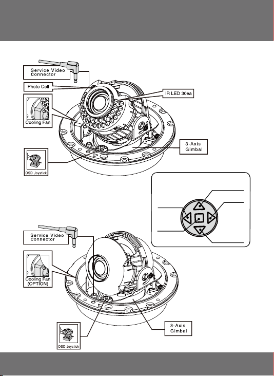
4. Ov er vi ew a nd f un ct io n
• Name (Led Type)
• CONTROL FUNCTION
(OSD JOYSTICK)
LE FT
• Name (Standard)
ME NU
UP
RI GHT
DO WN
8
Page 9
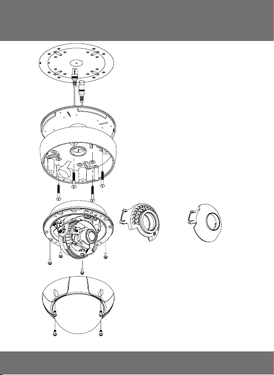
5. I ns ta ll at io n
Mount Guide
Standard TypeLED Type
9
Page 10
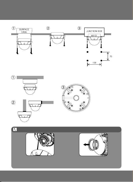
5. I ns ta ll at io n
1. Installation of Flush Mount
①
Installation of the camera with SURFACE
CASE(using M4x40)
②
Installation of the camera with SCREWS
③
Installation of the camera with JUNCTION BOX
2. Installation of Surface Mount
PIPE
PIPE
①
Installation of the camera on the wall
②
Installation of the camera on the 3/4” NPT PIPE
③
Installation of the camera on the JUNCTION BOX
NO T E
Check t he saf e wire which
should be ent irely i nserted into camera
housing durin g locki ng the dome c over to
maintai n Weat herproo f condi tion.
When us ing th e camer a
without LEDs take of f the r ubber.
10
Page 11

6. Co nn ec ti on
• DUAL(DC12V/AC24V)
• DC12V
When you install the camera, please glue up the end of cable to
keep it stable in order to protect the camera from the humidity problems.
11
Page 12

7. Di me ns io ns
Unit : mm
Surface Mount Type
Type A
Flush Mount Type
˚
70
Standard Type LED Type
When you x the focus around 22.0mm in f9.0-22.0mm Varifocal lens, please
set short distance focus approximately 3M and do not set long distance focus.
Type B
˚
45
12
Page 13

8. Sp ec if ic at io ns
Signal Format NTSC PAL
Image Device Sony Vertical double-density interline CCD image sensor
Scanning System 2:1 Interlace
H.Resolution 550TV Lines
Scanning Frequency H:15.734KHz, V:59.94Hz H:15.625KHz, V:50Hz
Total Pixels 811(H) x 508(V) 795(H) x 596(V)
Effective Pixels 768(H) x 494(V) 752(H) x 582(V)
Electronic Shutter 1/60 sec 1/50 sec
Digital Slow Shutter 1 ~ 500 Field
WDR Off / On / AUTO(Level Adjustment)
BLC Off / Bottom / Left / Right / Top / Center
AGC LOW / MID / HIGH
Motion Detection Zone(Whole, Top, Bottom, Center, Left, Right) / Level Adjustable
Privacy Masking Zone 8ea (Mask Off / On)
White Balance ATW / PUSH / PUSH LOOK / USER(R Gain, B Gain)
OSD Built-In
Language English / Chinese / Russian / Spanish / German
S/N Ratio More than 48dB(AGC Off)
Gamma r=0.45
Min. Illumination
Sync System Internal
Video Output 1.0 Vp-p Composite 75(Ω) unbalanced
Po we r
Co ns ump tio n
Operating Temperature -10℃ ~ +50
Storage Temperature -20℃ ~ +60
Operating Humidity 10% ~ 80%
Options Dual Power
Weight
IP Rating
DC12V DC 12V ±10%, Less than 210mA
Dual
• Surface Mount Type A : Approx. 1.38kg / Type B : Approx. 1.1kg
LE D T YP E
Power
Consumption
Min. Illumination 0 Lux (IR LED ON)
IR LED 30ea
IR LED Half Angle ±22 Degree
IR LED Wavelength 850nm
IR Beam Range Up to 30 Meters
IR LED Operation On : 1 Lux or less, Off : 3 Lux more than
DC12V DC 12V ±10%, Less than 550 mA
Dual
1.0 Lux / 30 IRE F2.0
0.001 Lux(DSS)
• DC 12V ±10%, Less than 300mA
• AC 24V ±10%, Less than 3.1W
• Flush type : Approx. 730g
• DC 12V ±10%, Less than 700 mA
• AC 24V ±10%, Less than 6.8W
℃
℃
IP 66 (Weatherproof)
13
Page 14

9. OS D Me nu
MENU DESCRIPTION
• The best clear image can be obtained color camera with
WDR(Wide Dynamic Range).
• The camera switches lenses automatically depending on the
illumination, which promotes the best possible color images during
the day and black / white image at night.
• The camera function can be controlled by OSD menu.
OSD STRUCTURE
▲, ▼ :
•
Me nu u p / do wn
,▶ :
•
Me nu l ef t / ri gh t
◀
:
•
ME NU
■
14 15
Page 15

9. OS D Me nu
GENERAL STRUCTURE
SETUP
>LENS [
EXPOSURE [
WHITE BALANCE [┛]
WDR [
DAY&NIGHT [
IMAGE [
SPECIAL [
FACTORY DEFAULT
EXIT
┛
]
┛
]
┛
]
┛
]
┛
]
┛
]
LENS
>LENS TYPE
LEVEL
INITIAL
RETURN
EXPOSURE
>SHUTTER
FLICKERLESS
AGC
DSS
INITIAL
RETURN
WHITE BALANCE
>WB MODE
RED CONT
BLUE CONT
PUSH CONT
INITIAL
RETURN
WDR
...
DC
...
08
...
1/60
...
OFF
...
MID
...
10x
...
ATW
...
----
...
----
...
----
>WDR MODE
WDR LEVEL
BLC
BLC ZONE
BLC LEVEL
INITIAL
RETURN
...
...
...
...
...
OFF
08
OFF
CENTER
04
Page 16

9. OS D Me nu
DAY & NIGHT
IMAGE
SPECIAL
...
COLOR
...
----
...
----
...
NORMAL
...
10
...
OFF
..
1,00x
...
001
...
ENG
...
ZNT
...
[┛]
...
[┛]
...
[┛]
...
[┛]
>D&N MODE
LEVEL
DWELL TIME
INITIAL
RETURN
>REVERSE
SHARPNESS
FREEZE
D-ZOOM
INITIAL
RETURN
>CAM TITLE
LANGUAGE
SYNC
COMM ADJ
PRIVAC
MOTION DETECT
DISPLAY
INITIAL
RETURN
CAM TITLE
0123456789ABCDEFGHIJKLMN
OPQRSTUVWXYZ!?*#$%()<>{}
SPACE
>> <<BACK
CAMM ADJ
PRIVACY
MOTION DET
...
[┛]
...
000
...
9600
...
...
...
LOCATION
RETURN
>CAM ID
BAUDRATE
INITIAL
RETURN
>ZONE
MASK
POSTION
INITIAL
RETURN
0
OFF
[┛]
CAM TITLE
>LOCATION
WIDTH/HIGHT
RETURN
...
[+]
...
[+]
DISPLAY
...
...
...
...
...
...
OFF
WHOLE
03
OFF
OFF
OFF
>MOTION MODE
ZONE
LEVEL
INITIAL
RETURN
>CAM ID
CAM TITLE
MOTION
INITIAL
RETURN
16 17
Page 17

9. OS D Me nu
LENS MENU STRUCTURE
EXPOSURE MENU STRUCTURE
Page 18

9. OS D Me nu
WHITE BALANCE MENU STRUCTURE
WDR MENU STRUCTURE
18 19
Page 19

9. OS D Me nu
DAY & NIGHT MENU STRUCTURE
IMAGE MENU STRUCTURE
Page 20

9. OS D Me nu
SPECIAL-CAM TITLE
SPECIAL-LANGUAGE
20 21
Page 21

9. OS D Me nu
SPECIAL-SYNC
SPECIAL-COMM ADJ
Page 22

9. OS D Me nu
SPECIAL-PRIVACY
SPECIAL-MOTION DET
22 23
Page 23

9. OS D Me nu
SPECIAL-DISPLAY
Page 24

9. OS D Me nu
OSD FUNCTION DESCRIPTION
1.LENS
: Enable user to select the lens type according to equipped with camera.
Set up using LEFT, RIGHT KEY at each menu.
- LENS TYPE
①ELC : Enable user to set up for BOARD lens.
②DC : Enable user to set up for DC Iris lens.
③VIDEO : Enable user to set up for VIDEO
Iris lens.
- LEVEL
: Enable user to select the level for Brightness
of image(0~15).
- INITIAL
: Enable user to initialize the LENS menu set up.
2. EXPOSURE
: Enable user to set up the function of SHUTTER, FLICKERLESS, AGC, DSS.
Set up using LEFT, RIGHT KEY at each menu.
- SHUTTER
: Enable user to set up the Shutter Speed
-> 1/60(50), 1/100(120), 1/250, 1/500, 1/1K,
1/2K, 1/4K, 1/10K, 1/100K
*() is for PAL TYPE
- FLICKERLESS
: Enable user to set up the FLICKERLESS
ON/OFF.
- AGC
: Enable user to make image bright to amplify
the Gain.
- DSS(Digital Slow Shutter)
: Enable user to enhance video quality in extreme low-light condition to slow down
the shutter speed and collect over multiple elds based on the shutter limit setting.
-> 1X, 5X, 10X, 20X, 40X, 80X, 160X, 320X, 500X
- INITIAL
: Enable user to initialize the Exposure menu set up.
-> LOW, MID, HIGH
24 25
Page 25

9. OS D Me nu
3. WHITE BALANCE
: Enable user to represent the accurate white color by controlling the R,G,B level.
Setting up LEFT, RIGHT KEY on each menu.
- WB MODE
Enable user to trace the White Balance
①
ATW :
automatically in the range of 2,500K~11,000K.
Enable user to search for White Balance
②
PUSH :
automatically. In this mode, color temperature
range is broader than ATW.
③
PUSH LOCK :
Balance according to the color temperature in
the certain environment.
④
USER :
- RED CONT :
In the USER setting of WB MODE, enable user to set the RED GAIN.
- BLUE CONT :
In the USER setting of WB MODE, enable user to set the BLUE GAIN.
- PUSH AUTO :
In the PUSH LOCK setting of WB MODE, enable user to x the White Balance in
camera setting.
Enable user to reset the WHITE BALANCE menu setting.
- INITIAL :
4. WDR
: Use the condition which Image doesn’t gure out with BLC such as place
surrounded windows and lobby. Set the WDR using the LEFT, RIGHT KEY on
the each menu.
according to the circumstance.
- WDR MODE
①
OFF :
②
ON :
③
AUTO :
automatically according to the brightness difference on
image analyzing the input image.
- WDR LEVEL
: Enable user to set WDR Level(0~15 level).
- BLC(Back Light Compensation)
Back Light Compensation
:
Enable user to x the White
Enable user to sets the White Balance
None WDR
WDR Fixed
Enable user to control ON/OFF
- BLC ZONE :
TOP, BOTTOM, CENTER, LEFT, RIGHT
- BLC LEVEL : Enable user to set BLC in selected
area(0~15 level).
- INITIAL : Enable user to initialize the WDR setting.
Enable user to set the BLC area.
Page 26

9. OS D Me nu
5. DAY&NIGHT
: Conversion of output image COLOR / BW depending on exterior environment
Enable user to set the LEFT, RIGHT KEY in menu.
- D&N MODE
①
COLOR : Enable user to x the output
image in color.
②
B/W : Enable user to x the output image in B/W.
③
AUTO
- MECHANICAL D&N :Enable user to convert to
COLOR/BW by exterior sensor with illumination.
- DIGITIAL D&N : Enable user to convert to.
COLOR/BW automatically by luminace element
on screen(Nonuse of photocell).
④
EXT : Enable user to convert to COLOR/BW by
signal of the exterior input.
-> Low input signal : COLOR
-> High input signal : BW
- INITIAL : Enable user to initialize the setting in DAY&NIGHT menu.
26 27
Page 27

9. OS D Me nu
6. IMAGE
: REVERSE, SHARPNESS, FREEZE, D-ZOOM functions set up by
pressing LEFT, RIGHT KEY.
- REVERSE: Enable user to reverse the image.
-> NORMAL, H, V, H/V
- SHARPNESS : Enable user to control the image sharpness (0~15steps).
- FREEZE : Enable user to freeze the image.
- D-ZOOM(Digital Zoom)
-> Max. 2.5x Digital Zoom
* Zoom function is not available during WDR on.
- INITIAL : Enable user to initialize the setting on IMAGE menu.
Page 28

9. OS D Me nu
7. SPECIAL
: Setting up the CAM TITLE, LANGUAGE, SYNC, COMM ADJ, PRIVACY,
MOTION DET, DISPLAY Set up using LEFT and RIGHT key in each manual.
- CAM TITLE : Enable user to choose any word in screen.
(Maximum 10 letter is available)
① A letter Choice from the screen using Menu key.
② Enable user to move to next menu using
LEFT, RIGHT KEY in LOCATION.
③ By using UP, DOWN, LEFT, RIGHT KEY,
enable user to choose any letters in
LOCATION and then get back to previous step.
④ Enable user to nish words choice and
position by using LEFT, RIGHT KEY in RETURN.
- LANGUAGE : Enable user to set up an OSD language.
-> ENGLISH, CHINESE, RUSSIAN, SPANISH, GERMAN
- SYNC : Enable user to set up an internal sync mode,external sync mode.
① SYNC MODE : Enable user to set up INT/AUTO
- INT : Internal sync mode
- AUTO : External sync of Line Lock is worked when the external
sync is put and INT sync mode is worked as no input
of external input sync.
28 29
Page 29

9. OS D Me nu
- COMM ADJ : Enable user to set up CAMERA ID, BAUDRATE.
① CAM ID : Enable user to set up Camera ID (0~255).
② BAUDRATE : A communication speed to Communicate with external device.
(2400, 4800, 9600, 19200).
③ INITIAL : Enable user to initialize the setting of menu.
- PRIVACY : Privacy is the function that covers some part on screen
to prevent private life Maximum 8 point covered.
① ZONE : Enable user to set up positions from 0 to 7.
② MASK : Enable user to set up screen output of chosen position.
③ POSITION : By using LEFT, RIGHT KEY,
Enable user to go to a next menu
and then adjust the size & position
of chosen section.
④
INITIAL : Enable user to initialize setting
of PRIVACY MENU.
Page 30

9. OS D Me nu
- MOTION DET : Motion detection function.
① MOTION MODE : Enable user to set up ON/OFF
② ZONE : Enable user to set up detection zone.
-> TOP, BOTTOM, CENTER, LEFT, RIGHT,WHOLE
③ LEVEL : Enable user to set up a sensitivity (0~5).
④ INITIAL : Enable user to initialize setting of MOTION DET.
- DISPLAY : Enable user to set up a screen marking of CAM ID,
CAM TITLE, MOTION
① CAM ID : Enable user to set up output on Camera ID screen.
② CAM TITLE : Enable user to set up output in xed CAM TITLE.
③ MOTION : Enable user to set up out put of MOTION on the screen as
MOTION DET ON setting.
④ INITIAL : Enable user to initialize of DISPLAY menu.
8. FACTORY DEFAULT
: Enable user to reset all of the status as the factory default
Setting up using LEFT, RIGHT KEY.
9. EXIT
: Enable user to EXIT the OSD menu Setting up using LEFT, RIGHT KEY.
30
Page 31

10 .C om mu ni ca ti on P ro to co l
Pelco “D” Protocol Commands
• Most widely used Commands
- TELE = UP KEY
- WIDE = DOWN KEY
- NEAR = LEFT KEY
- FAR = RIGHT KEY
- MENU = MENU KEY
31
 Loading...