

Page 1
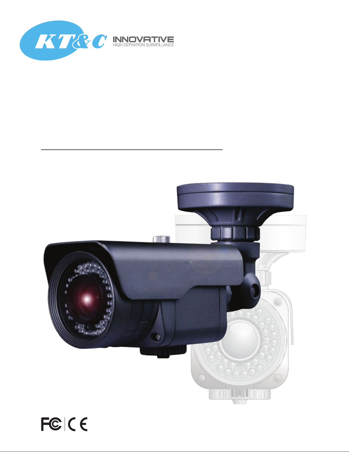
KPC-N635NH10
IR Dual Voltage Varifocal IP66 Bullet Camera
User Guide / Installation / Operation Instructions
www.ktncusa.com
Page 2

Operation Instructions
Please read this manual first for correct installation and operation. This manual should be
retained for future reference. The information in this manual was current when published.
The manufacturer reserves the right to revise and improve its products. All specifications are
therefore subject to change without notice.
Precautions
1. Do not install the camera near electric or magnetic fields.
Install the camera away from TV/radio transmitters, magnets, electric motors, transformers
and audio speakers since the electromagnetic fields generated from these devices may distort
the video image.
2. Never disassemble the camera beyond the recommendations in this manual nor introduce
materials other than those recommended herein.
Improper disassembly or introduction of corrosive materials may result in equipment failure or
other damage.
3. Try and avoid facing the camera toward the sun.
In some circumstances, direct sunlight or may cause permanent damage to the sensor and/or
internal circuits.
4. Keep the power cord away from water and other liquids and never touch the power cord
with wet hands. Touching a wet power cord with hands or touching the power cord with wet
hands may result in electric shock.
5. Never install the camera in areas exposed to oil, gas or solvents.
Oil, gas or solvents may result in equipment failure, electric shock or, in extreme cases, fire.
6. Cleaning
Do not touch the surface of the sensor directly with the hands. Use a damp soft cloth to remove
any dirt from the camera body. Use lens tissue or a cotton tipped applicator and ethanol to
clean the sensor and the camera lens. Please do not use complex solvents, corrosive or abrasive
agents for cleaning.
7. Do not operate the camera beyond the specified temperature, humidity or power source ratings.
Use the camera at temperatures within -20 °C ~ 50 °C (-4 °F ~ 122 °F) and in an IP66 complaint
environment; this device is not rated as submersible. The input power source is 12 V DC/24 V AC.
2
Page 3
Federal Communication Commission Interference Statement
WEE
This equipment has been tested and found to comply with the limits for a Class A digital device,
pursuant to Part 15 of the FCC Rules. These limits are designed to provide reasonable protection
against harmful interference in a residential installation. This equipment generates, uses and can
radiate radio frequency energy and, if not installed and used in accordance with the instructions,
may cause harmful interference to radio communications. However, there is no guarantee that
interference will not occur in a particular installation. If this equipment does cause harmful interference
to radio or television reception, which can be determined by turning the equipment off and on,
the user is encouraged to try to correct the interference by one of the following measures:
* Reorient or relocate the receiving antenna.
* Increase the separation between the equipment and receiver.
* Connect the equipment into an outlet on a circuit different from that to which the receiver
is connected.
* Consult the dealer or an experienced radio/TV technician for help.
FCC Caution: Any changes or modifications not expressly approved by the party responsible for compliance
could void the user's authority to operate this equipment.
This device complies with Part 15 of the FCC Rules. Operation is subject to the following two conditions: (1) This
device may not cause harmful interference
interference that may cause undesired operation.
(2) this device must accept any interference received, including
ATTENTION! This is a class A product which may cause radio interference in a domestic
environment; in this case, the user may be urged to take adequate measures.
This Product is RoHS compliant.
Your KT&C product is designed and manufactured with high quality materials
and components which can be recycled and reused.This symbol means that
electrical and electronic equipment, at their end-of-life, should be disposed
of separately from your household waste.Please, dispose of this equipment
at your local community waste collection/recycling centre.In the European
Union there are separate collection systems for used electrical and electronic
product.
The information in this manual was current upon publication. The manufacturer reserves the right to revise
and improve his products. Therefore, all specifications are subject to change without prior notice. Misprints
reserved. Please read this manual carefully before installing and using this unit. Be sure to keep it handy for
later reference
3
Page 4

Table of Contents
Chapter 1 Product Overview
1.1
Features
1.2
Accessory Parts List
1.3
Specifications
1.4
Dimensions
1.5
Camera Component Description
Chapter 2 Installation
2.1
Wiring and Mounting
2.2
Adjust Camera Position
5
6
7
8
9
10
12
4
Page 5

Chapter 1
1 PRODUCT OVERVIEW
The KT&C KPC-N635NH10 uses 42 IR LEDs with adjustable level control to produce 600TVL day/night
images in low or no light out to a range of 120 feet or more. The KPC-N635NH10 offers flexible
positioning for wall or ceiling mounting in an IP66 weather resistant, vandal resistant bullet
housing with operation down to -4°F; varifocal 2.8-12mm lens with weather resistant screw type
external lens controls for easily adjustable field of view; reflection preventing dual section cover
glass; adjustable IR level to achieve detection range while avoiding interference from reflections; dual voltage 12V DC / 24V AC operation; rapid-mount base plate (base plate is easily
mounted to the wall, camera attaches to base plate with machine screws). This is the economical IR camera that you have been waiting for to create analog CCTV systems that produce outstand-
1.1 Features
• High performance sensor delivers native .01 lux low light sensitivity before IR illumination
• Resolution of over 600 horizontal TV lines for improved image quality
• Flexible positioning for convenient wall or ceiling mounting
• Varifocal 2.8-12mm lens with convenient external adjusters to capture the desired field of view
• Equipped with 42 IR LEDs for 120 foot/40m range (depending on scene IR reflectivity)
• Adjustable IR output level to achieve detection range while avoiding interference from reflections
• Reflection preventing dual section cover glass isolates IR emitters from lens to prevent image distortion
• Video test output point for convenient aim and focus during installation, and ease of service
• Cables protected from weather and tampering by the mounting base
•
screws
• Operating range down to -4 degrees Fahrenheit
• IP66 weather resistant
• Dual voltage (12VDC/24VAC) operation
Convenient rapid-mount base plate easily attaches to surface, camera attaches to plate with machine
5
Page 6

1.2 Accessory Parts List
Please be careful when you unpack the box and the electronic device inside. Check and make sure
that you have all the items listed below inside the original box:
• Camera Unit x 1
• Rapid Mount Ring x 1
• Operation Manual x 1
• Video Test Cable x 1
• Power pigtail x 1
Mounting kit includes:
• Long Screws x 4 (for attaching EZ Mount Ring to mounting surface)
• Short Screws x 4 (for connecting camera base to EZ Mount Ring)
• Expanding Anchors x 4
• Hex key x 1 (for adjusting camera)
• Hexagon wrench x 1 (for adjusting sunshield and set screw in base)
• Mounting Template x 1
Note:
If an item appears to have been damaged in shipment, replace it properly in its carton and notify
the shipper. If any items are missing, notify your KT&C Electronics Corp. Sales Representative or
Customer Service. The shipping carton is the safest container in which the unit may be transported.
Save it for possible future use.
6
Page 7

1.3 Specifications
Imaging Device 1/3" High Sensitivity CCD
Video Format NTSC
Effective Picture Elements 768(H) x 494(V)
Horizontal Resolution More than 600TVL
Sensitivity 0 lux with IR on .01 lux native from sensor
IR LEDs 42 LEDs with output at 850nm and adjustable level
IR Range to 120 feet (depending on scene IR reflectivity)
IR Switch Points On at ~1 lux; Off at ~3 lux
S/N Ratio Over 48dB (AGC off)
Video Output BNC 1.0V p-p 75Ω; video test point inside cover, cable supplied
Gamma Correction 0.45
Lens Type Varifocal 2.8~12mm (electronic iris)
Positioning Flexible positioning for wall or ceiling mounting
Day/Night Electronic D/N
Electronic Shutter 1/60 ~1/100,000 sec.
Sync. Mode Internal
Power Source DC 12 V / AC 24 V
Power Consumption DC 12 V nominal 80 mA; 430 mA IR on
AC 24 V nominal 3 W; 6.6 W IR on
Operating Temperature -4 °F ~ 122 °F ; -20 °C ~ 50 °C
Environmental IP66 weather resistant
Mechanical Metal housing with sun shield; bottom weather sealed access ports for lens
controls, IR level and video test point
Dimensions Body (across sunshield): 4.02” diameter/ 12.34” long w/ sunshield ; 12.34” in line,
longest extension; in 90° position, 10.4” long and 5.77” high
Weight 2.45 pounds
Certifications CE / FCC
7
Page 8

1.4 Dimensions
Camera Body
8
Page 9

1.5 Camera Component Description
Speedy-mount Ring Speedy-mount Ring
Grasp and twist to remove the
cover. Test point and IR level
controls are inside the cover
1
2
1) IR Level Control: adjust IR level to control excessive illumination
2) Video Test : for aim and focus access to video at the camera, use the Video Test Cable supplied to connect to
a hand held test monitor (EN220 or similar).
9
Page 10

Chapter 2
2 INSTALLATION
This chapter will describe, in general terms, how to install the KPC-N635NH10 camera.
STEPS:
1. Wire and mount the camera. See 2.1
2. Adjust the camera position. See 2.2
Warning
To prevent electrical shock, turn off the electrical power before making electrical connections.
2.1 Wiring and Mounting
Use the template and an appropriate tool to drill 4 holes to attach the rapid-mount ring. If no surface wire will be used,
please insert the provided plug into the ring from the underside; the plug will be held securely in place by the ring.
If surface wire access is required, simply omit the plug to leave the surface wire channel clear.
Push the plastic anchors into the 4 holes.
3. Take a long Phillips pan head screw and tighten it through the EZ Mount Ring counter-bored hole into a plastic anchor.
Repeat this step until all 4 screws are secured to the wall/ceiling.
4. Drill a 1” diameter hole within the interior of the EZ Mount Ring.
5. Pull the cables to be connected to power & video cables from the ceiling or wall.
10
Page 11

Video & Power cables
Power Socket
Connect the power and video cables. Attach the camera to the rapid-mount ring, securing it with
the 4 socket head cap screws provided.
Power and Video connection:
11
Page 12

2.2 Adjust Camera Position
Adjust the viewing angle to the desired direction. With this unique 3-axis positioning system, installers can capture images
from virtually any angle, without compromising. The camera can be adjusted in 3 ways.
1st axis
2nd axis
Use a hexagon key to loosen this screw
to rotate the camera 360°
Use a hexagon key to loosen this screw
to rotate the camera 180°
12
Page 13

3rd axis
12
Loosen lock ring and set screw to rotate camera 360°
Sunshield
To remove or install the sunshield, use flat blade screw driver to loosen the screw at sunshield.
Secure with this screw
Note: When properly installed, the rear of the sunshield is even with the rear of the camera body; improperly extending
the sunshield to ‘shade’ the lens can compromise image quality.
13
 Loading...