

Page 1
M097-LP500-002
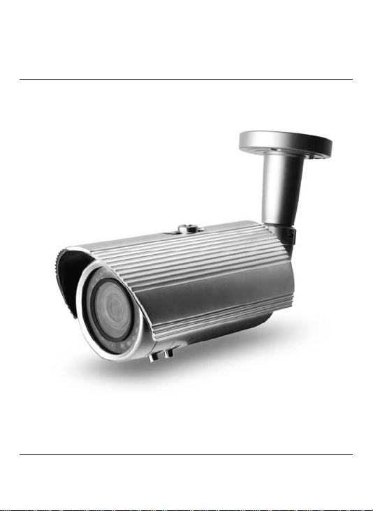
High Contrast License Plate
Capture Camera
OPERATION MANUAL
Thank you for choosing our high quality camera.
Before attempting to connect operate this unit, please read and follow these instructions.
Page 2

Contents
1. CAUTIONS
2. FEATURES
3. COMPONENTS
4. NAME AND FUNCTION
5. INSTALLATION
6. FUNCTIONS
7. TARGET MARKETS
8. INSTALLATION GUIDELINE
9. SPECIFICATION
10. DIMENSIONS
2
Page 3
1. Cautions
This device complies with Part 15 of the FCC Rules.
Operation is subject to the following two conditions;
1. This device may not cause harmful interference.
2. This device must accept any interference received, including
interference that may cause undesired operation.
Note -
This equipment has been tested and found to comply with the limits
for a Class A digital device, pursuant to part 15 of the FCC Rules.
These limits are designed to provide reasonable protection against
harmful interference when the equipment is operated in a commercial
environment. This equipment generates, uses, and can radiate radio
frequency energy and, if not installed and used in accordance with
the instruction manual, may cause harmful interference to radio
communications. Operation of this equipment in a residential area
is likely to cause harmful interference in which case the user will be
required to correct the interference at his own expense.”
WARNING -
This is a class A product. In a domestic environment this product may
cause radio interference in which case the user may be required to take
adequate measures.
Caution -
Any changes or modifications in construction of this device which are
not expressly approved by the party responsible for compliance could
void the user’s authority to operate the equipment.
1. A regulated DC12V 1A power supply is recommended for use with this camera
for the best picture and the most stable operation.
An unregulated power supply can cause damage to the camera.
When unregulated power supply is applied, product warranty will be
out of subject.
2. It is recommended that the camera is used with a monitor that has a CCTV quality
75 video impedance level.
If your monitor is switched to high impedance then please adjust accordingly.
3. Do not attempt to disassemble the camera to gain access to the internal componets.
Refer servicing to your dealer.
4. Never face the camera towards the sun or any bright or reective light, which may
cause smear on the picture and possible damage to the CCD.
5. Do not remove the serial sticker for the warranty service.
3
Page 4
1. Cautions
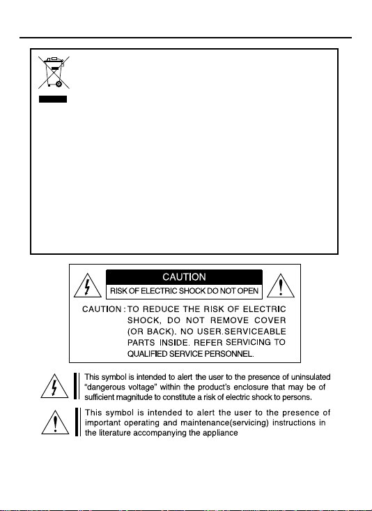
Correct Disposal of This Product
(Waste Electrical & Electronic Equipment)
(Applicable in the European Union and other European countries with
separate collection systems)
This marking shown on the product or its literature, indicate that it should not
be disposed with other household wastes at the end of its working life. To
prevent possible harm to the environment or human health from uncontrolled
waste disposal, please separate this from other types of wastes and recycle it
responsibly to promote the sustainable reuse of material resources.
This product should not be mixed with other commercial wastes purchased this
product, or their local government ofce, for details of where and how they can
take item for environmentally safe recycling.
Business users should contact their supplier and check the terms and
conditions of the purchase contract.
Household users should contact either the retailer where they for disposal.
4
Page 5
2. Features
• 1/3" Sony Super-HAD CCD
• High Resolution 600TV Lines
• Special filter and IR LED provides maximum readability
despite headlight glare
• Plate capture up to 35mph (56Km/H)
• 9.0 ~ 22.0mm Varifocal Lens captures license plate
from 8ft ~ 60ft (2.5M ~ 18.5M)
• IP66 rated weather proof
• Cable through concealed bracket
• DC12V / AC24V Dual power with auto-polarity
Ⅱ
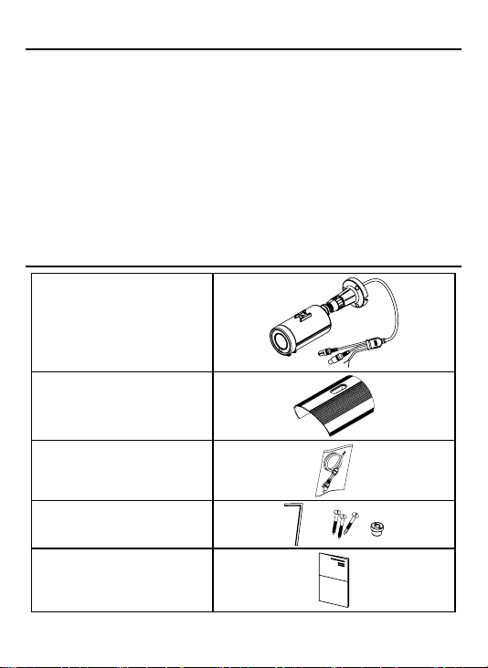
3. Components
CAMERA
SUNSHIELD
VIDEO OUTPUT
TEST CABLE
L-WRENCH /
SCREW - 3ea /
SUNSHIELD FIXING BOLT
OPERATION MANUAL
5
Page 6

4. Name and Function
①
①
②
③
④
⑤ ⑧
①
Sunshield Lock Bolt
②
Sunshield
③
Mounting Bracket
④
IR LED : 20ea
⑤
Camera Body
⑥
Body Lock Ring
⑦
External Zoom and Focus adjustments
⑥
⑦
⑦
TEST
VIDEO
OUTPUT
⑧
Cover To Access Menu Controls & Test Video Output
Pressing the “SETUP” button prompts the main setup menu.
“PUSH” button : To access the main setup menu
“U” Direction : Menu item UP selection
“D” Direction : Menu item DOWN selection
“L” Direction : To change data or decrease value
“R” Direction : To change data or increase value
6
Page 7

5. Installation
• MOUNTING POSITION
˚
360
Loosen socket head allen screws to change angle
and/or rotate body about base.
After adjusting zoom and focus,
to prevent water infiltration, firmly
tighten the zoom and focus levers.
˚
90
Loosen this lock ring
to rotate camera body.
360
˚
WARNING !
To prevent injury, this apparatus must be securely
attached to the mounting surface with sufficient
strength to hold the weight of the camera including
wind and snow loading in accordance with the
installation instructions.
7
360
˚
Page 8

5. Installation
• MONITOR CONNECTION
DC12V / DUAL(DC12V/AC24V)
VIDEO TEST POINT
CONNECTION
DC12V
(DC12V/AC24V)
BNC FEMALE
WHITE: TRIGGER SIGNAL
BLACK: TRIGGER GROUND
DC12V POWER SUPPLY
(DC12V /AC24V POWER SUPPLY)
VIDEO IN
OSD CONTROL
VIDEO IN
TEST CABLE
Note: Face of connector with color mark should
face “up” when inserting test cable.
When you install the camera, please glue up the end of cable to
keep it stable in order to protect the camera from the humidity problems.
HANDHELD
8
Page 9

6. Functions
OSD Menu Structure
• MODE
- INSTALLATION
Installation Mode provides bright
video screen to adjust angle and focus.
- LICENSE-PLATE
License-plate Mode provides high contrast
and clear license plate image for license
plate capture.
• SHUTTER
1/250, 1/500, 1/1,000 ~ 1/10,000.
(After 1/1000sec, 1/500sec unit adjustment)
- Adjusted when LICENSE-PLATE MODE is performed.
(Initial value: 1/250)
- Indicated “---” when INSTALLATION MODE is set.
• FREEZE
The video screen will automatically go
in to FREEZE mode when Camera is
triggered by sensors. User can set the
freeze time to 3, 5, or 10 sec.
• NEGATIVE
User can select positive or negative image.
Negative OFF
Negative ON
7. Target Markets
• Government
• Military
• Hotels and Casinos
• Parking Lots
• Border Patrol
• Gated Communities
• Traffic monitoring
• Embassies
• Ports
• College Campus
• Airports
• Law Enforcement
• Toll Booths
• Security
9
SETUP
▶
MODE
SHUTTER
FREEZE-TIME
NEG. IMAGE
EXIT
SETUP
MODE
SHUTTER
▶
FREEZE-TIME
NEG. IMAGE
EXIT
SETUP
MODE
SHUTTER
FREEZE-TIME
▶
NEG. IMAGE
EXIT
SETUP
MODE
SHUTTER
FREEZE-TIME
▶
NEG. IMAGE
EXIT
LICENSE-PLATE
LICENSE-PLATE
LICENSE-PLATE
LICENSE-PLATE
1/250
5SEC
OFF
1/250
5SEC
OFF
1/250
5SEC
OFF
1/250
5SEC
OFF
Page 10

8. Installation Guideline
Camera Height
Must consider height in distance calculation.
•
Sharper angle will alter appearance of plate.
•
Camera Height (Ft) Horizontal Distance (Ft) Capture Distance(Ft)
10 10 14.14
11 20 22.83
12 30 32.31
13 40 42.06
14 50 51.92
10
Page 11

8. Installation Guideline
Camera Angles
Vertical and horizontal angle must not exceed 40 degrees to
•
get optimal view of the license plate.
Capture Zone
Wider angle provide shorter capture distance.
•
Tele angle provide longer capture distance.
•
11
Page 12

8. Installation Guideline
Lane Width
Narrow lanes = less variation in plate location.
•
Wider lanes = more variation in plate location.
•
Lens should cover entire width of the lane.
•
Ensure horizontal eld of view is wide enough.
•
Speed
Camera can capture moving vehicles up to 35mph.
•
Keep camera as low as possible.
•
Minimize horizontal angle.
•
Zoom in the lens as close as possible.
•
Up to 35 mph
12
Page 13

8. Installation Guideline
Trigger
Camera support trigger input for freezing video screen.
•
Connect external sensor e.g. Parking Gate Sensor.
•
Trigger input should be pulled-up 3.3V DC in normal condition.
•
Input line will be triggered when pull-up 3.3V DC drop to GND.
•
DVR
Camera is fully compatible with industry standard DVRs.
•
Check compression settings.
•
Non-conditional refresh compression. (i.e. MJPEG or JPEG)
•
D1 (720x480) resolution.
•
30fps (each channel) for best results.
•
13
Page 14

9. Specification
Signal Format NTSC PAL
Image Device 1/3" Sony Super HAD CCD
Total Pixels 811(H) x 508(V) 795(H) x 596(V)
Effective Pixels 768(H) x 494(V) 752(H) x 582(V)
Inter. H/V 15.734KHz(H), 59.94Hz(V) 15.625KHz(H), 50Hz(V)
H.Resolution 600TV Lines
Minimum illumination 0 Lux (IR LED ON)
S/N Ratio More than 50dB (AGC Off)
Sync System Internal
Video Output 1.0 Vp-p Composite(75Ω)
Lens Varifocal
IR LED 850nm, 20ea
IP Rating IP66
Speed Rage Up to 35mph (56km/h)
License
Plate
Capture Distance 8ft ~60ft (2.5m~18.5m)
Capture
Capture Angle Maximum 40 degree offset
Operating Temperature 14˚F~122˚F(-10˚C ~ +50˚C)
Storage Temperature -4˚F~140˚F(-20˚C ~ +60˚C)
Power
Consumption
Weight Approx. 1000g
Dinmension(mm) 82 x 79.3 x 130
Option DUAL(AC24V/DC12V)
Specications and designs are subject to change for improving the functionality of this product without notice.
DC12V DC12V ±10% Max 450mA
DUAL
DC12V ±10% Max 570mA
AC24V ±10% Max 6.7W
Ⅱ
14
Page 15

10. Dimensions
unit: mm
87.8
Ф
3.5(Ф0.14)
120 degree
145
120
25.98 (
Ф
120 degree
82
224
M12 XP 1.0
1.02)
Ф
7
100
Bottom of Bracket
Ф
65
15
Page 16

Mount Guide
3-ø5.3
 Loading...