

Page 1
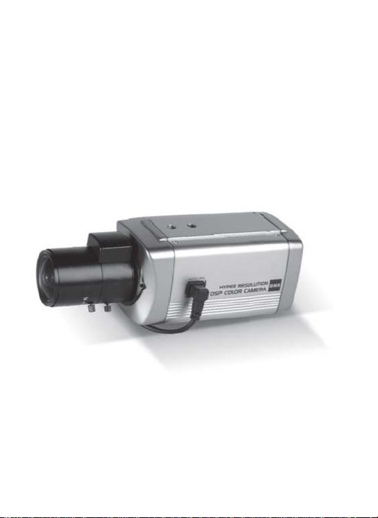
HIGH RESOLUTION
DSP COLOR CAMERA
OPERATION MANUAL
M101-DN6300-002
Thank you for choosing our high quality camera.
Before attempting to connect operate this unit, please read and follow these instructions.
Page 2

CONTENTS
1. CAUTIONS
2. FEATURES
3. COMPONENTS
4. NAME AND FUNCTION
5. INSTALLATION
6. DIMENSIONS
7. SPECIFICATION
8. OSD MENU STRUCTURE
2
Page 3

1. CAUTIONS
This device complies with Part 15 of the FCC Rules.
Operation is subject to the following two conditions;
1. This device may not cause harmful interference.
2. This device must accept any interference received, including
interference that may cause undesired operation.
Note
This equipment has been tested and found to comply with the limits for a Class A digital
device, pursuant to part 15 of the FCC Rules. These limits are designed to provide
reasonable protection against harmful interference when the equipment is operated
in a commercial environment. This equipment generates, uses, and can radiate radio
frequency energy and, if not installed and used in accordance with the instruction
manual, may cause harmful interference to radio communications. Operation of this
equipment in a residential area is likely to cause harmful interference in which case the
user will be required to correct the interference at his own expense.”
WARNING
This is a class A product. In a domestic environment this product may cause radio
interference in which case the user may be required to take adequate measures.
Caution
Any changes or modications in construction of this device which are not expressly
approved by the party responsible for compliance could void the user’s authority to
operate the equipment.
1. A regulated DC12V 500mA power supply is recommended for use with this camera
for the best picture and the most stable operation.
An unregulated power supply can cause damage to the camera.
When unregulated power supply is applied, product warranty will be out of subject.
2. It is recommended that the camera is used with a monitor that has a CCTV quality
75 video impedance level.
If your monitor is switched to high impedance then please adjust accordingly.
3. Do not attempt to disassemble the camera to gain access to the internal componets.
Refer servicing to your dealer.
4. Never face the camera towards the sun or any bright or reective light, which may
cause smear on the picture and possible damage to the CCD.
5. Do not remove the serial sticker for the warranty service.
6. Do not expose the camera to rain or other types of liquid.
7. The apparatus must be connected to a mains socket-outlet with a protective earthing
connection.
3
Page 4
1. CAUTIONS
Correct Disposal of This Product
(Waste Electrical & Electronic Equipment)
(Applicable in the European Union and other European countries with
separate collection systems)
This marking shown on the product or its literature, indicate that it should not
be disposed with other household wastes at the end of its working life. To
prevent possible harm to the environment or human health from uncontrolled
waste disposal, please separate this from other types of wastes and recycle it
responsibly to promote the sustainable reuse of material resources.
This product should not be mixed with other commercial wastes purchased this
product, or their local government ofce, for details of where and how they can
take item for environmentally safe recycling.
Business users should contact their supplier and check the terms and
conditions of the purchase contract.
Household users should contact either the retailer where they for disposal.
4
Page 5
2. FEATURES
• 1/3 SONY EXview HAD CCD II
• High Resolution of 700TV Lines
• OSD Function
• Multi Language
(ENGLISH / JAPANESE / GERMAN / FRENCH / RUSSIAN / PORTUGUESE / SPANISH / CHINESE)
• 2DNR
• Privacy Zone
• Motion Detect
• DC12V / AC24V Dual Voltage
• ATR(Adaptive Tone-curve Reproduction / Digital WDR)
The function provides gradation compensation to improve the contrast of subjects both
low-luminance areas and high luminance areas exist in the same picture
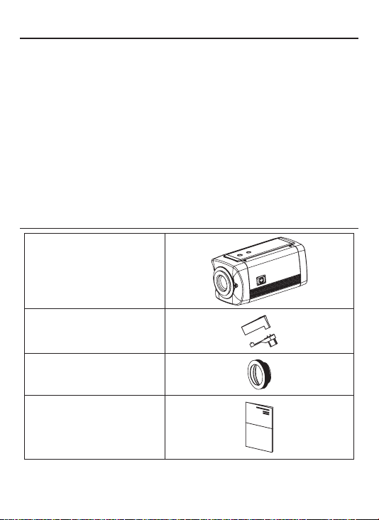
3. COMPONENTS
DSP Color Camera
AUTO IRIS LENS
CONNECTION PLUG
C-MOUNT ADAPTOR RING
OPERATION MANUAL
5
Page 6

4. NAME AND FUNCTION
• FRONT
TRIPOD MOUNTING HOLE(1/4"-20 UNC)
C-MOUNT ADAPTOR RING
MOUNT COVER
CS-MOUNT ADAPTOR RING
CS-MOUNT ADAPTOR RING
FIXING SCREW(2EA)
• BACK
①. MENU BUTTON
②. UP BUTTON
③. DOWON BUTTON
④. LEFT BUTTON
⑤. RIGHT BUTTON
⑥. POWER LED
(The LED turns on when power is supplied)
⑦. VIDEO OUT JACK
(Used to connect an external video monitor in jack)
⑧. POWER TERMINAL
(User to connect an DC12V power source)
(Options : AC 24V/DC12V)
AUTO IRIS JACK
TRIPOD MOUNTING HOLE(1/4"-20 UNC)
①
④
③
6
②
⑤
⑦
⑧
Class 2 Only
⑥
Page 7

5. INSTALLATION
• LENS CONNECTION
Lenses are sold separately. Lenses such as an auto iris lens,
CS-Mount lens and C-Mount lens can be used.
NOTE
• Please keep the lens clean.
• Any foreign objects and Finger marks on the lens can cause
inferior image quality in low light level conditions.
When using an auto iris lens
1. Please peel off about 8mm of the outer skin of the auto iris lens cable.
2. Please peel off about 2mm of the outer skin of the insulated conductor
inside the lens cable.
7
Page 8

5. INSTALLATION
3. Please remove the cover of the auto iris lens connection plug and
solder the lens cable to the connector pin in the plug.
* PIN ASSIGNMENT OF THE LENS CONNECTOR
1) DC auto iris lens
Pin 1: DAMP-(CTL-)
Pin 2: DAMP+(CLT+)
Pin 3: DRV+
Pin 4: DRV-(GND)
4. Please replace the auto iris lens connection plug cover and take off the
Sensor protection cap and then attach the auto iris lens to the camera by
screwing it in clockwise.
8
Page 9

5. INSTALLATION
5. Please insert the connection plug that is connected to the auto iris lens
cable into the auto lens connector, which is located on the side of the camera
9
Page 10

5. INSTALLATION
Installation of C-Mount Lens
CS-MOUNT ADAPTOR RING
C-MOUNT ADAPTOR RING
Installation of CS-Mount Lens
CS-MOUNT ADAPTOR RING
10
Page 11

5. INSTALLATION
• MONITOR CONNECTION
(1) DC12V
Class 2 Only
BNC FEMALE
VIDEO
DC12V REGULATED
POWER SUPPLY
VIDEO IN
(2) DC12V/AC24V
BNC FEMALE
DC12V/AC24V
Class 2 Only
* As the connecting method varies with instruments, refer to the
manual supplied with the instrument.
* Only connect the cable when the power is turned off.
* Set the 75Ω / Hi-Z selection switch as shown below if you have an
intermediate device
Class 2 Only
VIDEO
DC12V / AC24V REGULATED
POWER SUPPLY
11
VIDEO IN
Page 12

6. DIMENSIONS
Unit(mm)
1/4"-20 UNC
58
58
110.4
109
12
Page 13

7. SPECIFICATION
Signal Format NTSC PAL
Image Device 1/3˝ SONY EXview HAD CCD II
Scanning System 2 : 1 Interlace
Scanning Frequency 15.734KHz(H), 59.94Hz(V) 15.625KHz(H), 50Hz(V)
Total Pixels 1020(H) X 508(V) 1020(H) X 596(V)
Effective Pixels 976(H) X 494(V) 976(H) X 582(V)
H.Resolution 750TV Lines
S/N Ratio More than 50dB(AGC OFF)
Min.Illumination
Sync System Internal
Gamma r= 0.45
Video Output Level 1.0 Vp-p Composite(75Ω)
OSD Built in
BLC OFF/BLC/HLC
2DNR OFF/ON(Level adjustable)
ATR OFF/ON(Level adjustable)
Function
White Balance
Privacy Masking 4 Zones
Motion Detection 4 Zones
Day & Night(ICR) AUTO / COLOR / BW
Language
Operating Temperature 14°F~122°F(-10°C~+50°C)
Storage Temperature -4°F~140°F(-20°C~+60°C)
Humidity Less than 80%
Dimension 58(W) x 58(H) x 110.4(D)
Power
Consumption
Lens MANUAL/DC
Specications and designs are subject to change for improving the functionality of this product without notice.
DC12V DC12V(±10%), Max. 130mA
DUAL
ENGLISH / JAPANESE / GERMAN / FRENCH / RUSSIAN /
0.05Lux(Color) / 0.003Lux(BW)
(30IRE@F1.4)
MIRROR / BRIGHTNESS / CONTRAST /
SHARPNESS / HUE / GAIN
ATW / PUSH / USER1 / USER2 /
ANTI CR / MANUAL / PUSH-LOCK
PORTUGUESE / SPANISH / CHINESE
AC24V(±10%), Max. 2.9W
DC12V(±10%), Max. 180mA
13
Page 14

8. OSD MENU STRUCTURE
MAIN
MENU
LENS
1st Sub
MENU
MANUAL
AUTO
AUTO
SHUTTER
/ AGC
MANUAL
ATW
PUSH
USER1
WHITE
BAL
USER2
ANTI CR
MANUAL
PUSH LOCK
BACK LIGHT OFF,BLC,HLC
MIRROR
BRIGHTNESS
CONTRAST
PIC
SHARPNESS
ADJUST
HUE
GAIN
RETURN
ON
ATR
OFF
*SHUT+IRIS:
*Auto Iris(Default): The Shutter stays at the manually selected value and only the Mechanical Iris adjusts to brightness.
Both the Shutter and the Mechanical Iris are automatically adjusted according to brightness.
2nd Sub
MENU
TYPE DC
MODE AUTO,OPEN,CLOSE
SPEED (000 ~ 255)
RETURN
HIGH LUMINANCE
LOW LUMINANCE
RETURN
MODE SHUT+AGC
SHUTTER
AGC 6,12,18,24,30,36,42,44.8
RETURN
SPEED (000 ~ 255)
DELAY CNT (000 ~ 255)
ATW FRAME x0.50,x1.00,x1.50,x2.00
ENVIRONMENT INDOOR,OUTDOOR
RETURN
B-GAIN (000 ~ 255)
R-GAIN (000 ~ 255)
RETURN
B-GAIN (000 ~ 255)
R-GAIN (000 ~ 255)
RETURN
LEVEL 24 ~ 103
RETURN
OFF,ON
(000 ~ 255)
(000 ~ 255)
(000 ~ 255)
(000 ~ 255)
(000 ~ 255)
LUMINANCE LOW,MID,HIGH
CONTRAST LOW,MIDLOW,MID,MIDHIGH,HIGH
RETURN
3rd Sub
MENU
MODE SHUT,AUTO IRIS, SHUT+AUTO IRIS
BRIGHTNESS (000 ~ 255)
MODE AGC,OFF
BRIGHTNESS x0.25,x0.50,x0.75,x1.00
1/50(PAL),1/100(NTSC)
1/60(NTSC),1/120(PAL)
1/250,1/500,1/1000
1/2000,1/4000,1/10000
14
4th Sub
MENU
Page 15

8. OSD MENU STRUCTURE
MAIN
MENU
MOTION
DET
NEXT
EXIT
SAVE ALL
PRIVACY
DAY/
NIGHT
NR
CAMERA
ID
LANGUAGE ENGLISH, 日本語, DEUTSCH, FRANCAIS,
CAMERA
RESET
BACK
EXIT
SAVE ALL
*Important Note
Else all changes will be discarded.
- By changing the lens option in the OSD from MANUAL to AUTO will automatically change the
SHUTTER/AGC setting from AUTO IRIS to SHUT+AUTO IRIS.(Default:AUTO IRIS)
1st Sub
MENU
ON
OFF
ON
OFF
AUTO
COLOR
BW
NR MODE OFF,Y,C,Y/C
C LEVEL (000 ~ 015)
Y LEVEL (000 ~ 015)
RETURN
ON EDIT MODE
OFF
- Any changes made to the camera settings must be saved prior to exiting the OSD menu.
:
2nd Sub
MENU
DETECT SENSE
BLOCK DISP
MONITOR AREA
AREA SEL
RETURN
AREA SEL
COLOR
TRANSP
MOSAIC
RETURN
BURST
DELAY CNT
DAY > NIGHT
NIGHT > DAY
RETURN
RETURN
3rd Sub
MENU
(000 ~ 255)
OFF,ON,ENABLE (CONTROLER)
ON,OFF
1/4, 2/4, 3/4, 4/4
TOP NTSC:(000 ~ 244) / PAL: (000 ~ 288)
BOTTOM NTSC:(000 ~ 244) / PAL: (000 ~ 288)
LEFT NTSC:(000 ~ 474) / PAL: (000 ~ 468)
RIGHT NTSC:(000 ~ 474) / PAL: (000 ~ 468)
1/4, 2/4, 3/4, 4/4
TOP NTSC:(000 ~ 244) / PAL: (000 ~ 288)
BOTTOM NTSC:(000 ~ 244) / PAL: (000 ~ 288)
LEFT NTSC:(000 ~ 474) / PAL: (000 ~ 468)
RIGHT NTSC:(000 ~ 474) / PAL: (000 ~ 468)
(1 ~ 8)
0.00, 0.50, 0.75, 1.00
OFF,ON
OFF,ON
0 ~ 255
0 ~ 255
0 ~ 255
Русский,
PORTUGUÊS, ESPAÑOL, 中文
15
4th Sub
MENU
 Loading...