

Page 1

CONFIDENTIAL - This document is the property of K.T.C. S.r.l. and cannot be reproduced or issued to third parties without written
authorization. K.T.C. shall safeguard its rights to the full extent of the law.
USER MANUAL AND INSTALLATION
COD. 091052 - REV. 07 - DATE 11/2016
Pag.1 di 45
OPERATION AND MAINTENANCE MANUAL FOR
COMPACK 2 COMPRESSOR
(SOLUTION FOR BUS)
ENGLISH VERSION
Page 2

CONFIDENTIAL - This document is the property of K.T.C. S.r.l. and cannot be reproduced or issued to third parties without written
authorization. K.T.C. shall safeguard its rights to the full extent of the law.
USER MANUAL AND INSTALLATION
COD. 091052 - REV. 07 - DATE 11/2016
Pag.2 di 45
SUMMARY
1 GENERAL WARNINGS AND INFORMATION FOR THE USER ................... 4
1.1 DEFINITION OF REGULATED RELATIONSHIPS ................................................... 4
1.1.1 DECLARATIONS .............................................................................................. 4
1.1.2 WARRANTY...................................................................................................... 5
1.1.3 RETURNS .......................................................................................................... 5
1.2 RULES APPLY .............................................................................................................. 6
1.3 GENERAL INFORMATION ......................................................................................... 6
1.3.1 WARNINGS AND PRECAUTIONS ................................................................. 6
1.4 HOW TO SEE THE MANUAL ..................................................................................... 6
1.5 CE MARKING ............................................................................................................... 7
1.6 MAINTENANCE AND SUPPORT INFORMATION OF THE MACHINE................ 8
1.7 INSTRUCTIONS FOR SAFE OPERATION................................................................. 8
1.8 LABELS POSITION .................................................................................................... 11
2 TECHNICAL DATA COMPRESSOR ................................................................ 14
3 DIMENSIONS...................................................................................................... 15
4 UNPACKING ....................................................................................................... 17
5 LOCATION .......................................................................................................... 17
6 CONNECTION AND START UP ...................................................................... 19
6.1 GENERAL WARNINGS ............................................................................................. 19
6.2 USE OF THE COMPRESSOR ..................................................................................... 20
6.3 COMPRESSOR LUBRICATION ................................................................................ 21
6.4 USING THE COMPRESSOR WITH SYNTHETIC OILS .......................................... 22
6.5 CONNECTION AND START UP ............................................................................... 23
6.5.1 GENERAL WARNINGS ................................................................................. 23
6.5.2 CONNECTING OF THE POWER CABLE OF COMPRESSOR ................... 23
6.6 ELECTRICAL CONNECTION OF COMPRESSOR .................................................. 24
6.6.1 FUSE AND BREAKER.................................................................................... 24
6.6.2 GROUND CONNECTION ............................................................................... 25
6.6.3 SIZING OF ELECTRIC CABLE ..................................................................... 25
Page 3

CONFIDENTIAL - This document is the property of K.T.C. S.r.l. and cannot be reproduced or issued to third parties without written
authorization. K.T.C. shall safeguard its rights to the full extent of the law.
USER MANUAL AND INSTALLATION
COD. 091052 - REV. 07 - DATE 11/2016
Pag.3 di 45
6.7 AIR CONNECTION OF COMPRESSOR ................................................................... 26
7 FIRST START ...................................................................................................... 27
8 CONTROL PANEL ............................................................................................. 28
8.1 ELECTRIC DIAGRAM ............................................................................................... 29
9 HEATING RESISTANCE OF OIL ..................................................................... 33
10 PNEUMATIC SCHEME AND MACHINE DESCRIPTION ............................. 34
11 ORDINARY MAINTENANCE OF COMPRESSOR ......................................... 35
11.1 REPLACEMENT OF OIL FILTER ............................................................................. 37
11.2 REPLACEMENT OF SEPARATOR FILTRE............................................................. 37
11.3 CHANGING OIL .......................................................................................................... 38
11.4 REPLACEMENT OF AIR FILTER ............................................................................. 39
12 MAINTENANCE SCHEDULE ........................................................................... 40
13 TROUBLESHOOTING ....................................................................................... 42
14 APPENDIX .......................................................................................................... 44
14.1 MAINTENANCE CONTROL BOARD ...................................................................... 44
15 COMMERCIAL PARTS, SPARE PARTS AND RELATED
DOCUMENTATION .......................................................................................... 45
Page 4

CONFIDENTIAL - This document is the property of K.T.C. S.r.l. and cannot be reproduced or issued to third parties without written
authorization. K.T.C. shall safeguard its rights to the full extent of the law.
USER MANUAL AND INSTALLATION
COD. 091052 - REV. 07 - DATE 11/2016
Pag.4 di 45
1 GENERAL WARNINGS AND INFORMATION FOR THE USER
1.1 DEFINITION OF REGULATED RELATIONSHIPS
1.1.1 DECLARATIONS
The compressor must be used solely as indicated in this manual. This manual must be kept
on hand in a known, easily accessible place because it should be used throughout the
machine's entire working life.
When making any requests, always indicate model and serial number.
TEST CERTIFICATE
We hereby declare that the compressor has passed testing.
The following checks were performed:
-All parts have been assembled correctly and are functioning properly;
-The unit has passed electrical testing;
-The pressurized parts have passed testing;
-There are no leakages in the oil and air circuits;
-The outside of the machine is not defective;
-The air yield, power consumption and operating temperature parameters are all within normal
ranges;
The Tester
________________
DECLARATION OF CONFORMITY
K.T.C. S.r.l., the manufacturer, on its own responsibility, declares that the air compressor identified
by the label on the front page of this document, complies with the essential requirements laid out in
the following DIRECTIVES – STANDARDS
2009/105/CE - 2014/35/CE – 2006/42/CE – 2014/30/CE - EN60204-1 - EN1012-1
K.T.C. S.r.l. holds the relevant technical dossier.
Page 5

CONFIDENTIAL - This document is the property of K.T.C. S.r.l. and cannot be reproduced or issued to third parties without written
authorization. K.T.C. shall safeguard its rights to the full extent of the law.
USER MANUAL AND INSTALLATION
COD. 091052 - REV. 07 - DATE 11/2016
Pag.5 di 45
1.1.2 WARRANTY
The KTC S.R.L guarantees its products from manufacturing or design defects for a period of 24
months from the date of commissioning, which must be communicated to KTC S.R.L, filling out
the form within the technical documentation supplied with the machine.
Not getting no communication, the guarantee will be recognized for 24 months by referring to the
following shipment date on the sales invoice KTC S.R.L.
Are excluded from the warranty the components for their specific use is subject to usury.
Interventions under warranty can be made exclusively by KTC SR.L. or technical assistance centres
authorized by KTC SR.L. shipment of any product made to KTC S.R.L, for Interventions under
warranty must be authorized in advance in writing by KTC S.R.L, which decides in its sole
discretion whether to authorise or use of its own Authorized technical assistance Center.
In both cases, the expedition to KTC S.R.L will be prepaid with the charge of the shipping invoice.
Repair or replacement under warranty includes free replacement of machine components, defective
recognized.
The warranty lapses for damage caused by negligence, incorrect installation, use and or do not
comply with the instructions described in "use and maintenance booklet"; in the case of alterations
or repairs carried out with non-original spare parts or by KTC S.R.L personnel not authorized by
KTC S.R.L.
Defective items replaced under warranty, are withdrawn from the authorized service center. Are
excluded from any warranty repair or compensation for damages occurring during transport (oneway or return from an authorized technical assistance Center). Is any type of compensation for
damage caused to persons or things, resulting from a failure and inappropriate use of purchased and
downtime (the customer must protect itself for this case).
Warranty service is provided only to buyer in compliance with contractual and administrative rules
that present the specification documentation attesting to the purchase period.
This is the only valid warranty recognized by KTC S.R.L JURISDICTION.
Any dispute will be exclusively the competence of the courts of Vicenza.
1.1.3 RETURNS
Returns are made using the RMA (return material authorization) procedure.
To open said procedure, the customer must send a request to KTC.
Page 6

CONFIDENTIAL - This document is the property of K.T.C. S.r.l. and cannot be reproduced or issued to third parties without written
authorization. K.T.C. shall safeguard its rights to the full extent of the law.
USER MANUAL AND INSTALLATION
COD. 091052 - REV. 07 - DATE 11/2016
Pag.6 di 45
1.2 RULES APPLY
As expressed in the declaration of conformity (chap. 1.1.1), the air compressor is identified by the
label on the front of this document complies with the essential requirements of DIRECTIVE - LAW
2009/105/CE - 2014/35/CE – 2006/42/CE – 2014/30/CE - EN60204-1 - EN1012-1
1.3 GENERAL INFORMATION
The compressor should be used only as indicated in this manual, which should be stored carefully in
a place easily accessible and familiar, since it will follow the entire life of the machine.
For any requests always specify model and serial number.
1.3.1 WARNINGS AND PRECAUTIONS
Before each operation, read carefully this user manual. Failure of the information and instructions
contained in it can cause damage to property and injury to persons.
• The machine was designed and built for the following functions. Any other commitment is not
allowed.
• Installation and maintenance must be performed by qualified personnel. Always follow the safety
rules.
• The manufacturer disclaims any liability for damage to persons or things to the machine in
question, caused by incorrect use of the same, failure or superficial compliance with security
policies in this manual, by even slight changes, from use of non-original spare parts.
1.4 HOW TO SEE THE MANUAL
Symbols have been identifying situations requiring extra attention. These symbols may appear next
to a text, a picture next to or on top of the page. Give full attention to the meaning of the symbols:
their function is to avoid repeating the key terms or notices of darkness, to be considered
"reminders". See the page below whenever doubts arise about their meaning.
WARNING: This highlights an important description regarding hazardous
conditions, safety warnings, information of utmost importance.
MACHINE STOPS: Each operation must be performed with the machine stopped
ATTENTION MACHINE IN PRESSURE: every operation must be performed for a
machine without pressure in the air/oil separator tank (0 bar).
Page 7

CONFIDENTIAL - This document is the property of K.T.C. S.r.l. and cannot be reproduced or issued to third parties without written
authorization. K.T.C. shall safeguard its rights to the full extent of the law.
USER MANUAL AND INSTALLATION
COD. 091052 - REV. 07 - DATE 11/2016
Pag.7 di 45
REMOVE POWER: every operation must be performed on the machine when the
power is turned off.
QUALIFIED: any intervention highlighted by this symbol is the exclusive competence
of a technician
1.5 CE MARKING
The CE marking certifies that the compressor complies with the health and safety requirements
outlined in the European Directives indicated in the EC declaration of conformity.
The marking is printed with silver lettering on a black polyester adhesive label (L:90mm H:80mm).
The label is placed as indicated in figure 1 and bears the following information:
CE marking
Compressor model
Serial number
Maximum working pressure
Power supply voltage and frequency
Nominal power
Weight
Manufacture year
Page 8

CONFIDENTIAL - This document is the property of K.T.C. S.r.l. and cannot be reproduced or issued to third parties without written
authorization. K.T.C. shall safeguard its rights to the full extent of the law.
USER MANUAL AND INSTALLATION
COD. 091052 - REV. 07 - DATE 11/2016
Pag.8 di 45
1.6 MAINTENANCE AND SUPPORT INFORMATION OF THE MACHINE
Our assistant service is at your disposal to provide all information necessary to resolve any
problems that might arise.
For further information please contact customer service or your local dealer.
Only with the use of original spare parts can guarantee the best performance of the our
compressor.
Please observe the instructions given in chapter maintenance and use only original spare parts.
The use of the non original spare parts will automatically make void the warranty.
1.7 INSTRUCTIONS FOR SAFE OPERATION
WARNING!
Below is a list of important instructions for safe use of the compressor. Follow
these instructions carefully. Improper use or maintenance of the compressor can
cause injury to the user.
1. Never Touch any Moving Parts
Never allow parts of the body to come near moving parts of the machine.
2. Never Use the Compressor if the Protection Guards have been Removed
Never use the compressor unless all guards are assembled. If maintenance requires removing any of
the guards, make sure that they are properly reinstalled before starting up the unit. Never bypass the
safety devices installed on the compressor. This is strictly forbidden.
3. Protective Grids
Never insert objects or body parts into protective grids as this can cause injury and can damage the
compressor.
4. Use the Compressor Correctly
Always operate the compressor following the instructions given in this manual. Never allow
children or unauthorized persons to use the compressor.
5. Always Wear Eye Protection
Always wear goggles or other equivalent form of eye protection. Do not direct air toward parts of
the body, your own or others.
6. Work Clothing
Do not wear inappropriate clothing or accessories. If necessary, wear a cap that covers the hair.
7. Use the Compressor Sensibly
Never use the compressor while under the effect of alcohol, drugs or medications that can cause
drowsiness.
8. Personnel Intervention
Before performing any form of intervention, the personnel must be aware of all compressor
functions and controls.
Page 9

CONFIDENTIAL - This document is the property of K.T.C. S.r.l. and cannot be reproduced or issued to third parties without written
authorization. K.T.C. shall safeguard its rights to the full extent of the law.
USER MANUAL AND INSTALLATION
COD. 091052 - REV. 07 - DATE 11/2016
Pag.9 di 45
9. Compressor Usage
Never use the compressor for any purpose other than those specified in the user's manual.
10. Air Jets
Never direct air jet toward persons or animals.
11. Hot Parts
To prevent burns, never touch the hoses, motor or other hot parts.
12. Work Area
Keep the compressor work area clean and well ventilated. Never use the compressor in a place
containing paints, solvents or combustible/explosive materials.
13. Compressor Maintenance
Check the outside of the compressor. If the power supply cord is damaged, repair or replace it.
Contact an Authorized Service Centre if necessary.
14. Check for Defective Parts and Air Leaks
Check the alignment of moving parts, hoses, pressure gauges, pressure reducers, tyre connections or
other parts important to compressor function. Make certain that all screws, bolts and lids are
thoroughly secured. Any damaged parts must be repaired by an Authorized Service Centre
15. Protect Yourself Against Thermal Shocks
Prevent accidentally coming into contact with metal parts of the compressor such as hoses, tanks or
grounded parts. Never use the compressor if water or moisture is present in the area.
16. Disconnect the Compressor
When servicing the compressor or when turning it off when it is not running, always disconnect it
from the power supply and completely vent the pressure in the tank.
17. Handling
Never move the compressor while it is connected to the power supply or when the tank is
pressurized. Before unplugging the compressor make certain that the switch is set to OFF.
18. Precautions for the Power Supply Cord
Never unplug the unit by pulling on the cord. Never step on or crush the power supply cord.
Keep it away from heat, oil or sharp surfaces. Never turn off the compressor by pulling on the
power supply cord. Use the red emergency button to stop the compressor.
19. Electrical Extension Cords
If the compressor is used outdoor, use power supply cords rated for outdoor use.
20. Cleaning of the Intake Grid and Plastic Parts
Keep the ventilation grid clean. If the unit is used in a particularly dirty environment, clean the grid
regularly. Never use solvents, thinners or other substances containing hydrocarbons as they can
damage the plastic parts. Clean with soapy water or an appropriate liquid cleaner.
Compressor Rated Voltage
Use the compressor at the voltage indicated on the label. Using the compressor at a different voltage
can burn out or damage the electric motor.
Page 10

CONFIDENTIAL - This document is the property of K.T.C. S.r.l. and cannot be reproduced or issued to third parties without written
authorization. K.T.C. shall safeguard its rights to the full extent of the law.
USER MANUAL AND INSTALLATION
COD. 091052 - REV. 07 - DATE 11/2016
Pag.10 di 45
21. Compressor Defects
If the compressor makes strange noises or vibrates excessively during operations, check that it is
functioning properly and, if necessary, contact an Authorized Service Centre.
22. Spare Parts
Use only original spare parts which can be purchased from our distributors. Use of non original
spare parts voids the warranty and can lead to compressor malfunction. Repairs must be carried out
by an Authorized Service Centre.
23. Pneumatic Circuit
Use hoses, connections and pneumatic tools rated to handle pressures above the operating pressure.
24. Tank
Never unscrew any tank connections without first checking to ensure that the pressure has been
vented. Never make holes, welds or modifications on the tank.
25. Compressor Modifications
Never make any unauthorized modifications to the compressor. Such modifications can cause
damage and serious injury. Consult an Authorized Service Centre for any operations.
26. Using the Compressor for Painting
Never use the compressor in confined spaces or near open flames. Make certain that the work area
is adequately ventilated. In addition, wear a special mask to protect nose and mouth.
THE TERMINALS OF THE ELECTRIC MOTOR ARE STILL LIVE EVEN
WHEN THE COMPRESSOR IS OFF, DISCONNECT THE PLUG FROM THE
ELECTRICAL SOCKET
KEEP THIS MANUAL INTACT AND ON HAND, AVAILABLE TO ANYONE
USING THE COMPRESSOR!
WE RESERVE THE RIGHT TO MAKE ANY MODIFICATIONS WE DEEM
NECESSARY WITHOUT PRIOR NOTICE!
Page 11

CONFIDENTIAL - This document is the property of K.T.C. S.r.l. and cannot be reproduced or issued to third parties without written
authorization. K.T.C. shall safeguard its rights to the full extent of the law.
USER MANUAL AND INSTALLATION
COD. 091052 - REV. 07 - DATE 11/2016
Pag.11 di 45
1.8 LABELS POSITION
Page 12

CONFIDENTIAL - This document is the property of K.T.C. S.r.l. and cannot be reproduced or issued to third parties without written
authorization. K.T.C. shall safeguard its rights to the full extent of the law.
USER MANUAL AND INSTALLATION
COD. 091052 - REV. 07 - DATE 11/2016
Pag.12 di 45
Page 13

CONFIDENTIAL - This document is the property of K.T.C. S.r.l. and cannot be reproduced or issued to third parties without written
authorization. K.T.C. shall safeguard its rights to the full extent of the law.
USER MANUAL AND INSTALLATION
COD. 091052 - REV. 07 - DATE 11/2016
Pag.13 di 45
ATTENTION:
Do not perform any
maintenance on this
machine before:
• have stopped all moving
parts
• disconnect the power
supply
• you have downloaded all
air pressure.
Maintenance and repairs
are performed by
authorized personnel!
ATTENTION:
Hot surface
ATTENTION:
Component or system
under pressure
High oil temperature
safety thermostat
Page 14

CONFIDENTIAL - This document is the property of K.T.C. S.r.l. and cannot be reproduced or issued to third parties without written authorization. K.T.C. shall safeguard its rights to the full extent of the law.
USER MANUAL AND INSTALLATION
COD. 091052 - REV. 07 - DATE 11/2016
Pag.14 di 45
2 TECHNICAL DATA COMPRESSOR
• When the environmental temperature is below 5 ° C is necessary to choose a lubricant ISO VG 32.
• For temperatures below 0° adopt a heater for the specific oil. If necessary, contact an authorized service center KTC.
** Value detected at the maximum operating pressure
*** Sound level measured in free field at 1 meter ± 3 dB (A) at maximum operating pressure.
Model
COMPACK 2 V230/3/50
10 bar
COMPACK 2 V400/3/50
10 bar
Machine type
Oil injected screw compressor
Oil injected screw compressor
Drive
Direct coupling
Direct coupling
Type of screw
ADAM S60 C
ADAM S60 C
Flow rate (ISO 1217 annex B 1996)
0.29 m3/min - 10.24 cfm
0.29 m3/min - 10.24 cfm
Max. working pressure
10 bar g - 145 psi g
10 bar g - 145 psi g
Min. working pressure
5 bar g - 72.5 psi g
5 bar g - 72.5 psi g
Maximum power consumption**
3.0 kW - 4 hp
3.0 kW - 4 hp
Max. air/oil outlet temperature
105 °C - 221°F
105 °C - 221°F
Max. environmental temperature
45 °C - 113 °F
45 °C - 113 °F
Min. environmental temperature*
5 °C - 41 °F
5 °C - 41 °F
Weight
40 kg - 88.2 lb
40 kg - 88.2 lb
Power Supply Voltage
230/3/50
400/3/50
Max. current consumption
11,5 A
6 A
Degree of electrical motor protection
IP 54
IP 54
Class of insulation
F
F
Service Factor
S1
S1
Oil Quantity
1.5 lt
1.5 lt
Air Outlet connection
3/8”
3/8”
Oil residue in air
< 3 ppm
< 3 ppm
Electrical Motor
MEC90
MEC90
Heating Oil Resistance
24 V / 35 W / 1,5 A
24 V / 35 W / 1,5 A
Sound Level***
< 70 dBA
< 70 dBA
Air Tank Capacity
/
/
Page 15

CONFIDENTIAL - This document is the property of K.T.C. S.r.l. and cannot be reproduced or issued to third parties without written authorization. K.T.C. shall safeguard its rights to the full extent of the law.
USER MANUAL AND INSTALLATION
COD. 091052 - REV. 07 - DATE 11/2016
Pag.15 di 45
3 DIMENSIONS
Page 16

CONFIDENTIAL - This document is the property of K.T.C. S.r.l. and cannot be reproduced or issued to third parties without written authorization. K.T.C. shall safeguard its rights to the full extent of the law.
USER MANUAL AND INSTALLATION
COD. 091052 - REV. 07 - DATE 11/2016
Pag.16 di 45
Page 17

CONFIDENTIAL - This document is the property of K.T.C. S.r.l. and cannot be reproduced or issued to third parties without written
authorization. K.T.C. shall safeguard its rights to the full extent of the law.
USER MANUAL AND INSTALLATION
COD. 091052 - REV. 07 - DATE 11/2016
Pag.17 di 45
4 UNPACKING
The machine must be unpacked by qualified personnel using suitable tools.
The compressor is to be lifted with a forklift truck rated for the weight of the unit.
Check that the outside packaging is intact.
Unpack the machine carefully.
Check that the outside of the machine is intact.
Dispose of the packaging in compliance with current environmental regulations.
5 LOCATION
Install the compressor at the site point indicated at the time the order was placed. If the unit is
installed at a different site, the manufacturer cannot be held responsible for any ensuing
problems.
Unless specified otherwise at the time the order is placed, the compressor must run normally under
the environmental conditions indicated below.
The room where the compressor is installed must comply with current accident prevention
standards and must meet the following requirements:
Protected from rain and frost.
Relatively free of dust. In time, a dusty environment can lead to damage and operating problems.
Adequately ventilated and of such size that environmental temperature remains steady (min. 5°C,
max. 45°C) when the machine is running. At the maximum admissible environmental temperature
(45°C) and with a relative humidity above 80% machine performance can reduce. Likewise,
machine performance may be reduced when the unit is installed at an altitude of 1000 m above
sea level.
If hot air exhaust is inadequate, install exhaust fans at the highest position possible (see figure 4).
Lighting: the compressor is built considering current standards and seeking to reduce shadow
zones to the barest minimum, thus facilitating operator intervention; as the compressor room
lighting system is deemed important for personnel safety, there must not be any shadows, glaring
lights or stroboscopic effects due to the lighting.
Potentially explosive and/or flammable atmospheres: in its standard configuration, the compressor
is not designed to work in environments where there is the risk of explosion and/or fire;
Page 18

CONFIDENTIAL - This document is the property of K.T.C. S.r.l. and cannot be reproduced or issued to third parties without written
authorization. K.T.C. shall safeguard its rights to the full extent of the law.
USER MANUAL AND INSTALLATION
COD. 091052 - REV. 07 - DATE 11/2016
Pag.18 di 45
In this version, the compressor must be set between a floor and legs of the compressor,
through no.4 M8 screws.
If necessary, refer to ch. 3 DIMENSIONS to assess the interests of a puncture.
Page 19
CONFIDENTIAL - This document is the property of K.T.C. S.r.l. and cannot be reproduced or issued to third parties without written
authorization. K.T.C. shall safeguard its rights to the full extent of the law.
USER MANUAL AND INSTALLATION
COD. 091052 - REV. 07 - DATE 11/2016
Pag.19 di 45
6 CONNECTION AND START UP
6.1 GENERAL WARNINGS
Before starting compressor for the first time it is compulsory to make sure that:
Incoming voltage is the same as indicated on the number plate .
Main automatic switch on the wall, must follow the engineering data (see chapter 6.6.1).
Check that oil level is correct (see chapter 11.3).
The electrical connection are made using cables with adequate section (see chapter 6.6.3).
CAUTION!
Carefully comply with the SAFETY WARNINGS regarding use of the machine.
For the European market, the tanks are complaint with Directive 87/404/EEC while
the compressors are built in compliance with Directive 98/37/EEC.
Check the label on the compressor and at the beginning of this manual for indication
of your model.
Page 20

CONFIDENTIAL - This document is the property of K.T.C. S.r.l. and cannot be reproduced or issued to third parties without written
authorization. K.T.C. shall safeguard its rights to the full extent of the law.
USER MANUAL AND INSTALLATION
COD. 091052 - REV. 07 - DATE 11/2016
Pag.20 di 45
6.2 USE OF THE COMPRESSOR
The compressor is designed and manufactured exclusively to produce compressed air.
The compressor is not suitable for use in explosion-proof and flammable products.
ANY OTHER USE OTHER THAN EXPECTED FROM THE MANUFACTURER
TO RISE FROM LIABILITY 'LINKED TO RISK THAT SHOULD BE INCURRED.
USING THE COMPRESSOR AS OTHERWISE AGREED UPON PURCHASE BY
THE MANUFACTURER DISCLAIMS ANY RESPONSIBILITY 'FOR ANY
DAMAGE TO PROPERTY, AND PERSONS TO THE MACHINE.
WARNING!
NEVER POINT THE JET OF AIR ON PEOPLE OR PETS.
DO NOT USE THE AIR FOR A RESPIRATORY OR FOOD OR
PHARMACEUTICAL MANUFACTURING PROCESS WHERE THE AIR
PRODUCED PRIOR TO BE TREATED TO MAKE APPROPRIATE USE THAT IS
REQUIRED.
Page 21
CONFIDENTIAL - This document is the property of K.T.C. S.r.l. and cannot be reproduced or issued to third parties without written
authorization. K.T.C. shall safeguard its rights to the full extent of the law.
USER MANUAL AND INSTALLATION
COD. 091052 - REV. 07 - DATE 11/2016
Pag.21 di 45
6.3 COMPRESSOR LUBRICATION
CAUTION!
Before performing any operation involving draining or topping up compressor oil,
unplug the compressor and wait until the system has reached atmospheric pressure.
Use adequate protection when handling lubricants.
We recommend a lubricant compatible with the ISO VG 46 oil (mineral-based oil) used during
testing. The pour point must be at least -8+10°C and the flash point higher than +200°C.
KTC Oilscrew plus 46
For use of incompatible oils, follow the procedure described in chapter 6.4
Never mix different types of oil
We recommend using oil with a VG32 rating for cold climates and VG68 for tropical climates.
CAUTION: for machines without oil or warehouse storage for a long proceed as
described below:
Absence of oil:
1. Place the oil in the reservoir through the oil filler plug provided (ch. 10.3). To see the
amount of oil provided the technical data (ch. 2).
2. Feed approximately 0.1 l of lubricant in through the regulator intake opening while
keeping the suction valve shutter lowered and manually turning the screw rotors in the
right direction.
3. Starting the compressor, initially alternating switching to short shutdowns, to facilitate
the filling of all the parts of the plant.
4. Start the machine for about 10 minutes with average operating.
5. Turn the machine off and wait for it depressurized (0 bar). Check the oil level by the
viewer (ch. 10.3) and, if necessary, proceed with the replacement of oil by means of the
filler cap on the tank (ch. 10.3).
Long storage
From Point 2 to point 5
CAUTION!
When lowering the suction valve shutter be careful not to damage the throttle valve Oring.
Page 22
CONFIDENTIAL - This document is the property of K.T.C. S.r.l. and cannot be reproduced or issued to third parties without written
authorization. K.T.C. shall safeguard its rights to the full extent of the law.
USER MANUAL AND INSTALLATION
COD. 091052 - REV. 07 - DATE 11/2016
Pag.22 di 45
6.4 USING THE COMPRESSOR WITH SYNTHETIC OILS
If you wish to use a synthetic lubricant, carefully follow the procedure below.
1. Extract the mineral lubricant already contained in the circuit of the compressor through a
special drain cock, taking care to collect the same on a suitable container for disposal.
2. Proceed by washing with detergent oil circuit. If you don’t have a special detergent for
cleaning oil you can use the same synthetic lubricant that you want to use the machine.
We recommend two cycles of loading and unloading oil, at each cycle will start up the
machine for about 5 min and then proceed with the final charge of synthetic oil that will be
used.
ATTENTION!
It 's necessary to replace the oil filter and separator cartridge, contaminated by the
mixture of the two oils. Always check the oil level to each load through the special
viewer (cap.10.3).
ATTENTION!
If you do not the cycle of "washing" described above, problems can occur due to the
lubrication of possible incompatibility of mixing of the lubricants. Handle the lubricant
with appropriate protections. Dispose of lubricants according to environmental
regulations.
ATTENTION!
Before carrying out any mining operation or topping up oil on the compressor,
disconnect the power supply and wait until the pressure inside the separator tank is 0
bar.
Page 23
CONFIDENTIAL - This document is the property of K.T.C. S.r.l. and cannot be reproduced or issued to third parties without written
authorization. K.T.C. shall safeguard its rights to the full extent of the law.
USER MANUAL AND INSTALLATION
COD. 091052 - REV. 07 - DATE 11/2016
Pag.23 di 45
6.5 CONNECTION AND START UP
6.5.1 GENERAL WARNINGS
At first start up the machine and check that:
- The supply voltage corresponds to that indicated on the label.
- The sizing of the main switch on the wall, must follow the instructions of the technical data
table (see section 6.6.1).
- Check for proper oil level (see section 11.3).
- The electrical connections are made using cables of appropriate size (see section 6.6.3)
ATTENTION!
Carefully follow the SAFETY PRECAUTIONS on the use of the machine.
For the European market tanks are built in accordance with Directive 87/404/EEC,
while the compressors are built in accordance with Directive 98/37/EEC.
Check your model on the data plate on the compressor and the beginning of this
manual.
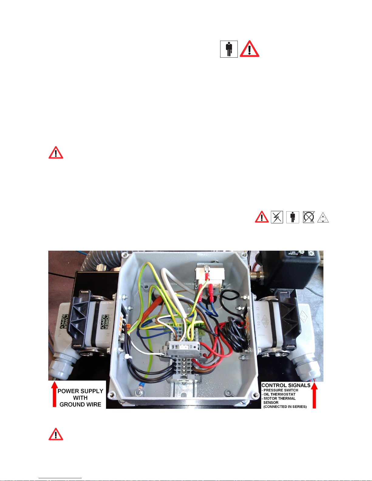
6.5.2 CONNECTING OF THE POWER CABLE OF COMPRESSOR
Plug the power cable through the cable gland and follow the path indicated by the red arrow as
shown in the figure below:
ATTENTION!
To connect the wires in the correct plug terminals, follow the electric scheme in
Cap. 8.1
Page 24
CONFIDENTIAL - This document is the property of K.T.C. S.r.l. and cannot be reproduced or issued to third parties without written
authorization. K.T.C. shall safeguard its rights to the full extent of the law.
USER MANUAL AND INSTALLATION
COD. 091052 - REV. 07 - DATE 11/2016
Pag.24 di 45
6.6 ELECTRICAL CONNECTION OF COMPRESSOR
The electrical connection to the electrical line is carried out by the end user. He bear
the costs and responsibility for quality and compliance standards, which must be
performed by trained personnel in accordance with accident prevention regulations
EN 60204.
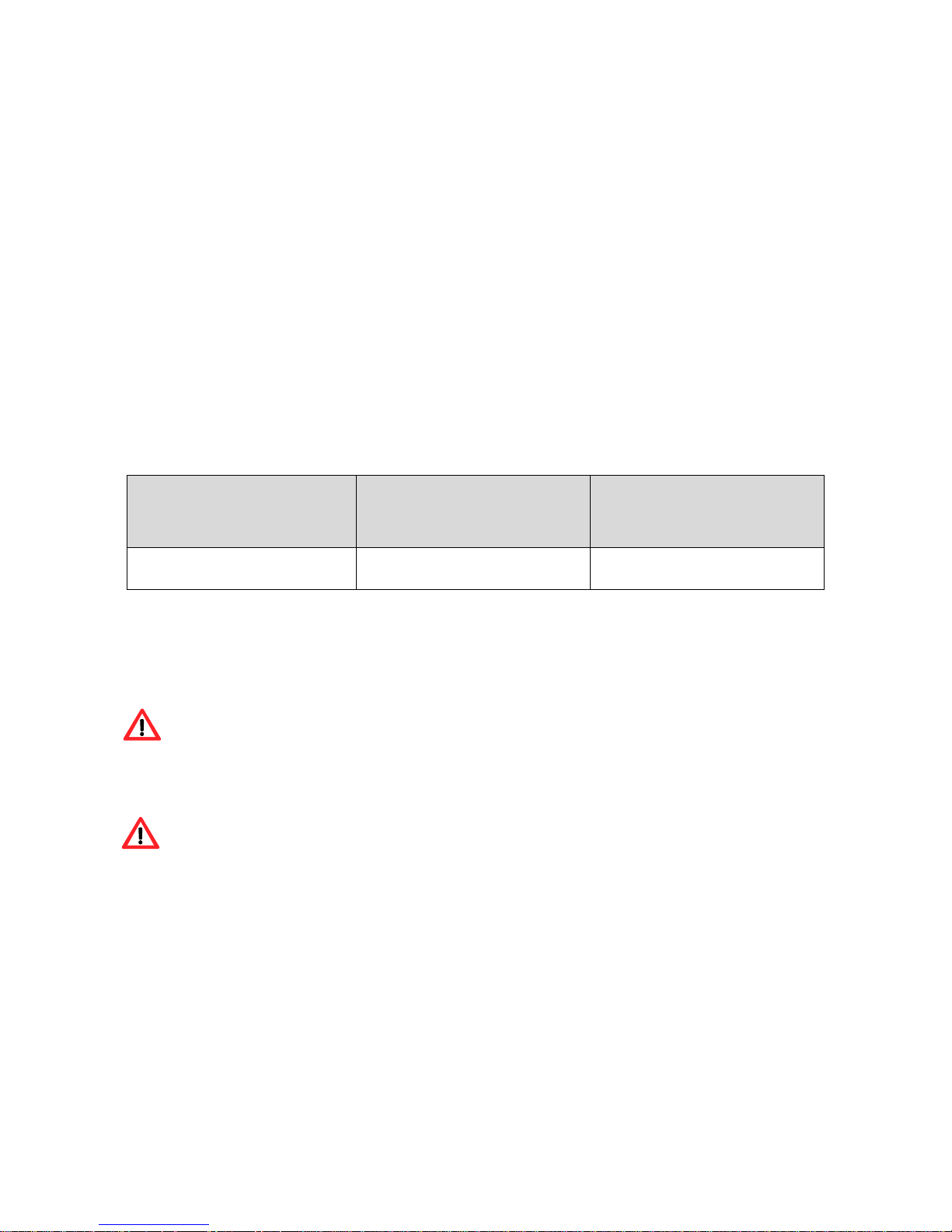
6.6.1 FUSE AND BREAKER
It is recommended to install the connector, the circuit breaker and fuses near the compressor
(not more than 3 meters). The circuit breaker and the fuses must have the characteristics shown
in the following table:
The voltage (volts) must correspond to that indicated on the nameplate of the electrical
machine; the tolerance must be within the + / -5%.
The plug of the power cable should not be used as a switch. Do not remove power while unit
is running; for emergency action to switch of the compressor or on the appropriate line
switch (breaker), see table.
Never use the ground instead of neutral. The ground connection must be made in
accordance with safety regulations (EN 60204). Verify that the mains voltage
corresponds to that required for the proper functioning of the compressor.
KW
Voltage
V230/3/50-60
Voltage
V400/3/50-60
Magnetothermic
Curve “ D “
3 poles **
Fuse with delay*
Magnetothermic
Curve “ D “
3 poles **
Fuse with delay*
3,0
16 A
12 aM
10 A
10 aM
* Raccomended type of fuse refer to class of use: gL/gG, aM
** Magnetotermic switch with “D“ curve, characteristics of adjustment according
to IEC 60 898 specific motors starter
Page 25
CONFIDENTIAL - This document is the property of K.T.C. S.r.l. and cannot be reproduced or issued to third parties without written
authorization. K.T.C. shall safeguard its rights to the full extent of the law.
USER MANUAL AND INSTALLATION
COD. 091052 - REV. 07 - DATE 11/2016
Pag.25 di 45
6.6.2 GROUND CONNECTION
The compressor must be connected to the ground during its use, in order to protect the operator
from accidental electric shocks. It 's necessary that the connections are made by a technician or an
authorized service center. The grounding conductor yellow / green wire of the power of the
compressor must only be connected to terminal of the compressor.
The ground wire connected to a facility must be properly equipped with mandatory safety switch.
6.6.3 SIZING OF ELECTRIC CABLE
Do not use a damaged cable but make sure it is in good condition. This section must be appropriate
to the current requested by the compressor. A little section of power cable can cause a voltage drop
with consequent loss of power and excessive heating of the cable itself, which can cause irreparable
consequences on the device supply. The cable section must be in proportion to its length. For
variations and modifications contact a qualified service center.
Avoid any risk of electric shock. Never use the compressor with a damaged power
cable. It is recommended to be checked periodically by a qualified power cords. Never
use the compressor in areas where they can be hazardous leakage current.
All electrical installations and maintenance on facility must be performed by a
qualified technician.
kW
230 V - 3 phase
50 Hz
400 V - 3 phase
50 Hz
3.0
2.5 mm²
1.5 mm²
Page 26

CONFIDENTIAL - This document is the property of K.T.C. S.r.l. and cannot be reproduced or issued to third parties without written
authorization. K.T.C. shall safeguard its rights to the full extent of the law.
USER MANUAL AND INSTALLATION
COD. 091052 - REV. 07 - DATE 11/2016
Pag.26 di 45
6.7 AIR CONNECTION OF COMPRESSOR
Be sure to use compressed air tubing with features and cross section appropriate to the
compressor. Do not repair a faulty tube, but proceed with the replacement.
Connect the compressor to the pneumatic network by using the special attack female 3/8" arranged
on the compressor and illustrated.
We recommend using a pipe with a diameter equal to or greater than the output of the compressor
3/8 ".
It is recommended during installation to connect a ball valve between the air tank and the line as
indicated above, (if not present in the supply).
Attention! The compressor does not require not-return valves because it is already
installed within. The valve mounting could cause incorrect operation of the
compressor.
Page 27

CONFIDENTIAL - This document is the property of K.T.C. S.r.l. and cannot be reproduced or issued to third parties without written
authorization. K.T.C. shall safeguard its rights to the full extent of the law.
USER MANUAL AND INSTALLATION
COD. 091052 - REV. 07 - DATE 11/2016
Pag.27 di 45
7 FIRST START
First start of compressor (operational test)
After following all steps of assembly of the compressor shown in Chapter 4, you can proceed with
the operation of preparing the compressor for the first start.
ATTENTION!
In this compressor is NOT PRESENT a control device that ensures the correct
rotation of the screw
.
If the supply phases are correctly positioned the compressor will start as indicated on the arrow on
the body of the screw as shown in Figure 10. (Check with motor fan)
If the phases of the supply line are positioned INCORRECTLY, the inverse rotation
will damage the airend.
Swap the connections of two phases of power line and restart the compressor.
Figure 10
ATTENTION!
The reverse rotation of the screw from the direction of the arrow shown on the body
(see figure 10) may damage the screw!
ATTENTION!
In case of replacement of the electric motor, at the time of restart is absolutely
necessary to visually check the direction of rotation of the screw unit.
ATTENTION!
It's absolutely necessary to strictly follow the SAFETY PRECAUTIONS on the use
of the machine.
Page 28

CONFIDENTIAL - This document is the property of K.T.C. S.r.l. and cannot be reproduced or issued to third parties without written
authorization. K.T.C. shall safeguard its rights to the full extent of the law.
USER MANUAL AND INSTALLATION
COD. 091052 - REV. 07 - DATE 11/2016
Pag.28 di 45
8 CONTROL PANEL
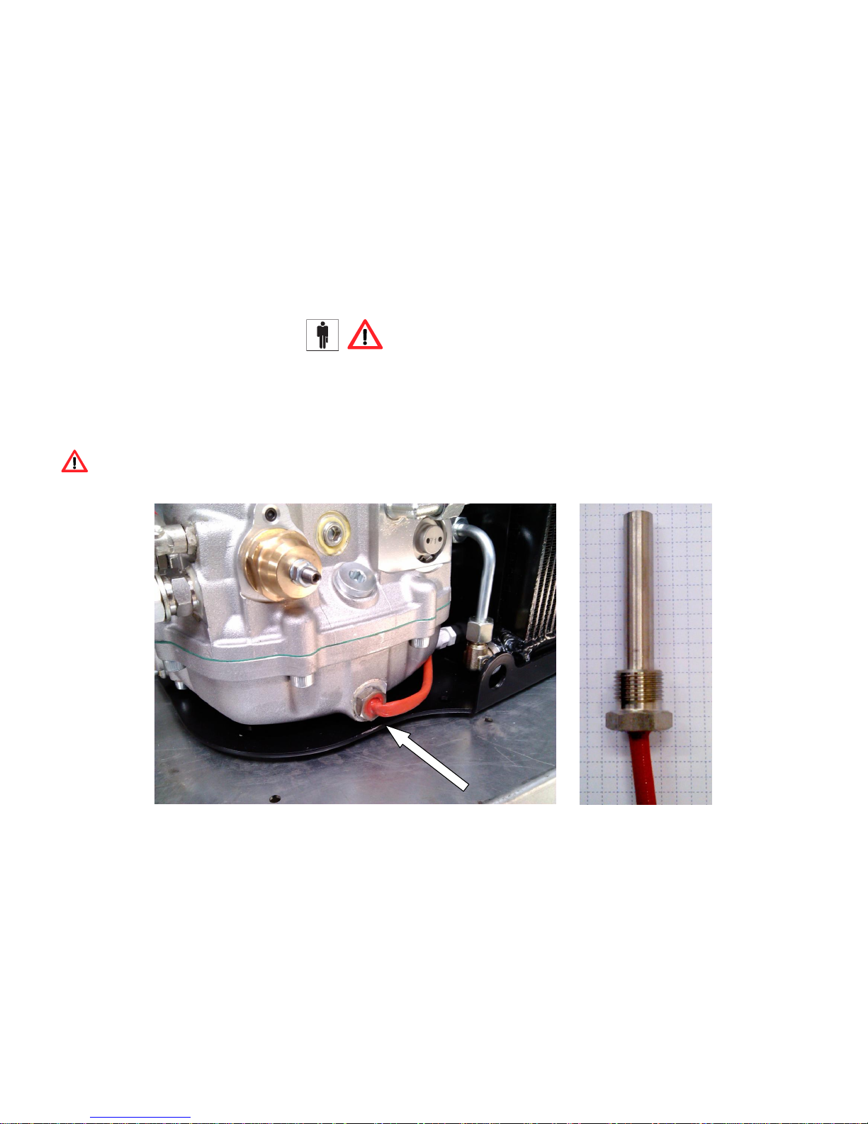
ATTENTION!
The manual control of the compressor (on / off) can be managed only by the switch
placed over the pressure switch and in case of arrest for excessive temperature can
be reset by pressing the reset button of the thermostat (see the picture below). Any
other control will be managed by the final user (via controller or inverter) which
shall be solely responsible. How to manage the various controls, refer to the wiring
diagram.
ATTENTION!
After an emergency stop at high temperature release the line switch.
Reset the thermostat, unscrewing the cap hexagon and pressing the button inside.
Page 29

CONFIDENTIAL - This document is the property of K.T.C. S.r.l. and cannot be reproduced or issued to third parties without written authorization. K.T.C. shall safeguard its rights to the full extent of the law.
USER MANUAL AND INSTALLATION
COD. 091052 - REV. 07 - DATE 11/2016
Pag.29 di 45
8.1 ELECTRIC DIAGRAM
Page 30

CONFIDENTIAL - This document is the property of K.T.C. S.r.l. and cannot be reproduced or issued to third parties without written authorization. K.T.C. shall safeguard its rights to the full extent of the law.
USER MANUAL AND INSTALLATION
COD. 091052 - REV. 07 - DATE 11/2016
Pag.30 di 45
Page 31

CONFIDENTIAL - This document is the property of K.T.C. S.r.l. and cannot be reproduced or issued to third parties without written authorization. K.T.C. shall safeguard its rights to the full extent of the law.
USER MANUAL AND INSTALLATION
COD. 091052 - REV. 07 - DATE 11/2016
Pag.31 di 45
Page 32

CONFIDENTIAL - This document is the property of K.T.C. S.r.l. and cannot be reproduced or issued to third parties without written authorization. K.T.C.
shall safeguard its rights to the full extent of the law.
USER MANUAL AND INSTALLATION
COD. 091052 - REV. 07 - DATE 11/2016
Pag.32 di 45
Heavy duty POWER and CONTROLLER connectors with spring terminal connectors
Inserts for section conductors: 0.14 - 2.5 mm2
- AWG 26 – 14
conductors stripping lenght: 9...11 mm
Necessary Tool: 0.5x3.5mm Flat screwdriver
1)Insert the flat
screwdriver
3)Insert the wire
conductor, then remove
the screwdrive
2)Push the
screwdriveng to
open up the spring
connector
4)Check the wire conductor
is correct fixed
Page 33
CONFIDENTIAL - This document is the property of K.T.C. S.r.l. and cannot be reproduced or issued to third parties without written authorization. K.T.C. shall safeguard its rights to the full extent of the law.
USER MANUAL AND INSTALLATION
COD. 091052 - REV. 07 - DATE 11/2016
Pag.33 di 45
9 HEATING RESISTANCE of OIL
ATTENTION!
In the compressor is installed a heating resistance, which has the function of maintaining the oil of the compressor at a temperature of about
50-60 °C even when this is not in operation so as to avoid formation of water condensation inside the air/oil separator tank.
For electrical characteristics see the ch. 2
IMPORTANT!
So it is essential that this resistance is fed even when the compressor is not in operation, in each case after 2 or 3 days of stationary car
is advisable to disconnect this power in such a way as to prevent the batteries from discharging.
Page 34

CONFIDENTIAL - This document is the property of K.T.C. S.r.l. and cannot be reproduced or issued to third parties without written authorization. K.T.C. shall safeguard its rights to the full extent of the law.
USER MANUAL AND INSTALLATION
COD. 091052 - REV. 07 - DATE 11/2016
Pag.34 di 45
10 PNEUMATIC SCHEME AND MACHINE DESCRIPTION
1- Intake valve
2- Screw compressor
3- Air tank
4- Solenoid valve 3/2
5- Safety valve
6- Manometer
7- Oil cooler
9- Minimum pressure valve
11- Pressure switch
12- Oil return from air/oil
separator
13- Separator filter
15- Air/oil separator tank
16- Air filter
17- Oil filter
22- Oil recovery viewer
25- Thermostatic valve
26- Electric cooling fan
29- Electric motor
30- Oil level
31- Oil discharge
Page 35
CONFIDENTIAL - This document is the property of K.T.C. S.r.l. and cannot be reproduced or issued to third parties without written
authorization. K.T.C. shall safeguard its rights to the full extent of the law.
USER MANUAL AND INSTALLATION
COD. 091052 - REV. 07 - DATE 11/2016
Pag.35 di 45
11 ORDINARY MAINTENANCE OF COMPRESSOR
The following table is a plan for maintenance of the compressor.
The work hours listed in the table refer to the optimal use of the machine and can therefore vary
depending on the working environment and the number of cycles.
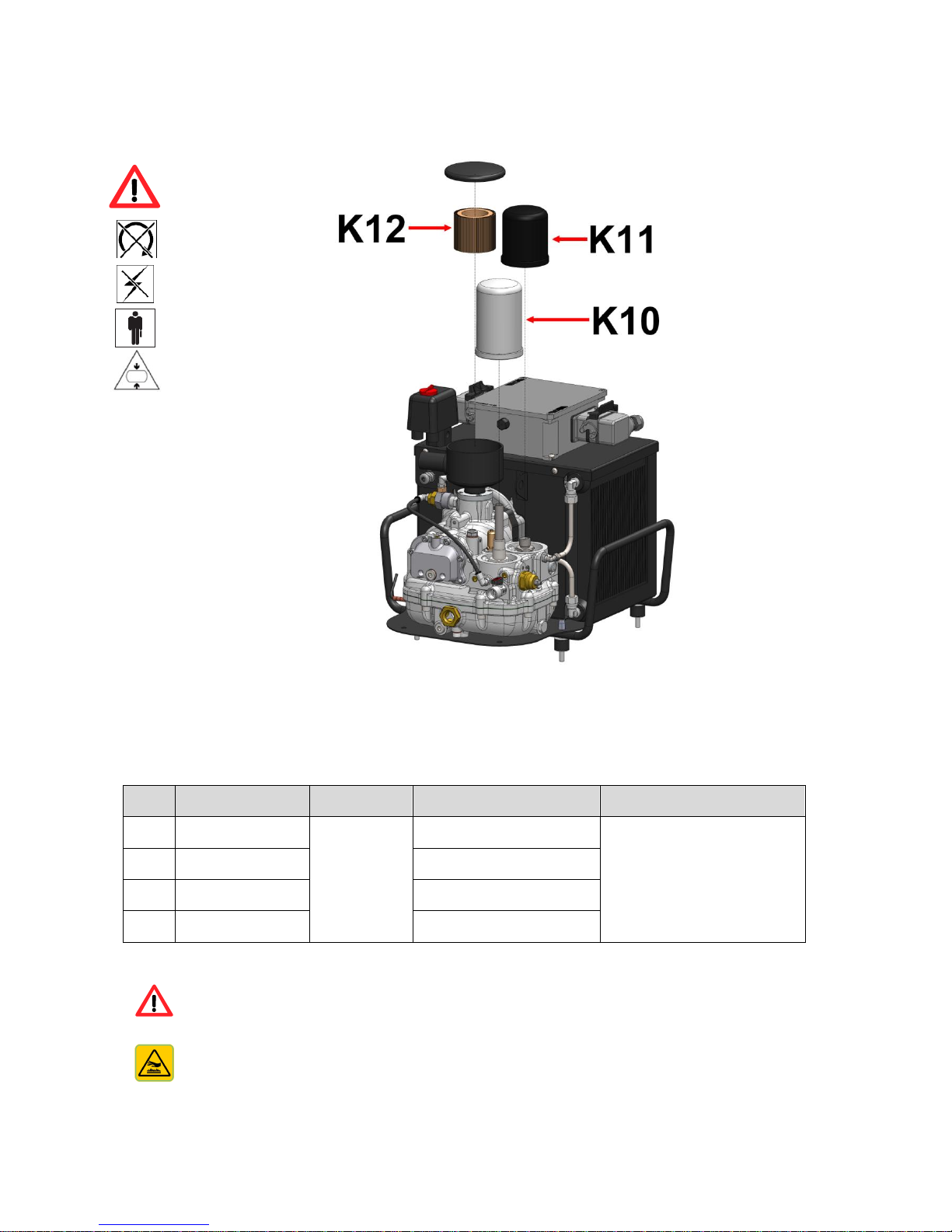
ATTENTION: USE ONLY GENUIINE PARTS!!!
ATTENTION: HOT PARTS INSIDE!!!
MACHINE
CODE
DESCRIPTION
HOURS OF WORK
COMPACK 2
N11L0119
OIL CHANGE
every 1000 hours
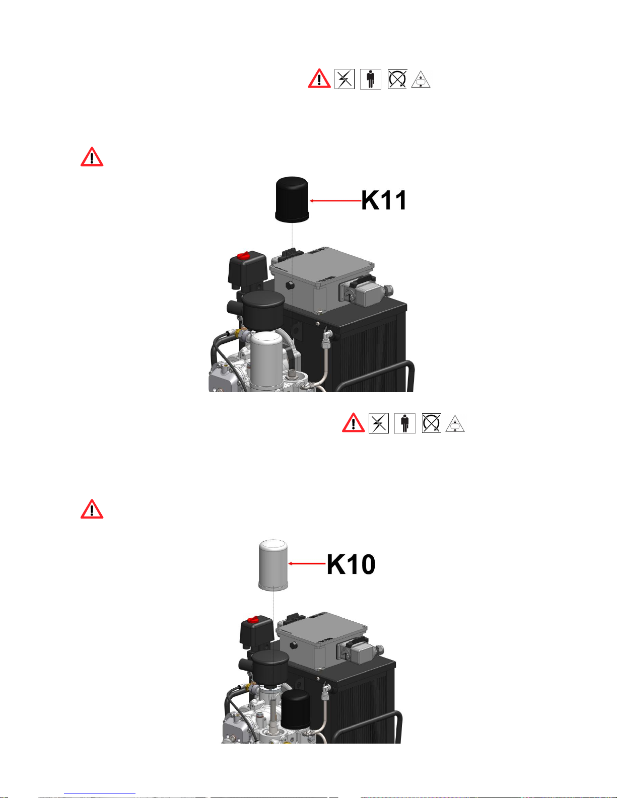
K10
COMPACK 2
De-oiler cartridge
K11
COMPACK 2
Oil filter cartridge
K12
COMPACK 2
Air filter cartridge
Page 36

CONFIDENTIAL - This document is the property of K.T.C. S.r.l. and cannot be reproduced or issued to third parties without written
authorization. K.T.C. shall safeguard its rights to the full extent of the law.
USER MANUAL AND INSTALLATION
COD. 091052 - REV. 07 - DATE 11/2016
Pag.36 di 45
EVERY LEVEL CONTROL AND POSSIBLE OIL TOPPING OFF THE MUST BE
MADE WITH MACHINE STOPPED AND SYSTEM DEPRESSURIZED.
WASTE LUBRICANT MUST BE DISPOSED IN ACCORDANCE WITH THE
REGULATIONS.
FOR HEAVY ENVIRONMENTAL CONDITIONS (ex. ESPECIALLY DUSTY
PLACES) THE MAINTENANCE SCHEDULE WILL BE MORE CLOSE.
CONSULT AN AUTHORIZED SERVICE CENTER.
THE NON COMPLIANCE OF THE TIMES OF MAINTENANCE OF OIL
FILTERS, AIR FILTERS AND SEPARATOR FILTERS MAY CAUSE DAMAGE
TO THE COMPRESSOR.
IT IS ABSOLUTELY ESSENTIAL TO FOLLOW CAREFULLY THE
INSTRUCTIONS ON THE USE OF SAFETY TO USE PROPERLY THE
MACHINE.
MAINTENANCE MUST BE EXERCISED BY EXPERTS. IN ANY CASE TO
FOLLOW SAFETY RULES APPLICABLE (USE APPROPRIATE SAFETY).
Page 37
CONFIDENTIAL - This document is the property of K.T.C. S.r.l. and cannot be reproduced or issued to third parties without written
authorization. K.T.C. shall safeguard its rights to the full extent of the law.
USER MANUAL AND INSTALLATION
COD. 091052 - REV. 07 - DATE 11/2016
Pag.37 di 45
11.1 REPLACEMENT OF OIL FILTER
Unscrew with a specific tool (chain or belt) to replace the cartridge filter, lubricate the gasket of the
new cartridge before attaching the support, the mounting is done by hand, after tightening the
cartridge and placed on the base just 'around ½ ensure the seal.
Be careful before you screw the filter cartridge oil the seal.
Hand tighten the new filter cartridge.
11.2 REPLACEMENT OF SEPARATOR FILTRE
Remove with a specific tool (chain or belt) to replace the cartridge filter, lubricate the gasket of the
new cartridge before attaching the support, the mounting is done by hand, after tightening the
cartridge and placed on the base just 'around ½ ensure the seal.
Be careful before you screw the filter cartridge oil the seal.
Hand tighten the new filter cartridge.
Page 38
CONFIDENTIAL - This document is the property of K.T.C. S.r.l. and cannot be reproduced or issued to third parties without written
authorization. K.T.C. shall safeguard its rights to the full extent of the law.
USER MANUAL AND INSTALLATION
COD. 091052 - REV. 07 - DATE 11/2016
Pag.38 di 45
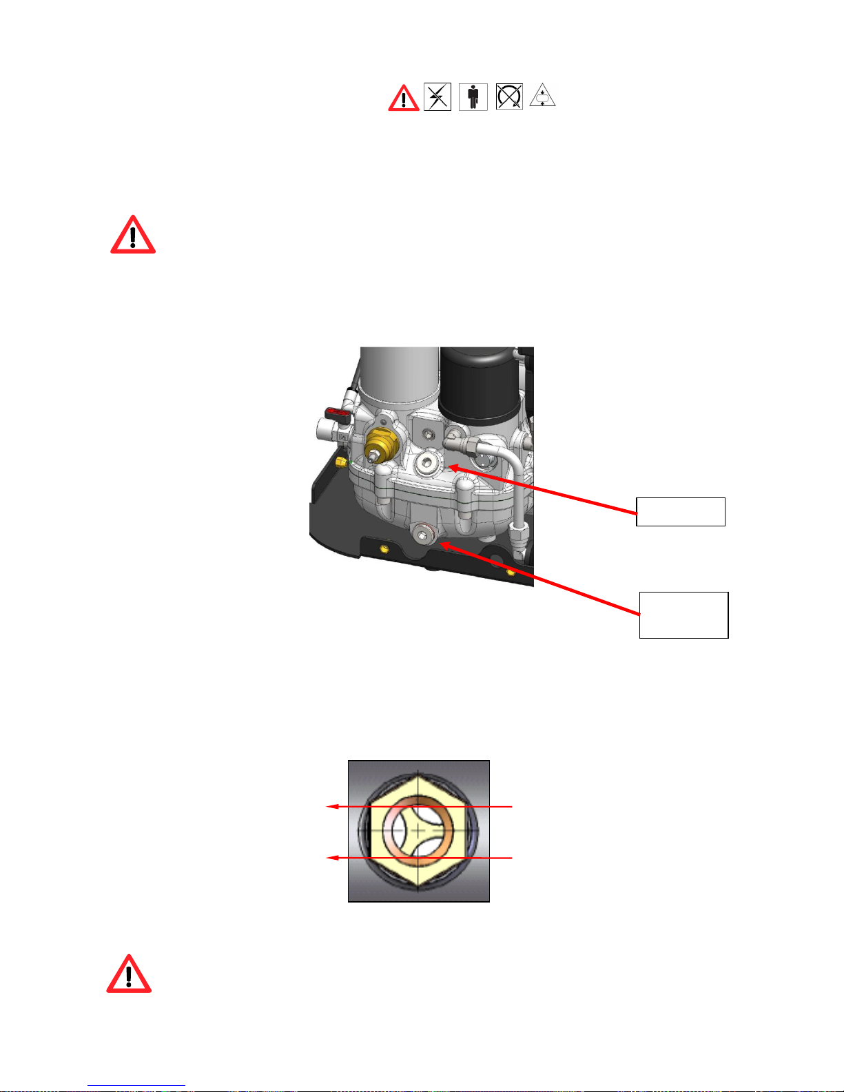
11.3 CHANGING OIL
Change the oil as indicated in the table on cap 9.1 extending the number of hours before
replacement depends on the type of oil used but in no case can oil be used for more than one year.
If the compressor is not used frequently (a couple of hours a day), we recommend changing the oil
every 6 months and periodically opening the oil drain ball valve to check for condensation residues.
When the oil drain ball valve is opened, oil starts flowing out of the screw assembly.
Always keep on all necessary equipment to collect the oil.
Open filling cap.
Open emptying cap.
Once emptied, close the emptying cap.
Then top up the oil until the right level is read on the window (see figure 12). Then tighten the oil
filling cap once more.
After having replaced the oil and oil filter, run the compressor for about 10 minutes, turn it off and
check the oil level. If necessary, top up.
MAX OIL LEVEL
MIN OIL LEVEL
Figure 13
Never mix different types of oil. Make certain that the oil circuit is completely empty
before performing any maintenance. Always replace the filter at each oil change.
Filling cap
Emptying
cap
Page 39

CONFIDENTIAL - This document is the property of K.T.C. S.r.l. and cannot be reproduced or issued to third parties without written
authorization. K.T.C. shall safeguard its rights to the full extent of the law.
USER MANUAL AND INSTALLATION
COD. 091052 - REV. 07 - DATE 11/2016
Pag.39 di 45
11.4 REPLACEMENT OF AIR FILTER
Renew the air filter cartridge every 1000 hours a year of work. Unscrew the top cover and replace
the filter cartridge.
The duration of the air filter and proportionate to the type of environment and contamination by
dust.
If you are heavily contaminated environments, it is necessary to reduce the period to replace the air
filter.
Page 40

CONFIDENTIAL - This document is the property of K.T.C. S.r.l. and cannot be reproduced or issued to third parties without written
authorization. K.T.C. shall safeguard its rights to the full extent of the law.
USER MANUAL AND INSTALLATION
COD. 091052 - REV. 07 - DATE 11/2016
Pag.40 di 45
12 MAINTENANCE SCHEDULE
Codice/Code
Modello/Type
MOTOR
ORE/HOURS
Contenuto / Content
LISTINO/LIST
N11L0119
COMPACK 2
trifase/3ph
400/50/3
1000
- Filtro Aria / Air Filter
- Filtro Olio / Oli Filter
- Filtro Separatore / Separator
Filter
- Olio / Oil
€ 140
N11L0284
2000
- Filtro Aria / Air Filter
- Filtro Olio / Oli Filter
- Filtro Separatore / Separator
Filter
- Olio / Oil
- Anello elastico trasmissione
/Elastic ring of trasmission
€ 160
N11L0285
8000
- Filtro Aria / Air Filter
- Filtro Olio / Oli Filter
- Filtro Separatore / Separator
Filter
- Olio / Oil
- Anello elastico trasmissione
/Elastic ring of trasmission
- Valvola minima
pressione/Minimum pressure
valve
- Valvola
termostatica/Thermostatic
valve
- Valvola di aspirazione/Inlet
valve
- Cuscinetto MOTORE/Motor
bearing
- Kit paraolio PackSmart/
PackSamrt shaft seal KIT
€ 340
N11L0286
20000
- Filtro Aria / Air Filter
- Filtro Olio / Oli Filter
- Filtro Separatore / Separator
Filter
- Olio / Oil
- Anello elastico trasmissione
/Elastic ring of trasmission
- Kit paraolio PackSmart/
PackSamrt shaft seal KIT
- Kit ricambio cuscinetti
PackSmart/ PackSmart bearing
€ 470
Page 41

CONFIDENTIAL - This document is the property of K.T.C. S.r.l. and cannot be reproduced or issued to third parties without written
authorization. K.T.C. shall safeguard its rights to the full extent of the law.
USER MANUAL AND INSTALLATION
COD. 091052 - REV. 07 - DATE 11/2016
Pag.41 di 45
The maintenance program is set considering all installation and operating parameters recommended
by the Manufacturer.
The Manufacturer recommends keeping a log of the maintenance works performed on the
compressor.
The table indicates working hours for a standard machine. These working hours can be modified
depending on work environment and cycle numbers.
Page 42

CONFIDENTIAL - This document is the property of K.T.C. S.r.l. and cannot be reproduced or issued to third parties without written
authorization. K.T.C. shall safeguard its rights to the full extent of the law.
USER MANUAL AND INSTALLATION
COD. 091052 - REV. 07 - DATE 11/2016
Pag.42 di 45
13 TROUBLESHOOTING
Problem
Cause
Resolution
Stop machine for
oil thermostat
intervention
Excessive temperature of air/oil
mixture exiting the screw
(max 105°C)
- Check the oil level
- Check the clean of cooler.
- Check when the machine is running if the fan
works
To restart the machine must be switched off
and press the reset thermostat button located
under the cover of the thermostat.
If the arrest due to high temperature persists,
contact the service center.
Stop machine
intervention thermal
compressor motor
- Switch 0/1 on the pressure
switch unarmed and
compressor is stopped.
- High temperature of motor.
- High power consumption.
- If the intervention happens when the
compressor is on, check that the phases are
stable.
- If it happens when the compressor is
running, make sure the internal pressure of
the group and replace the separator
cartridge.
- If the motor draws a current higher than the
rated current, contact an authorized service
technician.
Do not insist too much with the starts
because they could cause serious damage
to the electrical plant of compressor
Opening safety
valve
Pressure switch doesn’t work and
the pressure exceeds the value
set by the safety valve.
- Remove the cover and check if the pressure
switch has traces of oxide or dirt. If there
are, remove them with a mild antioxidant
- Intake valve does not close, check that it is
locked.
The compressor runs
but the pressure
remains low
- The intake valve does not
open
- Loss of air that prevents the
increase pressure
- Coupling screw-engine to check
- When the machine is off and depressurized
safely, remove the air filter and check if the
shutter moves
- Check if there are leaks from the pipes that
disperse the air produced.
- Check carefully if the motor runs but does
not transmit the motion to the screw.
Contact a service center
Leakage of oil from
the air filter.
- The oil level is too high
- Oil recovery viewer dirty
- Separator Cartridge
exhausted
- Remove excess oil with the machine
stopped and checking the oil sight glass.
- Remove the oil recovery viewer and clean it.
If necessary replace it.
- Replace the air/oil separator cartridge,
making sure to clean his nipple
Safety valve group
vented air
compressor is
running.
- The pressure has exceeded the
limit of opening of the safety
valve.
- The separator cartridge air / oil
filter is clogged.
- Replace the safety valve.
- Replace the air/oil separator cartridge
- Contact an authorized service centre
Page 43

CONFIDENTIAL - This document is the property of K.T.C. S.r.l. and cannot be reproduced or issued to third parties without written
authorization. K.T.C. shall safeguard its rights to the full extent of the law.
USER MANUAL AND INSTALLATION
COD. 091052 - REV. 07 - DATE 11/2016
Pag.43 di 45
Problem
Cause
Resolution
Motor thermal
sensor causes
machine to stop.
Main motor
overloaded.
Low line voltage.
Phase missing.
High oil separator pressure.
Make certain that electric power supply is
correct.
Check that the 3 power phases are at
approximately the same value and that the
cables are firmly secured to the terminal.
Check that the cables are not damaged.
Make certain the main motor ventilation is
free of any fouling or foreign objects.
If the motor is running in two phases, have
it checked by a qualified technician. If
necessary, have the motor repaired or
replaced.
The oil separator differential pressure is
above 1.0 bar causing high system
absorption. Have the unit checked by
qualified personnel.
Environmental temperature too high: air
the room.
To start up the machine again, reset it
using the special button on the control
panel.
When starting up the
unit for the first time,
the machine does not
start. Phase anomaly
alarm.
The line phases are not
correct.
Invert two power supply phases on the main
switch. (only for 3 phases version)
CAUTION!! UNPLUG THE MACHINE.
Excessive oil
consumption.
Oil not suitable for the
compressor operation.
Air-oil separator cartridge
spent or defective.
Oil recovery viewer clogged.
Oil level too high.
Replace oil, fill machine with the oil
indicated by the manufacturer. Replace oil
separator cartridge. Clean or replace oil
recovery window.
Top up oil until it reaches the level indicated
in the manual.
Page 44

CONFIDENTIAL - This document is the property of K.T.C. S.r.l. and cannot be reproduced or issued to third parties without written
authorization. K.T.C. shall safeguard its rights to the full extent of the law.
USER MANUAL AND INSTALLATION
COD. 091052 - REV. 07 - DATE 11/2016
Pag.44 di 45
14 APPENDIX
14.1 MAINTENANCE CONTROL BOARD
Page 45

CONFIDENTIAL - This document is the property of K.T.C. S.r.l. and cannot be reproduced or issued to third parties without written
authorization. K.T.C. shall safeguard its rights to the full extent of the law.
USER MANUAL AND INSTALLATION
COD. 091052 - REV. 07 - DATE 11/2016
Pag.45 di 45
15 COMMERCIAL PARTS, SPARE PARTS AND RELATED
DOCUMENTATION
For further information please consult the web site www.ktc-air.com
For further information please contact customer service or your local dealer.
ATTENTION!
Do not touch the moving parts when the compressor is running.
All maintenance of the compressor must be carried off (pressure and temperature) and
circuit switched off.
Maintenance must be performed by qualified personnel. Always follow the safety rules in
force (use appropriate safeguards).
We reserve the right to make changes to this manual, in our discretion and without notice.
The manufacturer disclaims any liability for personal injury, property damage caused by
incorrect operation of the compressor unit, failure or superficial compliance with security
policies in this document, by even slight changes, from tampering and the use of spare parts
are not original.
 Loading...