

KSR Moto GRS125 2013 User Manual
mod.#
USER MANUAL
U 14 168/2013
ENG

1
INTRODUCTION
Thanks for your purchasing of this vehicle. This model is designed for safety, built for durability, and
perfected for daily street use. The unique vehicle design, enrich of stylish and personality, represents your
outstanding taste and favor to pursue the state of the art living attitude.
This manual describes the correct usage of this motorcycle including safety riding, simple inspection methods
and so on. For a more comfortable and safety riding, please read this manual carefully . If any questions concerning
the operation or maintenance of your vehicle, please consult a dealer.
2
IMPORTANT MANUAL INFORMATION
In this manual with some important information is distinguished by the following notations:
!
WARNING
Is a WARNING which has to be followed. Refusing to follow can lead to
severe injury or death to the operator.
CAUTION
A CAUTION indicates a important information to avoid damage to the vehicle.
CAUTION
• Please always put this manual with vehicle for rider maintenance/ dealer tracking of service records even if vehicle is
being sold.
• This manual contains the most of the vehicle information, however, the maker will continually improve it’s product
design and quality that lead to difference between the manual and vehicle . If you have any questions concerning this
manual, please consult your dealer.
!
WARNING
FOR YOUR OWN SAFETY, PLEASE READ THIS MANUAL CAREFULLY BEFORE OPERATION THIS VEHICLE. ONLY OPERATE THE VEHICLE UNTIL YOU HAVE COMPLETELY AWARE OF ADEQUATE KNOWLEDGE OF CONTROLS AND OPERATION
FEATURE AND YOU HAVE BEEN TRAINED IN SAFE AND PROPER RIDING TECHNIQUES. PERIODIC INSPECTIONS, WELL
MAINTENANCE AND GOOD RIDING SKILLS, WILL ENSURE YOUR SAFETY RIDING AND INCEASE THE PRODUCT RELIABILITY OF THIS VEHICLE.
*Product and specications are subject to change without notice.

3
IMPORTANT MANUAL INFORMATION
Dealer label here

4
TABLE OF CONTENTS
INTRODUCTION 1
IMPORTANT MANUAL INFORMATION
2
TABLE OF CONTENTS
4
SAFETY INFORMATION
6
Safe riding 6
Protective clothing 6
Modications 7
Loading and accessories 7
Accessorries 7
Gasoline and exhaust gas 8
Other safe-riding points 8
DESCRIPTION OF THE VEHICLE
9
Side view 9
Controls and instruments 10
CONSUMER INFORMATION
11
Vehicle identikation number (VIN) 11
INSTRUMENT AND CONTROL FUNCTIONS
12
Main switch 12
Dashboard unit 13
Handlebar switches - Left 14
Handlebar switches - Right 14
Brake lever 15
Brake pedal 15
Gear shift pedal 15
Fuel tank 16
Remove the fuel tank cap 16
Install the fuel tank cap 16
Fuel 16
Catalytic converter 17
Seat 17
Open the seat 17
Close the seat (2) 17
Side stand 18
Main stand 18
Combined brake system (CBS) 18
PRE-OPERATION CHECKS
19
Pre-operation check list 20
OPERATION AND IMPORTANT RIDING
POINTS
21
Starting the engine 21
Starting off 21
Shifting and riding 21
Acceleration / Deceleration 22
Braking 22
Stop the Engine / Parking 22
Engine break in 23
PERIODIC MAINTENANCE AND MINOR
REPAIR
24
Owner’s tool kit 24
Spark plug 24
Check the spark plug
24
Engine oil
26
Check engine oil 26
Oil change
26
Fuel lter
27
Air lter
27
ECU 27
Idling speed 27
Throttle cable free play 27
Throttle cable free play adjustment 27
Clutch free play 28
Clutch free play adjustment 28
Tires 28
Tire air pressure 28
Tire inspection 29
Rims 30
Brake free play 30
Front brake 30
Rear brake 30
Brake padel free play 30
Brake pads 31
Brake uid 31
Changing the brake uid 32
Cables 32
Throttle grip and cable 32
Lubricating the brake lever and brake
pedal 32
Side stand 32
Front fork 32
Steering 33
Wheel bearings 33
Drive chain 34
Tensioning the chain drive 34
Shock absorber 34
Adjust the shock absorber 34
Charge the battery 35

5
TABLE OF CONTENTS
Store the battery 35
Fuse 35
Replacing the fuse 35
Lighting 36
Headlight 36
Position light 36
Front turn signal light 36
Rear turn signal light 36
Taillight / Brake light lamp 36
License plate lamp 36
TROUBLESHOOTING
37
Troubleshooting chart 37
CLEAN AND STORAGE
39
Clean the vehicle 39
Before cleaning 39
Cleaning after normal use 39
Cleaning after riding in the rain, near
the sea or on salt-sprayed roads 39
After cleaning 40
Storage 40
Short-term (for a few days) 40
Long-term (for weeks) 40
SPECIFICATIONS
42
WARRANTY INFORMATION
45
SERVICE AND MAINTENANCE
46
Important information 46
Maintenance schedule 47
Service record 48
SPACE FOR NOTES 49

6
SAFETY INFORMATION
THIS VEHICLE ARE TWO WHEEL
SINGLE TRACK VEHICLES. THE
USE OF SAVETY AND OPERATION MAY IN DIFFERENT RESULT
BY THE USE OF PROPER RIDING
TECHNIQUES OF THE OPERATOR.
TO REMIND OF OPERATOR, WHO
SHOULD KNOW THE FOLLOWING
REQUIREMENTS BEFORE RIDING.
HE OR SHE SHOULD:
• WELL TRAINED AND FIMILIAR
TO ALL THE ASPECTS OF Vehicle
OPERATION.
• FULLY READ AND AWARE OF
MAINTENANCE REQUIREMENTS
THAT NOTED IN THIS OWNER’S
MANUAL.
• OBTAIN QUALIFIED TRAINING &
LEGAL LICENSE FOR OPERATION OF THIS VEHICLE.
• WELL AND PROFESSIONAL
MAINTENANCE SERVICE FOR
OPERATOR AND CERTIFICATED REPAIR SHOP/DEALER TO
ACQUIRE GOOD MECHANICAL
CONDITIONS OF VEHICLE.
Safe riding
• Always pre-check your vehicle before riding is important to prevent an
accident.
• Please follow the maximum loads limited of operator and passenger.
• Many accidents happening to motorists are caused by car drivers who
fail to recognize them. Therefore, to
make yourself conspicuous to trafc
will be very effective to reducing the
change of this kind of accidents.
Therefore:
• Wear bright colored and protective
clothes.
• Operate the turning signals before
turning and slow down the speed
when approaching and passthrough
the intersection
• Keep proper distance to other Motorists, and let them be aware of your
location
• Know your skills and limits
• Never lend your vehicle to others
who are not qualied for riding
• Always follow the legal speed limits
on the vehicle and trafc law.
• The posture of the operator and
passenger is important for proper
control. A proper riding posture can
Keep vehicle in balance while riding.
• Operator should sit up-right with two
hands on the handle bar and both
feet on the footpegs while driving.
• The passenger should make sure
that he/she can rmly hold the grip
or the operator with feet on the footpegs.
• Driving after consuming alcohol or
illegal drugs is strickly prohibited.
• This vehicle is designed for onroad
use only. It is not suitable for off-road
use.
Protective clothing
Properly clothing will keep you safe
from potential accidents:
• Always wear an approved helmet
with face shield to protect your eye
from dust and rain drop.
• The wear of a proper jacket, shoes,
gloves etc., provides better protec-
tion, reducing the degree of injuiry

7
SAFETY INFORMATION
from unexpected accidents.
• Never wear loose clothes, otherwise
they could catch on the control le-
vers or wheels and cause injury or
an accident.
• Never touch the engine or exhaust
system during or after operation.
They become very hot and can
cause burns. Always wear protective
clothing that cover your legs, ankles,
and feet.
Modications
Modications made to this vehicle
which are not approved by the maker,
or the removal of original equipment,
may make the vehicle unsafe for use
and can cause severe personal injury.
Modications may also make your ve-
hicle illegal to use.
Loading and accessories
Adding accessories or cargo to your
vehicle will cause a different weight
distribution of the vehicle and inuence
the steering & balance.
It may cause
the possibility of an accident.
Be extremely cautious and follow the
limitation below when equipped with
accessories / cargo. Below are some
guidelines to follow if loading cargo or
adding accessories to your vehicle.
Loading
The total weight of the operator, pas-
senger (when allowed), accessories
and cargo must not exceed the maximum load limit.
Maximum load
(not include the vehicle):
150kg
When loading within this weight limit,
keep following points in mind:
• Cargo and accessory weight should
be kept as low and close to the vehicle as possible. Make sure to distribute the weight as evenly as possible on both sides of the vehicle to
minimize imbalance or instability.
• Make sure that accessories and cargo are securely attached to vehicle
before riding
• Never attach any large or heavy
items to the handlebar, front fork, or
front fender. Such items can create
unstable handling or a slow steering
response.
Accessorries
Genuine accessories have been speci-
cally designed for use on this vehicle.
If need, please contact with dealer for
detail. Since the maker can not test all
other accessories, you are personally
responble for the proper selection, installation and use of non OEM accessories.
Keep the following guidelines in mind,
when mounting accessories.
• Never install accessories or carry
cargo that would inuence on the
ground clearance, limit suspension
travel, steering, or obscure lights or
turning lights, reectors.
• Accessories on the handle bar/front
suspension area will cause bad inuence on steering the vehicle. if you

8
SAFETY INFORMATION
will install accessories, please keep
it as light in weight and not interfere
on steering the vehicle.
This vehicle
is for On-Road transportation purpose only, please do not install any of
extended cargo carrier as sulky, that
will make vehicle unstable in cross
winds and vehicle turns.
• While equipped with electrical ac-
cessories, please consult qualiled
stores, to make sure such items
will not exceed the capacity of the
vehicle’s electrical system. Unproper installation of such items may
cause a dangerous loss of lights, lower engine power or even damage
the vehicle.
Gasoline and exhaust gas
GASOLINE IS HIGHLY FLAMMABLE:
• Always turn the engine off when
refueling.
• Take care not to spill any gasoli-
ne on the engine (hot) or exhaust
system when refueling.
• Do not smoke or use Mobile pho-
ne while re-fueling.
• Never start the engine or let it run for
any length of time in a closed area.
The exhaust fumes are poisonous
and may cause loss of consciousness and death within a short time.
• Always turn the engine off before
leaving the vehicle and remove the
key from the main switch. When parking the vehicle, please note the following:
• The engine and exhaust system
remain hot, therefore, park the vehicle in a place where pedestrians
or children are not likely to touch
these hot areas.
• Do not park the vehicle on a slope
or soft ground, otherwise it may
fall over.
• Do not lay your vehicle to near
ammable place.
• In case of swallow any gasoline, or
gasoline get into your eyes, please
see your doctor immediately. Keep
away the gasoline to your skin and
water.
OTHER SAFE-RIDING POINTS
• Turn the signal before making turns.
• When raining or across on run on
the wet road, Iron Plates, keep your
speed low, slightly using braking to
avoid slipping or even fall down.
• Be careful when passing parked
cars. A driver might not see you and
open a door in your path.
9
DESCRIPTION OF THE VEHICLE
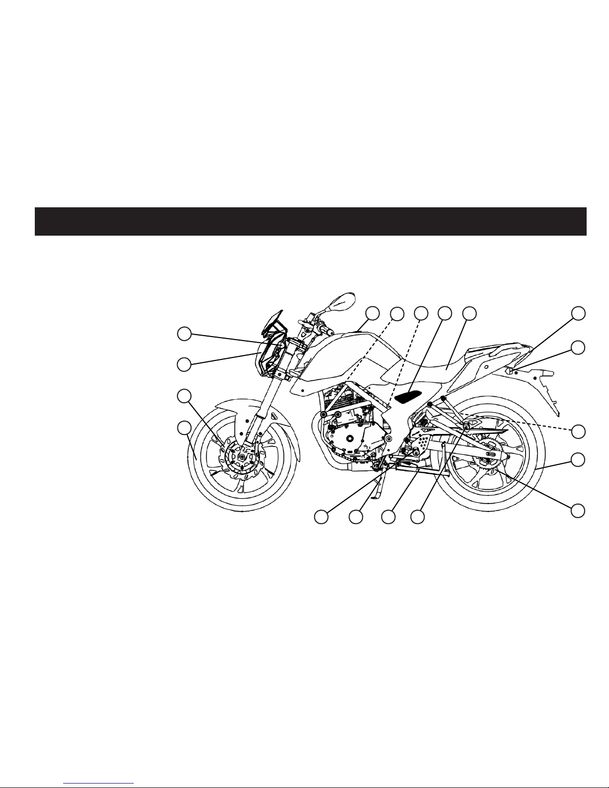
SIDE VIEW
1. Wheel - Front
2. Brake disc - Front
3. Headlight
4. Turn signal light - Front
5. Fuel tank cap
6. Spark plug
7. Air lter
8. Battery
9. Seat
10. Tail light / Brake light
11. Turn signal light - Rear
12. Mufer
13. Wheel - Rear
14. Brake disc - Rear
15. Footpeg passenger
16. Main stand
17. Side stand
18. Footpeg
1
5
10
13
14
1617 1518
7
6
2
4
12
3
8
11
9
10
DESCRIPTION OF THE VEHICLE
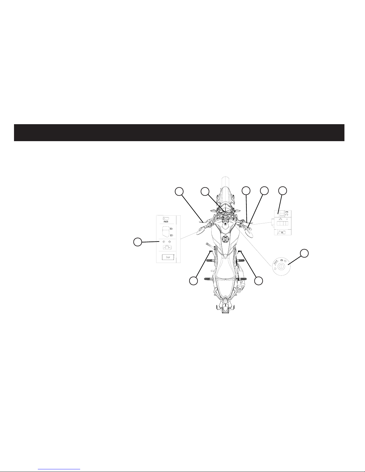
CONTROLS AND INSTRUMENTS
1. Handlebar switches - Left
2. Clutch lever
3. Dashboard unit
4. Brake lever - Front brake
5. Throttle grip
6. Handlebar switches - Right
7. Main switch
8. Brake pedal - Rear brake
9. Shift pedal
2
7
3
64 5
1
9 8

11
CONSUMER INFORMATION
VEHICLE IDENTIFIKATION NUMBER (VIN)
Please write down the VIN (vehicle identication number) to order replacement parts from your dealer or the vehicle should
be stolen.
The vehicle identication number of the vehicle (1) is stamped on the steering head (right).
1
CAUTION
The vehicle identication number is used to identify your motorcycle and may be used to register your vehicle with the
licensing authority in your area.
12
INSTRUMENT AND CONTROL FUNCTIONS
MAIN SWITCH
The main switch controls the ignition
and lighting systems, and also used to
lock the steering. The various positions
are described as below.
On
All electrical circuits are supplied with
power, the engine can be started. The
key cannot be removed.
Off
All electrical systems are off . The key
can be removed.
Steering lock
The steering is locked, and all electrical systems are off. The key can be
removed.
Lock the steering
1. Turn the handlebar fully to the left.
2. Insert the key into the main switch.
3. Turn the key while you apply pressure to it, counterclockwise in the
position. If the lock does not engage
immediately, move the handlebars
back and forth slightly.
4. Remove the key.
Unlock the steering
1. Insert the key into the main switch.
2. Turn the key clockwise to the position. If the lock does not engage
immediately, move the handlebars
back and forth slightly.
!
WARNING
Never turn the key to or , while
the vehicle is moving, otherwise the
electrical systems will be switched
off, which may result in loss of control or an accident. Make sure that
the vehicle is stopped before turning the key.
13
INSTRUMENT AND CONTROL FUNCTIONS
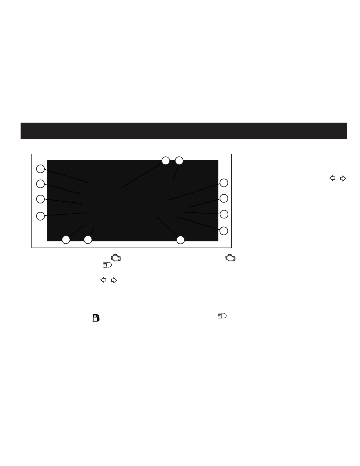
DASHBOARD UNIT
1. Engine warning light (EOBD)
2. High beam indicator lamp
3. Neutral indicator lamp N
4. Turn signal indicator light /
5. Rev counter
6. Speedometer
7. Gear indicator
8. Odometer
9. Fuel warning indicator
10. Clock
11. Function button 1
12. Function button 2
1. Engine warning light (EOBD)
When you turn on the ignition, the lamp
lights up. After starting the engine, it
disappears. If your vehicle detects a
failure in the system, the check engine lamp lights up. Contact a dealer to
check with a diagnosis tool.
2. High beam indicator lamp
Lights up whenever high beam is switched on.
3. Neutral indicator lamp (N)
Lights up whenever neutral (N) is selected.
4. Turn signal indicator light /
This indicator light ashes when the
turn signal light is activated.
5. Rev counter
Displays the engine speed in RPM.
6. Speedometer
The dashboard unit is equipped with a
speedometer. The speedometer shows
the riding speed.
7. Gear indicator
Indicates which gear is currently enga-
ged. In neutral (N), no light is lit.
8. Odometer
The dashboard unit is equipped with an
odometer. The odometer shows the total distance traveled.
1112
1
2
3
4
564
7
8
9
10
14
INSTRUMENT AND CONTROL FUNCTIONS
9. Fuel warning indicator
The fuel warning indicator shows if you
have little fuel left in the tank. Refuel
immediately.
The fuel gauge indicates the amount of
fuel in the fuel tank. The needle moves
towards „E“ (Empty) as the fuel level
decreases.
CAUTION
Be take care not let the fuel tank to fully
empty it-self, that cause engine can not
run it-self anymore.
10. Clock
Displays the time of day.
11. Function button 1
When you press this button you can
shift from total meter to trip meter.
12. Function button 2
When you press this button you can
shift from km to mile.
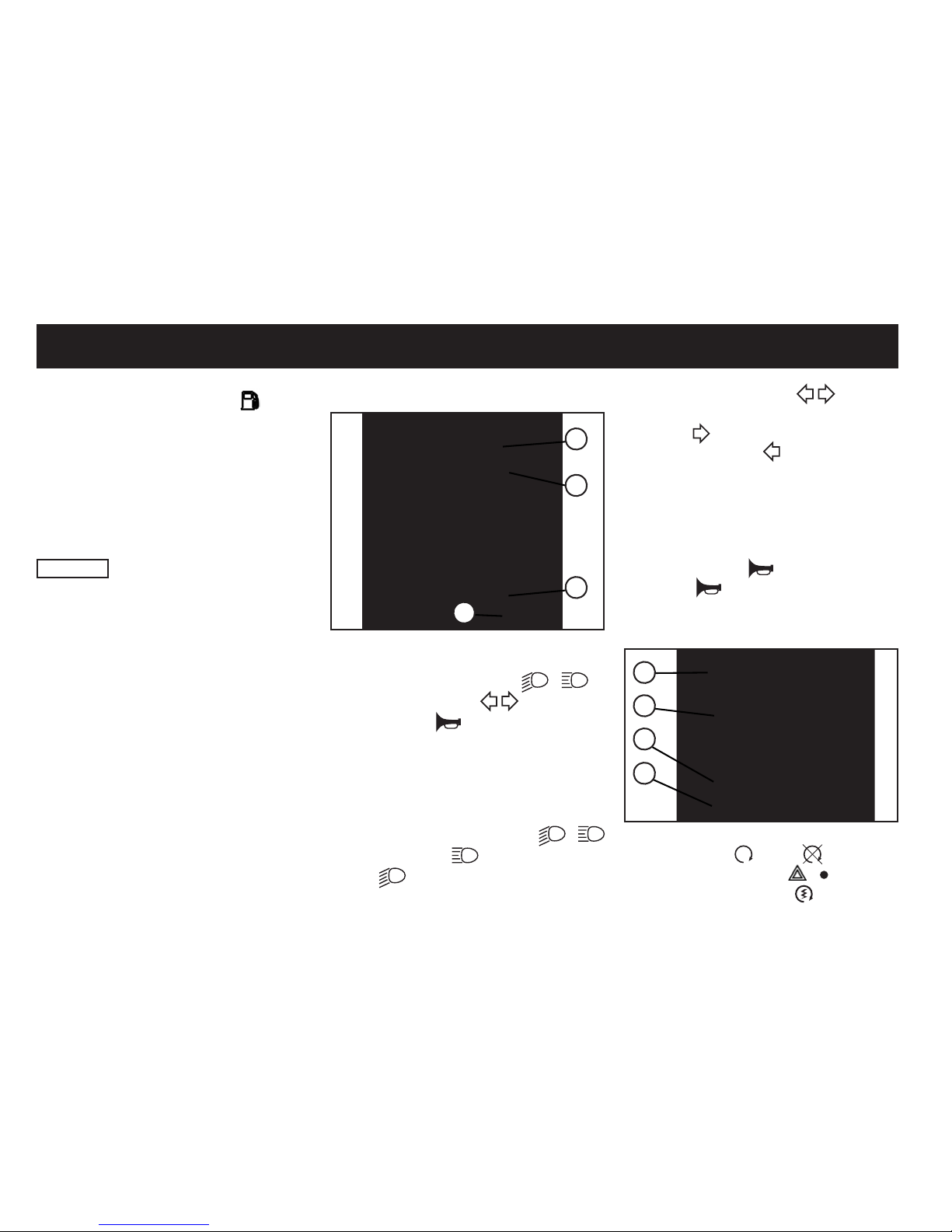
HANDLEBAR SWITCHES - LEFT
1
2
3
4
1. Passing beam switch
2. High / Low beam switch /
3. Turn signal switch
4. Horn switch
1. Passing beam switch
As long as the button is pressed will
light the high beam.
2. High / Low bean switch /
Set this switch to for the high beam
and to for the low beam.
3. Turn signal switch
To signal a right-hand turn, push this
switch to . To signal a left-hand turn,
push this switch to . When released
the switch returns to the center position. To cancel the turn signal lights,
push the switch in after it has returned
to the center position.
4. Horn switch
Press this switch to sound the horn.
HANDLEBAR SWITCHES - RIGHT
3
4
1
2
1. Lever adjustment
2. Engine - ON / OFF
3. Warning light switch /
4. Electro starter switch
15
INSTRUMENT AND CONTROL FUNCTIONS
1. Lever adjustment
You can adjust the lever distance to
suit your needs. Push the lever forward
slightly and turn the screw in the desired positions of the four, this must be
on the lever opposite the arrow symbol.
Position 1 is the longest, position 4 is
the shortest.
2. Engine - ON / OFF
The power switch is “ON” and ignition
switch is at position, at the meantime, grip the brake, the engine can be
started. And press engine off switch at
position, the engine is will be off.
3. Warning light switch /
By changing the switch position you
can switch on or off the warning
light.
4. Electro start switch
Push this switch (pull the brake lever at same time) to the start the en-
gine.
CAUTION
Before starting the vehicle check the
notes in the user manual.
BRAKE LEVER
The front brake lever is located on the
right handlebar grip. To apply the front
brake, pull this lever toward the handlebar grip.
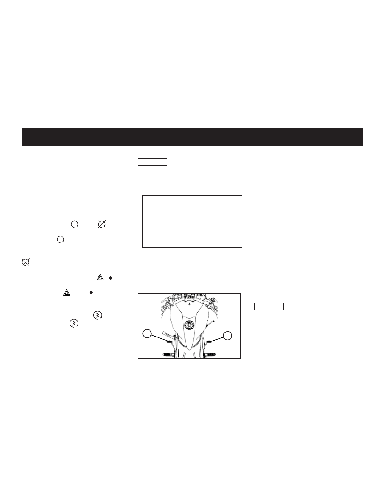
BRAKE PEDAL
1
2
The brake pedal (1) is located on the
right-hand side of the vehicle and operates the rear brake. Familiarise yourself with how it works before you ride
the vehicle on public roads. Novices
and returning riders are recommended
to take a riding techniques course.
GEAR SHIFT PEDAL
The gear shift pedal (2) is located on
the left side of the vehicle.
The vehicle is equipped with a 5-speed
manual transmission.
Before commissioning, familiarize
yourself with the handling of such a
transmission, otherwise serious dama-
ge and or injuries could be provoked.
CAUTION
Never attempt to change gear without
releasing the clutch. Novices and returning riders are recommended to take a
riding techniques course.
 Loading...