


Installation and
Operating Instructions
Please retain for future usage
120873 / Rev. 01 – 07.05.2015
Float Switches
S12... / S14... / S18...
INTRODUCTION
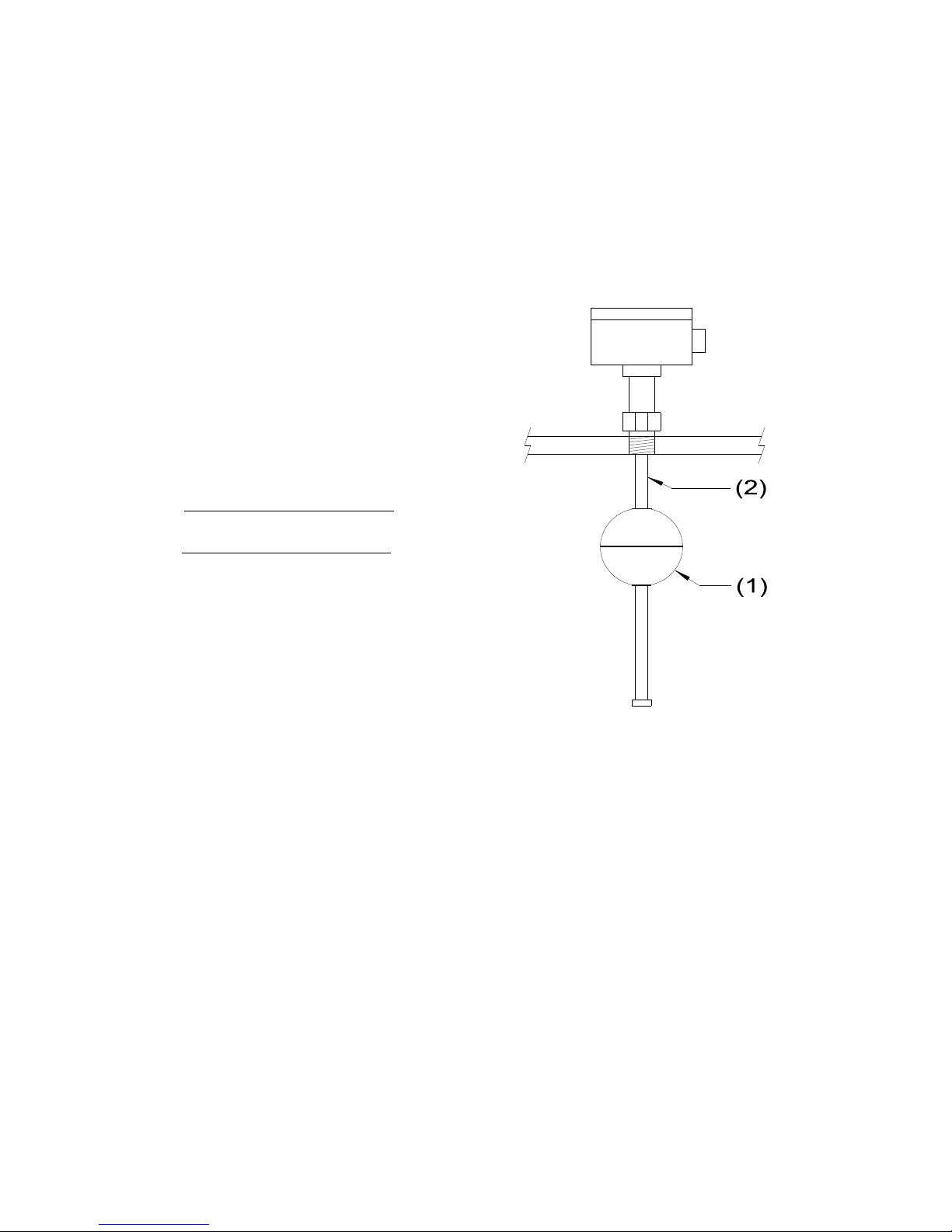
KSR Kuebler float switches are primarily used for remote point measurement of liquid levels.
They operate by using the field of a magnet inside the float (1) to actuate reed switches inside the
device rod (2). The overall length, switch positions, and number of floats are customer specified at
the time of order. Float switches are SPDT and can be configured for different functions at the
time of installation.
For your convenience please enter:
Model #
Serial #
KSR Kuebler float switches have approvals for Explosion Proof Class 1, Division 1, Group B
depending on the ordered configuration. All materials which come into contact with the liquid
must be corrosion resistant and are customer specified. The liquid to be monitored must not be
heavily contaminated and must not have a tendency to crystallize or solidify.
KSR Kuebler float switches must be installed within 30 degrees of vertical to function
correctly. They must not be installed within 3 feet of strong electromagnetic fields.
When installing a float switch in a vessel connection smaller than the diameter of the
float requiring removal of the float(s), mark the top of the float(s) and the position of
the retaining collar(s). Be sure to replace the float(s) in the same orientation.
Reposition and securely tighten the retaining collar(s).
INSTALLATION NOTES!
(TOP SWITCH)
010-0102-XXX REV A
010-0101-XXX REV A
All wiring and hardware must be in accordance with applicable standards and
regulations. Inductive loads must have a RC network (AC circuits) or recovery diode
(DC circuits) and capacitive loads must have a series resistor to prevent early failure of
the switch contacts. KSR Kuebler float switches are designed for pilot service or
connection to a PLC. They should not be used to directly switch heavy loads as contact
damage resulting in failure can occur.
Install a pour-seal (conduit seal) fitting within 18 inches of the housing to prevent water
from entering the housing and for compliance with the National Electrical Code.
INSTALLATION
Install KSR float switches according to their type (flange or thread) using the correct gasket or
compound for sealing. Make sure the gasket is installed correctly and tighten all fasteners to the
correct torque. Replace the float(s) and retaining collar(s) in the correct orientation if previously
removed.
Wire sizing must be determined by the run length with a maximum size of 14 AWG. A ground
wire must be provided and connected to the ground block inside the housing.
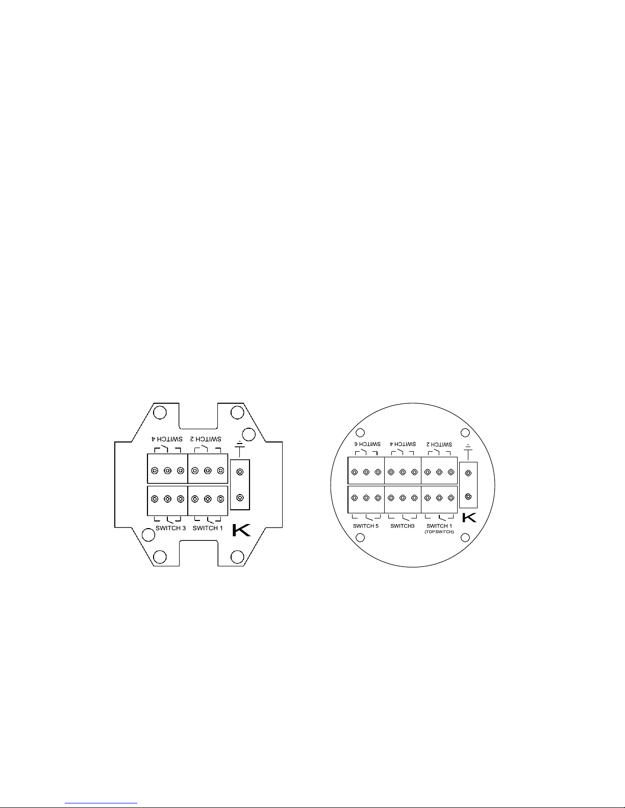
1 to 4 switch PCB 5 and 6 switch PCB
The symbols screened on the terminal block board show the connections to the terminal blocks
(Figure 1). Note that the upper switch in the device rod (nearest the flange) is numbered switch 1
and labeled “top switch” on the pc board. All other switches count consecutively downward.

Normally Closed Common Normally Open
Figure 1
Figure 1 defines the contact positions when the float is not actuating the switch.
Connect each conductor to the appropriate terminal and tighten securely. For AC inductive loads
connect an appropriate RC network (snubber) across the load. For DC inductive loads connect a
recovery diode across the load (Figure 2).
SWITCH
AC
LOAD
R
C
RC Network Recovery Diode
+
DC
-
LOAD
SWITCH
Figure 2
For capacitive loads, wiring greater than 150 feet, or connection to a PLC with capacitive input
circuitry, connect a series resistor to limit current spikes (Fig. 3).
R
Figure 3
Warning! Overloading float switches can cause premature failure, malfunctions in control circuitry,
and damage or injury to persons or property. The maximum switch capacity specified for the
switch contacts (see “Specifications” section) must not be exceeded.

QUALIFICATION
WARNING! Make sure any tests performed in qualification do not unintentionally start or
stop any processes resulting in loss of control.
WARNING! Never open cover in hazardous areas while circuits are energized. Follow all
safety work procedures and lock out circuits before servicing or inspection.
Replace and tighten the housing and energize the power supply for the connected control unit(s).
Fill the tank in order to observe that the switch points and switch functions are as designed. The
float switch can also be tested manually by moving the float by hand and observing the result. The
switch points are measured from the face of the flange or NPT threads and are printed on the label
located on the housing. Check that the switches operate at these distances.
MAINTENANCE
KSR Kuebler float switches operate free from maintenance and wear when used properly. A
periodic visual inspection and re-qualification test should be performed at regular intervals.
SPECIFICATIONS
Float Switch Type S8
Switch Type: SPDT
Max. Voltage: 250 VAC, VDC
Max. Current: 0.5 A AC, 0.25 A DC
Max. Power: 10 VA, 0.7 p.f. / 5 Watts
Float Switch Type S12, S18, S48, SS12, SS18, SP12, SP20, F50, F70
Switch Type: SPDT
Max. Voltage: 250 VAC, VDC
Max. Current: 1 A AC, 0.5 A DC
Max. Power: 40 VA, 0.7 p.f. / 20 Watts
QUESTIONS?
For customer support please call 1-888-KSR-LEVL (577-5385) between the hours of 8:00 a.m. and
5:00 p.m. Eastern time. Please have your model number and serial number (found on the device
label) handy.

KSR Kuebler Limited
Product Warranty
When used in accordance with the applicable documentation, all KSR Kuebler level controls are warranted free of
defects in workmanship or materials to the original end-user as follows from the date of original factory shipment:
Five (5) full years for Level Switches & Magnetic Level Indicators
Two (2) full years for Level Transmitters
When returned prepaid within the warranty period and upon factory inspection of the unit and verification of a defect,
KSR Kuebler will repair or replace, at its discretion, the defective unit at no cost (other than transportation). KSR
Kuebler shall not be liable for direct or consequential equipment damage due to corrosion nor any incompatibility of
the materials of construction of the equipment with the process and/or equipment of the user. KSR Kuebler shall not
be liable for any type of damage, or loss, direct or consequential, due to misapplication, mis-specification, misuse,
damage due to mechanical or electrical overloading, improper mounting, or failure of the device. KSR Kuebler shall
not be liable for any direct or consequential damage, expense, or labor claims stemming from the use or installation of
KSR Kuebler equipment. Any unauthorized modification, repair or rework of KSR Kuebler equipment renders this
warranty null and void.
THE WARRANTIES SET FORTH ABOVE ARE EXCLUSIVE AND IN LIEU OF ALL OTHER
WARRANTIES, WHETHER STATUTORY, EXPRESS OR IMPLIED (INCLUDING ALL WARRANTIES OF
MERCHANTABILITY AND FITNESS FOR A PARTICULAR PURPOSE AND ALL WARRANTIES ARISING
FROM COURSE OF DEALING OR USAGE OF TRADE).

NOTES

KSR Kuebler of America Inc
950 Hall Court
Deer Park, Texas 77536
Phone: 713-475-0022
Fax: 713-475-0011
info@ksr-usa.com
www.ksr-usa.com
KSR Kuebler Niveau-Messtechnik AG
Heinrich-Kuebler-Platz 1
69439 Zwingenberg am Neckar
Phone: +49 6263 87-0
Fax: +49 6263 87-99
info@ksr-kuebler.com
www.ksr-kuebler.com
 Loading...