

KS Motorcycles K-LIGHT125 Maintenance Manual

Maintenance Manual of
Two-wheeled Motorcycle
(K-LIGHT125)
KS MOTORCYCLES - https://ksmotorcycles.com

Contents
Contents ................................................................................................................................................................. - 1 -
Preface ................................................................................................................................................................... - 4 -
Preparatory information ......................................................................................................................................... - 5 -
General safety ................................................................................................................................................ - 5 -
Maintenance rules .......................................................................................................................................... - 6 -
Motorcycle identification ............................................................................................................................. - 10 -
Important notes ............................................................................................................................................ - 11 -
Special tools ................................................................................................................................................. - 11 -
Specification table ........................................................................................................................................ - 18 -
Fa
ult diagnosis ............................................................................................................................................. - 20 -
Inspection / adjustment ................................................................................................................................ - 47 -
Inspection and Maintenance of Electrical System ............................................................................................... - 72 -
I. Battery/Charging System.................................................................................................................................. - 74 -
1.1 Preparatory Information ......................................................................................................................... - 74 -
1.2 Fault Diagnosis ...................................................................................................................................... - 75 -
1.3 Battery ................................................................................................................................................... - 76 -
1.4 Charging System .................................................................................................................................... - 77 -
1.5 Disassembly of Voltage and Current Regulator ..................................................................................... - 78 -
1.6 Alternator Charging Coil ....................................................................................................................... - 79 -
1.7 Disassembly of Alternator ..................................................................................................................... - 79 -
II. Ignition System ............................................................................................................................................... - 83 -
2.1 Pr
eparatory Information ......................................................................................................................... - 83 -
2.2 Fault Diagnosis ...................................................................................................................................... - 85 -
2.3 Trigger ................................................................................................................................................... - 86 -
2.4 Igni
tion Coil ........................................................................................................................................... - 86 -
2.5 Spark Plug .............................................................................................................................................. - 88 -
2.6 ECU ....................................................................................................................................................... - 88 -
III. Starter System ................................................................................................................................................ - 90 -
3.1 Pr
eparatory Information ......................................................................................................................... - 90 -
3.2 Fault Diagnosis ...................................................................................................................................... - 91 -
3.3 Starter Motor .......................................................................................................................................... - 91 -
3.4 Starter Relay .......................................................................................................................................... - 92 -
IV. Bulbs /Switches/Meters ................................................................................................................................. - 95 -
4.1 Pr
eparatory Information ......................................................................................................................... - 95 -
4.2 Fault Diagnosis ...................................................................................................................................... - 96 -
4.3 Replacement of Headlight Bulb ............................................................................................................. - 97 -
4.4 Replacement of Front Turn Signal Light Bulb ...................................................................................... - 98 -
4.5 Replacement of Taillight Bulb ............................................................................................................... - 98 -
4.6 Replacement of License Light Bulb ...................................................................................................... - 99 -
4.7 Meters .................................................................................................................................................... - 99 -
4.8 Ignition Switch..................................................................................................................................... - 100 -
- 1 -
KS MOTORCYCLES - https://ksmotorcycles.com

4.9 Electric horn ........................................................................................................................................ - 102 -
4.10 Handlebar Switch ............................................................................................................................... - 104 -
Inspection and Maintenance of Chassis ............................................................................................................. - 105 -
V. Brake ............................................................................................................................................................. - 108 -
5.1 Preparatory Information ....................................................................................................................... - 108 -
5.2 Fault Diagnosis .................................................................................................................................... - 109 -
5.3 Front Brake Disc .................................................................................................................................. - 109 -
5.4 Rear Brake Disc ................................................................................................................................... - 111 -
5.5 CBS ...................................................................................................................................................... - 113 -
VII. Front Wheel/Front Suspension ................................................................................................................... - 134 -
7.1 Preparatory Information ....................................................................................................................... - 134 -
7.2 Fault Diagnosis .................................................................................................................................... - 135 -
7.3 Front Wheel ......................................................................................................................................... - 135 -
7.4 Handlebar ............................................................................................................................................. - 140 -
7.5 Front Fork ............................................................................................................................................ - 145 -
7.6 Front Shock Absorber .......................................................................................................................... - 151 -
VIII. Rear wheel/rear suspension ...................................................................................................................... - 160 -
8.1 Preparation of Information- ................................................................................................................. - 160 -
8.2 Fault Diagnosis .................................................................................................................................... - 160 -
8.3 Rear wheel ........................................................................................................................................... - 161 -
8.4 Rear shock absorber ............................................................................................................................. - 166 -
8.5 Rear Rocker Arm ................................................................................................................................. - 168 -
8.6 Chain drive .......................................................................................................................................... - 171 -
IX. Fuel Tank/Seat ............................................................................................................................................. - 180 -
9.1 Preparatory information ................................
....................................................................................... - 180 -
9.2 Fault Diagnosis .................................................................................................................................... - 180 -
9.3 Seat ...................................................................................................................................................... - 181 -
9.4 Fuel T ank ............................................................................................................................................. - 182 -
X. Disassembly/Installation of Engine .............................................................................................................. - 190 -
10.1 Preparatory information ..................................................................................................................... - 190 -
10.2 Fault Diagnosis .................................................................................................................................. - 190 -
10.3 Disassembly of Engine ...................................................................................................................... - 191 -
10.4 Installation of Engine ......................................................................................................................... - 191 -
Inspection and maintenance of engine ............................................................................................................... - 193 -
XI. Lubrication System ...................................................................................................................................... - 195 -
11.1 Preparatory Inform ati on ..................................................................................................................... - 195 -
11.2 Fault Diagnosis .................................................................................................................................. - 195 -
11.3 Fuel Pump .......................................................................................................................................... - 196 -
XII. Cylinder head / valve ................................................................................................................................. - 201 -
12.1 Preparatory information ..................................................................................................................... - 201 -
12.2 Fault Diagnosis .................................................................................................................................. - 202 -
12.3 Cylinder Head .................................................................................................................................... - 202 -
12.4 Valve inspection ................................................................................................................................. - 206 -
12.5 Replacement of Valve Guide ............................................................................................................. - 207 -
12.6 Finishing Valve Seat Ring .................................................................................................................. - 208 -
- 2 -
KS MOTORCYCLES - https://ksmotorcycles.com

12.7 Installation of Cylinder Head ............................................................................................................. - 209 -
XIII. Cylinder Block and Piston ........................................................................................................................ - 211 -
13.1 Pr
eparatory Information ..................................................................................................................... - 211 -
13.2 Fault Diagnosis ............................................................................................................................... - 212 -
3.3 Cylinder Block ..................................................................................................................................... - 213 -
13.4 Piston ................................................................................................................................................. - 214 -
13.5 Installation of Cylinder Block ............................................................................................................ - 218 -
XIV. Clutch / kickstarter mechanism .............................................................................................................. - 221 -
14.1 Preparatory Information ..................................................................................................................... - 221 -
14.2 Fault Diagnosis .................................................................................................................................. - 221 -
14.3 Clutch ................................................................................................................................................. - 222 -
14.4 Kickstarter Mechanism ...................................................................................................................... - 224 -
14.5 Disassembly of primary and auxiliary shafts ..................................................................................... - 225 -
XV. Variable speed gear ..................................................................................................................................... - 229 -
15.1 Pr
eparatory Information ..................................................................................................................... - 229 -
15.2 Fault Diagnosis .................................................................................................................................. - 229 -
15.3 Shift mechanism ................................................................................................................................ - 230 -
15.4 Installation ......................................................................................................................................... - 233 -
XVI. Crankcase ................................................................................................................................................. - 235 -
16.1 Preparatory Information ..................................................................................................................... - 235 -
16.2 Fault Diagnosis .................................................................................................................................. - 235 -
16.3 Crankcase ........................................................................................................................................... - 236 -
16.4 Crankshaft combination ..................................................................................................................... - 239 -
XVII. Exhaust Emission Control System .......................................................................................................... - 246 -
17.1 G
uarantee of Exhaust Emission Control System ............................................................................... - 246 -
17.2 Re
gular Maintenance Notice ............................................................................................................. - 246 -
17.3 Mechanical Function of Exhaust Control System ............................................................................. - 247 -
17.4 Catalyst Conversion System .............................................................................................................. - 247 -
XVIII. Electronic Injection System ................................................................................................................... - 251 -
18.1 Int
roduction of Electronic Injection System ...................................................................................... - 251 -
18.2 EFI Parts ............................................................................................................................................ - 252 -
18.3 Fault Maintenance and Diagnosis Method ........................................................................................ - 268 -
18.4 Common Troubleshooti ng Methods .................................................................................................. - 271 -
Circuit Diagram................................................................................................................................................ 277
- 3 -
KS MOTORCYCLES - https://ksmotorcycles.com

Preface
This Maintenance Manual is the explanation for the maintenance essentials of
dealers.
Pr
eparatory information includes all matters needing attention for operation in
the Maintena nce Manual. Please read this Manual carefully be fore operation.
Inspection and adjustment is the explanation for the essentials of inspection and
adjustment, as well as the safety of motorcycles and performance maintenance
methods of parts, which shou ld be implement ed from the time of regular inspection.
Chapter II and subsequent chapters are the explanations for the decomposition,
combination and inspection of the others of electrical equipment, motorcycle and
engine.
Exploded diagrams and system diagrams, maintenance fault diagnosis and
instructions are provided above all chapters.
Note:
The style or structure of the motorcycle and the photographs, pictures or
instructions on the Manual are subject to change without further notice.
- 4 -
KS MOTORCYCLES - https://ksmotorcycles.com

Preparatory information
General safety
Special tools
Maintenance rules
Specification table
Motorcycle identification
Fault diagnosis
Important notes
General safety
Carbon monoxide
If the engine must be started, ensure that the workplace is well-ventilated and do not operate the engine in a closed
place.
Notes
Exhaust gas contains
carbon monoxide, a kind of toxic gas, which may cause people to lose consciousness and
possibly lead to death.
It is necessary to operate the engine in an open place, and exhaust cleaning system should be used when the
engine is operated in a closed place.
Gasoline
Workers should operate in a well-ventilated workplace. Smoke and fire are strictly prohibited in the workplace or
the place where gasoline is stored.
Battery
Battery may emit explosive gas. Keep it away from spark, open flames and smoking area. Keep it well ventilated
when it is being charged.
Battery contains sulfuric acid (electrolyte). Burns may be caused when it contacts with skin or eyes. Therefore,
workers should wear protective clothing and mask.
——If electrolyte splashes on the skin, rinse it immediately with fresh water.
——If electrolyte splashes in the eyes, rinse them with fresh water immediately for more than 15 minutes
and consult a doctor.
The electrolyte is toxic. If you accidentally drink electrolyte, you should immediately drink plenty of water, milk
and magnesium oxide milk (a laxative antacid) or vegetable oil, and consult a doctor. Keep it out of the reach of
children.
- 5 -
KS MOTORCYCLES - https://ksmotorcycles.com
Maintenance rules
During the maintenance of the motorcycle, use metric
tools as much as possible. The motor
cycle may be
damaged due to the use of incorrect tools.
Before removing or opening the fender for
maintenance, clean the dirt from the outside of part or
assembly, to prevent the dirt from falling into the
engine, chassis or brake system.
After disassembling and before measuring the wear
value, clean the parts and blow them with a compressed
air machine.
The rubber parts may deteriorate due to aging and are
easily damaged by solvents or oils. They should be
inspected before reassembly and replaced if necessary.
Set
- 6 -
KS MOTORCYCLES - https://ksmotorcycles.com

Loosen parts with multiple assemblies from outside to
inside. First loosen small assemblies.
Complex assemblies such as gearboxes should be
stored in the proper assembly order for future assembly.
Complex assemblies such as gearboxes should be
stored in the proper assembly order for future assembly.
The parts that will no longer be used should be replaced
promptly before dismantling.
The lengths of bolts or screws are different for
assembly and fender, and they must be installed in the
proper positions. If they are mixed, put the bolt in the
hole and check whether it is proper.
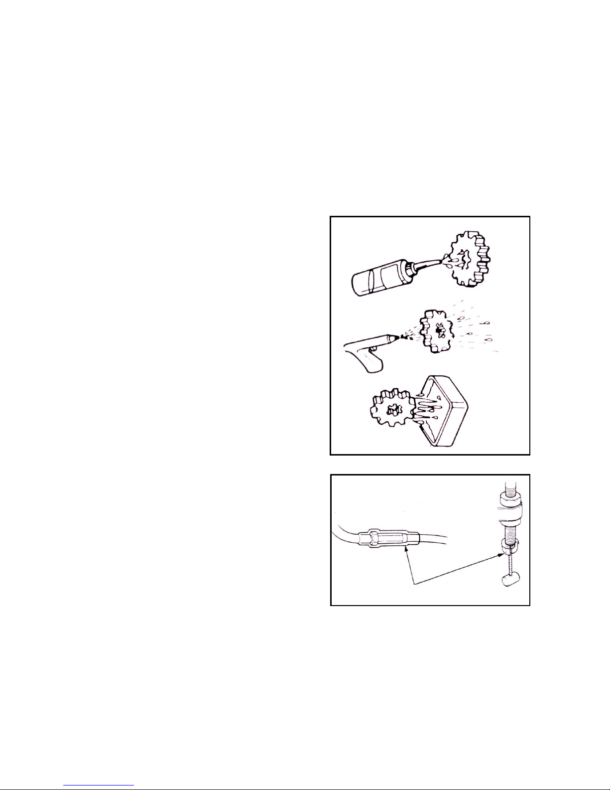
Installation of oil seal: the oil seal groove should be
filled with lubricating grease, check whether the oil seal
is smooth and may be damaged.
- 7 -
KS MOTORCYCLES - https://ksmotorcycles.com
Installation of rubber hose (fuel, vacuum, or coolant):
its end should be plugged into the bottom of connector,
so that there is enough place at the hose to clamp the
connector. Rubber or plastic dirt-proof boots should be
fitted at the original design position.
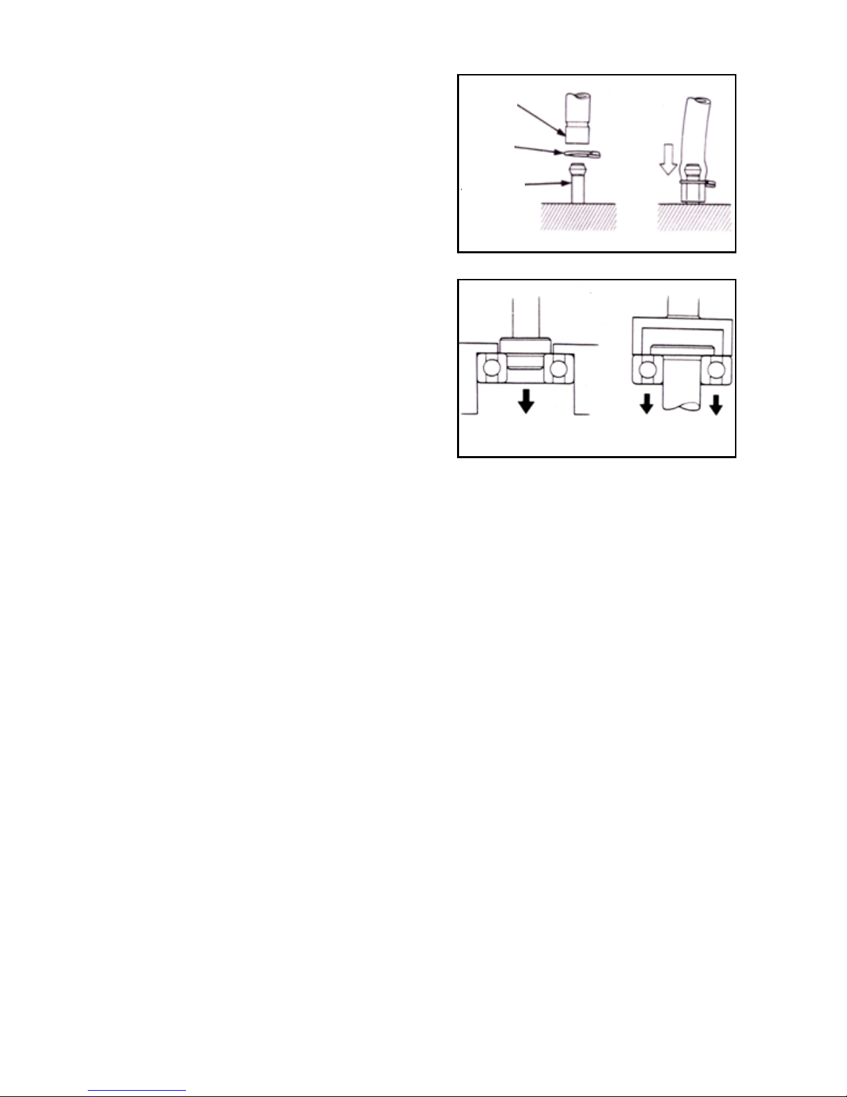
Disassembly of ball bearing: use tools to support one or
two (inner and outer) bearing rolling rings. If the
force is applied to only one rolling ring (either inside or
outside), the bearings may be damaged when being
disassembled and they must be replaced.
Groove
Clamp
Connector
Bearing may be damaged in the two examples
above.
- 8 -
KS MOTORCYCLES - https://ksmotorcycles.com
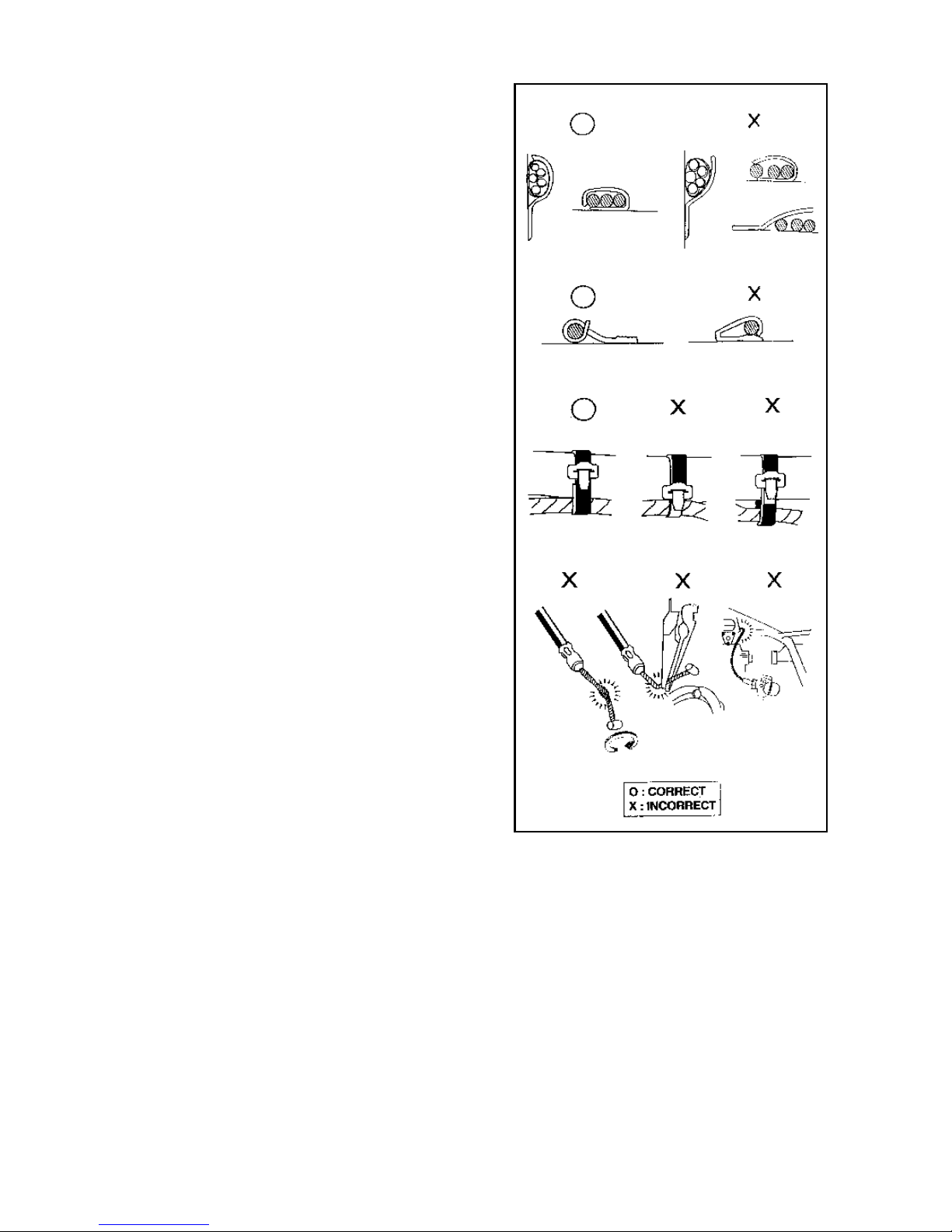
Loose cable is a potential safety hazard of electrical
safety. Check the next cable after clamping the cable, to
ensure electrical safety;
Wire clamps are not allowed to bend in the direction of
the solder joint;
Bundle the cable at the designated location;
Cables are not allowed to be placed at the end of frame
or at the corners;
Cables are not allowed to be placed at the ends of bolts
or screws;
Keep cables away from heat source or the position
where the cable may be caught during movement;
Cables should not be kept too tight or loose when being
placed along the faucet handle, and must not interfere
with adjacent parts in any steering position;
Cables should be smoothly placed and must not be
twisted or knotted;
Before con
nectors are mated, check whether the
connector sheath is damaged and the connector is
opened excessively;
If the cable is at a sharp or corner, please protect it with
tape or a hose;
After the cable is repaired, please bind it up reliably
with tape;
The control wire must not bend or twist. If the control
line is damaged, inflexible operation may be caused;
- 9 -
KS MOTORCYCLES - https://ksmotorcycles.com
Motorcycle identification
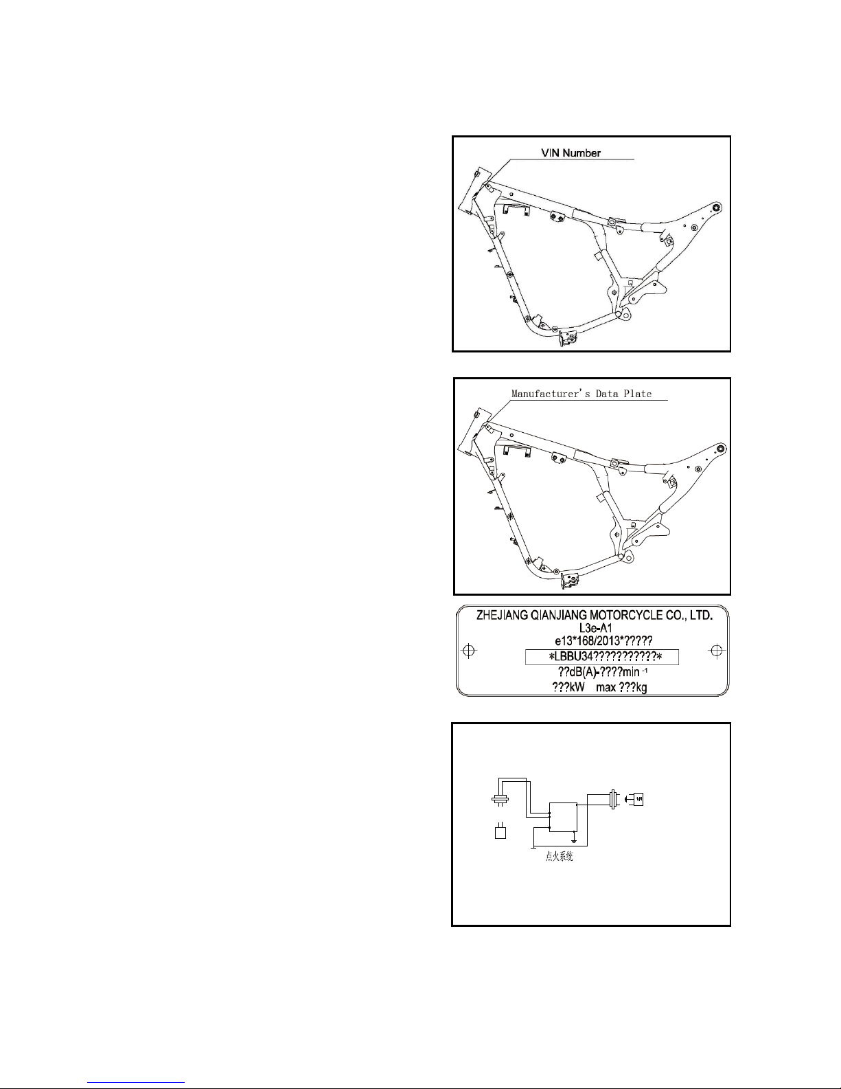
1.The frame serial number
①
is:
*LBBU3400?????????*, as shown in the figure. The
10th digit of vehicle identification code is the year, the
11th digit is the production factory code, and a “*”
mark is added at the beginning and the end of the frame
number.
2. Frame nameplate riveting position, as shown in the
figure.
Frame nameplate, as shown in the figure.
3. Serial number of engine ① is marked at the housing
of crankcase, as shown in the figure.
Engine number: QJ157FMI-A*□□□□□□□*
白
/
绿
蓝
/
白
触发头
ECU
黑/红1
黑/白1
点火电源
- 10 -
KS MOTORCYCLES - https://ksmotorcycles.com

Important notes
1. Please use the parts from dealers. Damage may be caused to the engine when the parts that do not meet the design
specifications of dealers used.
2. O
nly metric tools can be used for maintenance work. Metric bolts, nuts and screws are not interchangeable with
imperial fasteners.
3. During reassembly work, use new washers, O-rings, split pins and locking plates.
4. When tightening bolts or nuts, first tighten the bolts with large diameter or leaning to the inner side, and then
gradually tighten them to the specified torque in the diagonal order, unless otherwise specified.
5. Wash the removed parts with a cleaning solution. Lubricate all sliding surfaces before assembly.
6. After assembly, check whether all parts have been correctly installed and operated.
7. Degrease and remove oil before measurement. Add recommended lubricant to the lubrication location during
assembly.
8. When the engine and drive system need to be stored for a long time after being disassembled, please apply
lubricant to the surface of the parts to prevent rust and dust.
Special tools
Special tool refers to a tool specially designed for assembling or disassembling some parts of motorcycle and
using it on a specific location. Appropriate special tools are indispensable for complete and accurate adjustment
and assembly operations. Parts should be disassembled and assembled safely, reliably and quickly using special
tools, so as to improve work efficiency and save labor.
1. Tools for maintenance of engine
When disassembling the engine, certain parts can be smoothly assembled and disassembled only using
specially designed tools.
The list and pictures of special tools for the disassembly and assembly of engine parts are shown in Tables
1-1 and 1-2.
Table 1-1
Name
Remarks
Special socket wrench
Clutch holder
Flywheel puller
Feeler gauge
Bearing removal tool
Bearing installation tool
Oil seal replacer
Disassembly tool handle
Piston pin pull-out device
Piston ring opening clamp
Spark plug socket wrench
Measuring clutch thickness
Cylinder diameter tester
Dial gauge
Used to remove the flywheel bolts, Fig. 1-3
Fig. 1-4
Fig. 1-5
Fig. 1-6
Fig. 1-7
Fig. 1-8
Fig. 1-9
Fig. 1-10
Fig. 1-11
Fig. 1-12
Fig. 1-13
Fig. 1-14
Fig. 1-15
Measure inner diameter of piston pin, Fig. 1-16
Table 1-2
- 11 -
KS MOTORCYCLES - https://ksmotorcycles.com
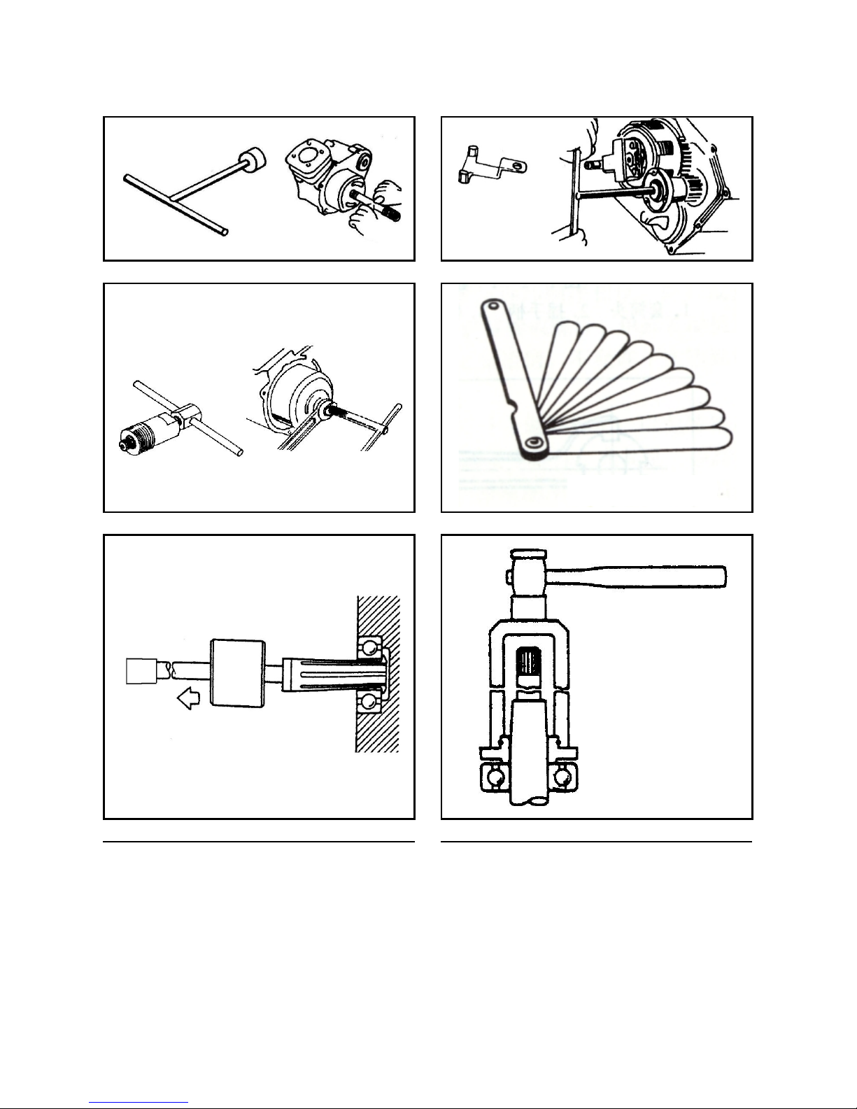
Fig. 1-3
Fig. 1-4
Fig. 1-5
Fig. 1-6
Fig. 1-7
Fig. 1-8
Feeler gauge
- 12 -
KS MOTORCYCLES - https://ksmotorcycles.com
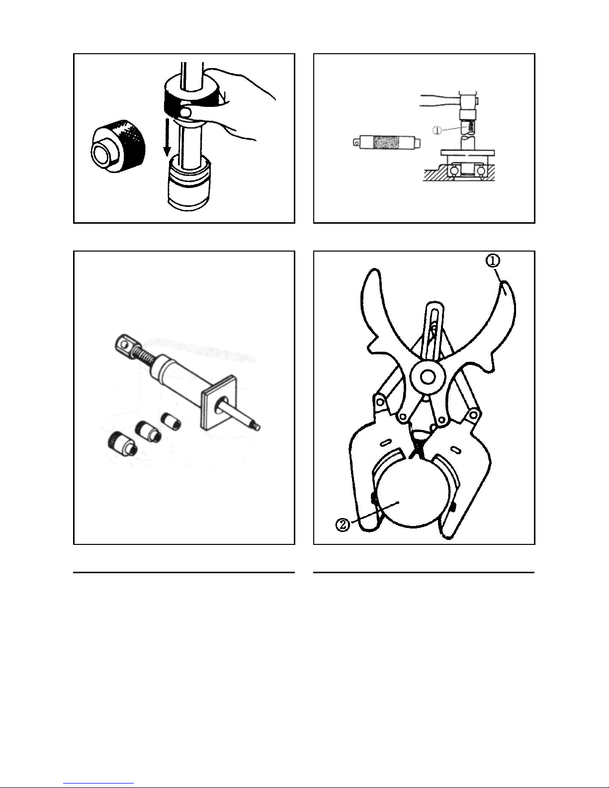
Fig. 1-9
Fig. 1-10
①Handle
Fig. 1-11
Fig. 1-12
① Opening clamp ②Piston
- 13 -
KS MOTORCYCLES - https://ksmotorcycles.com
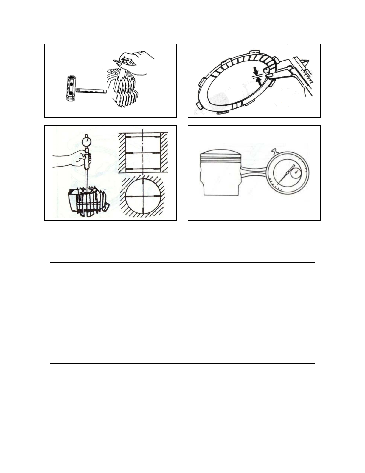
Fig. 1-13
Fig. 1-14
Fig. 1-15
Fig. 1-16
2. Tools for chassis maintenance
The list and pictures of common and special tools for the disassembly and assembly of chassis parts are shown in Tables 1-17
and 1-18.
Table 1-17
Name Remarks
Torque wrench
Allen wrench
Socket wrench
Micrometer
Magnetic frame, V-shaped block
Dial gauge
Vernier caliper
Spring snap ring pliers
Knock-on screwdriver
Front fork oil seal installation tool
Front fork seal driving tool
Steering nut wrench
Fig. 1-19
Fig. 1-20
Fig. 1-21
Fig. 1-22
Fig. 1-23
Fig. 1-24
Fig. 1-25
Fig. 1-26
Fig. 1-27
Fig. 1-28
Fig. 1-29
Fig. 1-30
(1) Common tools for chassis maintenance
Table 1-18 (continued)
- 14 -
KS MOTORCYCLES - https://ksmotorcycles.com
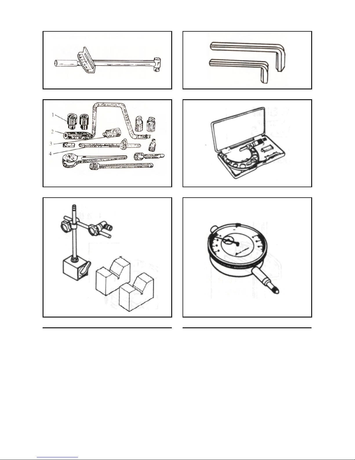
Fig. 1-19
Fig. 1-20
Fig. 1-21
Fig. 1-22
Fig. 1-23
Fig. 1-24
1. Socket head 2. Jiggle bar 3. Ratchet wrench 4. Connecting rod
- 15 -
KS MOTORCYCLES - https://ksmotorcycles.com
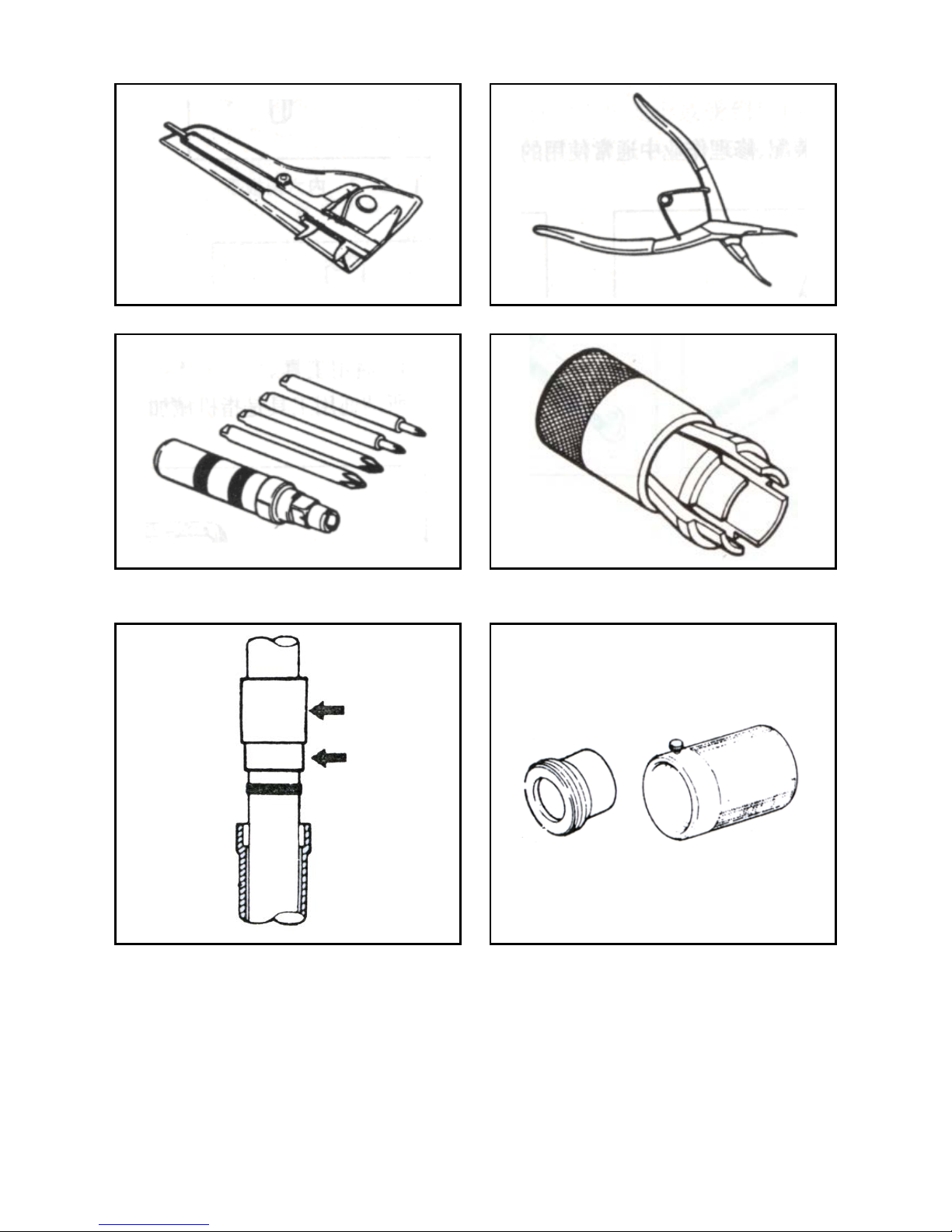
Fig. 1-25
Fig. 1-26
Fig. 1-27
Fig. 1-28
(2) Special tools for maintenance of chassis: Front fork seal driving tool.
Fig. 1-29
(3) Steering nut wrench.
- 16 -
KS MOTORCYCLES - https://ksmotorcycles.com
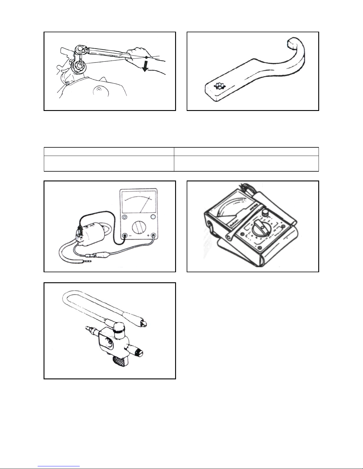
Fig. 1-30
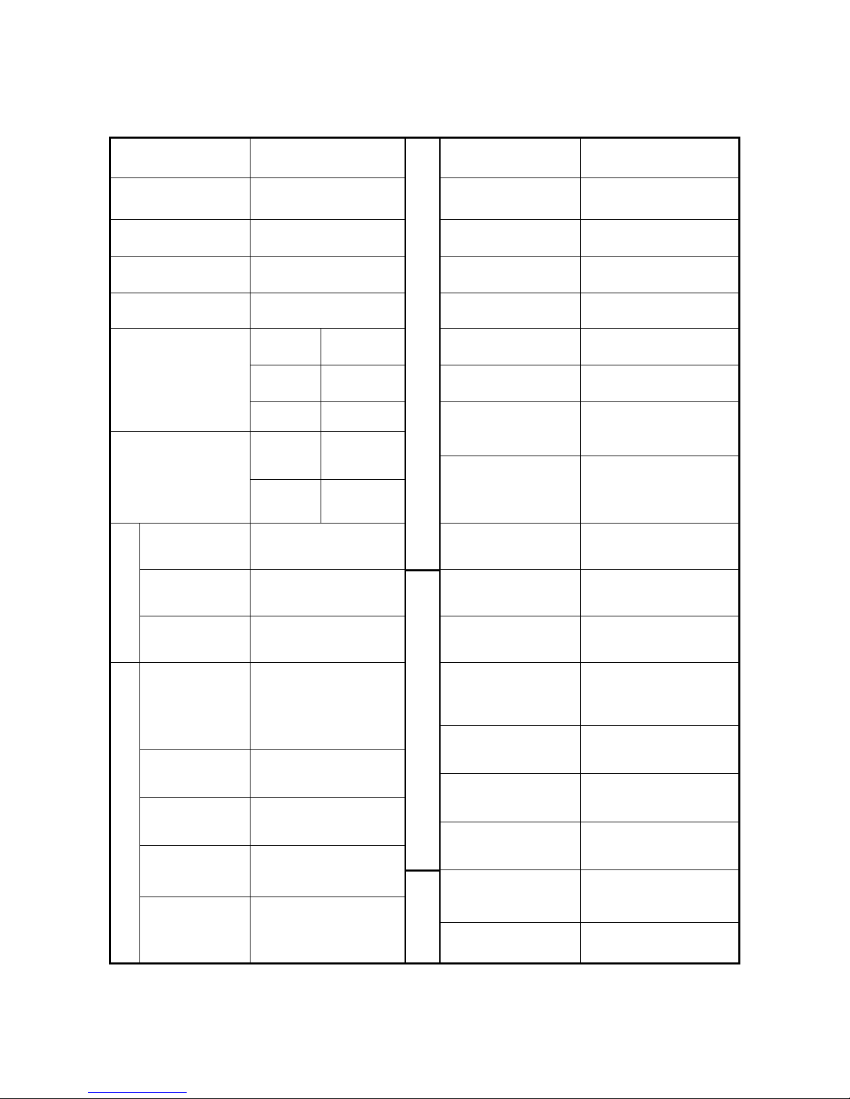
3. Tools for electrical parts
The list and pictures of special tools for the testing of electrical parts are shown in Table 1-31 and 1-32.
Table 1-31
Name
Remarks
Multimeter
Ignition tester
Fig. 1-33
Fig. 1-34
Table 1-32 (continued)
Fig. 1-33
Fig. 1-34
- 17 -
KS MOTORCYCLES - https://ksmotorcycles.com
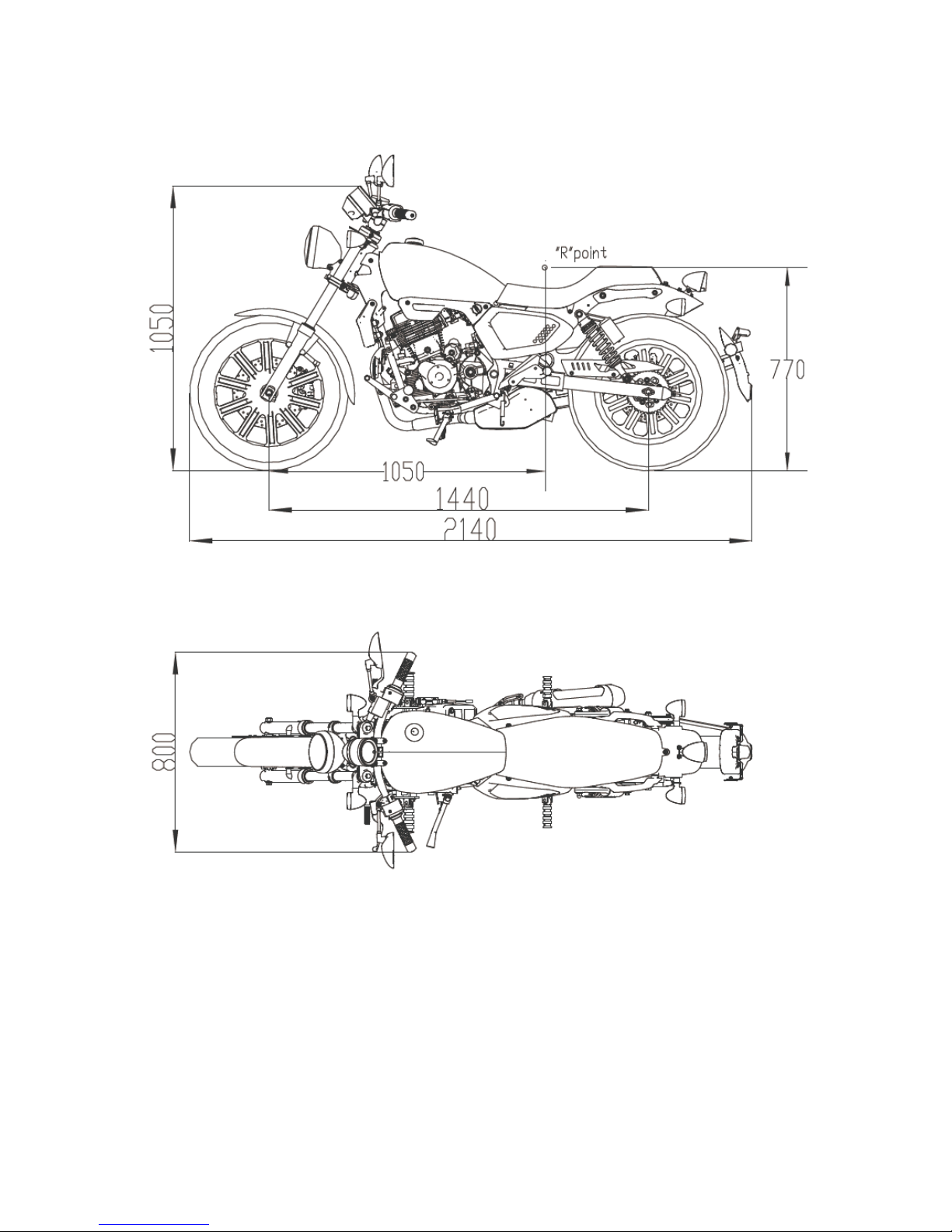
Specification table
Model K-LIGHT125 Engine type QJ157FMI
L (mm) 2140 Fuel type Unleaded gasoline
W (mm) 800
Number of
cylinders
1
H (mm) 1050
Inner diameter *
stroke
φ56.5×49.5
Wheelbase mm 1440 Total displacement 124cm³
Weight (kg)
(Curb weight)
Front
axle
69 Starting mode Electric / kickstarter
Rear
axle
76 Cooling mode Air-cooled
Total
145
Lubrication mode
Pressure and splash
lubrication
Tire
Specifications
Front tire
90/90-17
Engine
Air filter 3XG/sponge
Rear tire
130/90-15
Transmission gear
Clutch type
Wet multi-plate
friction type
Tank capacity 11.8L±0.5L
Speed-varying
mode
Five-speed
transmission
Performance
Throttle valve: 30C-21
Drive mode Chain drive Idle speed 1500±100rev/min
Electric equipment
Battery
capacity/type
12V6Ah
(YTX7A-BS)
Maximum torque 8.9Nm/7500rev/min
Maximum
horsepower
7.8kw/9000rev/min
Alternator
capacity
100W/5000rpm
Compression ratio
9:1
Spark plug D7RTC
Maximum speed 90km/h five-speed
Spark plug gap 0.7±0.1mm
Brake
Diameter of front
brake disc
φ280mm
Ignition mode ECU
Diameter of rear brake
disc
φ240mm
- 18 -
KS MOTORCYCLES - https://ksmotorcycles.com
- 19 -
KS MOTORCYCLES - https://ksmotorcycles.com
Fault diagnosis
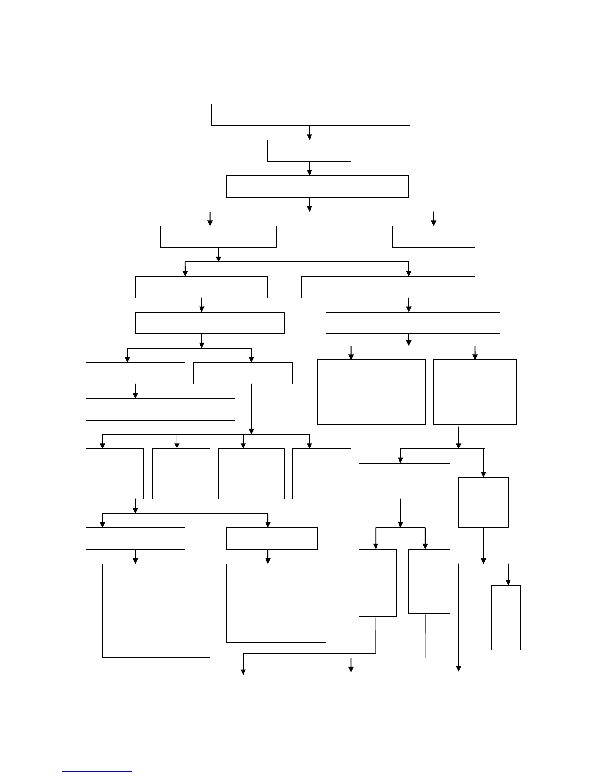
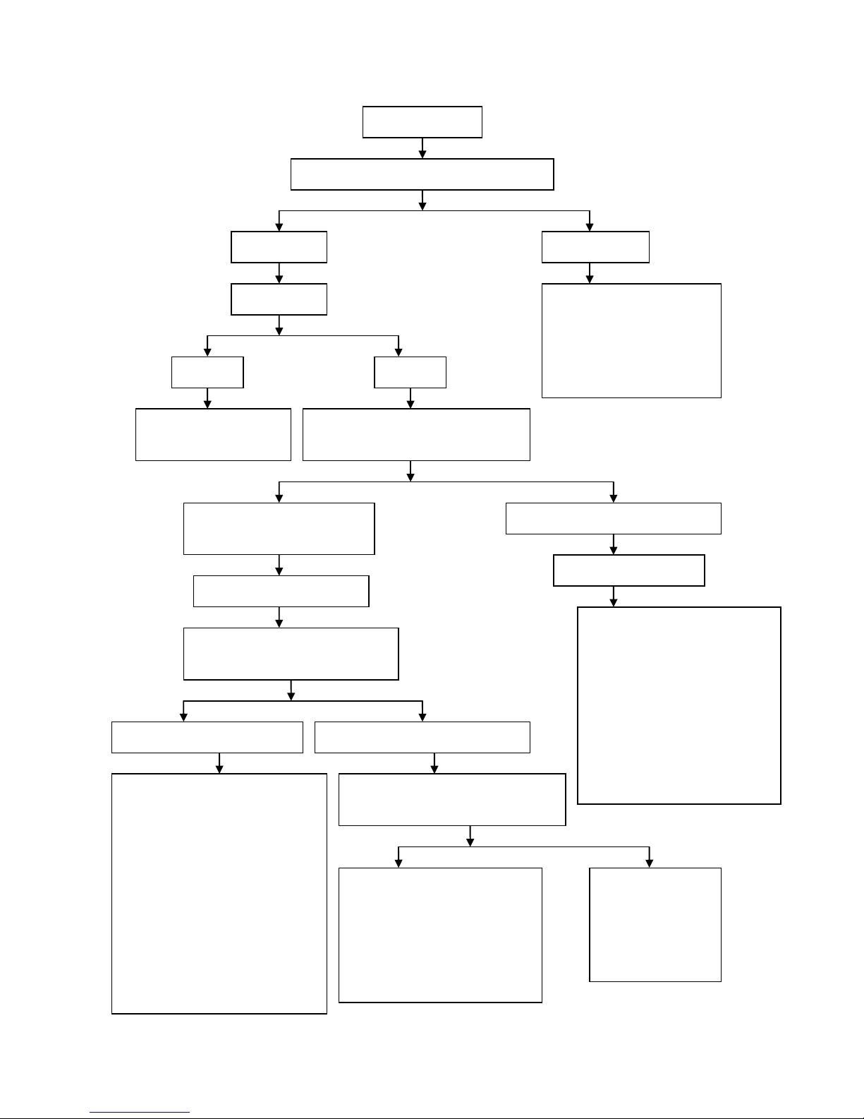
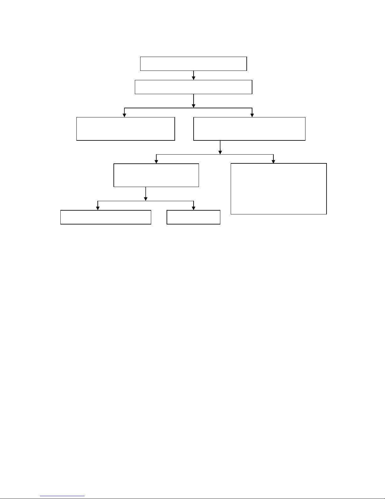
Diagnostic procedure for the fault that engine cannot be started or it is difficult to start the engine
Yes
No
Yes
Yes
No
Yes
No
Diagnostic procedure for the fault that engine cannot be
started or it is difficult to start the engine
Check the ignition
system
Remove the spark plug, and check whether there is
carbon between the electrodes of spark plug
Conduct spark-over test of spark
plug
Remove the carbon
deposit
There is weak spark or no spark
between electrodes
There is strong blue or blue or purple spark between
electrodes
Unscrew the spark plug cap and conduct the
high-voltage wire spark-over test
Check whether engine ignition is conducted in
correct time using ignition timing light
There is strong blue spark
There is weak spark or no
spark
Check whether there is faul t in the spark
plug and spark plug cap
Check the
supply of
ignition coil
Check whether
there is any open
circuit or short
circuit in the
ignition switch
Check whether
there is any open
circuit or short
circuit in the line of
ignition switch
Check whether
there is fault in
the CDI ignition
device
Test the compression
pressure of cylinder using
cylinder pressure gauge
Check
whether there
is gasoline in
the fuel tank
The
compressi
on
pressure
of cylinder
is normal
The
compressio
n pressure
of cylinder
is
insufficient
Fill
gasoline
Ignition system of
non-contact storage battery
Ignition system of
non-contact alternator
1. Check whether the bat tery
power is sufficient
2.
Check whether there is any
open circuit or short circuit
in the low-voltage circuit
3.
Check whether there is any
open circuit or short circuit
in the trigger coil
1. Check whether there is
any open circuit or short
circuit in the ignition
switch
2.
Check whether there is
any open circuit or short
circuit in the trigger coil
1. Check whether there is
fault in the ECU ignition
device
2.
Check whether the
alternator flywheel and
trigger coil are loosened
Check whether gasoline
flows out from the
throttle valve
Yes
No
- 20 -
KS MOTORCYCLES - https://ksmotorcycles.com
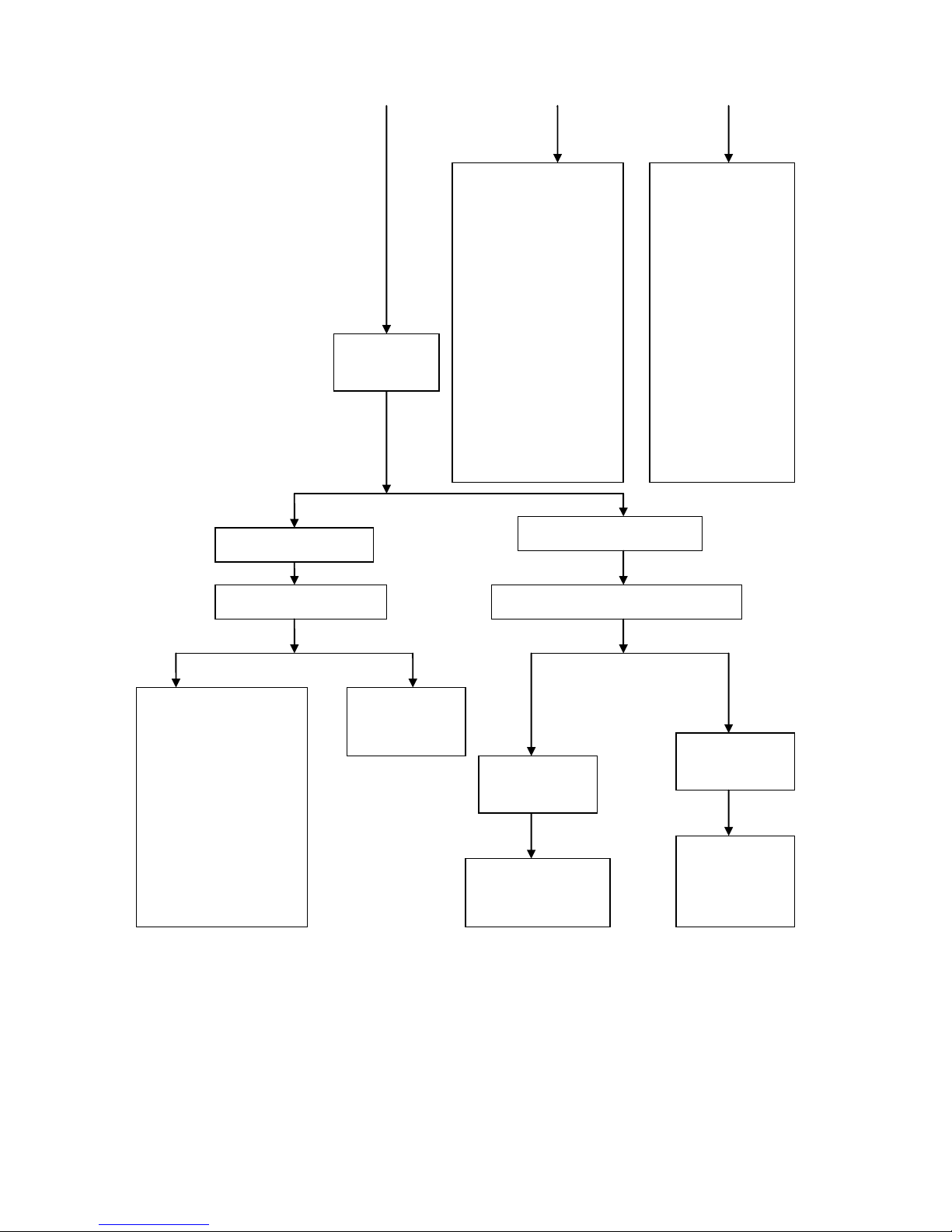
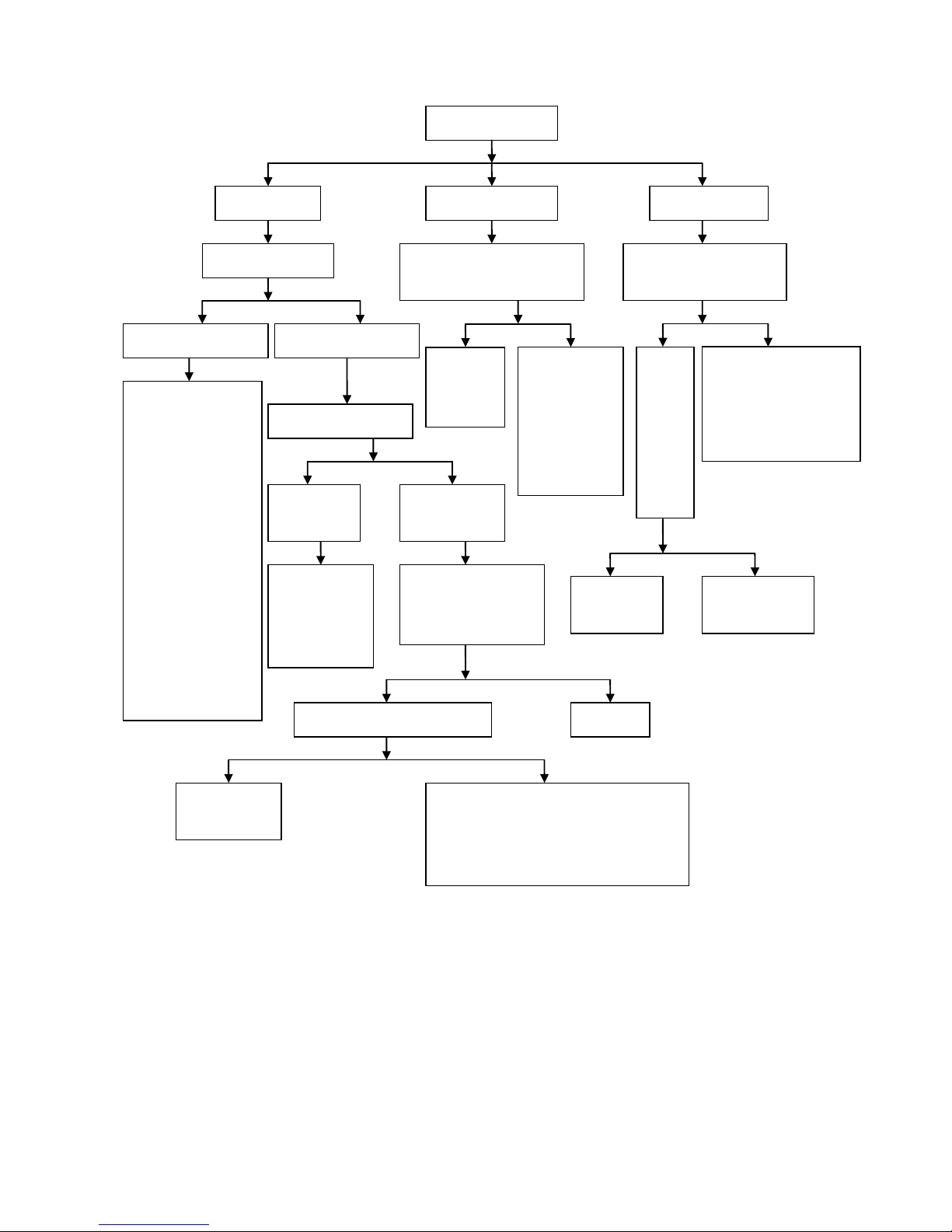
Yes
No
The electrode of spark plug is
wet
The electrode of spark plug is dry
Check the fuel injector for
overflow
Drip a small amount of gasoline in the cylinder
for trial start
1. Check the fuel injector
Check whether air
filter is blocked
It may flame out after
a short-time operation
It can continue to
work after startup
The inner part of throttle
valve is blocked or the
float is too high
There is a fault in the
starter device of
throttle valve
1. Check for air leakage at
the joint outside the
engine
2.
Check whether gas
distribution is con duc t e d
in correct time
3.
Check whether th e val ve
clearance is too small
4.
Check whether th e seal
between valve and valve
seat is good
5.
Check whether th e pi s ton
ring is stuck in the ring
groove or in la c k of
elasticity
6.
Check the wear of piston
ring and cylinder
1. Check whether the
air hole at fuel tank
cover is blocked
2.
Check whether fuel
filter and pump is
blocked
3.
Check whether th e
fuel pump is working
properly
Remove and check
the spark plug
- 21 -
KS MOTORCYCLES - https://ksmotorcycles.com
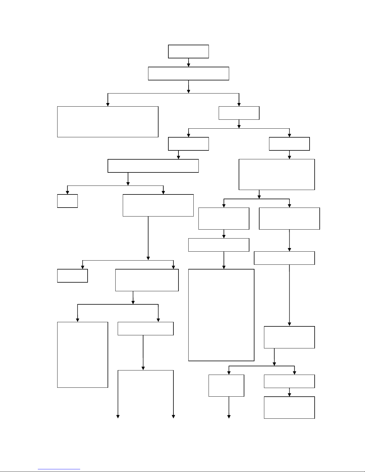
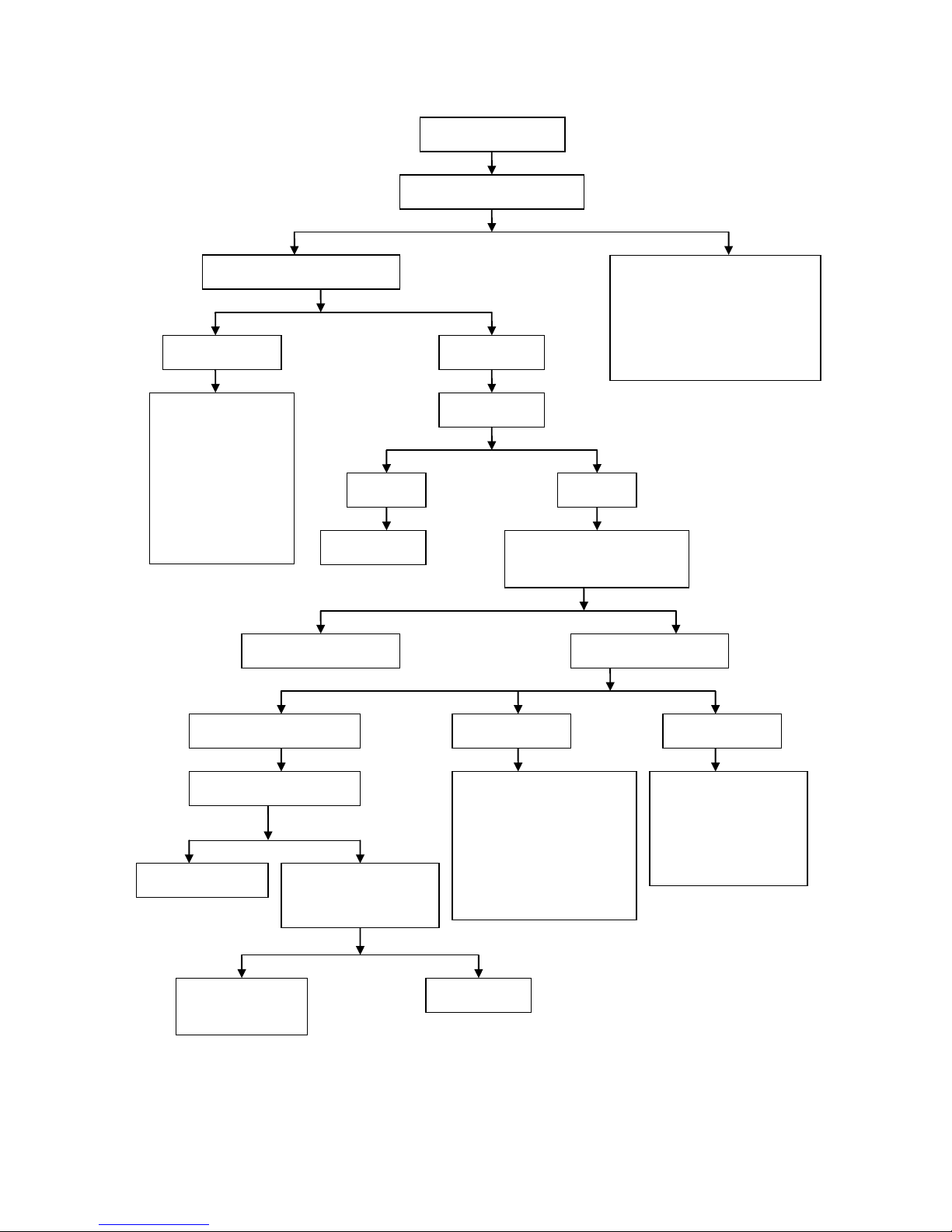
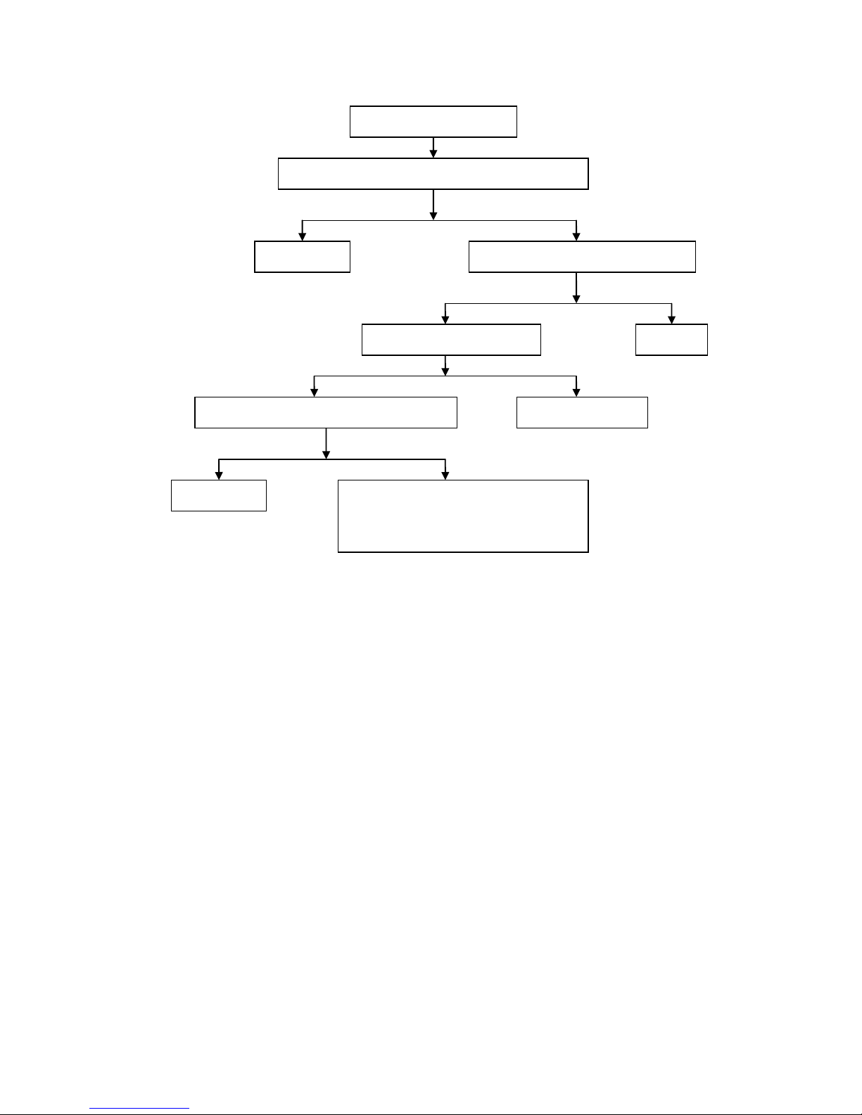
Engine overheating fault diagnosis procedure
Yes
No
Yes
No
Yes
No
No
Yes
Yes
No
Engine overheating
Check whether operatio n methods are
improper
1. Check whether the gasoline brand is too
low or gasoline is stored for too long time
2.
Check whether the engine has run at high
speed or overload for a long time during
driving
Check cooling
system
Air-cooled engine
Water-cooled
engine
Check whether there is too much sand or oil
in cooling fin
Start the engine. When the
temperature of engine is higher than
that of the thermostat, check t he
radiator and engine t emperature b y
hand touch
Clean
Check whether cooling fan and
wind scooper are damaged
(Forced air cooled engine)
The temperature of
radiator is basically the
same as that of engine
The temperature of radiator
is low and the temperature of
engine is high
The working cycle of water
cooling system is normal
The working cycle of water
cooling system is defective
Check and
eliminate
Check whether engine ignition
is conducted in correct time
using ignition timing light
1. Check whether the
cooling fin on the
radiator
is seriously damaged or
distorted
2.
Check whether there is
too much sand or oil in
cooling fin
3.
Check whether the
radiator cap is working
properly
4.
Check whether the
cooling fan is working
properly
Check the coolant
capacity in the radiator
1. Check whether
there is fault in the
CEU
2. Check whether the
alternator flywheel
and trigger coil are
loosened
Check whether clutch is
slipping
The coolant in
the radiator is
sufficient
There is no coolant in
the radiator
The coolant capacity in
the system is sufficient
- 22 -
KS MOTORCYCLES - https://ksmotorcycles.com
The clutch is
slipping
Handle it according
to 1.7
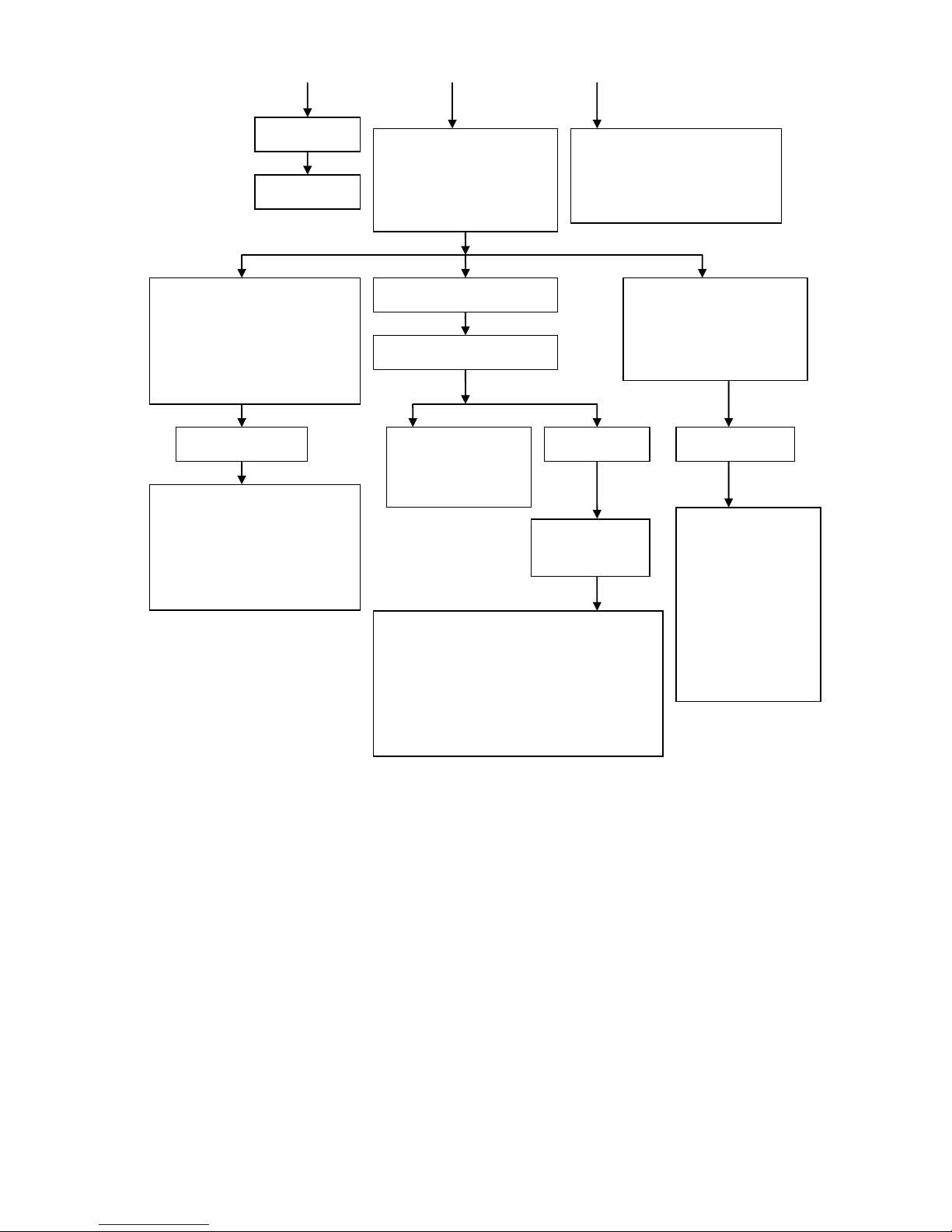
Remove the spark plug, observe
the color of the insulator group of
spark plug an d judge the mixing
ratio of combustible mixture
according to various abnormal
phenomena
1. Check whether the water pump is
working properly
2.
Check whether th e th er mostat is
working properly
3.
Check whether th e water pipe in
the system is blocked
The insulator group of spark plug is
black, and when the engine is running
at low to medium speed, the exhaust
muffler
will emit black smoke or blast,
acceleration performance becomes
poor, idle speed become unstable and it
easy to flame out, and it is normal
when running at a high speed.
The insulator group of spark plug
is brown
The insulator group of spark plug
is white, and the engine is
intermittently operate when
accelerating, the carburetor is
tempered, and engine power is
insufficient
Too thick combustible
mixture
1. Check whether air filter is
blocked
2.
Check whether th e starter device
of throttle valve is working
properly
The mixture ratio of combustible
mixture is normal
Check whether cylinder
block exhaust port and
exhaust muffler are
blocked due to excessive
carbon deposition
Check lubrication
system
Too thin combustible
mixture
Four-stroke engine
lubrication system
1. Check whether the
fuel pump is working
properly
1. Check whether the oil in the crankcase is
insufficient
2.
Check whether the viscosity of oil in the
crankcase is too low or it is too dirty
3.
Check whether oil filter is blocked
4.
Check whether th e fu el pump is working
properly
5.
Check whether th e lu brication oil passage is
blocked
- 23 -
KS MOTORCYCLES - https://ksmotorcycles.com
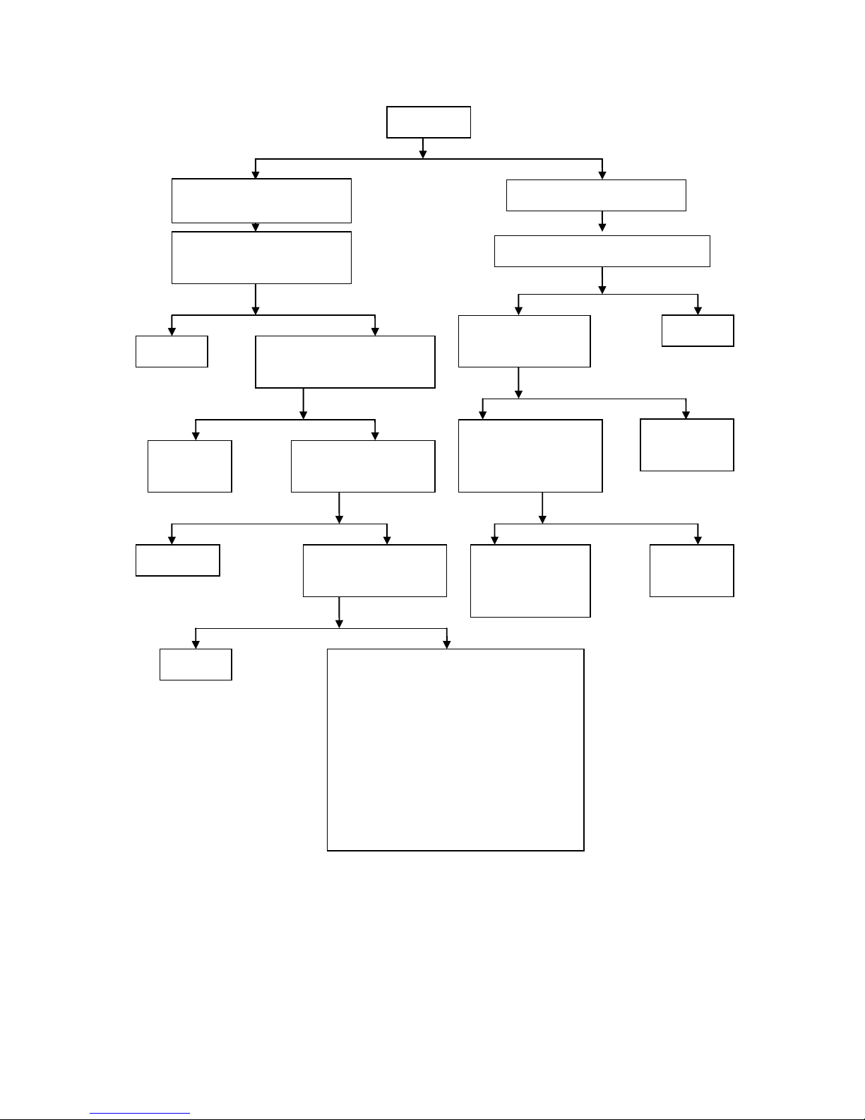
Fault diagnostic procedure for insufficient power of engine
Yes
No
The power of engine is
insufficient
Support the main parking frame to make the wheels
off the ground and rotate the wheels by hands
The wheels can be
rotated smoothly
The wheels can not
be rotated flexibly
Check tire pressure
1. Check whether the brake i s
stuck
2.
Check wheel bearin gs for
excessive wear or damage
3. Check whether the spacer bush
in the hub is missing or too
short
The pressure
is too low
The pressure
is normal
Check whether the tire valve
core leaks and tires are
punctured or broke n
Remove the spark plug, plug the threaded hole
of spark plug with fingers, then press the start
button or stamp down the start lever
You can feel that gas is rushing
outwards using your fingers and it is
purring
You can not feel that gas is rushing
outwards using your fingers
The compression pressure of
cylinder is normal
The compression pressure of
cylinder is insufficient
1. Check for air leakage at the jo int
outside the engine
2.
Check whether gas distribution is
conducted in correct t ime
3.
Check whether th e val ve cl earance
is too small
4.
Check whether th e seal between
valve and valve seat is good
5.
Check whether the piston ring is
broken or stuck in the ring groove
or in lack of elasticity
6.
Check the wear of piston ring and
cylinder
Start the engine, slowly increase the
throttle,and observe th e changes in the
engine speed
The engine speed can increase with the
increase of throttle
The engine speed cannot increase with the
increase of throttle
Check whether engine ignition is conducted in
correct time using ignition timing meter
1. Check whether the clutch is slipping
2.
Check the drive belt for excessive
wear
3. Check whether the cent r ifugal roller of
drive pulley is worn excessively
4.
Check whether the conical surfaces of
driving wheel and moving friction
wheel are excessively worn or worn
into grooves
5.
Check whether the conical surfaces of
driven wheel or moving driven wheel
are excessively worn or worn into
grooves
6.
Check whether the rolling path on the
inner end surface of moving friction
wheel for excessive wear or pits due to
squeezing
1. Check whether the fuel supply system
is running smoothly
2.
Check whether throttle, air filter and
exhaust muffler are blocked
3.
Check wheth er the vacuum
diaphragm of plunger valve on
throttle body is cracked or damaged
4.
Check wheth er the throttle float
height is improper
1. Check whether there
is fault in the ECU
ignition device
2.
Check whether th e
alternator flywheel
and trigger coil are
loosened
- 24 -
KS MOTORCYCLES - https://ksmotorcycles.com
Fault diagnostic procedure for poor idle speed of engine
Yes
No
Yes
No
No
Yes
Yes
No
Yes
No
The idle speed of engine
is poor
The idle speed of engine
is too high
Engine does not
have idle speed
The idle speed of
engine is instable
Check the compression
pressure of cylinder
Move the throttle valve with
hands, to check whether it has
been completely closed
Check whether engine ignition
is conducted in correct time
using ignition timing light
The compression pressure
of cylinder is insufficient
The compression pressure
of cylinder is normal
1. Check the joints
outside the engine for
air leakage
2.
Check whether gas
distribution is
conducted in correct
time
3.
Check whether the
valve clearance is too
small
4.
Check whether the
leak tightness
between valve and
valve seat is good
5.
Check whether the
piston ring is broken
or stuck in the ring
groove or in la c k of
elasticity
6.
Check the wear of
piston ring and
cylinder
Readjust the idle speed of
electronic fuel inject or
Check
whether the
metering hole
of idle speed
is too large
Check whether the
steel wire rope of
throttle control
cable can be pulled
flexibly in the
cable jacket and
whether the throttle
spring is too soft
1. Check whether there is
fault in the ECU
ignition device
2.
Check whether th e
alternator f
lywheel and
trigger coil are
loosened
Engine has idle
speed after
adjustment
Engine still does
not have idle speed
after adjustment
Air adjusting screw
or adjusting screw
of throttle is not
adjusted proper ly
Check whether the airway
of throttle is blocked
Clean and
dredge
Check whether throttle opening is
too large
Adjust the throttle
valve opening to
the standard value
1. Check the heat insulator of throttle valve
for cracks
2. Check whether the mounting nut connected
to the throttle valve is loosened
3.
Check fuel pump
4.
Check reed valve for air l eakage
Adjustable
electrode gap
Check the mixing
ratio of combustible
mixture
Check
whether
the spark
plug
clearance
is too
small
- 25 -
KS MOTORCYCLES - https://ksmotorcycles.com
Fault diagnostic procedure for excessive oil consumption of engine
Yes
No
Yes
No
Yes
No
Yes
No
Engine fuel consumption
exceeds the standard
Check whether the operat ion
method is correct
Support the main parking frame and
turn the wheel by hand
1. Check whether the motor cycle is
running at overload, or not at
economic speed or at low gear
position
2. Check whether the gasoline grade
is correct
The wheels can not
be rotated flexibly
The wheels can be
rotated smoothly
1. Check whether the
brake is stuck
2.
Check wheel
bearings for
excessive wear
3.
Check whether th e
spacer bush in the
hub is missing or too
short
Check tire pressure
The pressure
is too low
The pressure
is normal
Inflate as required
Check fuel tank, fuel pump, oil
pipeline, throttle and other parts
for oil leakage
Eliminate it according to
actual situations
Check the mixing ratio of
combustible mixture
The mixture ratio of
combustible mixture is normal
Too thick
combustible mixture
Too thin combustible
mixture
Check whether the idle speed of
engine is too high
1. Check whether air filter is
blocked
2. Check whether throttle valve
is too low
1. Check whether throttle
valve is blocked
2.
Check whether thr ot tle
valve is too high
Check and adjust
carburetor
Check whether the
clutch drive belt is
slipping
Check the ignition
system
Check whether engine
ignition is conducted in
correct time using ignition
timing light
- 26 -
KS MOTORCYCLES - https://ksmotorcycles.com
Fault diagnostic procedure for clutch slipping
No
Yes
No
Yes
No
Yes
No
Yes
Yes
No
No
Yes
Yes
No
The clutch is
slipping
Automatic centrifugal dry brake
shoe clutch is slipping
Check whether the free stro ke of
clutch grip is within the scope of
10mm~20m
Readjust
Check whether the wire rope of
clutch control cable can be flexibly
pulled in the cable jacket
Check whether the brake
shoe of clutch is
excessively worn
Replacement of
complete set of
clutch brake shoe
Clean the oil
Check whether the contact
area of the friction pad of
clutch brake shoe and
clutch
friction plate is less than 70%
Cleaning,
lubrication or
replacement
Check whether the oil level
in the crankcase is too low
Check whether the
contact surface between
clutch friction plate and
brake shoe is
excessively worn
Repair or replace
clutch brake
shoe
Supplement oil
Check whether the viscos ity
of oil in the crankcase is too
low or it is too dirty
Replace oil
1. Check whether the clutch lever adjustment s cr ew
is not adjusted properly
2.
Check whether the holddown bolt of clutch
spring is loosened
3.
Check the friction pad of clutch for ablation or
excessive wear
4. Check whether the clutch spring is insufficiently
elastic
5.
Inspect whet her the contact surfaces between
clutch driven hub and clutch pressure plate and
clutch friction pad ar e excess ively worn
6.
Check whether the driving and driven hub gear
grooves of clutch have been worn to a zigzag
shape
A number of clutches are slipping
under wet conditions during manual
operation
Check whether there is oil in the brake shoe
of clutch
- 27 -
KS MOTORCYCLES - https://ksmotorcycles.com
Fault diagnostic procedure for blue and white dense smoke of four-stroke engine exhaust silencer
Yes
No
No
Yes
Yes
No
Blue and white dense smoke of four-stroke
engine exhaust silencer
Check whether the oil level in the crankcase exceeds
the upper marking line
Excessive oil is added in the crankcase,
excess oil should be rel eas ed so that the oil
level does not exceed the u pper marking line
1. Check whether cylinders, pistons and
piston rings are excessively worn
2.
Check whether the piston ring is
insufficiently stretched or stuck in the
ring groove
3.
Check whether the piston ring openings
are staggered
Check whether the fit clearance
between valve and valve gui de pipe is
too large
Check whether valve and valve guide
have been excessively worn
Valve seal has been
damaged
Start the engine so that it is running at a high speed,
remove the oil gauge and check whether smoke is
emitted in the oil filler nozzle
- 28 -
KS MOTORCYCLES - https://ksmotorcycles.com
Diagnostic procedure for the fault that the clutch is not completely disengaged
No
Yes
No
Yes
Yes
No
Yes
No
The clutch is not completely
disengaged\
Check whether the free stroke of clutch grip is within the scope
of 10mm~20m
Readjust
Check whether the adjusting screw of clutch
push rod is not adjusted properly
Readjust
Check whether the elastic force of
clutch spring is even
Replace the whole set of
clutch spring
Check whether the driving and driven hub gear
grooves of the clutch are worn into serrated shape
Repair or replace
1. Check whether the driven disc of clutch is
warped or deformed
2.
Check whether th e parts of the clutch control
mechanisms such as the pus h camshaft and
the push rod are excessively worn
- 29 -
KS MOTORCYCLES - https://ksmotorcycles.com
 Loading...