

1
LoRa Interface Converter & DI/DO Controller
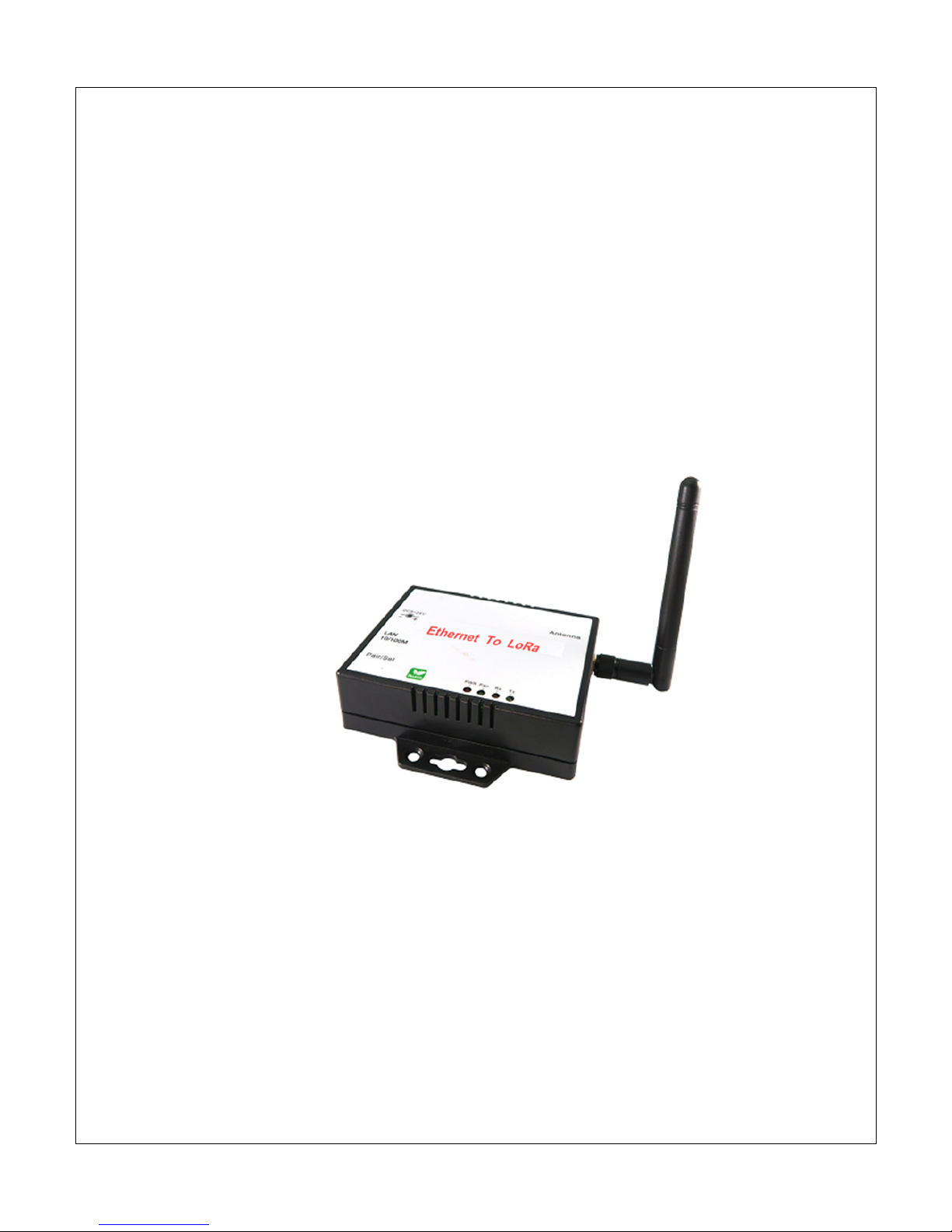
LR-201-E
LR-201-S
LR-201-U
LR-201-DIO
User Manual
Edition: 201807v1.0
http://www.tcpipweb.com
*** this document subject to change without prior notice.

2
Table of Contents
1.Introduction
------------------------------------------------------------------------------------------------------------------------------------------3
1.1 Applications ---------------------------------------------------------------------------------------------------------------------------------------------------------- 4
1.2 Packaging -------------------------------------------------------------------------------------------------------------------------------------------------------------- 4
1.3 Product Specifications -------------------------------------------------------------------------------------------------------------------------------------------- 5
1.3.1 LR-201-E : Ethernet To LoRa ----------------------------------------------------------------------------------------------------------------------------- 5
1.3.2 LR-201-S : RS-232/422/485 To LoRa------------------------------------------------------------------------------------------------------------------ 6
1.3.3 LR-201-U : USB To LoRa ----------------------------------------------------------------------------------------------------------------------------------- 7
1.3.4 LR-201-DIO : LoRa Digital I/O Controller ----------------------------------------------------------------------------------------------------------- 8
2. Product Views
---------------------------------------------------------------------------------------------------------------------------------------9
2.1 LR-201-E : Ethernet To LoRa------------------------------------------------------------------------------------------------------------------------------------ 9
2.2 LR-201-S : RS-232/422/485 To LoRa ------------------------------------------------------------------------------------------------------------------------ 9
2.3 LR-201-U : USB To LoRa ---------------------------------------------------------------------------------------------------------------------------------------- 10
2.4 LR-201-DIO : LoRa to Digital I/O Controller ------------------------------------------------------------------------------------------------------------ 10
2.5 Outlined Components ------------------------------------------------------------------------------------------------------------------------------------------ 11
2.5.1 DC-IN Power Outlet--------------------------------------------------------------------------------------------------------------------------------------- 11
2.5.2 Ethernet LAN Port ----------------------------------------------------------------------------------------------------------------------------------------- 11
2.5.3 Serial Port (RS-232, RS-422/485) -------------------------------------------------------------------------------------------------------------------- 11
2.5.4 2 DI / 2 DO port -------------------------------------------------------------------------------------------------------------------------------------------- 11
2.5.5 Reset Button------------------------------------------------------------------------------------------------------------------------------------------------- 11
2.6 LED Indicators------------------------------------------------------------------------------------------------------------------------------------------------------ 11
3. Wiring Architecture
------------------------------------------------------------------------------------------------------------------------------ 12
3.1 Ethernet + LoRa --- air ---- LoRa + Serial Interface ----- Machine------------------------------------------------------------------------------- 12
3.2 USB Interface + LoRa --- air ---- LoRa + Serial Interface ---- Machine------------------------------------------------------------------------- 12
3.3 Ethernet + LoRa --- air ---- LoRa + Serial DI/DO Interface ----- DI/DO ------------------------------------------------------------------------ 12
3.4 Serial Interface + LoRa --- air ---- LoRa + Serial Interface ----- Machine --------------------------------------------------------------------- 12
3.5 Star topology ------------------------------------------------------------------------------------------------------------------------------------------------------- 13
4. LoRa module Setting Utility
--------------------------------------------------------------------------------------------------------------------- 14
4.1 LoRa Setting Tool factory default--------------------------------------------------------------------------------------------------------------------------- 14
4.2 Dip Switch ----------------------------------------------------------------------------------------------------------------------------------------------------------- 15
5. LoRa setting process
----------------------------------------------------------------------------------------------------------------------------- 15
6. Ethernet to LoRa settings
----------------------------------------------------------------------------------------------------------------------- 17
7. Serial Interface to LoRa Settings
--------------------------------------------------------------------------------------------------------------- 20
8. USB to LoRa Settings
----------------------------------------------------------------------------------------------------------------------------- 20
9. LoRa to DI/DO: Modbus codes
----------------------------------------------------------------------------------------------------------------- 20
-------------------------------------------------------------------------------------------------------------------------------------------- 21
Appendix A
3
1. Introduction
Thank you for using LoRa interface gateway in your system work. These LoRa gateways
provide the way of connecting IoT remote units to a Local Area Network (LAN) or Host
Computer from long distance. The data transmission via LoRa gateways mainly
intended for the ISM (Industrial, Scientific, and Medical) frequency bands at 862-932 MHz.
The gateway has been built with the module integrated many RF functions and PA to
make the maximum output power up to +20dBm.
LoRa Interface Gateways are packaged in a plastic case well suited for industrial
environments. LoRa Interface devices have different models for converting to Ethernet,
USB, Serial ports (RS-232, RS-422/485) and DI/DO controller. Configuration is easy to
set up via web page and utility tool.
The following topics are covered in this chapter:
Applications
Packaging
Specifications

4
1.1 Applications
● Automation and safety alarm in the community.
● Various automated smart meters, such as water meter, gas meter and
electricity meter.
● Long range communication data collection and integration.
● Outdoor information monitoring and collection, such as temperature,
humidity and air quality information.
● Electricity facilities measurement and management, such as smart
street lighting.
● Agriculture and animal husbandry monitoring and management.
1.2 Packaging
LoRa Interface Gateway attached with the following items:
1 unit of Gateway device.
1 unit of Power Adaptor, 9V or 12V DC, 500mA (option)
1 unit of Antenna
Documentation & Utility CD
NOTE: Inform your sales representative if any of the above items missing or damaged.

5
1.3 Product Specifications
1.3.1 LR-201-E : Ethernet To LoRa
CPU : 32 bits MCU ,40 MHz , 16KB SRAM, 128KB Flash ROM
Support Modbus & Transparent
LoRa : Semtech SX1272
● Freq. : ISM band 862 ~ 936MHz
● Receiver Sensitivity : -137 dBm
● Transmit Output Power : 20 dBm
● Sleep Current : 3uA (at power down state)
● TX current < 140 mA@20 dbm , RX current < 10 mA
● Security processor ( 128/192/256 bits AES )
● Packet engine up to 256 bytes with CRC
● Antenna : SMA Type , 2 dBi , changeable
● Distance : Up To 1500~7500 Meters in free space
● Data Rate : 0.244 ~ 18.2K bps (LoRa) / 300 K bps (FSK)
● Application mode : Star
Ethernet Port
● Port Type:RJ-45 Connector
● Speed:10 / 100 Mbps ( Auto Detect )
● Protocol:ARP , IP , ICMP , UDP , TCP , HTTP , DHCP
● Mode:TCP Server / TCP Client / UDP / Virtual Com / Pairing
● Setup:HTTP Browser Setup ( IE )
● Security:Login Password
● Protection:Built-in 1.5KV Magnetic Isolation
● Modbus TCP To RTU Slave & Modbus TCP To ASCII Slave Mode
● Modbus RTU To TCP Slave & Modbus ASCII To TCP Slave Mode
Setup Tool : Windows Utility
Power : DC 9 ~ 24V / 150mA@ 9V , 60mA@ 24V
Led Lamp : SYS (green) , Rx(red) , Tx(green)
Environment: Operating Temperature: -10℃〜70℃
Storage Temperature: -20℃〜80℃
Dimensions : 100 * 90 * 25 mm ( W * D * H )
Weight : 150 gm ( not include power )

6
1.3.2 LR-201-S : RS-232/422/485 To LoRa
CPU : 32 bits MCU ,40 MHz , 16KB SRAM, 128KB Flash ROM
Support Modbus & Transparent
LoRa : Semtech SX1272
Freq. : ISM band 862 ~ 936MHz
Receiver Sensitivity : -137 dBm
Transmit Output Power : 20 dBm
Sleep Current : 3uA (at power down state)
TX current < 140 mA@20 dbm , RX current < 10 mA
Security processor ( 128/192/256 bits AES )
Packet engine up to 256 bytes with CRC
Antenna : SMA Type , 2 dBi , changeable
Distance : Up To 5000 Meters in free space
Data Rate : 0.244 ~ 18.2K bps (LoRa) / 300 K bps (FSK)
Application mode : Star
Serial Port
No.of Port : RS-232/422/485 * 1 port ( auto Detect )
RS-232 : Rx , Tx , GND , RTS , CTS ( DB9 female )
RS-422 : Tx+ , Tx-, Rx+ , Rx- (Surge Protect )
RS-485 : Data+ , Data- (Surge Protect)
Built –in RS-422/RS-485 Terminal Resistor
Speed : 9600 bps〜115.2K bps
Parity : None , Odd , Even
Data Bit : 7, 8 / Stop Bit : 1 , 2
Setup Tool : Windows Utility
Power : DC 9 ~ 24V / 150ma @ 9V , 60ma @ 24V
Led Lamp : SYS (green) , Rx(red) , Tx(green)
Environment: Operating Temperature: -10℃〜70℃
Storage Temperature: -20℃〜80℃
Dimensions : 100 * 90 * 25 mm ( W * D * H )
Weight : 150 gm ( not include power )

7
1.3.3 LR-201-U : USB To LoRa
CPU :
32 bits MCU ,40 MHz , 16KB SRAM, 128KB Flash ROM
Support: only transparent
LoRa : Semtech SX1272
● Freq. : ISM band 862 ~ 936MHz
● Receiver Sensitivity : -137 dBm
● Transmit Output Power : 20 dBm
● Sleep Current : 3uA (at power down state)
● TX current < 140 mA@20 dbm , RX current < 10 mA
● Security processor ( 128/192/256 bits AES )
● Packet engine up to 256 bytes with CRC
● Antenna : SMA Type , 2 dBi , changeable
● Distance : Up To 5000 Meters in free space
● Data Rate : 0.244 ~ 18.2K bps (LoRa) / 300 K bps (FSK)
● Application mode : Star
USB Port
● No.of Port : USB * 1 port, Connector : USB type B
● Chipset : Silicon Laboratories CP2102
● Compliant : US1.0 , 1.1 , 2.0
● Baud Rates : Full speed 12 M bps
● Driver Support : Windows-98/ 2000/ XP/ 2003/ Vista /Win-7/Win-10
Mac Osx / Os9 / Linux2.4 / 2.6
Provide : USB driver
Setup Tool : Windows Utility
Power : DC 5V / 150mA @ 5V
Led Lamp : SYS (red) , Pairing (green) , Rx(red) , Tx(green)
Environment: Operating Temperature: -10℃〜70℃
Storage Temperature: -20℃〜80℃
Dimensions : 100 * 90 * 25 mm ( W * D * H )
Weight : 150 gm ( not include power )

8
1.3.4 LR-201-DIO : LoRa Digital I/O Controller
CPU : 32 bits MCU ,40 MHz , 16KB SRAM, 128KB Flash ROM
Support Modbus Protocol
LoRa : Semtech SX1272
Freq. : ISM band 862 ~ 936MHz
Receiver Sensitivity : -137 dBm
Transmit Output Power : 20 dBm
Sleep Current : 3uA (at power down state)
TX current < 140 mA@20 dbm , RX current < 10 mA
Security processor ( 128/192/256 bits AES )
Packet engine up to 256 bytes with CRC
Antenna : SMA Type , 2 dBi , changeable
Distance : Up To 5000 Meters in free space
Data Rate : 0.244 ~ 18.2K bps (LoRa) / 300 K bps (FSK)
Application mode : Star
Digital I/O
Digital Input * 2
3000VDC Isolation Protect ( Active High /Active Low Selectable )
Dry contact : Logic level 0 : close to GND , Logic level 1 : open
Wet contact : Logic level 0 : 0~3 V , Logic level 1 : 10 ~ 30 V
Digital Output * 2
Relay ( Active High /Active Low Selectable )
120V AC@10A , 240V AC@7A , 24V DC@10A
Setup Tool : Windows Utility
Power : DC 9 ~ 24V / 150ma @ 9V , 60ma @ 24V
Led Lamp : SYS (red) , Pairing (green) , Rx(red) , Tx(green)
Environment: Operating Temperature:-10℃〜70℃
Storage Temperature:-20℃〜85℃
Dimensions : 160 * 90 * 25 mm ( W * D * H )
Weight : 350 gm ( not include power )
9
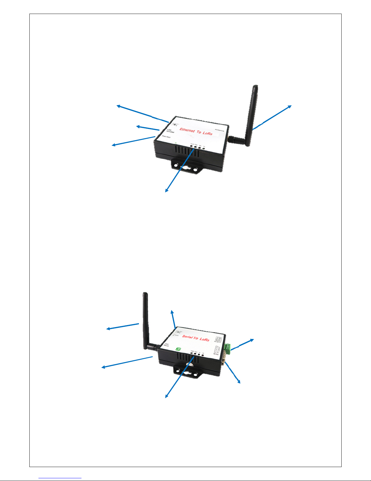
2. Product Views
2.1
LR-201-E : Ethernet To LoRa
2.2 LR-201-S : RS-232/422/485 To LoRa
LED Indicators
RS-422/485
RS-232
DC-IN Power Outlet
Antenna
Ethernet LAN port
Reset button
LED Indicators
DC-IN Power Outlet
Antenna
Reset button

10
2.3 LR-201-U : USB To LoRa
2.4 LR-201-DIO : LoRa to Digital I/O Controller
LED Indicators
Reset button
Antenna
USB port
LED Indicators
Reset button
Antenna
DC-IN Power Outlet
2 DI / 2 DO port

11
2.5 Outlined Components
2.5.1 DC-IN Power Outlet
LoRa Gateways are powered by a 12V DC (Inner positive, outer negative) power supply and 1.0A
current. Connecting the AC plug to the AC power socket and put the DC Jack plug into the outlet of
device. The “SYS” (or “PWR”) red color LED will be ON when power properly supplied. Terminal
Block (2 wires) power supply is alternative.
2.5.2 Ethernet LAN Port
The connector for LAN connection is a general RJ45 socket. Simply connect it to network Switch
Hub. When the connection is made, the LAN LED indicator light on. When data start transmission,
Tx/Rx LED indicator will blink during data transferring or receiving.
2.5.3 Serial Port (RS-232, RS-422/485)
Connecting the Serial Port Cable from the LoRa Gateway to the Serial Interface device. Follow the
parameter setup procedures to configure the converter (see the following chapters).
2.5.4 2 DI / 2 DO port
Please refer the specs sheet of LR-201-DIO.
2.5.5 Reset Button
In any case you forgot the password or have incorrect settings must to set Converter back to default,
use the Reset button. At first, power on the Converter, then press Reset button as per below list to
reboot or restore to the factory default.
1 Second – no action
2 ~ 4 Seconds -- reboot
5 Seconds up -- restore factory default
2.6 LED Indicators
PWR (Red):
Power indicator. When the power is on, the LED will be on.
Tx (Green):
Data sending indicator. When data sending to the network, this LED will blink.
Rx (Red):
Data received indicator. When data receiving from the network, this LED will blink.

12
3. Wiring Architecture
3.1 Ethernet + LoRa --- air ---- LoRa + Serial Interface ----- Machine
3.2 USB Interface + LoRa --- air ---- LoRa + Serial Interface ---- Machine
3.3 Ethernet + LoRa --- air ---- LoRa + Serial DI/DO Interface ----- DI/DO
3.4 Serial Interface + LoRa --- air ---- LoRa + Serial Interface ----- Machine

13
3.5 Star topology

14
4. LoRa module Setting Utility
4.1 LoRa Setting Tool factory default
**
Spreading Factory (for reference only, not exactly to real device):
Uart
Baud Rate [bps] 9600 Parity None
Date Bit 8 Stop Bit 1
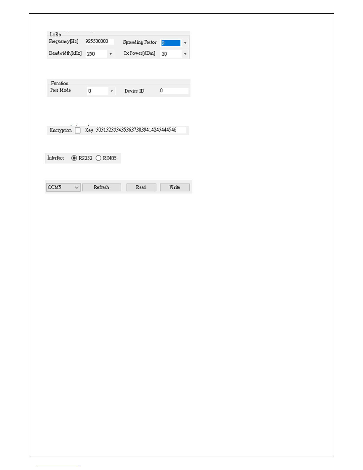
Lora
Frequency [Hz] 915500000 Spreading Factor 9 **
Bandwidth
[kHz]
125 Tx Power [
dBm
] 20
Encryption 30313233343536373839414243444546

15
4.2 Dip Switch
1) Setting mode: #1~#4 pins all at up position to modify LoRa settings.
2) Operation mode: only #1 at down position to run data transmission.
5. LoRa setting process
5.1 Pull power off
5.1.1 For Ethernet to LoRa model: pull off power plug.
5.1.2 For Serial to LoRa model: pull off power plug, use a USB to RS-232 Converter to onnect with the
RS-232 port. A crosslink RS-232 adaptor is necessary.
5.1.3 For USB to LoRa model: pull off USB plug from NB/PC USB host.
5.1.4 For DI/DO to LoRa model: pull off power plug.
5.2 Poke Dip Switch #1 to down position as setting mode.
5.3 Plug in the power plug or USB plug to turn power ON.
5.4 Recognize LoRa device’s COM port
5.5 Running the Setting Tool:
1) Press “Refresh” button, select right COM port number.
2) Press “Read” button to read existing parameters out.
3) Modify parameters as follows.
5.6 Setting UART parameters
16
5.7 Setting LoRa parameters
5.8 Function Pass Mode and Device ID: discard this function temporarily
5.9 Encryption value should be same on paring devices. Encryption is optional for
security purpose.
5.10 Interface: discard this function temporarily.
5.11 Press “Write” button to write parameters back to device.
5.12 Pull off power plug or USB plug to turn power off.
5.13 Poke Dip Switch #1 back to down position enable operation mode.
5.14 Plug into the power plug or USB plug to turn power on.

17
6. Ethernet to LoRa settings
6.1 Installation of IP Search Tool
6.1.1 Find out “CVBrowser.EXE” in the CD ROM, copy the file to your host computer.
6.1.2 Double click to run “CVBrowser.EXE”, a window will pop up as below.
6.2 Hardware Connection
6.2.1 Connect host computer and LR-201-E to Switch Hub with RJ45 Ethernet cable.
6.2.2 Power on LR-201-E.
6.2.3 Click the icon of Binocular as “Refresh”, it will search and show up the IP of
Converter (Default IP: 192.168.0.100).
6.2.6 IP of Converter changing subnet to match with host PC/NB. Clicking
“Serial_TCPIP” per below.
6.2.7 Click on the icon of “Modify IP”. Input IP and click “Confirm” twice. No need to
input password.

18
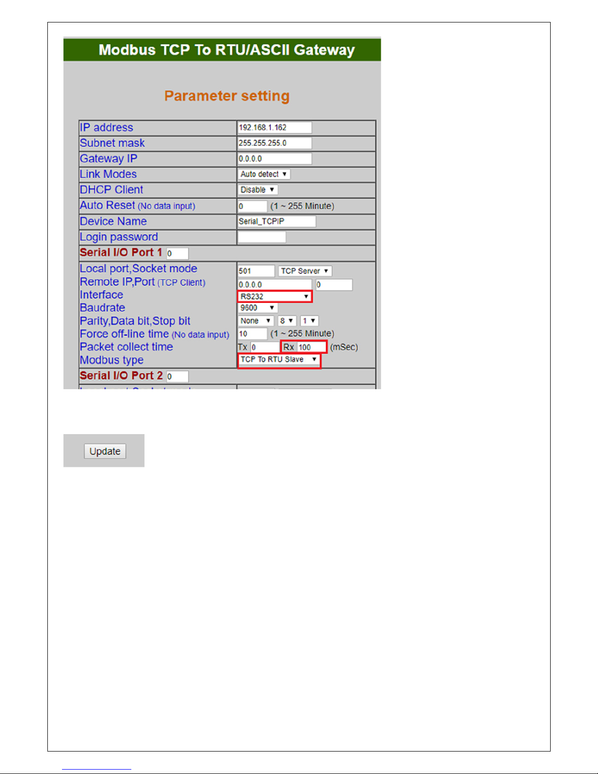
6.3 Input Converter’s IP to Web browser. Configuration pate will show up. Click “Login”
without password.
6.4 LoRa module only use port #1 with default socket 501. Please don’t change the
parameters inside the red square. Port #2 is not used.
19
6.5 Press “Update” to save new parameters and reboot.

20
7. Serial Interface to LoRa Settings
Just follow above LoRa setting procedure. This device without
WEB interface settings.
8. USB to LoRa Settings
Just follow above LoRa setting procedure. This device without
WEB interface settings.
9. LoRa to DI/DO: Modbus codes
9.1 Digital Output
9.1.1 port #1 ON : 01 06 00 00 00 01
9.1.2 port #1 OFF: 01 06 00 00 00 00
9.1.3 port #2 ON : 02 06 00 00 00 01
9.1.4 port #2 OFF: 02 06 00 00 00 00
9.2 Digital Input
9.2.1 port #1 : 01 03 00 00 00 01
9.2.2 port #2 : 02 03 00 00 00 01
21
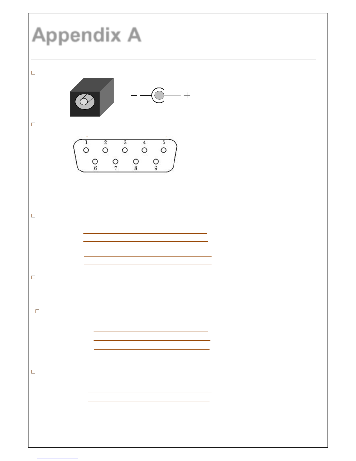
Appendix A
Pin Assignment
DC Power outlet
RS-232 Pin Assignment
The pin assignment scheme for a 9-pin male connector on a DTE is given below.
PIN 1 : DCD PIN 2 : RXD PIN 3 : TXD PIN 4 : DTR
PIN 5 : GND PIN 6 : DSR PIN 7 : RTS PIN 8 : CTS
PIN 9 : X
RS-232 Wiring Diagram
Serial Device Converter
2 RX 3 TX
3 TX 2 RX
5 GND 5 GND
7 RTS 8 CTS
8 CTS 7 RTS
RS-422/485 Pin Assignment
The pin assignment scheme for a 4-pin RS-422 and 2-pin RS-485 as given below.
RS-422 Wiring Diagram
Serial Device Converter
R- T R+ T+
T- R T+ R+
RS-485 Wiring Diagram
Serial Device Converter
D+ D+
D- D-
 Loading...